astro ® xts™ 1500 1 cover astro ® xts tm 1500 digital portable radio interactive end-user...
TRANSCRIPT

ASTRO® XTS™ 1500
1
Cover
ASTRO® XTSTM 1500Digital Portable Radio
Interactive End-User Training
Insert picture from Photo Library here.(Delete this text and
surrounding box.)
ST. CLAIR COUNTY

ASTRO® XTS™ 1500
2
Index
1 Cover
2 Index
3 XTS 1500
4 Your Radio
5 Getting Started
6 Fleet Map – Radio Templates
7 Status Alert Tones
8 Installation and Removal Procedures
9 Antenna
10 Battery – 1 of 2
11 Charging the Battery - 2 of 2
12 Universal Connector Cover
13 Belt Clip
14 GENERAL FEATURES
15 Radio On/Off/Volume
16 Call Alert Page – Respond
17 Transmit and Receive
18 LED Status
19 Time-out Timer
20 16-POSITION SELECT KNOB
21 Talkgroup/Channel Select (16-Position Select Knob)
22 TOP BUTTON
23 Emergency – Send (Top Button) – 1 of 3
24 Emergency – Send Emergency Call (Top Button) – 2 of 3
25 Emergency – Send Emergency Call (Top Button) – 3 of 3
26 TOP SIDE BUTTON
27 Auto Scan (Top Side Button)
28 SIDE BUTTON 1
29 Call Alert Respond (Side Button 1)
30 Private Call – Respond (Side Button 1)
31 Direct/TalkAround (Side Button 1)

ASTRO® XTS™ 1500
3
XTS 1500
Fleet Map
C2
C1
Z2Z1
Your Radio
Installation andRemoval
Status Alert Tones

ASTRO® XTS™ 1500
4
Your Radio
Control Top Side Buttons
Push-To-Talk
(PTT) Button
Auto Scan
Call Alert (Respond(-(Trunked)
Private Call (Respond)-(Trunked)
Direct/Talkaround –(Conventional)
Unprogrammed
Talkgroup/Channel Select
ABC Switch Not
Programmed
EmergencyPower On/Off
Volume Control

ASTRO® XTS™ 1500
5
Fleet Map – Radio Templates
See the Radio Template for your specific entity

ASTRO® XTS™ 1500
6
Status Alert Tones
Tone Name Tone Information
Acknowledge Receipt of a call sent to the central controller
Button Press A valid key was pressed on the keypad
Call Alert- Receipt of a Call Alert page sent to your radio- Confirmation receipt of a page received sent from your radio
Emergency Emergency alarm was sent from your radio
Failsoft Radio has lost communication with the central controller
Low Battery Weak battery indication
No Acknowledge A call to the central controller was not acknowledged
Out of Range Radio is out of range of the system
Power-up Radio has successfully powered on
Private Call I Receipt of a Private Conversation call sent to your radio
Private Call Enhanced Receipt of a Private Conversation call sent to your radio
Prohibit Talkgroup/Channel or talkgroup/channel is not accessible
System Busy Talkgroup/Channel, system or target radio is busy
Talk Permit Talkgroup/Channel is ready to use
Time-out Timer Time-out timer limit has been reached

ASTRO® XTS™ 1500
7
Installation andRemoval Procedures
BatteryAntenna
Belt ClipUniversal Connector

ASTRO® XTS™ 1500
8
To install the antenna:
1. Turn the radio off.
2. Screw the antenna (clockwise) into the antenna receptacle on top of the radio.
3. Tighten the antenna firmly with your fingers.
To remove the antenna:
1. Turn the radio off.
2. Unscrew the antenna (counter-clockwise) and remove it from the antenna receptacle on top of the radio.
Antenna

ASTRO® XTS™ 1500
9
Battery – 1 of 2
To install the battery:
1. Turn the radio off.
2. Align the three tabs at the bottom of the battery with the three slots at the bottom of the back of the radio.
3. Angle the battery forward toward the radio until the battery clicks into place.
To remove the battery:
1. Turn the radio off.
2. Holding the radio in one hand, push down on the battery release slides on both sides of the battery with the other hand.
3. Angle the battery away from the radio and remove.
Battery procedures continued on next panel.

ASTRO® XTS™ 1500
10
Charging the Battery - 2 of 2
The battery must be charged before use.
Memory effect is a phenomenon that causes a loss in battery capacity or voltage due to repetitive shallow discharging or long-term overcharging. This memory effect has been greatly reduced in your batteries through the use of new cell technology.
It is still recommended, however, that you discharge your battery as much as possible before recharging it.
Recharging after each shift is good standard practice.
When charging a battery that is attached to your radio, turn the radio off to ensure a full charge.

ASTRO® XTS™ 1500
11
The universal connector cover protects the sideconnector near the antenna.
To remove the cover:
1. Turn the radio off.
2. Carefully insert a flat-bladed screwdriver between the bottom of the cover and the connector.
3. Holding the top of the cover with your thumb, push the screwdriver gently downward and lever the cover away from the radio.
To install the cover:
1. Turn the radio off.
2. Insert the hooked end of the cover into the slot above the connector.
3. Rub the ball of your thumb from the top to the bottom of the cover, applying pressure towards the radio. This will flex the cover and snap it into place.
Universal Connector Cover

ASTRO® XTS™ 1500
12
Belt Clip
To install the belt clip:
1. Remove battery before installing or removing the belt clip.
2. Hold the battery with the back of the battery facing you.
3. Hold the belt clip with the top facing upward, and align the clip with the slots on the battery back.
4. Slide the belt clip downward into the slots until it clicks into place.
To remove the belt clip:
1. Pull away the metal tab at the top of the battery clip from the battery.
2. Slide the clip upward until it comes away from the radio.
1
2

ASTRO® XTS™ 1500
13
GENERAL FEATURESGENERAL FEATURES

ASTRO® XTS™ 1500
14
To turn the radio on:
Turn the On/Off/Volume Control knob clockwise.
If the power-up test is successful, a power-up toneis heard (if enabled).
If the power-up test is unsuccessful, you hear a low-pitched tone. Turn off the radio, check the battery and turn the radio on again. If the radio fails the power-up test again, contact a qualified radio technician.
To turn the radio off:
Turn the On/Off/Volume Control knob counter-clockwise until it clicks.
Radio On/Off/Volume
On/Off/VolumeKnob
ASTRO® XTS™ 1500
15
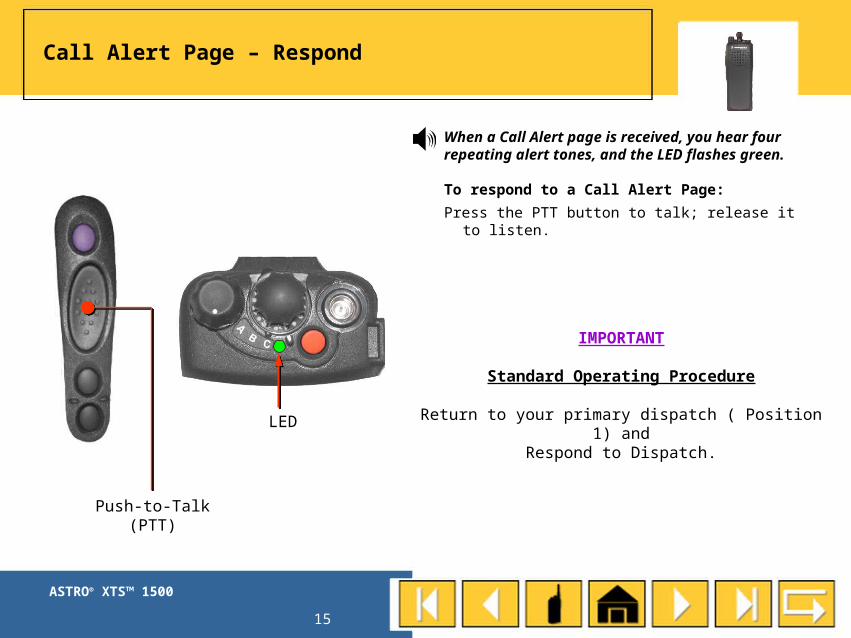
Call Alert Page – Respond
When a Call Alert page is received, you hear fourrepeating alert tones, and the LED flashes green.
To respond to a Call Alert Page:
Press the PTT button to talk; release it to listen.
LED
Push-to-Talk(PTT)
IMPORTANT
Standard Operating Procedure
Return to your primary dispatch ( Position 1) andRespond to Dispatch.
ASTRO® XTS™ 1500
16
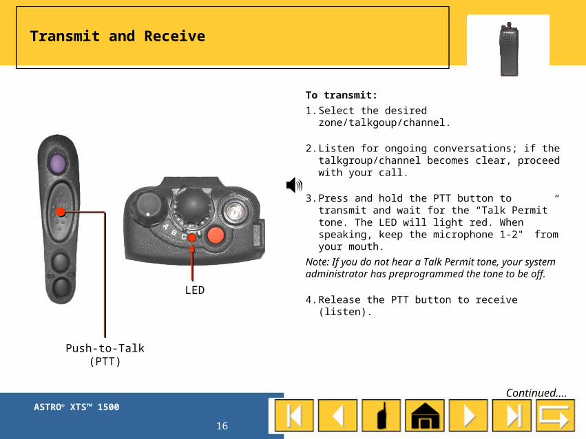
To transmit:
1. Select the desired zone/talkgoup/channel.
2. Listen for ongoing conversations; if the talkgroup/channel becomes clear, proceed with your call.
3. Press and hold the PTT button to transmit and wait for the “Talk Permit” tone. The LED will light red. When speaking, keep the microphone 1-2" from your mouth.
Note: If you do not hear a Talk Permit tone, your system administrator has preprogrammed the tone to be off.
4. Release the PTT button to receive (listen).
Transmit and Receive
LED
Push-to-Talk(PTT)
Continued....
ASTRO® XTS™ 1500
17
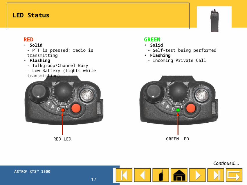
LED Status
RED LED GREEN LED
RED• Solid
- PTT is pressed; radio is transmitting• Flashing
- Talkgroup/Channel Busy- Low Battery (lights while transmitting)
GREEN• Solid
- Self-test being performed• Flashing
- Incoming Private Call
Continued....

ASTRO® XTS™ 1500
18
Time-out Timer
The time-out timer turns off your radio’s transmitter. The timer is set for 60 seconds.
1. Hold down the PTT button longer than the programmed time.
You will hear a low-pitched warning tone, the transmission will cut off, and the LED will go out until you release the PTT.
2. Release the PTT button.
The LED will re-light and the timer will reset.
3. Press the PTT button to re-transmit. The time-out timer restarts.
The timer will restart and the LED lights red.
LED
Push-to-Talk(PTT)

ASTRO® XTS™ 1500
19
16-POSITION SELECT 16-POSITION SELECT KNOBKNOB

ASTRO® XTS™ 1500
20
To select a talkgroup/channel:
Rotate the 16-Position Talkgroup/Channel Select knob to the desired position.
If the talkgroup/channel you selected is unprogrammed, youhear an alert tone. Repeat the above step.
Talkgroup/Channel Select(16-Position Select Knob)
Talkgroup/ChannelSelect Knob
NOTE: Position 16 is an Emergency Talkgroup that will always be monitored by dispatch
ASTRO® XTS™ 1500
21
TOP BUTTONTOP BUTTON

ASTRO® XTS™ 1500
22
To send an emergency signal from your radio:
Emergency – Send(Top Button) – 1 of 3
Send anemergency call.
EmergencyButton

ASTRO® XTS™ 1500
23
Emergency – SendEmergency Call(Top Button) – 2 of 3
Continued on next slide.
EmergencyButton
LED
To send an emergency call:Press the orange Emergency button. Your radio reverts to emergency status and has priority access to the EMRGNCY 1 talkgroup.
*an audible alert is heard and displayed at every dispatch console in CENCOM
The radio operates in the normal manner while in emergency call status, except you are no longer on your selected talkgroup.
You talk on the preprogrammed emergency talkgroup - EMRGNCY 1 - that is monitored by dispatch. The emergency alarm is sent on this same talkgroup.
. The LED lights red, and you hear a group of short,medium-pitched tones.
NOTE: If you are selected to a conventional channel, you may not be able to send an emergency call. When you press the orange button, your radio will emit a prohibit tone indicating that the emergency function is not available on the selected channel.
ASTRO® XTS™ 1500
24
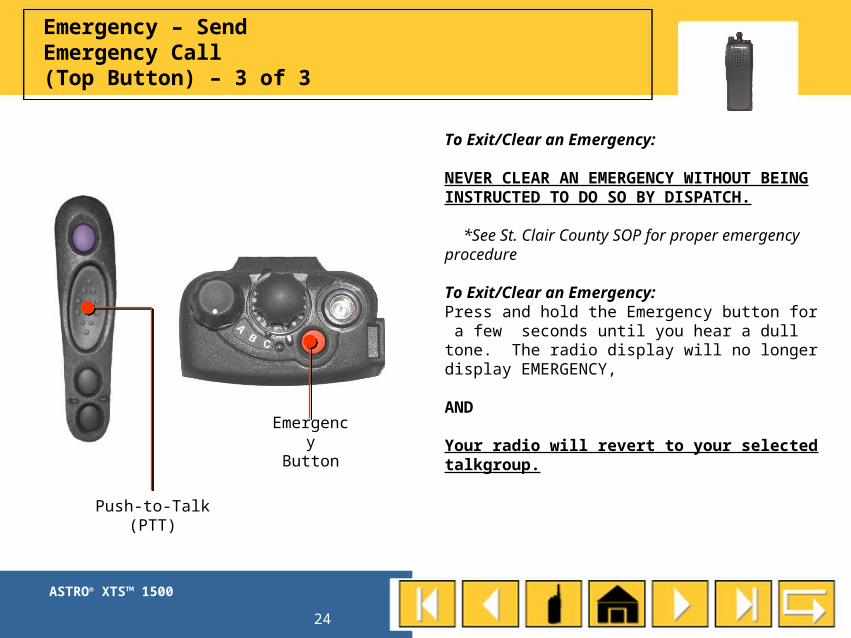
Emergency – SendEmergency Call(Top Button) – 3 of 3
Push-to-Talk(PTT)
EmergencyButton
To Exit/Clear an Emergency:
NEVER CLEAR AN EMERGENCY WITHOUT BEING INSTRUCTED TO DO SO BY DISPATCH.
*See St. Clair County SOP for proper emergency procedure
To Exit/Clear an Emergency:Press and hold the Emergency button for a few seconds until you hear a dull tone. The radio display will no longer display EMERGENCY,
AND
Your radio will revert to your selected talkgroup.

ASTRO® XTS™ 1500
25
TOP SIDE BUTTONTOP SIDE BUTTON

ASTRO® XTS™ 1500
26
Auto Scan (Top Side Button)
Auto Scan:
Your radio is programmed with auto scan.
The scan feature allows you to monitor traffic on different talkgroups/channels by scanning a preprogrammed list of talkgroups/channels.
Your radio will always scan:
Your primary dispatch talkgroup/channel (position 1)
However, if your selected talkgroup is not your primary dispatch talkgroup/channel and someone transmits on your selected talkgroup/channel, you will hear their transmission rather than your primary dispatch.
Unprogrammed
ASTRO® XTS™ 1500
27
SIDE BUTTON 1SIDE BUTTON 1
ASTRO® XTS™ 1500
28
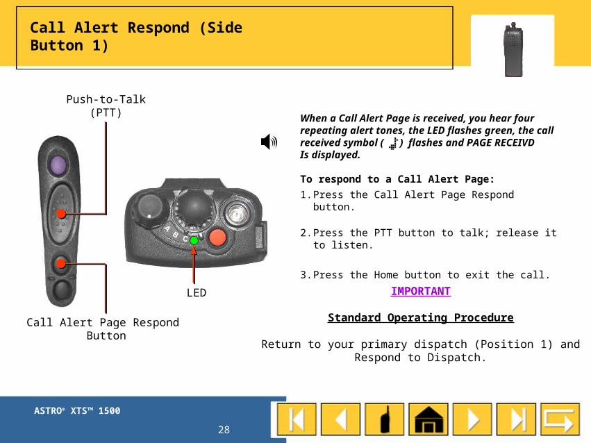
Call Alert Respond (Side Button 1)
LED
Push-to-Talk(PTT)
Call Alert Page Respond Button
When a Call Alert Page is received, you hear fourrepeating alert tones, the LED flashes green, the callreceived symbol ( ) flashes and PAGE RECEIVD Is displayed.
To respond to a Call Alert Page:
1. Press the Call Alert Page Respond button.
2. Press the PTT button to talk; release it to listen.
3. Press the Home button to exit the call.
IMPORTANT
Standard Operating Procedure
Return to your primary dispatch (Position 1) andRespond to Dispatch.

ASTRO® XTS™ 1500
29
Private Call – Respond (Side Button 1)
When a Private Call is received, you hear two alert tones and the LED flashes green.
To respond to a Private Call:
1. Press the Private Call Respond button within 20 seconds.
2. Press and hold the PTT button to talk; release it to listen.
3. Press the Private Call Respond button again to hang up.
LED
Push-to-Talk(PTT)
Private Call Respond Button

ASTRO® XTS™ 1500
30
Direct/TalkAround(Side Button 1)
DirectButton
Applies only to SC I-CALL and SC I-TAC 1-4.Also known as “talk-around operation,” direct lets you bypass the repeater and connect directly to another radio. The transmit and receive frequencies are the same.
To directly connect with another radio:
1. Select a conventional channel from the fleet map list provided by your system administrator.
2. Press the Direct button to enable this feature.
3. Press the Direct button again to disengage the feature and return to normal radio operation.
NOTE: Make sure the receiving unit has the same channel configuration selected. You will not receive normal trunked, talkgroup/channel calls while in direct mode.