astralpool australia led underwater niche · pdf fileinstallation and operating instructions...
TRANSCRIPT
Rev. H – 22/01/2010 A division of Fluidra
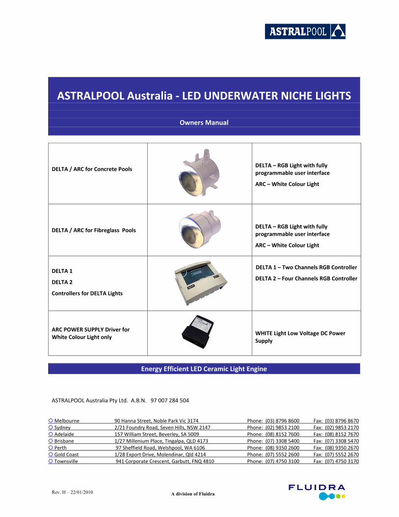
ASTRALPOOL Australia ‐ LED UNDERWATER NICHE LIGHTS
Owners Manual
DELTA / ARC for Concrete Pools
DELTA – RGB Light with fully programmable user interface
ARC – White Colour Light
DELTA / ARC for Fibreglass Pools
DELTA – RGB Light with fully programmable user interface
ARC – White Colour Light
DELTA 1
DELTA 2
Controllers for DELTA Lights
DELTA 1 – Two Channels RGB Controller
DELTA 2 – Four Channels RGB Controller
ARC POWER SUPPLY Driver for White Colour Light only
WHITE Light Low Voltage DC Power Supply
Energy Efficient LED Ceramic Light Engine
ASTRALPOOL Australia Pty Ltd. A.B.N. 97 007 284 504
Melbourne 90 Hanna Street, Noble Park Vic 3174 Phone: (03) 8796 8600 Fax: (03) 8796 8670 Sydney 2/21 Foundry Road, Seven Hills, NSW 2147 Phone: (02) 9853 2100 Fax: (02) 9853 2170 Adelaide 157 William Street, Beverley, SA 5009 Phone: (08) 8152 7600 Fax: (08) 8152 7670 Brisbane 1/27 Millenium Place, Tingalpa, QLD 4173 Phone: (07) 3308 5400 Fax: (07) 3308 5470 Perth 97 Sheffield Road, Welshpool, WA 6106 Phone: (08) 9350 2600 Fax: (08) 9350 2670 Gold Coast 1/28 Export Drive, Molendinar, Qld 4214 Phone: (07) 5552 2600 Fax: (07) 5552 2670 Townsville 941 Corporate Crescent, Garbutt, FNQ 4810 Phone: (07) 4750 3100 Fax: (07) 4750 3170

Installation and Operating Instructions Page 2 A division of Fluidra
INDEX
1.0 General Overview............................................................................................................................ 3
2.0 DELTA Light Connectivity Possibility ................................................................................................ 5
3.0 Niche Light Installation Dimensions................................................................................................. 6
4.0 Installation Instructions for Concrete Pools & Spas ......................................................................... 7
5.0 Installation Instructions for Fibreglass Pools & Spas...................................................................... 11
6.0 General Operation White Pool Light.............................................................................................. 13
7.0 RGB Pool Light Controller – User Panel ......................................................................................... 13
8.0 Cable Colour Code......................................................................................................................... 16
9.0 Connecting Extension Module....................................................................................................... 17
10.0 Maintenance ............................................................................................................................... 19
11.0 Warranty..................................................................................................................................... 19
Installation and Operating Instructions Page 3 A division of Fluidra
1.0 General Overview
Congratulations! You have purchased a Hurlcon APL energy efficient LED pool light. The RGB multi‐colour version has fully programmable user panel to offer: adjustment of the light saturation, speed, the colour selection, making own colours and light fade options. Please read the instructions carefully and your purchase will provide you with satisfaction and years of trouble free use.
Note: The appliance is not intended for use by young children or infirm person without supervision. Please ensure that young children are supervised to ensure that they do not play with the appliance.
The following ASTRALPOOL Niche Lights are available: For concrete pools and spas:
ARC White light with 20m cable P/N46500
DELTA RGB Multicolour light with 20m cable P/N46600
For fibreglass pools and spas:
ARC White light with 20m cable P/N46550
DELTA RGB Multicolour light with 20m cable P/N46650
ASTRALPOOL lights will work with the following drivers:
ARC Light Power Supply for one white light only (each light must have its own power supply) P/N20320
DELTA Light Controller Single ‐ for two RGB lights P/N20314
DELTA 2 Light Controller Dual‐ for four RGB lights P/N20315
DELTA PLUS Light Controller Single Expansion ‐ two extra RGB lights P/N20316
DELTA 2 PLUS Light Controller Dual Expansion ‐ four extra RGB lights P/N20317
SURTIDO Controller‐Light Single & Waterfall Single (two RGB lights & one 2400mm RGB waterfall) P/N20318
SURTIDO PLUS Controller‐Light Single Expansion & Waterfall Single Expansion (two RGB lights & one 2400mm max. RGB waterfall) P/N20319
NOTE: Delta 2 Plus Dual Expansion Controller can be connected to each other up to four units giving total output of 16 RGB
working lights. Technical Data
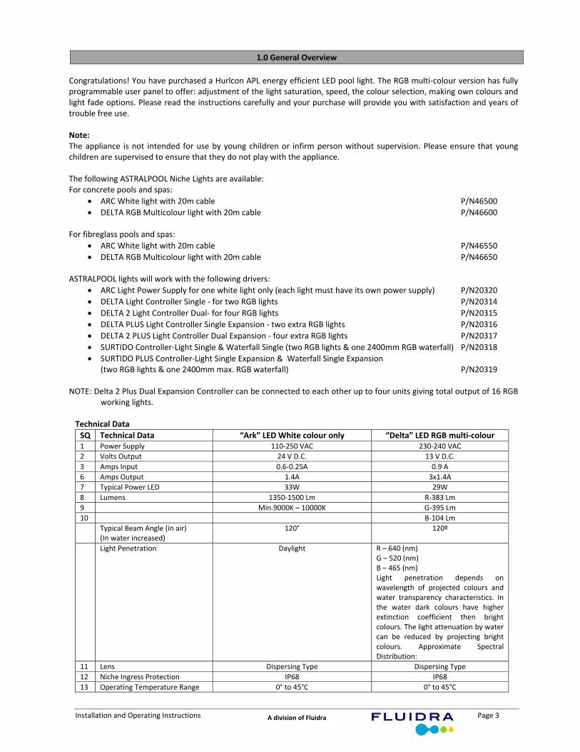
SQ Technical Data “Ark” LED White colour only “Delta” LED RGB multi‐colour 1 Power Supply 110‐250 VAC 230‐240 VAC
2 Volts Output 24 V D.C. 13 V D.C.
3 Amps Input 0.6‐0.25A 0.9 A
6 Amps Output 1.4A 3x1.4A
7 Typical Power LED 33W 29W
8 Lumens 1350‐1500 Lm R‐383 Lm
9 Min.9000K – 10000K G‐395 Lm
10 B‐104 Lm
Typical Beam Angle (in air) (In water increased)
120° 120º
Light Penetration Daylight R – 640 (nm) G – 520 (nm) B – 465 (nm) Light penetration depends on wavelength of projected colours and water transparency characteristics. In the water dark colours have higher extinction coefficient then bright colours. The light attenuation by water can be reduced by projecting bright colours. Approximate Spectral Distribution:
11 Lens Dispersing Type Dispersing Type
12 Niche Ingress Protection IP68 IP68
13 Operating Temperature Range 0° to 45°C 0° to 45°C
Installation and Operating Instructions Page 4 A division of Fluidra
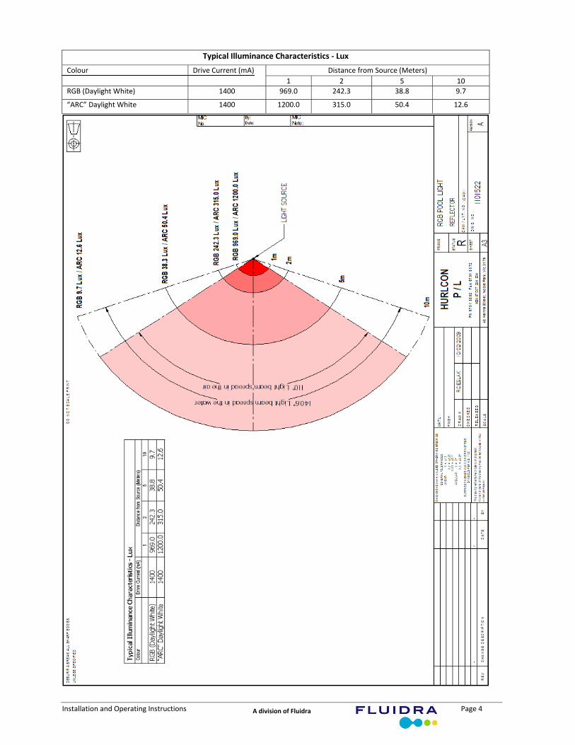
Typical Illuminance Characteristics ‐ Lux
Distance from Source (Meters) Colour Drive Current (mA)
1 2 5 10
RGB (Daylight White) 1400 969.0 242.3 38.8 9.7
“ARC” Daylight White 1400 1200.0 315.0 50.4 12.6
Installation and Operating Instructions Page 5 A division of Fluidra
2.0 DELTA Lights Connectivity Possibility
WARNING: Qualified person in accordance with AS/NZ 3000:2000 standards must install the Lighting system. Improper installation could result in property damage. Improper installation will void the warranty.
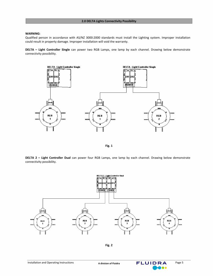
DELTA – Light Controller Single can power two RGB Lamps, one lamp by each channel. Drawing below demonstrate connectivity possibility.
Fig. 1
DELTA 2 – Light Controller Dual can power four RGB Lamps, one lamp by each channel. Drawing below demonstrate connectivity possibility.
Fig. 2

Installation and Operating Instructions Page 6 A division of Fluidra
3.0 Niche Light Installation Dimensions
Dimensions in mm:
Light for Concrete Pool & Spa Fig. 3
Light for Fibreglass Pool & Spa Fig. 4
Installation and Operating Instructions Page 7 A division of Fluidra
4.0 Installation Instruction for concrete pools and spas
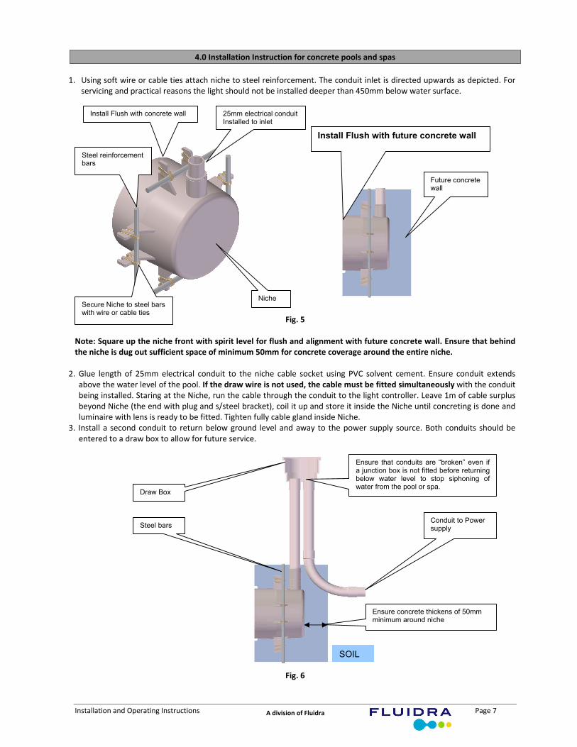
1. Using soft wire or cable ties attach niche to steel reinforcement. The conduit inlet is directed upwards as depicted. For
servicing and practical reasons the light should not be installed deeper than 450mm below water surface.
Fig. 5 Note: Square up the niche front with spirit level for flush and alignment with future concrete wall. Ensure that behind the niche is dug out sufficient space of minimum 50mm for concrete coverage around the entire niche.
2. Glue length of 25mm electrical conduit to the niche cable socket using PVC solvent cement. Ensure conduit extends above the water level of the pool. If the draw wire is not used, the cable must be fitted simultaneously with the conduit being installed. Staring at the Niche, run the cable through the conduit to the light controller. Leave 1m of cable surplus beyond Niche (the end with plug and s/steel bracket), coil it up and store it inside the Niche until concreting is done and luminaire with lens is ready to be fitted. Tighten fully cable gland inside Niche.
3. Install a second conduit to return below ground level and away to the power supply source. Both conduits should be entered to a draw box to allow for future service.
Fig. 6
25mm electrical conduit Installed to inlet
Niche Secure Niche to steel bars with wire or cable ties
Steel reinforcement bars
Steel bars
Draw Box
Conduit to Power supply
Ensure concrete thickens of 50mm minimum around niche
SOIL
Install Flush with concrete wall
Install Flush with future concrete wall
Future concrete wall
Ensure that conduits are “broken” even if a junction box is not fitted before returning below water level to stop siphoning of water from the pool or spa.
Installation and Operating Instructions Page 8 A division of Fluidra
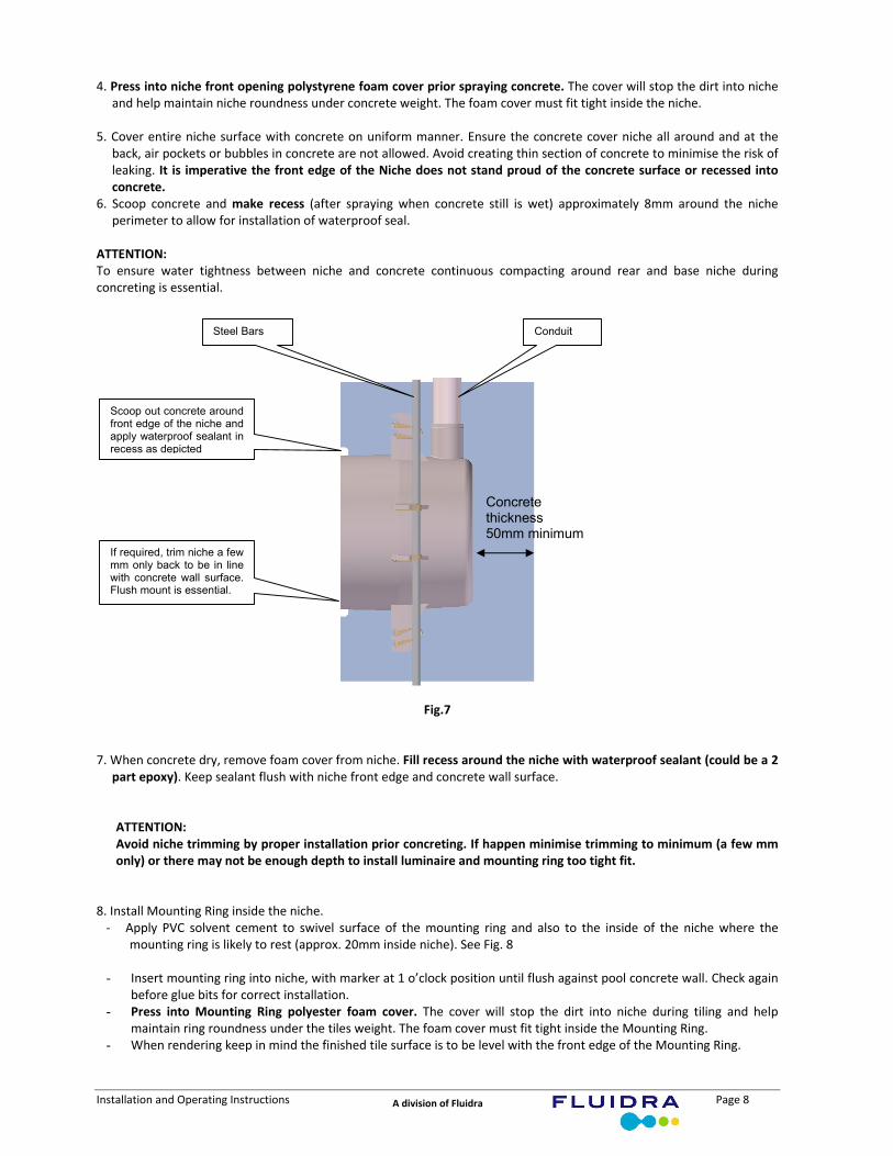
4. Press into niche front opening polystyrene foam cover prior spraying concrete. The cover will stop the dirt into niche and help maintain niche roundness under concrete weight. The foam cover must fit tight inside the niche.
5. Cover entire niche surface with concrete on uniform manner. Ensure the concrete cover niche all around and at the
back, air pockets or bubbles in concrete are not allowed. Avoid creating thin section of concrete to minimise the risk of leaking. It is imperative the front edge of the Niche does not stand proud of the concrete surface or recessed into concrete.
6. Scoop concrete and make recess (after spraying when concrete still is wet) approximately 8mm around the niche perimeter to allow for installation of waterproof seal.
ATTENTION: To ensure water tightness between niche and concrete continuous compacting around rear and base niche during concreting is essential.
Fig.7
7. When concrete dry, remove foam cover from niche. Fill recess around the niche with waterproof sealant (could be a 2
part epoxy). Keep sealant flush with niche front edge and concrete wall surface.
ATTENTION: Avoid niche trimming by proper installation prior concreting. If happen minimise trimming to minimum (a few mm only) or there may not be enough depth to install luminaire and mounting ring too tight fit.
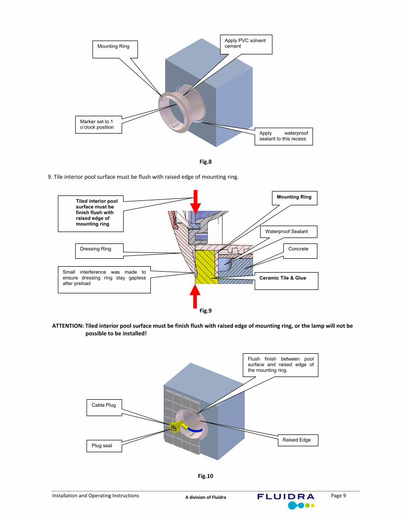
8. Install Mounting Ring inside the niche. ‐ Apply PVC solvent cement to swivel surface of the mounting ring and also to the inside of the niche where the
mounting ring is likely to rest (approx. 20mm inside niche). See Fig. 8
- Insert mounting ring into niche, with marker at 1 o’clock position until flush against pool concrete wall. Check again before glue bits for correct installation.
- Press into Mounting Ring polyester foam cover. The cover will stop the dirt into niche during tiling and help maintain ring roundness under the tiles weight. The foam cover must fit tight inside the Mounting Ring.
- When rendering keep in mind the finished tile surface is to be level with the front edge of the Mounting Ring.
Conduit Steel Bars
Scoop out concrete around front edge of the niche and apply waterproof sealant in recess as depicted
If required, trim niche a few mm only back to be in line with concrete wall surface. Flush mount is essential.
Concrete thickness 50mm minimum
Installation and Operating Instructions Page 9 A division of Fluidra
Fig.8
9. Tile interior pool surface must be flush with raised edge of mounting ring.
Fig.9 ATTENTION: Tiled interior pool surface must be finish flush with raised edge of mounting ring, or the lamp will not be
possible to be installed!
Fig.10
Marker set to 1 o’clock position
Apply waterproof sealant to this recess
Apply PVC solvent cement Mounting Ring
Raised Edge
Cable Plug
Flush finish between pool surface and raised edge of the mounting ring.
Plug seal
Mounting Ring
Ceramic Tile & Glue
Dressing Ring
Waterproof Sealant
Concrete
Tiled interior pool surface must be finish flush with raised edge of mounting ring
Small interference was made to ensure dressing ring stay gapless after preload
Installation and Operating Instructions Page 10 A division of Fluidra
NOTE: If the supply cord is damaged, it must be replaced by the manufacturer or its service agent or a similarly qualified person in order to avoid a hazard.
ATTENTION: Do not install the lamp until pool has been washed with acid.
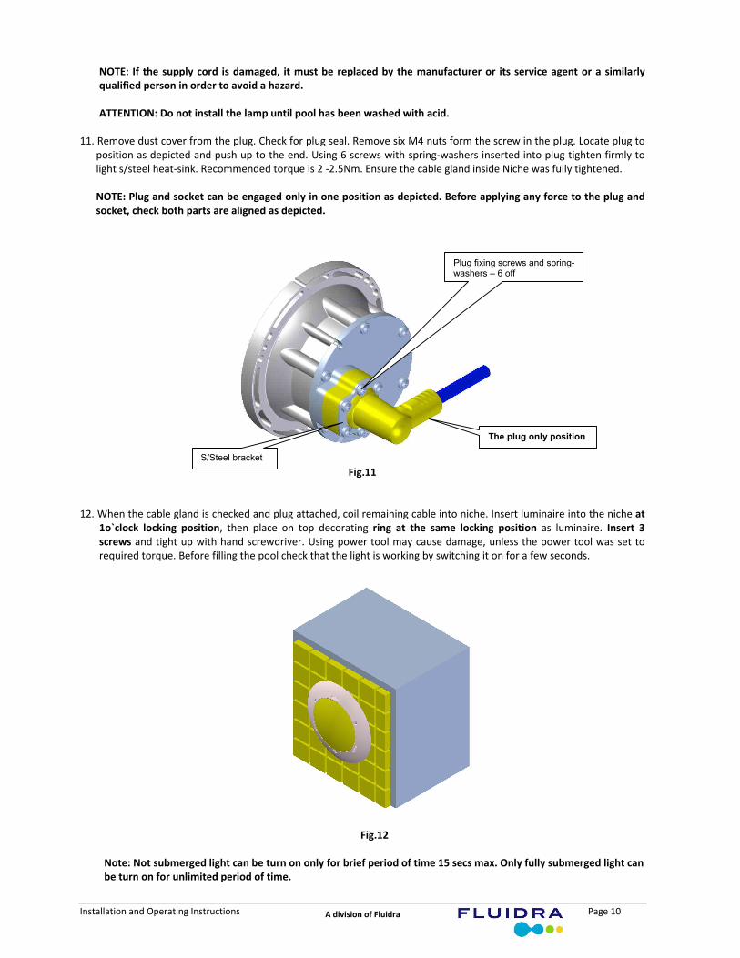
11. Remove dust cover from the plug. Check for plug seal. Remove six M4 nuts form the screw in the plug. Locate plug to
position as depicted and push up to the end. Using 6 screws with spring‐washers inserted into plug tighten firmly to light s/steel heat‐sink. Recommended torque is 2 ‐2.5Nm. Ensure the cable gland inside Niche was fully tightened.
NOTE: Plug and socket can be engaged only in one position as depicted. Before applying any force to the plug and socket, check both parts are aligned as depicted.
Fig.11
12. When the cable gland is checked and plug attached, coil remaining cable into niche. Insert luminaire into the niche at
1o`clock locking position, then place on top decorating ring at the same locking position as luminaire. Insert 3 screws and tight up with hand screwdriver. Using power tool may cause damage, unless the power tool was set to required torque. Before filling the pool check that the light is working by switching it on for a few seconds.
Fig.12
Note: Not submerged light can be turn on only for brief period of time 15 secs max. Only fully submerged light can be turn on for unlimited period of time.
Plug fixing screws and spring-washers – 6 off
The plug only position
S/Steel bracket
Installation and Operating Instructions Page 11 A division of Fluidra
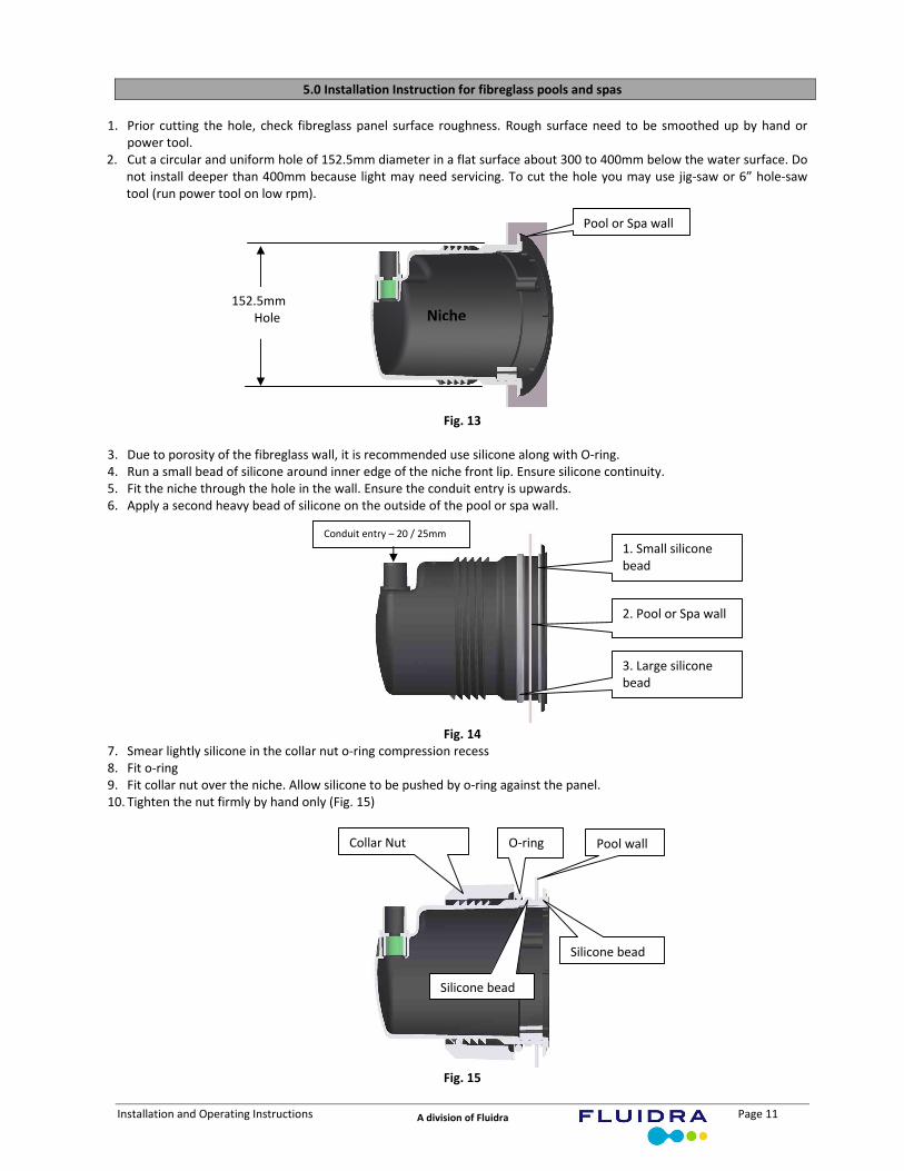
5.0 Installation Instruction for fibreglass pools and spas
1. Prior cutting the hole, check fibreglass panel surface roughness. Rough surface need to be smoothed up by hand or
power tool. 2. Cut a circular and uniform hole of 152.5mm diameter in a flat surface about 300 to 400mm below the water surface. Do
not install deeper than 400mm because light may need servicing. To cut the hole you may use jig‐saw or 6” hole‐saw tool (run power tool on low rpm).
Fig. 13
3. Due to porosity of the fibreglass wall, it is recommended use silicone along with O‐ring. 4. Run a small bead of silicone around inner edge of the niche front lip. Ensure silicone continuity. 5. Fit the niche through the hole in the wall. Ensure the conduit entry is upwards. 6. Apply a second heavy bead of silicone on the outside of the pool or spa wall.
Fig. 14
7. Smear lightly silicone in the collar nut o‐ring compression recess 8. Fit o‐ring 9. Fit collar nut over the niche. Allow silicone to be pushed by o‐ring against the panel. 10. Tighten the nut firmly by hand only (Fig. 15)
Fig. 15
Pool or Spa wall
Niche152.5mm
Hole
1. Small silicone bead
3. Large silicone bead
2. Pool or Spa wall
Conduit entry – 20 / 25mm
Collar Nut Pool wall O‐ring
Silicone bead
Silicone bead
Installation and Operating Instructions Page 12 A division of Fluidra
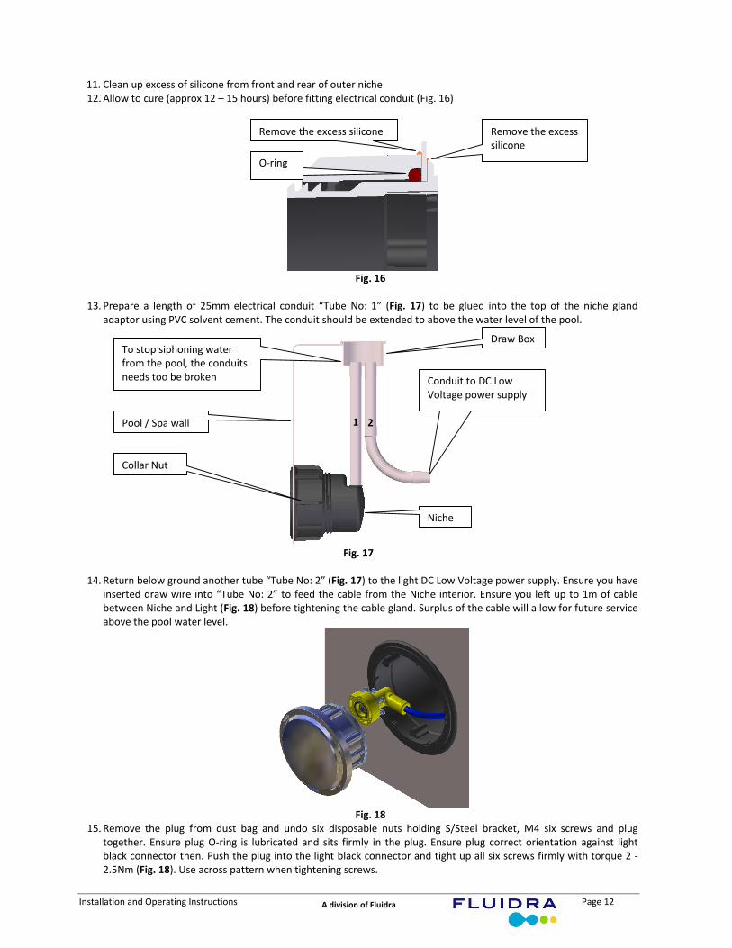
11. Clean up excess of silicone from front and rear of outer niche 12. Allow to cure (approx 12 – 15 hours) before fitting electrical conduit (Fig. 16)
Fig. 16
13. Prepare a length of 25mm electrical conduit “Tube No: 1” (Fig. 17) to be glued into the top of the niche gland
adaptor using PVC solvent cement. The conduit should be extended to above the water level of the pool.
Fig. 17
14. Return below ground another tube “Tube No: 2” (Fig. 17) to the light DC Low Voltage power supply. Ensure you have
inserted draw wire into “Tube No: 2” to feed the cable from the Niche interior. Ensure you left up to 1m of cable between Niche and Light (Fig. 18) before tightening the cable gland. Surplus of the cable will allow for future service above the pool water level.
Fig. 18
15. Remove the plug from dust bag and undo six disposable nuts holding S/Steel bracket, M4 six screws and plug together. Ensure plug O‐ring is lubricated and sits firmly in the plug. Ensure plug correct orientation against light black connector then. Push the plug into the light black connector and tight up all six screws firmly with torque 2 ‐2.5Nm (Fig. 18). Use across pattern when tightening screws.
O‐ring
Remove the excess silicone Remove the excess silicone
Pool / Spa wall
Draw Box
Conduit to DC Low Voltage power supply
Niche
Collar Nut
To stop siphoning water from the pool, the conduits needs too be broken
1 2

Installation and Operating Instructions Page 13 A division of Fluidra
16. Turning the light coil remaining cable and put it inside the niche. Lock the lamp in position on the tab (1pm o’clock) and push into the niche (Fig. 19).
Fig. 19
17. Have ready dressing ring and three s/steel screws to finish up the work. Dressing ring also clip at (1pm o’clock) position. Do not over tight the screws do up with manual screwdriver (Fig. 20).
Fig. 20
18. The end of installation procedure
6.0 General Operation White Pool Light
Ensure light power pack is connected to the GPO or power source. Ensure light cable is connected to the power pack. Turn on the power source. Your light should now start automatically (“Ark” Model only). To switch OFF, turn off GPO or power source. To switch ON or OFF the “Delta” Model, press ON/OFF soft‐key on the user panel.
7.0 RGB POOL LIGHT CONTROLLER – User Panel
The Controller operation can be divided into following functions: 1) Colours selection – selected colours can be switched ON or OFF permanently 2) Tuning the colours – each colour can be tuned up to discretion of the user (it is like adding extra pigment to the paint
to make it more greener) 3) Mode selection:
Locking tab position
Fibreglass Panel
Installation and Operating Instructions Page 14 A division of Fluidra
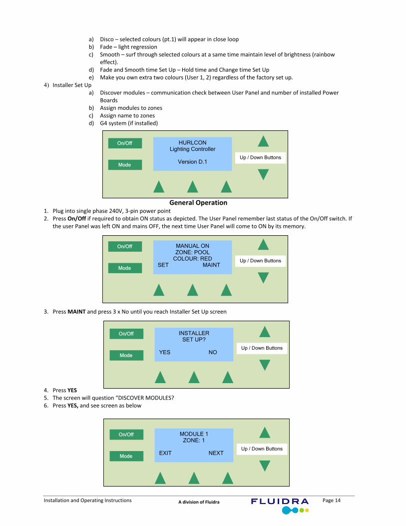
a) Disco – selected colours (pt.1) will appear in close loop b) Fade – light regression c) Smooth – surf through selected colours at a same time maintain level of brightness (rainbow
effect). d) Fade and Smooth time Set Up – Hold time and Change time Set Up e) Make you own extra two colours (User 1, 2) regardless of the factory set up.
4) Installer Set Up a) Discover modules – communication check between User Panel and number of installed Power
Boards b) Assign modules to zones c) Assign name to zones d) G4 system (if installed)
General Operation 1. Plug into single phase 240V, 3‐pin power point 2. Press On/Off if required to obtain ON status as depicted. The User Panel remember last status of the On/Off switch. If
the user Panel was left ON and mains OFF, the next time User Panel will come to ON by its memory.
3. Press MAINT and press 3 x No until you reach Installer Set Up screen
4. Press YES 5. The screen will question “DISCOVER MODULES? 6. Press YES, and see screen as below
HURLCONLighting Controller
Version D.1
On/Off
Mode
Up / Down Buttons
MANUAL ONZONE: POOL
COLOUR: RED SET MAINT
On/Off
Mode
Up / Down Buttons
INSTALLERSET UP?
YES NO
On/Off
Mode
Up / Down Buttons
MODULE 1ZONE: 1
EXIT NEXT
On/Off
Mode
Up / Down Buttons
Installation and Operating Instructions Page 15 A division of Fluidra
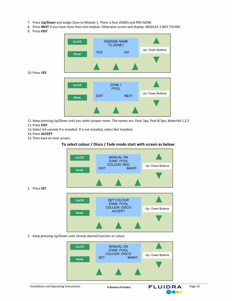
7. Press Up/Down and assign Zone to Module 1. There is four ZONES and fifth NONE. 8. Press NEXT if you have more than one module. Otherwise screen will display: MODULE 2 NOT FOUND. 9. Press EXIT
10. Press YES
11. Keep pressing Up/Down until you select proper name. The names are: Pool, Spa, Pool & Spa, Waterfall 1,2,3 12. Press EXIT 13. Select G4 console if is installed. If is not installed, select Not Installed. 14. Press ACCEPT 15. Then back to main screen.
To select colour / Disco / Fade mode start with screen as below:
1. Press SET
2. Keep pressing Up/Down until choose desired function or colour.
ASSIGNE NAMETO ZONE?
YES NO
On/Off
Mode
Up / Down Buttons
ZONE 1POOL
EXIT NEXT
On/Off
Mode
Up / Down Buttons
MANUAL ONZONE: POOL
COLOUR: RED EXIT MAINT
On/Off
Mode
Up / Down Buttons
SET COLOURZONE: POOL
COLOUR: DISCO ACCEPT
On/Off
Mode
Up / Down Buttons
MANUAL ONZONE: POOL
COLOUR: DISCO SET MAINT
On/Off
Mode
Up / Down Buttons
Installation and Operating Instructions Page 16 A division of Fluidra
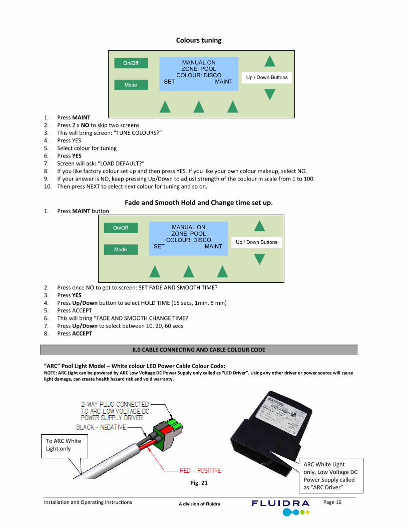
Colours tuning 1. Press MAINT 2. Press 2 x NO to skip two screens 3. This will bring screen: “TUNE COLOURS?” 4. Press YES 5. Select colour for tuning 6. Press YES 7. Screen will ask: “LOAD DEFAULT?” 8. If you like factory colour set up and then press YES. If you like your own colour makeup, select NO. 9. If your answer is NO, keep pressing Up/Down to adjust strength of the coulour in scale from 1 to 100. 10. Then press NEXT to select next colour for tuning and so on.
Fade and Smooth Hold and Change time set up. 1. Press MAINT button 2. Press once NO to get to screen: SET FADE AND SMOOTH TIME? 3. Press YES 4. Press Up/Down button to select HOLD TIME (15 secs, 1min, 5 min) 5. Press ACCEPT 6. This will bring “FADE AND SMOOTH CHANGE TIME? 7. Press Up/Down to select between 10, 20, 60 secs 8. Press ACCEPT
8.0 CABLE CONNECTING AND CABLE COLOUR CODE
“ARC” Pool Light Model – White colour LED Power Cable Colour Code: NOTE: ARC Light can be powered by ARC Low Voltage DC Power Supply only called as “LED Driver”. Using any other driver or power source will cause light damage, can create health hazard risk and void warranty.
Fig. 21
MANUAL ONZONE: POOL
COLOUR: DISCO SET MAINT
On/Off
Mode
Up / Down Buttons
MANUAL ONZONE: POOL
COLOUR: DISCO SET MAINT
On/Off
Mode
Up / Down Buttons
To ARC White Light only
ARC White Light only, Low Voltage DC Power Supply called as “ARC Driver”
Installation and Operating Instructions Page 17 A division of Fluidra
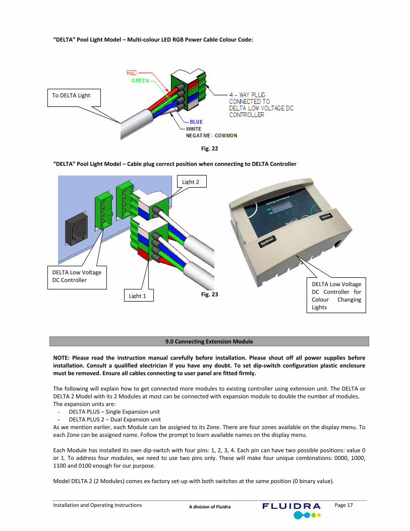
“DELTA” Pool Light Model – Multi‐colour LED RGB Power Cable Colour Code:
Fig. 22
“DELTA” Pool Light Model – Cable plug correct position when connecting to DELTA Controller
Fig. 23
9.0 Connecting Extension Module
NOTE: Please read the instruction manual carefully before installation. Please shout off all power supplies before installation. Consult a qualified electrician if you have any doubt. To set dip‐switch configuration plastic enclosure must be removed. Ensure all cables connecting to user panel are fitted firmly. The following will explain how to get connected more modules to existing controller using extension unit. The DELTA or DELTA 2 Model with its 2 Modules at most can be connected with expansion module to double the number of modules. The expansion units are:
- DELTA PLUS – Single Expansion unit - DELTA PLUS 2 – Dual Expansion unit
As we mention earlier, each Module can be assigned to its Zone. There are four zones available on the display menu. To each Zone can be assigned name. Follow the prompt to learn available names on the display menu. Each Module has installed its own dip‐switch with four pins: 1, 2, 3, 4. Each pin can have two possible positions: value 0 or 1. To address four modules, we need to use two pins only. These will make four unique combinations: 0000, 1000, 1100 and 0100 enough for our purpose. Model DELTA 2 (2 Modules) comes ex‐factory set‐up with both switches at the same position (0 binary value).
To DELTA Light
DELTA Low Voltage DC Controller
DELTA Low Voltage DC Controller for Colour Changing Lights
Light 1
Light 2

Installation and Operating Instructions Page 18 A division of Fluidra
Fig. 23
Fig.24 Power supply board
This means both Module will be addressed to one Zone only and both respond to mode or colours at a same time simultaneously. When running through “Installer Set Up” procedure, software will discover only one module installed in two modules model. Switching the pin no.1 from 0 to 1 binary value (on the Module 2), we disconnecting modules from work in tandem into two separately addressed modules:
Fig. 25
“Installer Set Up” procedure will discover two Modules as installed. Two Zones will be available for independent addressing and custom set‐up. For individual addressing next two modules in the extension unit positions of the dip‐switch should be as below:
Fig. 26
Having done above we will have four independently addressed modules for custom set‐up.
Installation and Operating Instructions Page 19 A division of Fluidra
10.0 Maintenance
If the supply cord is damaged, it must be replaced by AstralPool or its service agent or a similarly qualified person in order to avoid a hazard. NOTE: It is recommended practice that once a year all lamp sealing screws are check and tighten up if required.
11.0 WARRANTY
Your APL light is covered by a limited 1 year warranty. The Power Pack is covered by a 12 month warranty against defects in materials and assembly. To claim warranty, the Power Pack and/or light must be returned freight pre paid to your local AstralPool branch and include the date of purchase, from whom purchased and your full name, address and contact number. There are no user serviceable parts. Always turn off and disconnect power supply when removing Light. No representations may be made on AstralPool’s behalf by any person unless permission, in writing is obtained from AstralPool.
Limitations
All warranties only apply if the equipment is installed and operated in complete compliance with the installation and operating instructions. Specific limitations and exclusions include but are not limited to, water ingress into Power Pack or light assembly and damage caused through excessively rough handling. AstralPool assumes no liability for consequential damages of any kind. Should you request a warranty service call and the problem is diagnosed as non‐warrantable, you will be charged for a diagnostic service plus any parts and labour required to repair the light. No person is authorised to make any representations on behalf of AstralPool.
AstralPool Australia Pty Ltd. A.B.N. 97 007 284 504 Website: www.astralpool.com.au Email: [email protected]
Melbourne 90 Hanna Street, Noble Park Vic 3174 Phone: (03) 8796 8600 Fax: (03) 8796 8670 Sydney 2/21 Foundry Road, Seven Hills, NSW 2147 Phone: (02) 9853 2100 Fax: (02) 9853 2170 Adelaide 157 William Street, Beverley, SA 5009 Phone: (08) 8152 7600 Fax: (08) 8152 7670 Brisbane 1/27 Millenium Place, Tingalpa, QLD 4173 Phone: (07) 3308 5400 Fax: (07) 3308 5470 Perth 97 Sheffield Road, Welshpool, WA 6106 Phone: (08) 9350 2600 Fax: (08) 9350 2670 Gold Coast 1/28 Export Drive, Molendinar, Qld 4214 Phone: (07) 5552 2600 Fax: (07) 5552 2670 Townsville 941 Corporate Crescent, Garbutt, FNQ 4810 Phone: (07) 4750 3100 Fax: (07) 4750 3170