astral heat pumps bolero nd cleaner · inst253 astral heat pumps v09.11 4 introduction...
TRANSCRIPT

3/11/2016
INSTALLATION AND
OPERATING INSTRUCTIONS
Melbourne: 03 8796 8600 Gold Coast: 07 5552 2600 Perth: 08 9350 2600 Sydney: 02 9853 2100 Townsville: 07 4750 3100 [email protected] Brisbane: 07 3308 5400 Adelaide: 08 8152 7600 www.astralpool.com.au
Bolero ND Cleaner
INSTALLATION AND OPERATING INSTRUCTIONS I INSTALLATION AND OPERATING INSTRUCTIONS
Astral Heat Pumps

Inst253 Astral Heat Pumps V09.11 2

Inst253 Astral Heat Pumps V09.11 3
CONTENTS
Introduction
Introduction .............................................................................................. 3
Notice to Installers ................................................................................... 4
Safety Rules ............................................................................................. 4
Operation
Operating Instructions .............................................................................. 4
Chemical Balance .................................................................................... 5
Technical Specifications .......................................................................... 6
Digital Thermostat Operation .................................................................. 7
Fault Indication ........................................................................................ 8
Maintenance
Maintenance Instructions ......................................................................... 8
Energy saving Tips................................................................................... 8
Winter Operation...................................................................................... 9
Installation
Flow Rates.............................................................................................. 10
Water Connections ................................................................................. 10
Clearances .............................................................................................. 11
Electrical Connection ............................................................................. 11
Guide to Heat Pump Noise .................................................................... 12
Troubleshooting Fault Finding and Remedies .................................................................. 16
Wiring Diagrams .................................................................................... 17
Warranty
Terms and Conditions ............................................................................ 20

Inst253 Astral Heat Pumps V09.11 4
INTRODUCTION
Congratulations on the purchase of an Astral Pool Heat Pump, Pool and Spa Heater. Proper installation
and service of your new heating system and correct chemical maintenance of the water will ensure many
years of service. It is equipped with features that take advantage of new technology developed
exclusively by Astral Pool.
This unit can safely be connected to PVC pipe. In addition, the unit is equipped with an accurate
electronic thermostat to ensure ease of use and accurate temperature control. The electronic display tells
at a glance the operational status of the heater.
Your heat pump works by extracting heat from the surrounding air. The heat pump works most
efficiently in warm weather. So, it is best to operate the heat pump during the warmest part of the day
rather than overnight or early in the morning.
It is important to ensure an adequate supply of air and to avoid recirculation of the cooled air exiting the
top of the unit. For this reason, the heat pump should not be installed in confined spaces and must have a
minimum of 1500 mm clearance above it and 500 mm clearance to the sides and rear. A clearance of
1000mm is required to the front of the unit to allow access to the controls and service panel.
Although the unit is weatherproof, it is recommended some protection from the harsh effects of direct
exposure to the elements be provided.
The heat pump must be installed outdoors on a level concrete pad.
In most circumstances where heating is required, the heat pump will need to run longer than the filtration.
For the most effective heating it may be necessary to install a small pump to circulate water through the
heat pump independent of the filtration system. Since the heat pump uses electricity so efficiently, it is a
pity to waste electricity running an oversized pump. For this reason, the small added cost of a dedicated
pump can be recouped and a great deal of energy saved over the life of the heater.

Inst253 Astral Heat Pumps V09.11 5
NOTICE TO INSTALLERS
Heat Pump must be located outdoors with sufficient ventilation as explained on page 10.
This appliance must be installed by an authorized person.
This appliance must be installed in accordance with the installation instructions, the National Wiring
Rules and any other relevant statutory authorities.
Refer to data plate for details of operating voltage and current.
A multi-pole isolating switch must be installed that operates in all live conductors so that it isolates the
entire equipment from the supply.
Phase rotation must be checked on 3 phase units. Incorrect rotation will damage the compressor and void
any warranties.
SAFETY RULES
1. Spa or hot tub water temperature should never exceed 40˚C.
2. Drinking of alcoholic beverages before or during spa or hot tub use can cause drowsiness which could
lead to unconsciousness and subsequently result in drowning.
3. Pregnant women beware! Soaking in water above 38˚C can cause foetal damage during the first three
months of pregnancy.
4. Before entering the spa or hot tub, the user should check the water temperature with an accurate
thermometer, spa or hot tub thermostats may be inaccurate by as much as 2˚C.
5. Persons with a medical history of heart disease, circulatory problems, diabetes or blood pressure
problems should obtain their physician’s advice before using spas or hot tubs.
6. Persons taking medications which induce drowsiness, such as tranquillisers, antihistamines or
anticoagulants, should not use spas or hot tubs. If in doubt seek medical advice.
WARNING: Should overheating occur or the heater fail to shut off, turn off the manual isolation switch
to the appliance. Do not use this heater if any part has been under water.
OPERATING INSTRUCTIONS
1. STOP! Read the safety information above.
2. Turn filtration pump or dedicated pump on. The display should indicate flow.
3. Turn on power to the Heat Pump.
4. Set thermostat to desired setting
5. If the water temperature is below the set temperature, the fan will start. The compressor will start
in a few minutes. (Set by the compressor delay timer)
6. If the appliance will not operate, follow instructions 2 to 4 above ensuring the thermostat is set to
a higher temperature than the indicated water temperature. If the appliance still does not operate,
call your service technician.

Inst253 Astral Heat Pumps V09.11 6
During operation in weather below about 10 deg, ice may appear on the evaporator coil. An automatic
defrost mode will initiate. During a defrost cycle the compressor will continue to run however the
direction of the gas in the system is reversed so that the evaporator coil is heated. A ‘whoosh’ may be
heard as this occurs. The fan will continue to run in order to melt the accumulated ice. When the
evaporator temperature rises sufficiently to allow continued operation, the compressor will restart in
heating mode.
During this heated defrost mode, there may be visible water vapour in the airstream. This is normal
during cold weather.
CHEMICAL BALANCE
It is imperative that correct chemical balance be maintained in your pool and spa water, otherwise
corrosion of your heater may occur. Corrosion due to chemically imbalanced water or excessive
sanitiser is detectable and will void warranty. Your local pool shop specialist or spa retailer can
advise correct chemical balance. Your water should be checked and maintained regularly by a pool water
professional. As a guide the following parameters may be used.
pH 7.6 to 7.8
Total Alkalinity 80 to 120 ppm
Calcium Hardness 150 ppm
You should test your water chemical balance at least on a weekly basis.
Excessive sanitiser can damage your heater. Chlorine should not exceed 3 ppm and bromine should not
exceed 5 ppm. Salt chlorinators, especially when used on spa pools or indoor or covered pools, can
easily produce excessive chlorine levels which will damage the heater internals.

Inst253 Astral Heat Pumps V09.11 7
TECHNICAL SPECIFICATIONS
Model ASTRAL BPM400A BPM600A BPM700A BPM800A BPT900A
BTU/H 29000 43000 58000 72000 85000
W 8500 13000 17000 21000 25000
HEATING POWER INPUT W 1700 2600 3500 4500 5500
EFFICIENCY COP 5.0 5.0 4.9 4.7 4.6
HEATING NOMINAL CURRENT A 8.3 11 14.7 19.3 8.8
VOLTAGE/FREQUENCY V/PH/Hz 240/1/50 240/1/50 240/1/50 240/1/50 415/3/50
COMPRESSOR UNIT 1 1 1 1 1
COMPRESSOR TYPE ROTARY ROTARY SCROLL SCROLL SCROLL
HEAT EXCHANGER
REFRIGERANT
BLOWER QUANTITY 1 1 1 1 1
FAN POWER INPUT W 45 60 120 200 200
FAN ROTATE SPEED RPM 850 850 850 850 850
BLOWER STYLE
NOISE LEVEL dB(A) ≤51 ≤58 ≤58 ≤58 ≤58
WATER CONNECTION mm 50 50 50 50 50
WATER FLOW m3/h ≥5.0 ≥7.5 ≥8.0 ≥9.0 ≥10.0
WATER PRESSURE LOSS kPa 10 12 12 12 12
NET DIMENSION mm 860×310×920 860×310×920 950×340×1300 950×340×1300 950×340×1300
GROSS DIMENSION mm 930×430×1080 930×430×1080 1030×460×1450 1030×460×1450 1030×460×1450
WOODEN PLATE mm 920×420×100 920×420×100 1020×450×100 1020×450×100 1020×450×100
PACKING CARTON CARTON CARTON CARTON CARTON
NET WEIGHT Kg 70 75 97 110 115
GROSS WEIGHT Kg 85 90 117 140 145
Starting Current A 30 40 40 40 40
Fuse gauge A 20 32 40 60 20
Supply gauge mm2 3×2.5 3×2.5 3×4.0 3×4.0 5×2.5
R407C
LATERAL-BLOW
HEATING CAPACITY
PVC HERMETIC WATER BARREL WITH SPIRAL SOFT TITANIUM PIPES INSIDE

Inst253 Astral Heat Pumps V09.11 8
DIGITAL THERMOSTAT OPERATION
DESCRIPTION
The sophisticated digital thermostat provides temperature read out, set point temperature and operating
status of the heater. The electronic display indicates the operational status of the heater and any fault
conditions.
TEMPERATURE DISPLAY
The temperature display indicates water temperature in the inlet of the heater. Therefore the pump must
be operating for an accurate pool or spa water temperature to be displayed.
Comfortable pool temperature is between 26˚C and 30˚C. Normal spa temperature is between 36˚C and
38˚C. To select your desired temperature;
Press the set key for at least 2 seconds, and enter the temperature adjustment
Change the setting by using the i or g key (i to add or g to subtract) by 0.1 degrees. If pressed and held for more than
0.5 seconds, the increase or decrease will move quicker.
After completing adjustment, press the set key again and then leave the set parameters mode.
If you wish to cancel your adjustment and exit the operation, press the M button.
The thermostat can be set to temperatures between 10˚C and 40˚C. It also incorporates several safety
features including a 45˚C high limit function to prevent overheating of the pool or spa. On simultaneous
shut down of the circulating pump and heater, the water within the heater may exceed 45˚C for a short
period. If the pump and heater are restarted during this period, the thermostat will go into a standby
mode and prevent the heater from operating until the temperature within the heater has dropped below the
set temperature.

Inst253 Astral Heat Pumps V09.11 9
FAULT INDICATION
Under fault conditions the thermostat display will indicate a set of alpha numeric symbols to indicate the
status of the heater. The meaning of each symbol and action to be taken are listed as follows:
MAINTENANCE
It is recommended that you check the following at least every six months and at the beginning of every
swimming season.
1. Make sure there are no obstructions to the flow of air to or from the appliance.
2. Examine the evaporator coil and fan grille. Check that debris such as leaves has not accumulated
on the inside or outside of the heater. If the evaporator coil is restricted, the heater will not
perform at optimum efficiency. The interior of the heater should be cleaned by a qualified service
technician.
3. Keep the heater area clear and free of combustibles and flammable liquids. Chlorine should not be
stored in the vicinity of the heater. Chlorine vapour, when drawn through a heater, can rapidly
cause corrosion of working parts and exterior panels.
4. Keep the heater area free from garden refuse and debris. This will help prevent insects nesting in
the unit and ensure extended life and reliability of your heater.
ENERGY SAVING TIPS
1. If possible, keep pool or spa covered when not in use. This will not only cut heating costs, but
will also keep dirt and debris from settling in the pool and conserve chemicals.
2. Reduce pool thermostat setting to 28˚C or lower. This is accepted as a comfortable and healthy
swimming temperature.
3. Use an accurate thermometer.
4. Set timeclock to start filtration and circulation system no earlier than daybreak. The pool loses
less heat at this time and the heat pump operates more efficiently during the warmer times of the
day.
5. If your filtration pump is large, consider installing a small pump for circulating water through the
heat pump.
6. For pools that are only used on weekends, it is not necessary to leave the thermostat set at normal
swimming temperature. During the week, lower it by an amount that can easily be achieved in
one day (generally 2˚C to 5˚C).
7. During the winter or while on vacation, turn the heater off.
8. Set up a regular program of preventative maintenance for the heater each new swimming season.
Inst253 Astral Heat Pumps V09.11 10
WINTER OPERATION
If the pool won’t be used for a month or more, turn the heater off at the main isolating switch. For areas
where there is no danger of freezing, water should circulate through your heater all year long even though
you are not heating your pool.
Where freezing is possible, it is necessary to drain the water from the heater. This may be done by
loosening the inlet or outlet barrel union. If the heater is below water level, isolate it from the pool first
by closing shut off valves before and after the heater.
CAUTION: If the heater has been drained for freezing conditions, do not turn on until the system is
circulating water.

Inst253 Astral Heat Pumps V09.11 11
INSTALLATION
THIS APPLIANCE MUST BE INSTALLED BY AN AUTHORISED PERSON. Refer to heater data
plate for specifications of operating voltage and current and water pressure.
This appliance must be installed in accordance with local regulations and the National Wiring Rules.
A multi-pole isolating switch must be installed that operates in all live conductors so that it isolates the
entire equipment from the supply.
FLOW RATES
The Astral Pool Heater requires a flow rate of approx 150 to 550 litres per minute. For flow rates in
excess of 250 litres per minute, an external by-pass valve must be fitted. When setting up the unit, the
water balancing valve should be adjusted while the heat pump is operating. Using the gauge fitted on the
front of the unit, adjust water flow until reading is approximately 1.5MPa. With the unit turned off, the
gauge should settle at approximately 0.8MPa. If these readings are not achieved, please contact Astral
Pool service.
WATER CONNECTIONS
Where the heat pump is installed in the filtration circuit, the heater should always be installed after the
pump and filter. The water connections are located on the right hand side of the heater. The inlet and
outlet are clearly marked. Water connections supplied are for 50mm PVC glue in plumbing.
All automatic sanitising devices must be installed after the heater and in such a way that the sanitiser
cannot enter the heater without first mixing with the water in the pool or spa. Sanitisers that are
connected prior to the heater will void heater warranty.
The Astral Pool Heat Pump Pool Heater is only suitable for outdoor installation.

Inst253 Astral Heat Pumps V09.11 12
CLEARANCES
The heater must be installed at least 500 mm from any obstruction to airflow at the rear and sides.
There must be at least 1500mm clearance above the heater.
A minimum of 1000mm clearance should be provided at the front of the heater to permit access to the
controls and service panel.
Heater must be installed on a solid, level base.
ELECTRICAL CONNECTION
The heater must be installed by a licensed electrician. The heater incorporates a 240/24 VAC transformer
which supplies power to the control circuit. All pool or spa equipment connected to mains power should
be protected by an RCD circuit breaker.
Refer to heater data plate for specifications of operating voltage and current.
This appliance must be installed in accordance with local regulations and the National Wiring Rules.
A multi-pole isolating switch must be installed that operates in all live conductors so that it isolates the
entire equipment from the supply.
ELECTRICAL
DATA BPM400 BPM600 BPM700 BPM800 BPT900
Voltage(V) 240II 240II 240II 240II 415III
Section(mm2)
PURIFICATION
PUMP
1,5 1,5 1,5 1,5 1,5
Section(mm2)
POWER 2,5 2,5 4 4 2,5
No. of wires 1+N+T 1+N+T 1+N+T 1+N+T 3+N+T
Compressor delay

Inst253 Astral Heat Pumps V09.11 13
GUIDE TO HEAT PUMP NOISE Heat Pumps are designed for slow heat up times and maintenance heating. The limitation of power
supply in nearly all residential homes means that a Heat Pump’s maximum size for most homes is about
6 hp. A unit of this size will typically generate around 25 kW of pool heating at maximum efficiency.
For most swimming pools, this means the Heat Pump will operate for 2 or 3 days continuously for the
initial heat up period and then between 12 and 24 hours each day to maintain the swimming pool
temperature.
Heat Pumps are very similar to air conditioners. An evaporator fan and compressor operate during their
“on” time and as the “on” time can be 12 to 24 hours per day, care must be taken to locate the Heat Pump
so that the noise produced during its operation does not interfere with sensitive areas - not only in your
own home but in your neighbour’s home.
Each State in Australia has municipal, state and EPA laws which govern the installation and operation of
outdoor appliances in residential areas. In general, noise from an appliance such as a Heat Pump must
not unreasonably interfere with the health, welfare, convenience, comfort and amenity of any person
having regard to the nature and duration of the noise emission and the time of day at which the noise is
emitted.
Criteria for noise emissions generally take into account back ground noise at the time of day, but the
most stringent criteria applies at night – and take into account, the Heat Pump will most likely need to
operate at night during cooler months of the year to maintain the pool temperature.
This guide provides an estimate only and should not be taken as definite advice on the location and
installation of your Heat Pump. Should any doubt exist, seek advice from an Acoustical Consultant
which can be found in the Yellow Pages.
The ASTRAL POOL Heat Pump has a sound power level of 66 dB(A) at 1 metre distance. The
following factors should be taken into account when working out where to locate the Heat Pump.
Determining Distance to Neighbour’s Boundary
6 db(A) – Barrier Factor + Reflection Factor = Distance Factor
Box 1 Box 2 Box 3
Barrier: A fence or barrier can reduce the level of the Heat Pump’s noise heard in neighbouring
premises. To do this, the barrier or fence needs to be continuous with few or no gaps and go down to
ground level. It must also prevent the Heat Pump from being seen from noise sensitive locations on
neighbouring premises. Noise sensitive locations include bedroom and living room windows (including
second storey dwellings) and outdoor entertaining/relaxing areas.
Factor for Box 1
Carefully read through the fence/barrier descriptions below. Select a value that corresponds to the
fence/barrier description applicable to your situation. Put this value in Box 2 above.
Description
Value for Box
1

Inst253 Astral Heat Pumps V09.11 14
1 The fence/barrier does not prevent the Heat Pump from being seen from noise sensitive locations on neighbouring properties 0
2
The fence/barrier blocks line of sight but is made of material having large gaps, such as a picket fence, or brick wall with openings or fancy inserts. 0
3
The fence/barrier blocks line of sight of the Heat Pump from noise sensitive location eg: Typical paling fence with small gaps due to warping. 5
4
The fence/barrier blocks line of sight of the Heat Pump from noise sensitive location e.g. "Colorbond" fencing, concrete block/masonary/brick, Fibre cement sheeting 10
Reflection Factor
Noise can reflect from walls, roofs, sheds etc. This can have the effect of making the noise seem louder
that what it is. Put the corresponding value in Box 3.
Factor for Box 2
Distance Factor
An example may look like this:
3m of less
One Reflective Surface
Value for Box 3 = 3
3 m or less both directions
2 reflective surfaces Value for Box 3 = 6
5 m or less

Inst253 Astral Heat Pumps V09.11 15
Colum 1 Column 2
Minimum
distance
to your
neighbour
Noise
factor
(m)
1 80
1.5
75
2
3
70
6 65
7
8
9
10 60
15
55
20
30 50
A Timber Paling fence that goes right to the ground with some small gaps due to age, is worth a barrier
factor of 5.
One reflective surface adjacent to the Heat Pump is worth a factor or 3.
The ASTRAL POOL Heat Pump has a sound power level of 66 db(A).
Therefore your equation will now look like this:
60 {db(A)} – 5 + 3 = 58 Heat Pump Sound Barrier Factor Reflective Surface Distance Factor Pressure Level Factor
The distance factor is 58 which should be written in Box 3.
The final step is to mark 64 on Column 2 below and draw a straight line through the middle X to reach
Column 1. Column 1 is the minimum distance the Heat Pump should be installed from a noise sensitive
area in your neighbour’s residence.
With one reflective surface and a timber paling fence with small gaps, the Heat Pump needs to be
installed at least 10 metres from a noise sensitive area in your neighbour’s property.
This calculation is intended as a guide only and no warranty is made or implied by Astral Pool as to its
accuracy. Please consult an Acoustical Consultant or phone your Astral Pool branch office if in any
doubt.

Inst253 Astral Heat Pumps V09.11 16
Further Guidelines for installation of Heat Pumps
ASTRAL POOL Heat Pumps must be installed outdoors – never install inside a plant room,
garage etc.
Allow a minimum of 500mm clearance from the sides and rear of the heat pump and a minimum
of 1000mm service access from the front of the Heat Pump.
Ensure an electrical isolation switch is located nearby the Heat Pump.
On Three Phase models, ensure the phase rotation of the compressor is checked before
commissioning of the unit.
Ensure the water pressure switch operation is checked at least 6 times prior to handing over the
Heat Pump.
Refer to Installation and Operating Instructions for full installation, commissioning and operating
procedures.

Inst253 Astral Heat Pumps V09.11 17
TROUBLESHOOTING
HEATER WILL NOT START
Possible cause Remedy
Automatic control system fails Check if power to heater is turned on and
pump is in operation
Pump not running Start pump
Pump airlocked Check for leaks, check non return valve
Filter dirty Clean filter
Pump strainer basket clogged Clean strainer
Defective heater control Shut off electrical supply and call for service
Thermostat turned off Turn on and set to correct setpoint
Set temperature lower than water temperature Increase set temperature (to heat)
Set temperature higher than water temperature Decrease set temperature (to cool)
Water too hot-fault condition displayed Refer to fault indication table
HEATER SHORT CYCLING (RAPID ON AND OFF OPERATION)
Possible cause Remedy
Insufficient water flow Clean filter and pump strainer
Defective wiring Repair or replace wiring
Defective high limit or thermostat Repair or replace
If the heater cannot be made to perform correctly, please contact the Astral Pool office closest to you,
your equipment installer or Astral Pool Service on 1300 727 116 local call cost.
For VIC: Phone (03) 9765 9700
NSW: Phone (02) 9853 2100
QLD: Phone (07) 3308 5400
GC: Phone (07) 5552 2600
SA: Phone (08) 8349 2500
WA: Phone (08) 9350 2600
For all other areas, please contact our Victorian sales office.
Inst253 Astral Heat Pumps V09.11 18
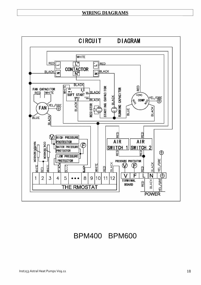
WIRING DIAGRAMS
BPM400 BPM600

Inst253 Astral Heat Pumps V09.11 19
WIRING DIAGRAMS
BPM700 BPM800

Inst253 Astral Heat Pumps V09.11 20
WIRING DIAGRAMS
BPT900

Inst253 Astral Heat Pumps V09.11 21
WARRANTY AstralPool Australia Pty Ltd (ABN 97 007 284 504) ("AstralPool") provides the following warranty in relation to its BP Series Heat Pumps ("Product"). Our goods come with guarantees that cannot be excluded under the Australian Consumer Law. You are entitled to a replacement or refund for a major failure and for compensation for any other reasonably foreseeable loss or damage. You are also entitled to have the goods repaired or replaced if the goods fail to be of acceptable quality and the failure does not amount to a major failure. The benefits of this warranty are in addition to any rights and remedies imposed by Australian State and Federal legislation that cannot be excluded. Nothing in this warranty is to be interpreted as excluding, restricting or modifying any State or Federal legislation applicable to the supply of goods and services which cannot be excluded, restricted or modified. WARRANTY AstralPool warrants that, subject to the exclusions and limitations below, the Product will be free from defects in materials and workmanship during the warranty period. The warranty periods are set out below and commence 30 days after the date of purchase (to allow for installation). The warranty period may vary for different parts of the Product.
Parts Warranty Period
Titanium heat exchange 10 years
Compressor and evaporator 3 years
Thermostat, switches and all other components
12 months
If a defect appears in the Product before the end of the warranty period and AstralPool finds the Product to be defective in materials or workmanship, AstralPool will, in its sole discretion, either: (a) replace or repair the Product or the defective part of the Product free of charge; or (b) Cause the Product or the defective part of the Product to be replaced or repaired by an
Authorised AstralPool Service Agent free of charge. AstralPool reserves the right to replace defective parts of the Product with parts and components of similar quality, grade and composition where an identical part or component is not available. Goods presented for repair may be replaced by refurbished goods of the same type rather than being repaired. Refurbished parts may be used to repair the goods. WARRANTY CLAIMS 1. If a fault covered by warranty occurs, the customer must first contact AstralPool at the contact
address listed below, or an Authorised AstralPool Service Agent. 2. Any warranty claim must be accompanied by: (a) proof of purchase; (b) full details of the alleged defect; and (c) appropriate documentation (such as historical and maintenance records). 3. The customer must make the Product available to AstralPool or its Authorised AstralPool
Service Agent for inspection and testing. AstralPool or its Authorised AstralPool Service Agent will attend the premises where the Product is installed for inspection and testing. If the Product is installed:
(a) outside a capital city metropolitan area; and (b) is not within a 20 km radius of an Authorised AstralPool Service Agent; then the customer may have to pay a travel fee.

Inst253 Astral Heat Pumps V09.11 22
4. If such inspection and testing finds no defect in the Product, the customer must pay AstralPool's usual costs of service work and testing. If such inspection and testing finds a defect that is not covered by this warranty, the customer must pay AstralPool's usual costs of service work plus any parts and labour required to repair the Product, unless recoverable from AstralPool on the failure of any statutory guarantee under the ACL.
Exclusions The warranty will not apply where: (a) the customer is in breach of the Terms and Conditions of Sale; (b) the Product was used for a purpose other than one it was intended for; (c) the Product was repaired, modified or altered by any person other than AstralPool; (d) the Product has not been installed, maintained and/or operated in complete compliance with
the installation and operating instructions and any instructions by AstralPool; (e) the Product has been subject to accident, negligence, alteration, abuse or misuse. The warranty does not extend to: a) normal wear and tear; b) weather and other environmental conditions including but not limited to storm, flood, and/or
heat wave damage; or c) service and maintenance items. Examples of exclusions include but are not limited to:
incorrect water chemistry
incorrect power supply / connection Commercial Installations On commercial installations, such as health clubs, motels/hotels and hydrotherapy facilities, the warranty is limited to parts and in field labour (within capital city metropolitan areas or 20 km radius of Authorised AstralPool Service Agents) for a period of 12 months from the date of purchase plus 30 days to allow for installation. LIMITATIONS AstralPool makes no express warranties or representations other than set out in this warranty. The repair or replacement of the Product or part of the Product is the absolute limit of AstralPool's liability under this express warranty.

Inst253 Astral Heat Pumps V09.11 23

Inst253 Astral Heat Pumps V09.11 24
ASTRALPOOL Pty. Limited. A.B.N. 97 007 284 504
www.astralpool.com.au email: [email protected]
Information and specifications subject to change without notice.
Victoria: New South Wales: Queensland: South Australia: Western Australia: Gold Coast: Townsville:
Ph: (03) 8796 8600 Ph: (02) 9853 2100 Ph: (07) 3308 5400 Ph: (08) 8152 7600 Ph: (08) 9350 2600 Ph: (07) 5552 2600 Ph: (07) 4750 3100
Fax: (03) 8796 8670 Fax: (02) 98532170 Fax: (07) 3308 5470 Fax: (08) 81527670 Fax: (08) 9350 2670 Fax: (07) 5552 2670 Fax: (07) 4750 3170
INSTALLATION AND OPERATING INSTRUCTIONS I INSTALLATION AND OPERATING INSTRUCTIONS