astm e647 fcg testing standard final report · 2011-05-14 · usafa tr 2006-10 astm e647 fcg round...
TRANSCRIPT
USAFA TR 2006-10
ASTM E647 FCG Testing Standard
Round Robin Fatigue Crack Growth Testing Results
Final Report
Jason Avram
Center for Aircraft Structural Life Extension (CAStLE)Department of Engineering Mechanics
HQ USAFA/DFEM2354 Fairchild Drive, Suite 6L-155USAF Academy CO 80840-6240(719) 333-6266, DSN 333-6266
November 2006
APPROVED FOR PUBLIC RELEASE; DISTRIBUTION UNLIMITED
A ,f7
DEAN OF THE FACULTYUNITED STATES AIR FORCE ACADEMY
COLORADO 80840
20061109075
Coordination and Approval
This article, Stress Corrosion Cracking and Repairs for Fuselage Skin Structures, ispresented as a competent treatment of the subject, worthy of publication. The UnitedStates Air Force Academy vouches for the quality of the research, without necessarilyendorsing the opinions and conclusions of thejauthor: Therefore, the viewvs expressed inthis article hfre tbose of fhe author Ind .do not reflect the officTI policy or position of theUnited States Air Force, Department of Defense, or the US Government.
This report has been cleared for publication and released for unlimited
distribution.
Prepared by:
~~~~~~~~. ..... ..':' ' 2 -. i• ... . '
JASON B. AVRAM, Maj, USAF 1 November 2006Deputy Director for Research DateCenter for Aircraft Structural Life Extension
The report has been reviewed and is approved for publication.
SCOTT A. FAWAZ, Lt Col SAF 1 November 2006Director DateCenter for Aircraft Structura ife Extension
USAFA TR 2006-10
ASTM E647 FCG Round Robin TestingCenter for Aircraft Structural Life Extension (CAStLE) Lab
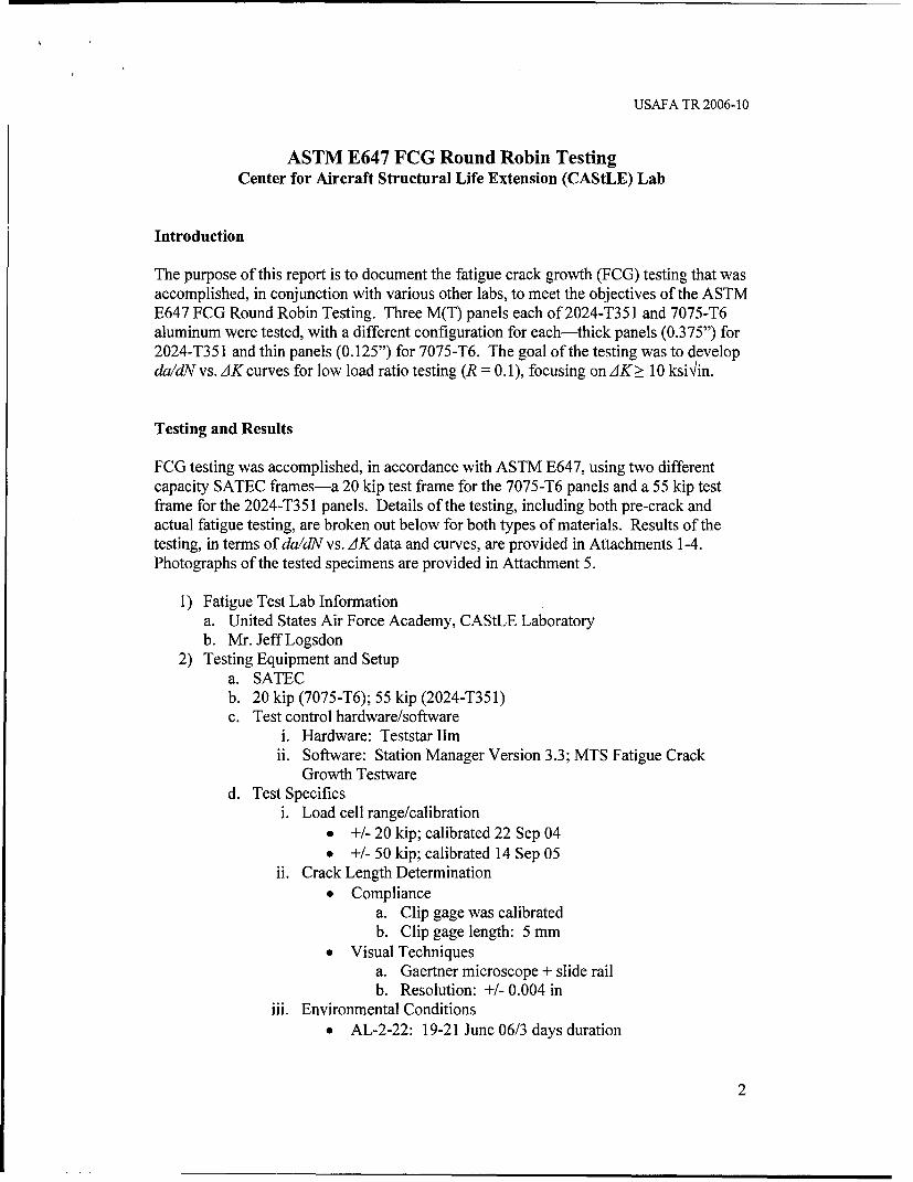
Introduction
The purpose of this report is to document the fatigue crack growth (FCG) testing that wasaccomplished, in conjunction with various other labs, to meet the objectives of the ASTME647 FCG Round Robin Testing. Three M(T) panels each of2024-T351 and 7075-T6aluminum were tested, with a different configuration for each-thick panels (0.375") for2024-T351 and thin panels (0.125") for 7075-T6. The goal of the testing was to developda/dN vs. AK curves for low load ratio testing (R = 0.1), focusing on AK > 10 ksi/in.
Testing and Results
FCG testing was accomplished, in accordance with ASTM E647, using two differentcapacity SATEC frames-a 20 kip test frame for the 7075-T6 panels and a 55 kip testframe for the 2024-T351 panels. Details of the testing, including both pre-crack andactual fatigue testing, are broken out below for both types of materials. Results of thetesting, in terms of da/dN vs. AK data and curves, are provided in Attachments 1-4.Photographs of the tested specimens are provided in Attachment 5.
1) Fatigue Test Lab Informationa. United States Air Force Academy, CAStLE Laboratoryb. Mr. Jeff Logsdon
2) Testing Equipment and Setupa. SATECb. 20 kip (7075-T6); 55 kip (2024-T351)c. Test control hardware/software
i. Hardware: Teststar Ilmii. Software: Station Manager Version 3.3; MTS Fatigue Crack
Growth Testwared. Test Specifics
i. Load cell range/calibration
* +/- 20 kip; calibrated 22 Sep 04* ±/- 50 kip; calibrated 14 Sep 05
ii. Crack Length Determination"* Compliance
a. Clip gage was calibratedb. Clip gage length: 5 mm
"• Visual Techniquesa. Gaertner microscope + slide railb. Resolution: +/- 0.004 in
iii. Environmental Conditions* AL-2-22: 19-21 June 06/3 days duration
2

USAFA TR 2006-10
a. Temperature-26°Cb. Humidity-24%
"* AL-2-29: 22-23 June 06/2 days durationa. Temperature-26*Cb. Humidity-24%
"* AL-2-30: 26-27 June 06/2 days durationa. Temperature-260 Cb. Humidity-24%
"* AL-7-32: 17-18 May 05/2 days durationa. Temperature-28*Cb. Humidity-15%
"* AL-7-33: 18-19 May 05/2 days durationa. Temperature-29°Cb. Humidity-16%
"* AL-7-34: 23-24 May 05/2 days durationa. Temperature-31 0Cb. Humidity-20%
iv. Grips-M(T) Geometry"* Grip-to-Grip distance - required that Gage Length > 6
inches was required"* Applied strain gages to verify that no significant bending
stress was present in test frame for 2024-T351 testing3) Specimen Details
a. Materiali. 2024-T351 Aluminum: cracks checked visually, E not needed
ii. 7075-T6 Aluminum: E = 9.5 x 10³ Ksib. Specimen Geometry
i. M(T) Fatigue Crack Growth Specimens* E647 stress intensity solution was not used. The following
stress intensity solution was used, where AK = K,,,m - Kmi,:
a. K= FSg-ffa1 - 0.5a + 0.326ao2 a
b. -,--awhere: bii. Dimensions
"* Width (W); Thickness (B)a. 2024-T351: W = 4in; B = 0.375 inb. 7075-T6: W = 4 in; B = 0.125 in
"* Notch Length = 0.80 in"* Notch Height = 0.01 in"* Crack Length Transducer location and dimensions
a. Crack length transducer was centered and locateddirectly above the EDM notch
b. Transducer was positioned with one holeapproximately 0.30" above and below the EDMnotch
3
USAFA TR 2006-10
iii. Specimen Preparation"* Specimen surfaces were minimually polished with a
machine buffer to facilitate visual crack lengthmeasurements
"* EDM notch was used"* Specimens were cut in length to facilitate the minimum
gage length > 1.5 W; therefore gage length = 6 inchesbetween grip holes
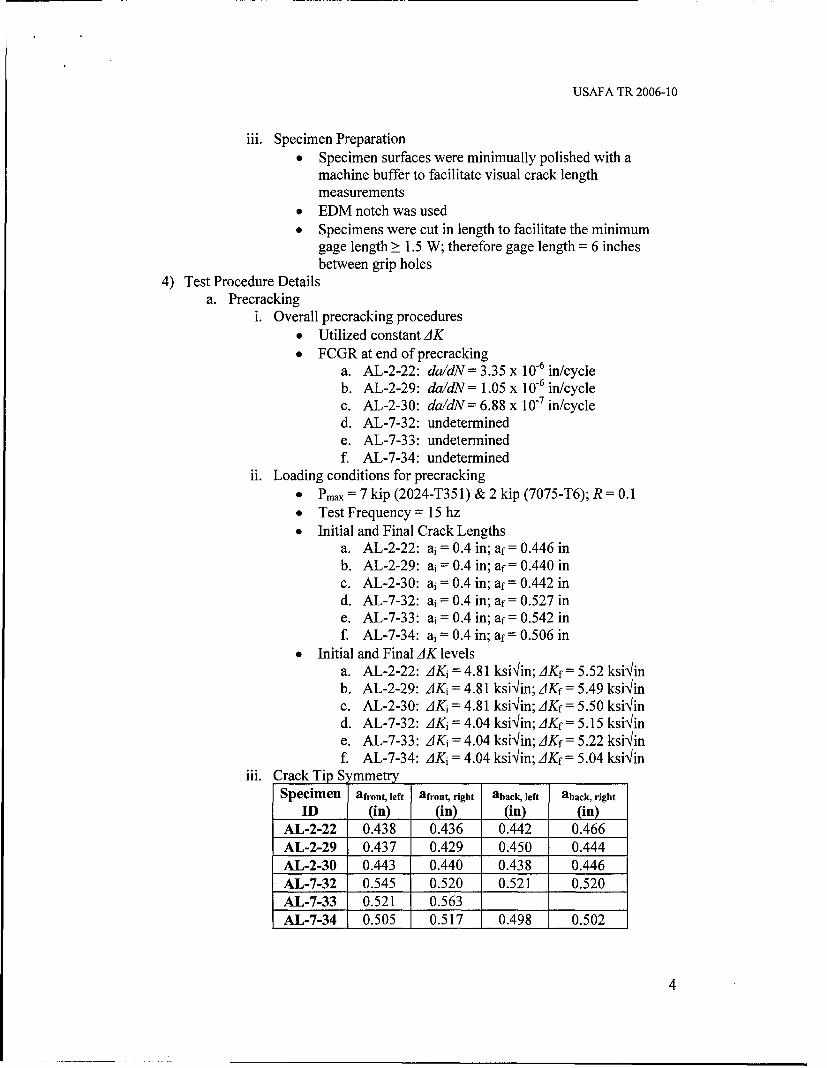
4) Test Procedure Detailsa. Precracking
i. Overall precracking procedures"* Utilized constant AK"* FCGR at end of precracking
a. AL-2-22: da/dN = 3.35 x 10⁻⁶ in/cycleb. AL-2-29: da/dN= 1.05 x 10⁻⁶ in/cyclec. AL-2-30: da/dN= 6.88 x 10⁻⁷ in/cycled. AL-7-32: undeterminede. AL-7-33: undeterminedf. AL-7-34: undetermined
ii. Loading conditions for precracking"* Pmax = 7 kip (2024-T351) & 2 kip (7075-T6); R = 0.1"* Test Frequency = 15 hz"* Initial and Final Crack Lengths
a. AL-2-22: ai = 0.4 in; af = 0.446 inb. AL-2-29: ai = 0.4 in; af = 0.440 inc. AL-2-30: ai = 0.4 in; af = 0.442 ind. AL-7-32: ai = 0.4 in; af = 0.527 ine. AL-7-33: ai = 0.4 in; af = 0.542 inf. AL-7-34: ai = 0.4 in; af = 0.506 in
"* Initial and Final AK levelsa. AL-2-22: AKi = 4.81 ksi•/in; AKf= 5.52 ksi'iinb. AL-2-29: AKi = 4.81 ksi/in; AKf = 5.49 ksi'iinc. AL-2-30: AKi = 4.81 ksi/in; AKf = 5.50 ksi\Iind. AL-7-32: AKi = 4.04 ksi•Iin; AKf = 5.15 ksi'Iine. AL-7-33: AKi = 4.04 ksi/in; AKf= 5.22 ksi'linf. AL-7-34: AKi = 4.04 ksi4in; AKf = 5.04 ksi4in
iii. Crack Tip SymmetrySpecimen afront, left afront, right aback, left aback, right
ID (in) (in) (in) (in)AL-2-22 0.438 0.436 0.442 0.466AL-2-29 0.437 0.429 0.450 0.444AL-2-30 0.443 0.440 0.438 0.446AL-7-32 0.545 0.520 0.521 0.520AL-7-33 0.521 0.563AL-7-34 0.505 0.517 0.498 0.502
4

USAFA TR 2006-10
b. Fatigue Crack Growth Testingi. Approach
"* Constant Amplitude: 2024-T351 panelsa. Pmax = 10.5 kip; R = 0.1; Frequency = 15 hzb. Initial and Final Crack Lengths
i. AL-2-22: ai = 0.446 in; af = 1.642 inii. AL-2-29: ai = 0.440 in; af = 1.646 in
iii. AL-2-30: ai = 0.442 in; af = 1.631 inc. Initial and Final AK levels
i. AL-2-22: AK1 = 5.52 ksi/in; AKf = ksi•inii. AL-2-29: AK1 = 5.49 ksi'Iin; AKf = ksiin
iii. AL-2-30: AKi = 5.50 ksi4in; AKf = ksi4ind. Aa/W crack length intervals for data points
i. Aa < 0.03W for 2a/W < 0.60ii. Aa < 0.02W for 2a/W > 0.60
e. visual crack length intervals and number of visualstaken, and crack tip symmetry are included asAttachment 1.
" K-control-7075-T6 panelsa. Initial Stress intensity
i. AL-7-32: Kintiai = 5.21 ksi'Iinii. AL-7-33: Kitial = 4.82 ksi'lin
iii. AL-7-34: Kiitiai = 5.48 ksi\'inb. Normalized K-gradient-2.5c. R = 0.1; Frequency = 15 hzd. Initial and Final Crack Lengths
i. AL-7-32: ai = 0.527 in; af= 1.351 inii. AL-7-33: ai = 0.542 in; af= 1.615 in
iii. AL-7-34: ai = 0.506 in; af= 1.376 ine. Aa/W crack length intervals for data points-it
appears to be 0.005f. Crack length data included as Attachment 2
5) Analysis Technique (post-test processing)a. Automated/manual
i. 2024-T351-manual, using
"* K = FSgV-4I1 - 0.5oa + 0.2cza
"• F= 0.326a 2 where: a=-
ii. 7075-T6-automated, utilizing MTS Fatigue Crack GrowthTestware
b. Method used: Secant methodc. Crack front profile and final crack length measurements are included in
Attachments 3 and 4d. Possible error between visual crack lengths and transducer crack lengths
was not investigated
5
USAFA TR 2006-10
e. No fracture surface appearance anomalies were observedf. Validation of yield criteria for both materials was determined, in
accordance with ASTM E647
This concludes CAStLE's portion of the round robin testing. For any questions orconcerns, please feel free to contact me.
Maj Jason AvramCAStLE Deputy for Research
Attachments:1. 2024-T351 Crack Growth Data2. 7075-T6 Crack Growth Data3. 2024-T351 da/dN Data4. 7075-T6 da/dN Data5. Photograph of Tested FCG Panels
6
USAFA TR 2006-10
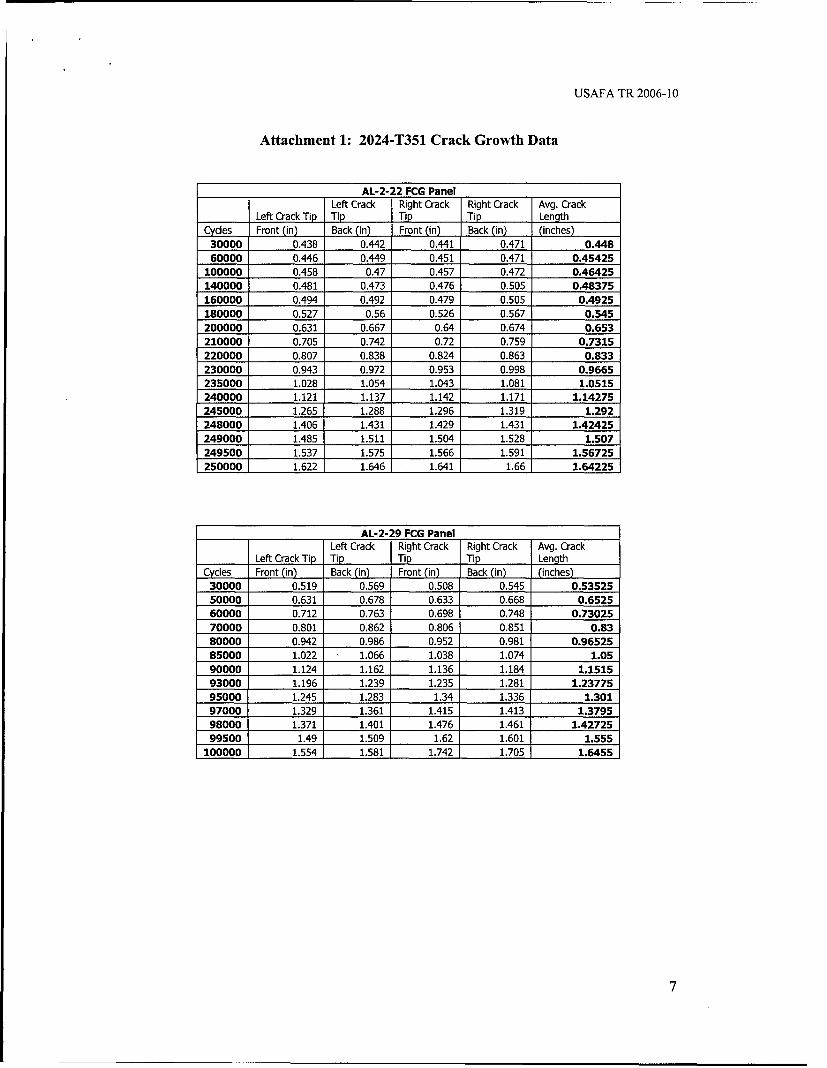
Attachment 1: 2024-T351 Crack Growth Data
AL-2-22 FCG PanelLeft Crack Right Crack Right Crack Avg. Crack
Left Crack Tip Tip Tip Tip LengthCycles Front (in) Back (in) Front (in) Back (in) (inches)30000 0.438 0.442 0.441 0.471 0.44860000 0.446 0.449 0.451 0.471 0.45425
100000 0.458 0.47 0.457 0.472 0.46425140000 0.481 0.473 0.476 0.505 0.48375160000 0.494 0.492 0.479 0.505 0.4925180000 0.527 0.56 0.526 0.567 0.545200000 0.631 0.667 0.64 0.674 0.653210000 0.705 0.742 0.72 0.759 0.7315220000 0.807 0.838 0.824 0.863 0.833230000 0.943 0.972 0.953 0.998 0.9665235000 1.028 1.054 1.043 1.081 1.0515240000 1.121 1.137 1.142 1.171 1.14275245000 1.265 1.288 1.296 1.319 1.292248000 1.406 1.431 1.429 1.431 1.42425249000 1.485 1.511 1.504 1.528 1.507249500 1.537 1.575 1.566 1.591 1.56725250000 1.622 1.646 1.641 1.66 1.64225
AL-2-29 FCG PanelLeft Crack Right Crack Right Crack Avg. Crack
Left Crack Tip Tip Tip Tip LengthCycles Front (in) Back (in) Front (in) Back (in) (inches)
30000 0.519 0.569 0.508 0.545 0.5352550000 0.631 0.678 0.633 0.668 0.652560000 0.712 0.763 0.698 0.748 0.7302570000 0.801 0.862 0.806 0.851 0.8380000 0.942 0.986 0.952 0.981 0.9652585000 1.022 1.066 1.038 1.074 1.0590000 1.124 1.162 1.136 1.184 1.151593000 1.196 1.239 1.235 1.281 1.2377595000 1.245 1.283 1.34 1.336 1.30197000 1.329 1.361 1.415 1.413 1.379598000 1.371 1.401 1.476 1.461 1.4272599500 1.49 1.509 1.62 1.601 1.555
100000 1.554 1.581 1.742 1.705 1.6455
7
USAFA TR 2006-10
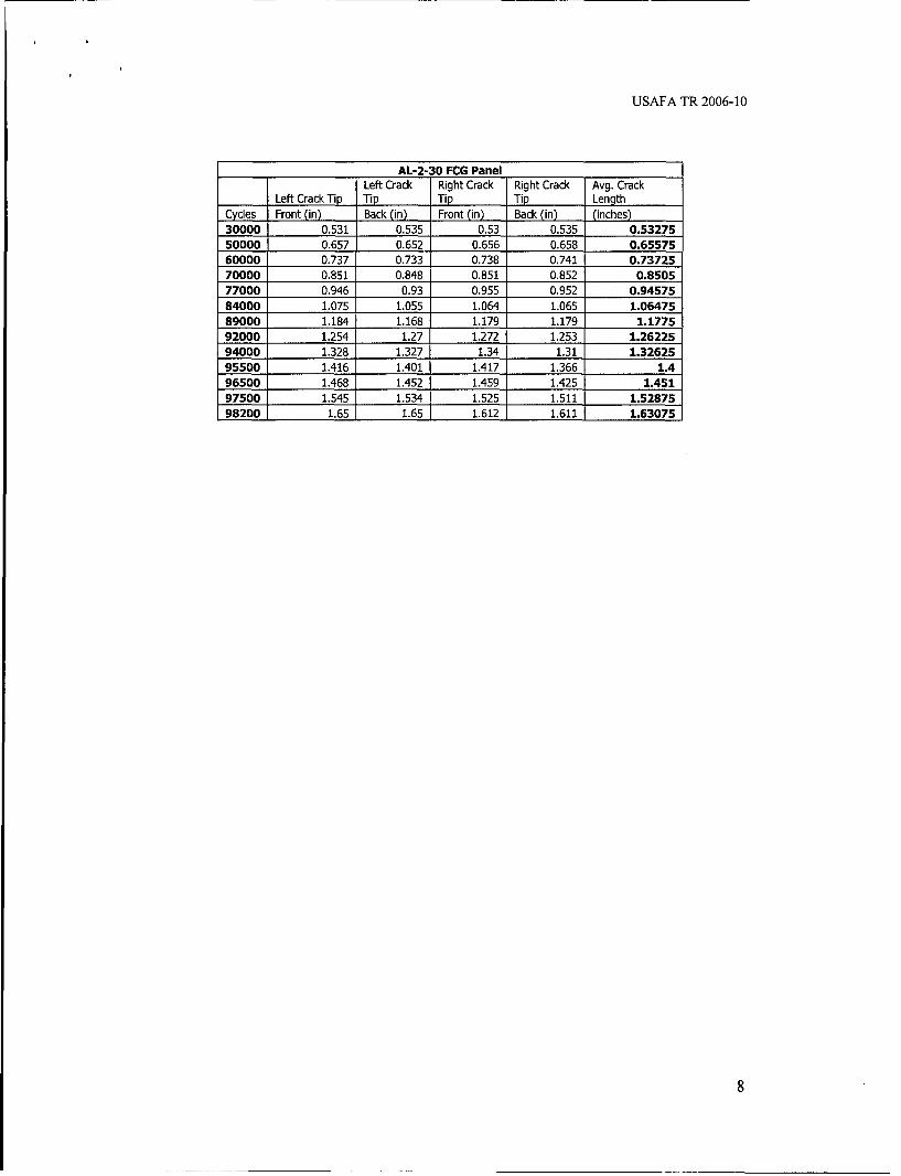
AL-2-30 FCG PanelLeft Crack Right Crack Right Crack Avg. Crack
Left Crack Tip Tip Tip Tip LengthCycles Front (in) Back (in) Front (in) Back (in) (inches)30000 0.531 0.535 0.53 0.535 0.5327550000 0.657 0.652 0.656 0.658 0.6557560000 0.737 0.733 0.738 0.741 0.7372570000 0.851 0.848 0.851 0.852 0.850577000 0.946 0.93 0.955 0.952 0.9457584000 1.075 1.055 1.064 1.065 1.0647589000 1.184 1.168 1.179 1.179 1.177592000 1.254 1.27 1.272 1.253 1.2622594000 1.328 1.327 1.34 1.31 1.3262595500 1.416 1.401 1.417 1.366 1.496500 1.468 1.452 1.459 1.425 1.45197500 1.545 1.534 1.525 1.511 1.5287598200 1.65 1.65 1.612 1.611 1.63075
8

USAFA TR 2006-10
Attachment 2: 7075-T6 Crack Growth Data
AL-7-32 FCG Panel AL-7-33 FCG Panel AL-7-34 FCG PanelCrack Length Crack Length Crack Length
Cycles (in) Cycles (in) Cycles (in)
75 0.530343 83 0.515134 96 0.556429
22113 0.551661 11832 0.535358 38175 0.57677249194 0.572579 41057 0.555382 64964 0.59737468391 0.592614 72653 0.575512 86495 0.61814281697 0.613032 95415 0.596917 101346 0.63816593187 0.634543 115222 0.617358 111140 0.658311
105072 0.65485 131794 0.637398 120179 0.67985114599 0.675476 144841 0.657693 126684 0.700846123658 0.695524 155628 0.67935 132231 0.720882129597 0.716402 166158 0.699689 135988 0.741035135786 0.736402 174511 0.719705 139466 0.761484141082 0.756949 181515 0.740677 142268 0.781898145107 0.778059 186471 0.761138 145230 0.80213148547 0.799118 191126 0.781681 147551 0.823181151846 0.819362 195441 0.802004 149983 0.843949154248 0.840063 198964 0.822173 152117 0.865169156557 0.860843 202117 0.842248 154029 0.885622
158919 0.881811 204996 0.862382 155673 0.905949161370 0.901909 207440 0.882894 157145 0.926028163212 0.922331 209667 0.902969 158383 0.946555164935 0.942488 211349 0.92335 159672 0.966595166471 0.962539 213070 0.943701 160775 0.987567167723 0.983091 214582 0.963811 161845 1.00763169161 1.00365 216067 0.984673 162706 1.02771170283 1.02392 217362 1.00498 163502 1.04822171465 1.04404 218499 1.02552 164295 1.06836
172449 1.0642 219573 1.04588 165052 1.08889173267 1.08519 220564 1.0659 165790 1.10898174091 1.10581 221493 1.08591 166409 1.12938174821 1.12678 222404 1.10669 167025 1.14946175451 1.14682 223277 1.12748 167616 1.17054176019 1.16692 224037 1.148 168160 1.19067176530 1.18706 224701 1.16835 168621 1.21069176898 1.20709 225289 1.18846 169098 1.23107177293 1.22713 225746 1.20853 169537 1.25117177608 1.24745 226163 1.22886 169875 1.27124177863 1.26753 226537 1.24943 170134 1.29141178060 1.28811 226810 1.2698 170363 1.31268178241 1.3088 227025 1.29014 170542 1.33492178376 1.33009 227215 1.31018 170673 1.35555178481 1.35062 227346 1.33101 170772 1.37597
227467 1.35103
227564 1.38501
227737 1.40632227821 1.42876227873 1.45004
227915 1.4739
227948 1.49939227971 1.52209227982 1.54669
S228005 1.61511
9
USAFA TR 2006-10
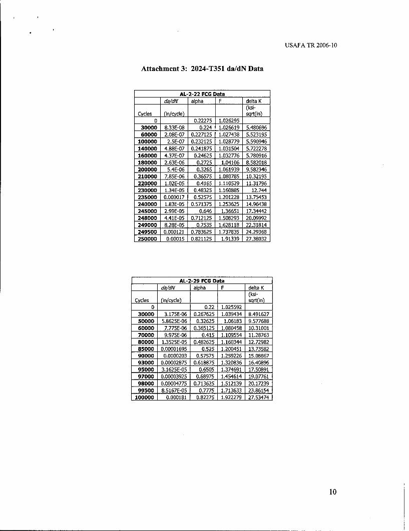
Attachment 3: 2024-T351 da/dN Data
AL-2-22 FCG Datada/dN alpha F delta K
(ksi-Cycles (in/cycle) sqrt(in)
0 0.22275 1.02629530000 8.33E-08 0.224 1.026619 5.48069660000 2.08E-07 0.227125 1.027438 5.523195
100000 2.5E-07 0.232125 1.028779 5.590946140000 4.88E-07 0.241875 1.031504 5.722278160000 4.37E-07 0.24625 1.032776 5.780916180000 2.63E-06 0.2725 1.04106 8.582018200000 5.4E-06 0.3265 1.061939 9.582346210000 7.85E-06 0.36575 1.080785 10.32195220000 1.02E-05 0.4165 1.110529 11.31796230000 1.34E-05 0.48325 1.160885 12.744235000 0.000017 0.52575 1.201228 13.75453240000 1.83E-05 0.571375 1.253625 14.96438245000 2.99E-05 0.646 1.36651 17.34442248000 4.41E-05 0.712125 1.508293 20.09992249000 8.28E-05 0.7535 1.628118 22.31814249500 0.000121 0.783625 1.737835 24.29368250000 0.00015 0.821125 1.91339 27.38032
AL-2-29 FCG Datada/dN alpha F delta K
(ksi-Cycles (in/cycle) sqr(in)
0 0.22 1.02559230000 3.175E-06 0.267625 1.039434 8.49162750000 5.8625E-06 0.32625 1.06183 9.57768860000 7.775E-06 0.365125 1.080458 10.3100170000 9.975E-06 0.415 1.109554 11.2876380000 1.3525E-05 0.482625 1.160344 12.7298285000 0.00001695 0.525 1.200451 13.7358290000 0.0000203 0.57575 1.259226 15.0886793000 0.00002875 0.618875 1.320836 16.4089695000 3.1625E-05 0.6505 1.374691 17.5089197000 0.00003925 0.68975 1.454614 19.0776198000 0.00004775 0.713625 1.512139 20.1723999500 8.5167E-05 0.7775 1.713633 23.86154
100000 0.000181 0.82275 1.922279 27.53474
10

USAFA TR 2006-10
AL-2-30 FCG Data
da/dN alpha F delta K(ksi-
Cycles (in/cycle) sqrt(in)30000 0.266375 1.03902450000 6.15E-06 0.327875 1.062544 9.60797160000 8.15E-06 0.368625 1.0823 10.3769770000 1.13E-05 0.42525 1.116347 11.4961477000 1.36E-05 0,472875 1.152095 12.5109984000 0.000017 0.532375 1.208205 13.9213189000 2.26E-05 0.58875 1.276533 15.46779
92000 2.83E-05 0.631125 1.340723 16.8200594000 3.2E-05 0.663125 1.398653 17.9861495500 4.92E-05 0.7 1.478376 19.5328
96500 5.1E-05 0.7255 1.543802 20.7654297500 7.78E-05 0.764375 1.66515 22.989998200 0.000146 0.815375 1.88291 26.84966
2024-T3510.00111 4 ------ - -- - - 4- - -- -- -- -- - -- -- -- ,
" I --- T - - - - - -I-- - ---
- -AI-2-29 - - - - -- -- - -. - . - _ -- ---- _ - , r ,
I I I I[I I I I I I I
I I I I I I I I I I I I"-"-- A I-22 2 - - -- - - - -_--- - - ---- - - - - - - --- . . --- - - -_ -
SI I I I I I I I I I
I I I I I F I I I I I I I
0 . 00 I I I I I 1 I I I I 1 I I I
S- - " -- -- -- --- ------- -- - - - ---
U I I I I I _ Z _ -•_ ZII I • , - -'I I I I
I I I i I I I I I I
I I L - . .- ---- -------- -
SI I I I I I I I I I I
1. I I I I I I I I I I I II -I I I -I I I I I I
0 0 0 1I ,I I I , I , I , I I I lI - - - I T " r I I I I I
-• -I . . . . •L -- --- - - -. ..• - - . .J I-- - -L - - -- - - -• f -" I
- I - -I I I - IL I1 - LI
I I ! I II I I I
0.000001 1 ! _I I I ! 11
1 0 100
log delta K (Ksi-sqrt(in))
-4-- ---- ---- -- ~ - -- -
USAFA TR 2006-10
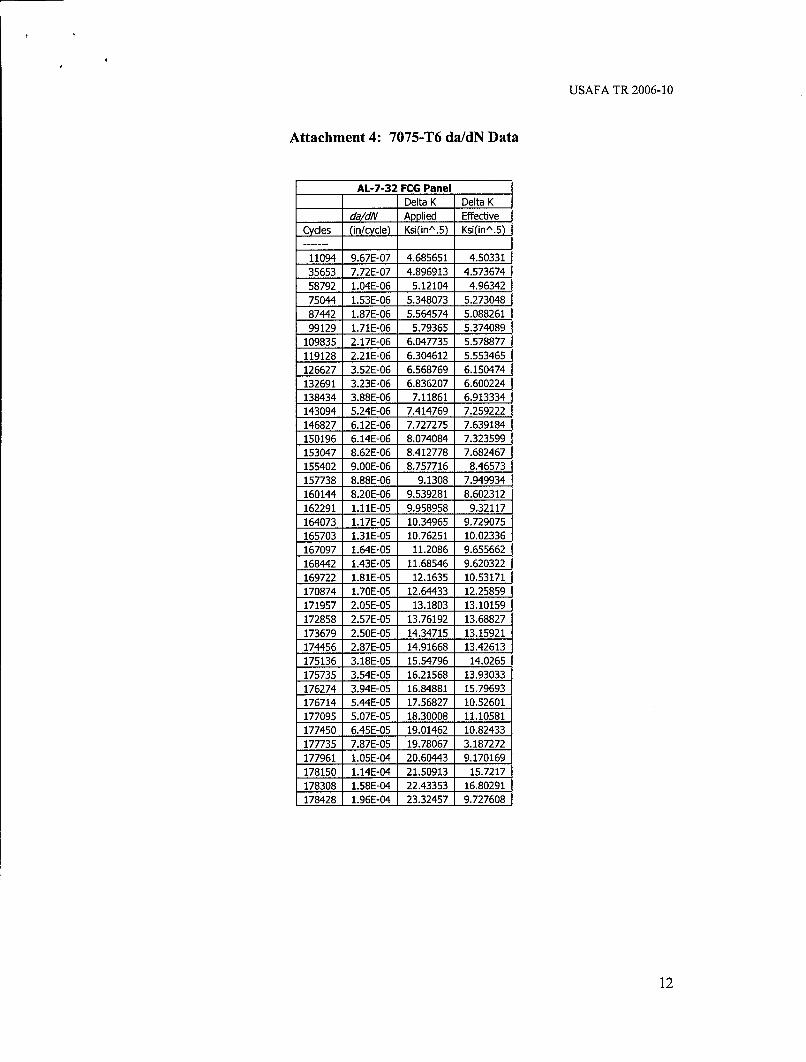
Attachment 4: 7075-T6 da/dN Data
AL-7-32 FCG Panel
Delta K Delta K
da/dN Applied EffectiveCycles (in/cycle) Ksi(inA.5) Ksi(inA.5)
11094 9.67E-07 4.685651 4.5033135653 7.72E-07 4.896913 4.57367458792 1.04E-06 5.12104 4.9634275044 1.53E-06 5.348073 5.273048
87442 1.87E-06 5.564574 5.08826199129 1.71E-06 5.79365 5.374089
109835 2.17E-06 6.047735 5.578877119128 2.21E-06 6.304612 5.553465
126627 3.52E-06 6.568769 6.150474132691 3.23E-06 6.836207 6.600224138434 3.88E-06 7.11861 6.913334143094 5.24E-06 7.414769 7.259222
146827 6.12E-06 7.727275 7.639184150196 6.14E-06 8.074084 7.323599153047 8.62E-06 8.412778 7.682467155402 9.OOE-06 8.757716 8.46573157738 8.88E-06 9.1308 7.949934
160144 8.20E-06 9.539281 8.602312162291 1.11E-05 9.958958 9.32117164073 1.17E-05 10.34965 9.729075165703 1.31E-05 10.76251 10.02336
167097 1.64E-05 11.2086 9.655662168442 1.43E-05 11.68546 9.620322
169722 1.81E-05 12.1635 10.53171170874 1.70E-05 12.64433 12.25859171957 2.05E-05 13.1803 13.10159172858 2.57E-05 13.76192 13.68827173679 2.50E-05 14.34715 13.15921174456 2.87E-05 14.91668 13.42613175136 3.18E-05 15.54796 14.0265175735 3.54E-05 16.21568 13.93033
176274 3.94E-05 16.84881 15.79693176714 5.44E-05 17.56827 10.52601177095 5.07E-05 18.30008 11.10581
177450 6.45E-05 19.01462 10.82433177735 7.87E-05 19.78067 3.187272177961 1.05E-04 20.60443 9.170169178150 1.14E-04 21.50913 15.7217178308 1.58E-04 22.43353 16.80291
178428 1.96E-04 23.32457 9.727608
12

USAFA TR 2006-10
AL-7-33 FCG DataDelta K Delta K
da/dN Applied EffectiveCycles (in/cycle) Ksi(inA.5) Ksi(inA.5)
5957 1.72E-06 4.338151 2.7863326444 6.85E-07 4.631921 4.61269756855 6.37E-07 4.831874 4.80594584034 9.40E-07 5.019136 4.914727
105318 1.03E-06 5.21034 5.103054123508 1.21E-06 5.43792 5.317942
138317 1.56E-06 5.66596 5.494095150234 2.01E-06 5.908563 5.736698160893 1.93E-06 6.168259 5.912275170334 2.40E-06 6.430374 6.035476178013 2.99E-06 6.692574 6.391897183993 4.13E-06 6.974114 6.695711188798 4.41E-06 7.275338 6.824092193283 4.71E-06 7.586433 7.188312197202 5.73E-06 7.903917 7.142065200540 6.37E-06 8.232538 7.289641203556 6.99E-06 8.573045 7.910766206218 8.39E-06 8.914818 8.419771208553 9.01E-06 9.287326 8.620443210508 1.21E-05 9.67949 8.40095212209 1.18E-05 10.09623 8.72324213826 1.33E-05 10.51631 9.035658215324 1.40E-05 10.93532 9.610335216714 1.57E-05 11.39256 9.427794217930 1.81E-05 11.8689 9.441694219036 1.90E-05 12.3619 10.4557220068 2.02E-05 12.87347 10.98186221028 2.15E-05 13.41511 11.87713221948 2.28E-05 13.97439 11.90714222840 2.38E-05 14.53643 11.30726223657 2.70E-05 15.1505 12.9531224369 3.06E-05 15.72648 15.12409224995 3.42E-05 16.34124 15.58618225517 4.39E-05 17.05403 16.5643225954 4.88E-05 17.76336 16.04632226350 5.50E-05 18.53756 15.35086226673 7.46E-05 19.35717 16.14117226917 9.46E-05 20.1501 15.71137227120 1.05E-04 20.9451 15.1025227280 1.59E-04 21.83027 15.12699
227406 1.65E-04 22.74134 16.14365227515 3.50E-04 24.04489 20.91779227650 1.23E-04 25.45607 25.41955227779 2.67E-04 26.52318 21.47371227847 4.09E-04 27.59278 20.5018227894 5.68E-04 28.78767 23.26079227931 7.72E-04 30.14975 24.04207227959 9.87E-04 31.52479 28.99257227976 2.24E-03 32.77694 32.75794227993 2.98E-03 35.14425 35.08554
13
USAFA TR 2006-10
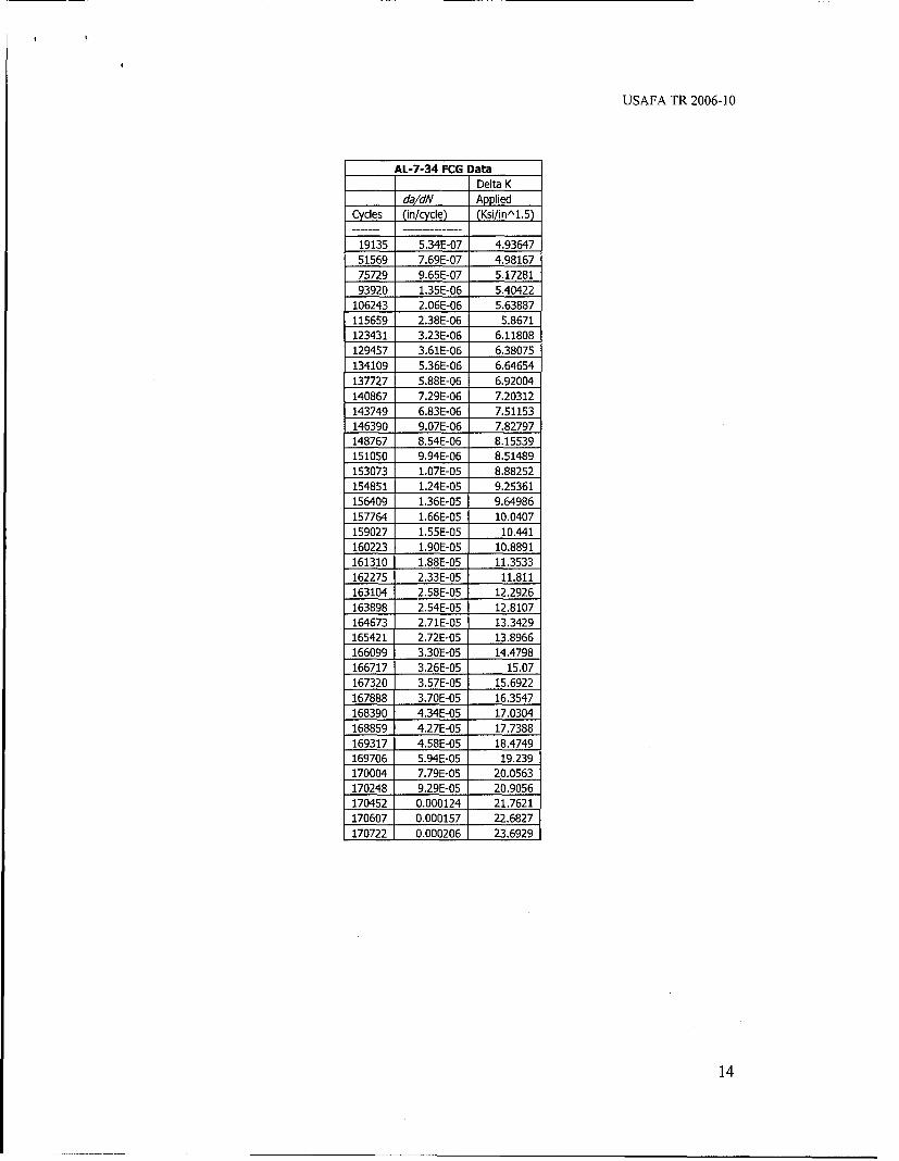
AL-7-34 FCG DataDelta K
da/dN AppliedCycles (in/cycle) (Ksi/inA1.5)
19135 5.34E-07 4.9364751569 7.69E-07 4.98167
75729 9.65E-07 5.1728193920 1.35E-06 5.40422
106243 2.06E-06 5.63887115659 2.38E-06 5.8671123431 3.23E-06 6.11808129457 3.61E-06 6.38075134109 5.36E-06 6.64654137727 5.88E-06 6.92004140867 7.29E-06 7.20312143749 6.83E-06 7.51153146390 9.07E-06 7.82797148767 8.54E-06 8.15539151050 9.94E-06 8.51489153073 1.07E-05 8.88252
154851 1.24E-05 9.25361156409 1.36E-05 9.64986
157764 1.66E-05 10.0407159027 1.55E-05 10.441160223 1.90E-05 10.8891161310 1.88E-05 11.3533162275 2.33E-05 11.811
163104 2.58E-05 12.2926163898 2.54E-05 12.8107164673 2.71E-05 13.3429165421 2.72E-05 13.8966166099 3.30E-05 14.4798166717 3.26E-05 15.07167320 3.57E-05 15.6922167888 3.70E-05 16.3547168390 4.34E-05 17.0304168859 4.27E-05 17.7388169317 4.58E-05 18.4749169706 5.94E-05 19.239170004 7.79E-05 20.0563
170248 9.29E-05 20.9056170452 0.000124 21.7621170607 0.000157 22.6827170722 0.000206 23.6929
14

USAFA TR 2006-10
7075-T61.OOE-03 G E4705- -- :r-- Z
:A.---7----------------------------9-E647 7075-A-7-3----------------
-t-E647 7075-AL-7-34 -h H --- h-- -II F- - - - - - - - - - I
r- r Ii r I T I I
1.OOE-04-------------------
D - - - Z r I r
- - - - -I- - - - - - - - -I-
I-2-r - I F - - - - - - -r - - - -r - T - I
* lODE-OSciizzzzzz
- T 1 F-
1 .--0- -0- --- -
IlODE--F F Fr -- T T F?1 10 100 - - - - -
lo -et K ( l-s---qrt -- r - I-n))r t r I
- - - - -- --'L L - -------- - - -1 5
USAFA TR 2006-10
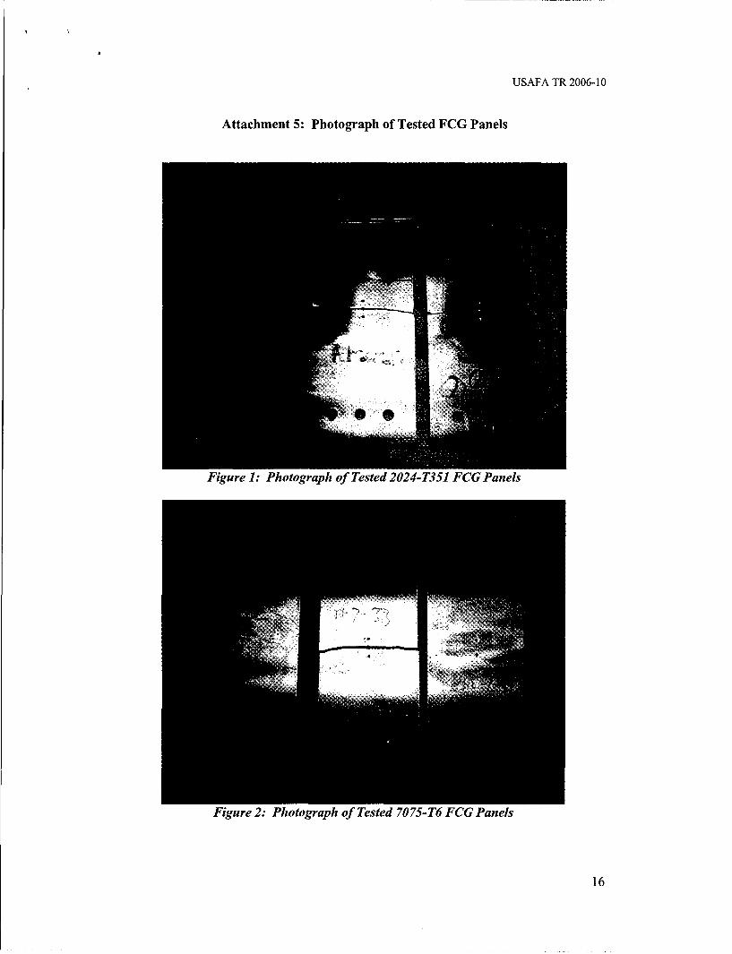
Attachment 5: Photograph of Tested FCG Panels
Figure 1: Photograph of Tested 2024-T351 FCG Panels
Figure 2: Photograph of Tested 7075-T6 FCG Panels
16

REPOT DCUMNTATON AGEForm Approved
1.RE OR REOTOAECUMM-YY) 2 EPOTATIPE 3.G DAEOMERE NFom 074-18
4en TITLEf ANDriý SUBITL sa CONTRACTte NUMyBERasý= o hs fetol0
4= re~olat sot tkc ir Fwatia 00Wni Gromwth o Tertino wcso Rrit', %Eb.Go n eatyfrf-I~ ocqn~ ihaRANeTinUMBER t 051 sla ur
i10M,8cvn~~~~rvnam~~Sc PRLGRAE ELEEN NONUMBERU OR EAOV DDES1. AUTHORTS DAT PROJ-Yý TTP 3 AE$CTOUMERE(Fo-T)
4, TILE AD SUBITLESa. COTASK NUMBER
5c. WROGRK M UN LEMBERTNME
7. PERFORMING ORGANIZATION NAME(S) AND ADDRESS(ES) S. PERFORMING ORGANIZATION REPORTNUMBER
Center for A44rcraft Stractlvrai Lif,"e Exteraiocn (CAStLE)DeOartn~ont of Enineering Mechanics, FIC US~.TA/DFFN 1DSA-FA-*rR-2006-1023-54 arhi Drive, Suite 2J2, U-SAF Academy CO) 80iS.10-6250
9, SPONSORING / MONITORING AGENCY NAME(S) AND ADD RESS (ES) 10. SPONSORJMONITOR'S ACRONYM(S)Southwest Research Instit-ute USwRT1San Por oden, TX _________________
11, SPONSORIMONITOR'S REPORTNUMBER(S)
12. DISTRIBUTION / AVAILABILITY STATEMENTDistribution A: Approved for public release, distribution unlimited.
13. SUPPLEMENTARY NOTES
14. ABSTRACTTepurpose of this report is to document the fatigue crack growth (FCG) testing that was accomplished. in conjunction with various other
labs, to meet the ob~jectives of the ASTM E647 ECO Round Robin Testing. Three M(T) panels cea of 2024-T351I and 7073-T6 aluminumwere tested., with a different configuration for each-thick panels (0.375") for 2024-T351I and thin panels (0.125") for 7075-T6. Thle goalof the testing was to develop da/d.Vvs. JK curves for low load ratio testing (R 0. 1). focusing on JK t 10 k-siin.
15. SUBJECT TERMSFatcicjue crack ro hA.STM, Testing standard, a/~ vs. LF
16. SECURITY CLASSIFICATION OF: 17. LIMITATION 18. NUMBER 1t9a, NAME OF RESPONSIBLE PERSONOF ABSTRACT OF PAGES 1Lt-Col Scott A. Pavmz
a. REPORT b. ABSTRACT c. THIS PAGE 1 9b. TELEPHONE NUMBER pou)dV wiiunclassified onclassi fied unclassifi'ed
Standard Farm 298 (Rev. 8.98)Ptvscribet by ANSI SW. Ms,48