astm e119-00a, 'fire tests of building construction ... · elmendorf, texas 78112-9784...
TRANSCRIPT

Page 1
ASTM El19-O00a
Fire Tests of Building Constructionand Materials*
APPENDIX R, ONE-HOUR FIRE RESISTIVE CONTROL CABLE TEST
Project No. 14980-119368, Revision I
*Modified in that the test specimen was not one that is described in thestandard, but the exposure was in accordance with the El 19 time-
temperature curve.
August 11, 2004
A Framatome ANP, Inc.,AR EVA an AREVA and Siemens company
58-5047207-01
Prepared for:AREVA
(Framatome ANP DE&S)6100 Southwest Blvd., Suite 400
Fort Worth, Texas 76109

Page 2
Abstract
This document describes the evaluation of an 8/C #12 AWG Meggitt Safety Systemselectrical cable and several support systems and attachment methods, when exposed tothe ASTM E119 time-temperature heating curve for a period exceeding one hour. Allsupports and connections remained firm and secure. Electrical testing was performedon the cable before, during and after the testing, and the minimum acceptance criteriawere met.
The details, procedures and observations reported herein are correct and true within the limits ofsound engineering practice. All specimens and test sample assemblies were produced, installedand tested under the surveillance of either the manufacturer's or the testing laboratory's in-houseQuality Assurance Program. This report describes the analysis of a distinct assembly and includesdescriptions of the test procedure followed, the assembly tested, and all results obtained. All testdata are on file and remain available for review by authorized persons.
Deggary N. Priest, PresidentAugnist 11. 2004Date
Reviewed and approved:
0 7-, %nQA Director Date: August 11. 2004
Omega Point Laboratories, Inc.16015 Shady Falls Road
Elmendorf, Texas 78112-9784210-635-8100 / FAX: 210-635-8101 / 800-966-5253
www.opl.com / e-mail: [email protected]. 0689-01

Project No. 14980-119368, Rev.1 FINAL REPORT August 11, 2004AREVA Page 3
TABLE OF CONTENTS
ITEM PAGE
INTRODUCTION 4TEST PROCEDURE 4
Horizontal Test Furnace 4Furnace Pressure 5Thermocouple Locations 6Data Acquisition Systems 6Correction Factor 6Hose Stream Test 7Acceptance Criteria (Excerpted from Test Plan) 7
TEST ASSEMBLY 8Test Slab 8Meggitt Safety Systems, Inc. (MSSI) Cable Installation 8
TEST RESULTS 9CONCLUSIONS 15
APPENDICESAppendix A: TEST PLAN & CONSTRUCTION DRAWINGS 16Appendix B: MEGGERING & CONDUCTOR RESISTANCE
RESULTS 37Appendix C: TEST DATA - FIRE EXPOSURE 51Appendix D: QUALITYASSURANCE 62Appendix E: PHOTOGRAPHS 127
LAST PAGE OF REPORT 132

Project No. 14980-119368, Rev.1AREVA
FINAL REPORT August 11, 2004
Page 4
INTRODUCTION
The objective of this test program was to demonstrate the performance of an 8/C #12 AWGMeggitt Safety Systems, Inc. fire resistive cable and cable support designs during a 1-hour fireexposure and following exposure to a hose stream test. The furnace temperatures, furnacethermocouples, Megger testing and hose stream testing were conducted in accordance withGeneric Letter 86-10 Supplement 1.
TEST PROCEDUREHorizontal Test Furnace
The 7' x 12' x 40" deep horizontal test furnace is designed to allow the specimen to be uniformlyexposed to the specified time-temperature conditions. It is fitted with 26 symmetrically-locateddiffuse-flame natural gas pipe burners designed to allow an even heat flux distribution across theunder surface of a horizontal test specimen. Furnace pressures may be maintained at any valuefrom +0.03" W.C. to -0.05" W.C. The furnace has been constructed so that the front (40" x 12')wall section can be removed to allow the evaluations of wall/ceiling interfaces and other specificapplications.
7' x 12' Horizontal Furnace (Plan View)
The temperature within the furnace is determined to be the mathematical average ofthermocouples located symmetrically within the furnace and positioned twelve inches away from

Project No. 14980-119368, Rev.lAREVA
FINAL REPORT August 11, 2004
Page 5
the horizontal face of the test specimen. The materials used in the construction of thesethermocouples are those suggested in the test standard. During the performance of a fire exposuretest, the furnace temperatures are recorded every 15 seconds and displayed for the furnaceoperator to allow control along the specified temperature curve. For report presentation purposes,the data is saved once per minute.
The fire exposure is controlled to conform with the standard time-temperature curve shown inFigure 1, as determined by the table below:
C
a)
EU
E0)
25002250
20001750
15001250
1000
750500250
0
Time(min)
05
1020306090
120180240300360420480
Temperature(OF)
681000130014621550170017921850192520002075215022252300
0 60 120 180 240 300 360 420 480
Time (min)
Fiure 1
The furnace interior temperature during a test is controlled such that the area under the time-temperature curve is within 10% of the corresponding area under the standard time-temperaturecurve for 1 hour or less tests, 7.5% for those less than 2 hours and 5% for those tests of 2 hours ormore duration.
Furnace Pressure
The pressure differential between the inside of the furnace (as measured approximately 3/4" belowthe exposed surface of the test slab) and the laboratory ambient air was maintained at +0.01 inches

Project No. 14980-119368, Rev.1 FINAL REPORT August 11, 2004AREVA Page 6
of water column for the duration of the fire exposure test (after the first five minutes, during whichfurnace stabilization was achieved).
Thermocouple Locations
No temperatures were monitored within the heated area except for those used to monitor andcontrol the furnace interior temperature.
Data Acquisition Systems
The furnace control thermocouples were monitored by a 100 channel Yokogawa, Inc. ModelDarwin Data Acquisition Unit and a Macintosh computer. The computer was programmed inLabVIEW 5.0 to send the commands to the data acquisition system to sample the data input linesand to convert the raw data into a usable format for display on screen and storage as an ASCII tab-delimited text file. That files were then, after the test, imported into MS Excel for conversion touser units and tabular and graphical display.
Correction Factor
When the indicated resistance period is 1/2 h or over, determined by the average or maximumtemperature rise on the unexposed surface or within the test sample, or by failure under load, acorrection shall be applied for variation of the furnace exposure from that prescribed, where it willaffect the classifications by multiplying the indicated period by two thirds of the difference in areabetween the curve of average furnace temperature and the standard curve for the first three fourthsof the period and dividing the product by the area between the standard curve and a base line of680F (20'C) for the same part of the indicated period, the latter area increased by 3240F* min tocompensate for the thermal lag of the furnace thermocouples during the first part of the test. Fora fire exposure in the test higher than standard, the indicated resistance period shall be increasedby the amount of the correction. For a fire exposure in the test lower than standard, the indicatedresistance period shall be similarly decreased for fire exposure below standard. The correction isaccomplished by mathematically adding the correction factor, C, to the indicated resistance period.
Project No. 14980-119368, Rev.1 FINAL REPORT August 11, 2004AREVA Page 7
The correction can be expressed by the following equation:
C 21(A - A,)3(As+L)
where:
C correction in the same units as 1,I indicated fire-resistance period,
A = area under the curve of indicated average furnace temperature for the first threefourths of the indicated period,
As = area under the standard furnace curve for the same part of the indicated period, andL e lag correction in the same units as A and A, (540 F h or 30C *h (3240'F min or
1800'C * min))
Hose Stream Test
Immediately following the fire endurance test, a hose stream test was performed in accordancewith USNRC Generic Letter 86-10, Supplement 1, Enclosure 1, Section VI. The hose stream was"applied at random to all exposed surfaces of the test specimen through a 1-1/2" fog nozzle set at adischarge angle of 30 degrees with a nozzle pressure of not less than 75 psi and a minimumdischarge pressure of 75 gpm with the tip of the nozzle at a maximum of 5 feet from the testspecimen. Duration of the hose stream application is 5 minutes." Prior to the hose streamapplication, the laboratory ensured the correct angle spray pattern, pressure and flow was achievedthrough calibrated gauges and other equipment as required.
Acceptance Criteria (Excerpted from Test Plan)
3.0 ACCEPTANCE CRITERIA
3.1 The acceptance criteria for the cable supports is that the cable supports remain attached to the test slaband that the cable remains attached to the supports, and that there is no functionally adverse physicalinteraction between the cable support material and the cable test specimen during the fire endurance testand the hose stream test.
3.2 A minimum conductor to conductor or conductor to cable sheath (shield) insulation resistance (IR) valueof 5.7 megohms per foot is considered to be the test acceptance criteria. The cable IR values obtainedduring the fire test exposure and after application of the hose stream will be used to demonstrate thefunctional capability of FNP specific Appendix R control circuit applications.

Project No. 14980-119368, Rev.1 FINAL REPORT August 11, 2004AREVA Page 8
3.3 The acceptance criteria for the conductor resistance is to show that conductor has continuity before the firetest and after the fire hose test.
3.4 The seals used for closure of the openings in the test slab will be ceramic fiber and are not being tested orconsidered part of the test assembly.
TEST SPECIMEN CONSTRUCTION
Test Slab
An 8' x 13' x 8" thick normal weight concrete slab (used previously) was in excellent condition andhence was utilized in this project after being turned over and any holes filled with ready-mixconcrete. The slab was then cured at 350'F for one week, cooled and placed on a work stand. Itwas then cooled and the appropriate holes cored through to receive the cables and the all-threadrod used to attach some of the supports.
Meggitt Safety Systems, Inc. (MSSI) Cable Installation
Prior to installation in the test assembly, meggering tests were performed on all conductors in theMSSI cable in an 'as received' condition. Results of this testing can be found in Appendix B.
The support slab was cored and prepared as described in the drawings supplied by AREVA(Framatome-ANP, see Appendix A Test Plan), including the installation of the required supports.A single 8/C #12 AWG Meggitt Safety Systems cable was installed, as indicated in the drawings.The length of cable exposed to the furnace heat was 24' 2" (24.167 ft).
The cable passed through a 5" diameter hole in the 8" thick concrete slab, entering the heated areaof the assembly. After a series of 90° bends, the cable exited the heated area of the furnace bypassing once again through a different 5" diameter hole in the concrete slab. Each cable end wasidentified as "in" or "out," to differentiate between ends. The "in" end was the end that entered theheated area and traveled along close to the slab. The "out" end was the end that was runninghorizontally 36" below the slab and then passing up and out. Once the cable installation wascomplete, the remaining openings were filled with ceramic fiber blanket stuffed as tightly aspossible.
Project No. 14980-119368, Rev.1 FINAL REPORT August 11, 2004AREVA Page 9
GENERAL
The cable was grounded to the slab through its metallic connections at all supports. Also the cableouter stainless steel shield was grounded to the slab and connections on the top surface of the slab.The support systems that were held in place by all-thread rods passing through the slab were alladded to the ground circuit on the cold side of the slab.
A piece of plywood was mounted on top of the slab to serve as a panel for making connectionswhen performing megger or conductor resistance testing. The actual conductors from each end ofthe cable were inserted from the back of the panel and stuck out several inches for the operators tomake connections.
Representatives of Grubb Engineering, Inc. then arrived and performed Megger Testing andConductor Resistance Testing in accordance with the test plan. These results are presented inAppendix B: Meggering & Conductor Resistance Results.
TEST RESULTS
The instrumented test article was placed on top of the furnace on June 17, 2004. Thethermocouples were connected to the data acquisition system and their outputs verified. Thefurnace was fired, and heating continued for 20 minutes. Meggering was then performed betweenall conductors of the cable. The megger operator read his results to a representative of the OPLQA/QC Department, who noted the reading and the time at which that reading was taken.
The ambient temperature at the start of the test was 850F, with 78% relative humidity. Thefurnace was fired at 10:52 AM and the standard time-temperature curve followed for 60 minutes.Then the temperature was held steady at the 60 minute E119 temperature (1700'F) from 60minutes until test completion at 102 minutes. The pressure differential between the inside of thefurnace (as measured approximately 3/4" below the exposed surface of the test slab) and thelaboratory ambient air was maintained at +0.01 inches of water column for the duration of the fireexposure test (after the first five minutes, during which furnace stabilization was achieved).

Project No. 14980-119368, Rev.1AREVA
FINAL REPORT August 11, 2004
Page 1 0
Persons present to perform or witness the test were as follows:
Cal BanningJohn CrowtherJ.C. VanceFred RudekDhanesh ButaniJeff PielDeggary PriestConnie HumphreyCleda PattonTroy BronstadOscar EstradaRichard Beasley
* Framatome ANP- Framatome ANP- Southern Companies- Meggitt Safety Systems
Bechtel Power- Grubb Engineering- Omega Point Laboratories, Inc.
Omega Point Laboratories, Inc.- Omega Point Laboratories, Inc.- Omega Point Laboratories, Inc.- Omega Point Laboratories, Inc.
Omega Point Laboratories, Inc.
Observations made during the test were as follows:
TIME OBSERVATIONS
0:005:00
20:0030:0045:0060:00
61:0062:0099:12
Furnace ignited at 10:52 AM.Furnace interior pressure adjusted to +0.01" WC at a point 3/4" below the slab,resulting in a neutral pressure plane position approximately 12" below theunderside of the slab.Megger testing began.Furnace operating normally. No visual observations within the furnace.Furnace operating normally. Still no obvious changes inside.Meggering still not completed for the first round. The client requested that thefurnace be kept on, but that the temperature be held steady and continuously atthe El 19 sixty-minute temperature (1700'F).First round of meggering completed.Second round of meggering begun.Second round of meggering completed.

Project No. 14980.119368, Rev.1AREVA
FINAL REPORT August 11, 2004
Page 1 1
J1MF. C)'R1RFT1VA'n0TT.1R (ennAmipAl
102:00 Furnace extinguished and test article removed from the furnace to be moved to thehose stream test area. All cable supports were red hot but solidly attached to theslab and the cable. No visible damage to either supports or cable.
105:56 Hose stream test started. Details: 75 psi, 30° fog nozzle, 75 gpm (min) from adistance of 5 feet. Slab was slowly spun to expose all parts of the heated area.
110:56 Hose stream test stopped. Slight amount of concrete paste fell from the slab. Thecable supports remained firmly attached to both the concrete slab and the cable.No visible damage to either supports or cable.
120:12 Final conductor resistance test started.121:23 Final conductor resistance test completed.122:36 Final meggering test started.127:57 Final meggering test completed.
In accordance with the El 19 test standard, a calculation for any correction to the indicated fireresistance period was done. The correction factor was then mathematically added to the indicatedfire resistance period, yielding the fire resistance period achieved by this specimen:
TESTITEM DESCRIPTION VALUE
C correction factor -0.85 min(-51 seconds)
I indicated fire-resistance period 102 minA area under the curve of indicated average
furnace temperature for the first three fourths of 109 616F- minthe indicated period
As area under the standard furnace curve for the 111 0450 F -minsame part of the indicated period
L lag correction 3240'F * min
FIRE RESISTANCE PERIODACHIEVED BY THIS SPECIMEN >101 min
Project No. 14980-119368, Rev.1AREVA
FINAL REPORT August 11, 2004
Page 12
Note: The standard specifies that the fire resistance be determined to the nearest integral minute.Consequently, if the correction factor is less than 30 seconds, and the test specimen met the criteria for thefull indicated fire resistance period, no correction is deemed necessary. In this case, the area was slightly low,and so the reduction in the fire resistance period has been reduced from 102 minutes to 101 minutes. Itshould be realized that the furnace temperature was not allowed to exceed that required by the standard at atime of 60 minutes, which was why the integration was a little low.
Listings and a plot of the furnace interior temperature can be found in Appendix C. Aphotographic documentation of each test has been included in Appendix E.
OBSERVATIONS AFTER THE FIRE AND HOSE STREAM TESTS
ITEM POST FIRE TEST POST HOSE STREAM TEST
Meggitt Cables Upon removal from the furnace, The Meggitt cable supports remained& Supports the Meggitt cable cooled to straight and firmly attached, with no
below red heat immediately. obvious effects from the heat. The MeggittThe more massive steel supports cable remained firmly in position, withremained bright red. All insignificant sagging over even the longestMeggitt cable supports remained horizontal run. All items below the slabstraight and firmly attached, were covered with wet, calcined concrete (awith no obvious effect of the common occurrence when hot concreteheat. The Meggitt cable slabs are wetted). All clamps holding theremained firmly in position, Meggitt cable to the supports remainedwith insignificant sagging. firmly in place. Removal of the clamps
from several locations showed no damage tothe outer shield.
Following the completion of all testing, the ceramic fiber was removed from the holes in the slaband the Meggitt cable was removed in one piece, rolled into a nominally 36" coil and placed in acardboard box for shipping back to MSSI.

Project No. 14980-119368, Rev.1 FINAL REPORT August 11, 2004AREVA Page 13
OBSERVATIONS MADE DURING THE MEGGER AND CONDUCTOR RESISTANCETESTS
The results indicated below do not represent a full and precise analysis of the meggering andconductor resistance data obtained. The actual test data sheets have been included in Appendix Bfor analysis by qualified and authorized persons.
8/C #12 AWG CABLE
Pre-Test
The cable's conductors were tested with a megger between all possible combinations of conductorsand shield at a voltage of 500 VDC. The results were obtained rapidly for each reading with theresistances all above 10,000 MQ. The conductor resistances were all around 0.096 P.
During Fire Test (20 minutes)
The megger readings dropped significantly, to a low of 0.8 MQ to a high of 1.6 MQ. The timerequired for equilibrium took significantly longer than the pre-test meggering did. This series ofmeasurements was not completed until 61 minutes. No conductor resistance readings were takenduring the fire tests on any cable.
During Fire Test (60 minutes)
The megger readings remained fairly steady, ranging from a minimum of 0.92 Mg to a maximumof 1.5 Mg. The equilibrium times were somewhat shorter than before, being completed at a testtime of 99 minutes.
Post Hose Stream Test
Meggering and conductor resistance tests were repeated immediately following the fire and hosestream tests. The megger readings were mostly >10,000 MQ, with a low reading of 8.5 M2. Theconductor resistance results ranged from a low of 0.101 Q to a high of 0.105 Q.

Project No. 14980-119368, Rev.1AREVA
FINAL REPORT August 11, 2004
Page 14
DETERMINING INSULATION RESISTANCE PER FOOT
For simplification, define the combined system insulation resistance to shield or anotherconductor as indicated. The overall resistance (RT) can be considered to be the sum of theresistances per each foot of cable, as shown in the circuit below.
1'
R2R3 ++ +
Conductor 1
1
Conductor 2p j.
The total resistance of an electrical circuit made up of a number of resistances in parallel isrepresented by:
1 1A 1 1 1Rr R1 I?2 1?3
Where:
RT
nRi
= Total resistance between conductor and shield or conductor andanother conductor.
= Number of feet of cable (in fire-heated area for this case)Resistance between conductor and shield or conductor andanother conductor over the first foot of heated cable.
= Resistance between conductor and shield or conductor andanother conductor over the nth foot of heated cable.
Assuming that all resistance per foot values are equivalent, this equation reduces to:
I I 1 n-= n-iRT R,) Rfl

Project No. 14980-119368, Rev. 1AREVA
FINAL REPORT August 11, 2004
Page 15
Rearranging and solving for the resistance per foot:
Rft = nRT
where:n = 24.167
Minimum Insulation Resistance Values
TEST TIME RT (min) Rf, (min)
Pre-Fire Test >10,000 Mg >242 GQFire Test (20 - 61 min) 0.8 MQ 19.3 MQ
Fire Test (62 - 99 min) 0.92 Mg 22.2 MgPost Fire/Hose Stream Test 8.5 MgŽ 205.4 MU
CONCLUSIONS
In accordance with the acceptance criteria listed in the Test Plan, all supports were successful andmet the requirements of the Test Plan. None failed to hold up its load and all remained firmlyattached to the concrete slab. There was no visible interaction between any of the supportmaterials and the MSSI cable.
The minimum acceptable insulation resistance value was 5.7 Mg. All of the conductor insulationvalues remained significantly above that minimum value throughout the entire test procedure.
The conductor resistance values pre- and post-test were not significantly affected by the test.

Report No. 14980-119368, Rev.1AREVA
FINAL REPORTAugust 11, 2004APPENDICES Page 16
Appendix A
TEST PLAN & CONSTRUCTION DRAWINGS

20440-11 (3/30/2004)
^ Page 17PENGINEERING INFORMATION RECORD
AR EVA
Document Identifier 51 - 5045887 - 01
Title Appendix R, One-Hour Fire Resistive Control Cable Test Plan
PREPARED BY: REVIEWED BY:
Name John G. Crowther Name Richard LPible
Signature (( atte 6/23/2004 Signature f94 Q Date 6/23/2004
Technical Manager Statement: Initials
Reviewer is Independent.
I Remarks:
This test plan documents the scope of this test, the objectives, the acceptance criteria, the responsibilities of the client(Meggitt Safety Systems, Inc.), Framatome ANP and the test laboratory (Omega Point Laboratories), the prerequisites for thetest, the procedure to be followed in conducting the test and the preparation of the test report.
This revision of the test plan is to incorporate as built conditions.
Framatome ANP Inc., an AREVA and Siemens company
Page 1 of 13

Framatome ANPDocument No. 51-5045887-01
June 23, 2004
Page 1d
TABLE OF CONTENTS
ITEM PAGE
Cover SheetTable of Contents1.0 Scope2.0 Objective3.0 Acceptance Criteria4.0 Definitions5.0 Responsibilities6.0 Prerequisites7.0 Procedure8.0 Fire Test Report
123333469
II
Page 2 of 13

Framatome ANP June 23, 2004Document No. 51-5045887-01 Page 14
SCOPE
1.0 THIS TEST PLAN DESCRIBES THE METHODS AND GUIDELINES TO BE UTILIZEDFOR THE PREPARATION OF TEST SPECIMEN. PERFORMANCE OF FIRE ANDHOSE STREAM TESTS. TEMPERATURE MONITORING. MEGGER TESTING(INSULATION RESISTANCE) DATA COLLECTION. CONDUCTOR RESISTANCEDATA COLLECTION, AND ALL APPLICABLE DOCUMENTATION OF THESETASKS AND THE TEST RESULTS. THE TEST SPECIMEN CONFIGURATION WILLBE REPRESENTATIVE OF THE PROPOSED MEGGITT SAFETY SYSTEMS. INC.(MSSI) 8 CONDUCTOR # 12 AWG APPENDIX R CONTROL CABLE INSTALLATIONTO BE IMPLEMENTED BY DESIGN CHANGE PACKAGES (DCPS 03-1-9901. 03-1-9902, AND 03-2-9906) AT FARLEY NUCLEAR PLANT (FNP).
2.0 OBJECTIVE
The objective of this test program is to demonstrate the performance of the MSSI 8-
conductor# 12 AWG fire resistive control cable and the cable support design during a
1-hour ASTM E-1 19 fire exposure and subsequent exposure to a hose stream test. The
furnace temperatures, furnace thermocouples, Megger testing and hose stream testing
will be conducted in accordance with US NRC Generic Letter 86-10 Supplement 1. The
test will also include collection of electrical characteristic data (insulation resistance,
conductor resistance) for the MSSI cable test specimen.
3.0 ACCEPTANCE CRITERIA
3.1 The acceptance criteria for the cable supports is that the cable supports remain attached to
the test slab and that the cable remains attached to the supports, and that there is no
functionally adverse physical interaction between the cable support material and the cable
test specimen during the fire endurance test and the hose stream test.
3.2 A minimum conductor to conductor or conductor to cable sheath (shield) insulation
resistance (IR) value of 5.7 megohms per foot is considered to be the test acceptancecriteria. The cable IR values obtained during the fire test exposure and after application of
the hose stream will be used to demonstrate the functional capability of FNP specific
Appendix R control circuit applications.
3.3 The acceptance criteria for the conductor resistance is to show that conductor has
continuity before the fire test and after the fire hose test.
3.4 The seals used for closure of the openings In the test slab will be ceramic fiber and are not
being tested or considered part of the test assembly.
4.0 DEFINITIONS
4.1 Test Slab / Deck - An assembly designed to support the test item in position within the testfurnace.
4.2 Test Item - All materials associated with Meggitt Cable including supports.
Page 3 of 13

Framatome ANP June 23, 2004Document No. 51-5045887-01 Page 26
4.3 Test Assembly - The combination of the test item(s), thermocouples and test deck.4.4 Thermocouple - An electrical assembly used to measure temperature, consisting of an
electrically-welded, fused junction of dissimilar metals and their respective leads to thedata acquisition system. The thermocouple leads are insulated with materials capable ofwithstanding the moisture and heat requirements of the test environment.
5.0 RESPONSIBILITIES
5.1 Meggitt Safety Systems, Inc.
5.1.1 Assume, through its contractor, total management responsibility of this test program.
5.1.2 Coordinate with FANP to provide designs for the specific test items. MSSI, in particular toprovide designs for cable supports.
5.1.3 Once this test procedure is approved, MSSI must approve any changes in the testmethodology. MSSI will coordinate such approval with Bechtel and / or Southern Nuclear-Farley as appropriate.
5.1.4 Provide the 8-conductor, 12 AWG cable to be tested and other materials as indicated onthe Bill of Materials (Drawing 02-5045841A). MSSI will record the IR values betweenconductor to conductor and each conductor to cable sheath, (data to be recorded) prior topreparation of the cable for shipment to Omega Point Laboratories, Inc. (OPL).
5.1.5 Provide a representative to be present to witness the fire endurance and hose streamtests.
5.1.6 Provide review of DRAFT test report including one set of 'consolidated' comments. MSSIwill coordinate any approvals / reviews / comments, etc with Bechtel and / or SouthernNuclear-Farley as appropriate.
5.2 Framatome ANP (FANP)
5.2.1 In coordination with MSSI, establish the criteria, guidelines, drawings, bill of materials,recommendations, etc., to govern the construction of the Test Assembly.
5.2.2 Provide the test item installation drawings / instructions and QC instructions.
5.2.3 Provide scheduling of personnel, equipment and material necessary to perform theinstallation.
5.2.4 Coordinate all phases of the fire test preparation with the testing organization includingapproval of any changes to the test methodology described herein.
5.2.5 Contract testing laboratory services.
5.3 Omega Point Laboratories, Inc. (OPL)
5.3.1 OPL shall coordinate with FANP the development of the Test Plan.
Page 4 of 13

Framatome ANP June 23, 2004Document No. 51-5045887-01 Page 21
5.3.2 Provide and prepare the test furnace, test slab, test items and provide required test
instrumentation in accordance with the Laboratory's Quality Assurance Program andQuality Control Program.
5.3.3 Provide furnace thermocouples and thermocouple calibration and instrumentation.
5.3.4 Provide all test equipment necessary to provide Megger testing data collection and
conductor resistance data collection. Megger testing shall be conducted in accordancewith US NRC GL 86-10, Supplement 1 and as specified herein.
5.3.5 Procure the support materials as specified by FANP as required to construct the test
assemblies. Such materials may include, but are not limited to, tools and equipment,
fasteners, supports, structural steel, etc., as shown on FANP test assembly drawings.
5.3.6 Assemble, install and document the Installation of all Meggitt Cable, supports, etc. This
includes installing the attachment plates sufficient to hold the test articles during the test.
5.3.7 Provide computer-generated drawing, showing location of furnace thermocouples.
5.3.8 Record and overview, using the Laboratory Event Log, the QC documentation for theinstallation of all test items.
5.3.9 Conduct the fire endurance and hose stream test including performing all Megger testing
data collection, and conductor resistance data collection in accordance with this test plan.
5.3.10 Inspect and document the physical condition of the test item following completion of thepost-hose stream insulation test.
5.3.11 Document the test parameters and provide a formal detailed written report of the test
program and test results (provide 5 copies).
5.3.12 Provide photographic coverage of the test items, the fire and hose stream tests and the
post-test activities. Provide VHS video coverage of the test items during the fire and hose
stream test and post-test.5.4 Laboratory (OPL) Quality Assurance I Quality Control
5.4.1 Receive, inspect, and record all materials associated with the test items. The quality
control documentation for these materials provided by the Laboratory will be documented
in the final test report. OPL shall follow the unpacking, inspection and storage
requirements of MSSI document ER 04-033 upon receipt of the test cable from MSSIincluding recording the IR values between conductor to conductor and each conductor tocable sheath, (data to be recorded) of the cable as received from MSSI prior toinstallation of the cable at OPL..
Page 5 of 13

Framatome ANP June 23, 2004 |Document No. 51-5045887-01 Page 22
5.4.2 Inspect and document that the materials used and construction of test items comply withapplicable drawings. OPL shall also measure and document the installed length of the
cable test specimen located within the fire test chamber as constructed for the test.
5.4.3 Witness the process utilized in the installation of the test assembly and suitably document
observations in event logs, inspection reports, etc.
5.4A Inspect and document the instrumentation of the test items.
5.4.5 Provide written calibration documentation of all thermocouples, measurement devices
and data acquisition systems used in this test program.
5.4.6 Witness the fire endurance test and hose stream test to document test performance and
confirm test results.
5.4.7 Complete the Test Article Attribute Checklist (Drawing 02-5045842A) prior to the start of
the test.
6.0 PREREQUISITES
6.1 General Test Configuration Requirements
* The test items used in this test program shall be representative of the FNP
configuration or intended plant configurations and shall be specified and designed by
MSSI. MSSI shall be responsible for coordinating all design I review activities with
Bechtel and Southern Nuclear Operating Company, Inc. (SNC). The test items to be
subjected to fire endurance and hose stream tests shall be in accordance with theFANP assembly drawings and instructions. The following are the assembly drawings
and instructions (latest revision shall apply):
* Drawing 02-5045835A
* Drawing 02-5045836A
* Drawing 02-5045837A
* Drawing 02-5045838A
* Drawing 02-5045839A
* Drawing 02-5045841A
* Drawing 02-5045842A
* MSSI Document ER 04-033, Unpacking, Inspection, Installation and Standard
Practices for Fire Rated Cable for J.M. Farley Nuclear Power Plant.
Page 6 of 13

Framatome ANP June 23, 2004Document No. 51-5045887-01 Page 2l
6.2 Traceability Requirements
All thermocouples used in this test program shall be traceable to the respective
thermocouple manufacturer, with calibration certification, provided by Omega Point
Laboratories.
6.3 Dimensioned Drawings
6.3.1 The test articles shall conform to the dimensioned drawings provided by FANP. All
changes to these drawings shall be implemented and controlled by FANP. Final
revisions of all drawings shall be provided by FANP for inclusion into and use inpreparing the final test report.
6.3.2 Final, dimensioned drawings depicting layout of the furnace thermocouples will beprepared by OPL, for inclusion in the final test report.
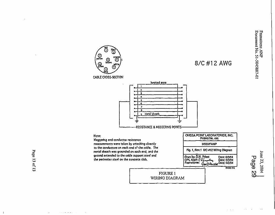
6.4 Electrical Wiring Diagrams
6.4.1 The external connections to the test cable shall conform to the Electrical Wiring Diagrams
provided by OPL (See figure 1 in this test plan). All changes to the diagram shall be
implemented and controlled by FANP and approved by MSSI. Final revisions of the
diagram shall be implemented and controlled by FANP. Final revisions of all diagrams
shall be provided by FANP in this Test Plan for inclusion into and use in preparing the
final test report.
6.5 Test Configurations
6.5.1 General
6.5.1.1 The test specimen shall be sufficiently secured to the test deck andlor sealed by
Laboratory personnel, in accordance with Instructions and drawings. The test deck will
consist of a concrete slab, reinforced with structural steel elements sufficient to carry
the load of the test specimen and support assembly.
6.5.1.2 The concrete test slab is to be cured and conditioned to reduce the risk of spalling.Where an existing test slab is to be reused, it shall be inspected to ensure that it is in
good condition. The slab will be conditioned to moisture equilibrium at indoor conditions
or drier to ensure no spalling.
6.5.1.3 Penetration openings for the Meggitt cable will be sealed using ceramic fiber.
6.5.2 Test Specimen
All test items will be constructed in accordance with drawings provided by FANP, and inaccordance with MSSI Document ER 04-033, Unpacking. Inspection, Installation andStandard Practice for Fire Rated Cable. Tools used for test cable bending shall be
Page 7 of 13

Framatome ANP June 23, 2004Document No. 51-5045887-01 Page 24
approved by MSSI and identified by tool manufacturer and model number on the OPL
QC documentation for the installation of the test items.
6.5.3 Grounding of SupportsMeggitt Cable supports will be grounded by attaching grounding cables to the through
slab all thread rod located on top of the slab. This all thread rod attaches the surface
mounted steel plates for each of the hangers to the slab.
6.6 Thormocouple Installation
6.6.1 Furnace thermocouples shall be provided and installed in accordance with US NRC GL
86-10, Supplement 1. All thermocouples used in this test program shall be provided andinstalled by OPL, with QC surveillance by Laboratory personnel.
6.6.2 The measured temperature to be compared with the standard time-temperature curve Is
to be the average temperature obtained from the reading of thermocouples symmetrically
disposed and distributed to indicate the temperature near all parts of the specimen.
6.6.3 At least three thermocouples are to be used with no fewer than five thermocouples per
100 square feet of floor area. The junctions of the thermocouples are to be placed 12
inches from the exposed surface of the test assembly.
6.6.4 Each furnace thermocouple is to be enclosed in a sealed protection tube. The exposed
combined length of protection tube and thermocouple in the furnace chamber Is to be not
less than 12 Inches.
6.6.5 The time constant of the protected thermocouple assembly is to be within the range of
5.0 to 7.2 minutes. A typical thermocouple assembly complying with this time constant
requirement Is fabricated by fusion-welding the twisted ends of No. 18 AWG chromel-
alumel wires, mounting the leads in porcelain insulators and inserting the assembly into astandard weight Yt inch (0.84 inch outside diameter) black wrought iron, black wrought
steel or Inconel pipe, and sealing the end of the pipe that is inside the furnace. The
thermocouple junction is to be inside the pipe, 1/2 inch from the sealed end.
6.6.6 The temperatures are to be read at Intervals not exceeding 1 minute throughout the fire
test.
6.6.7 The temperature of the furnace is to be controlled so that the area under the measured
time-temperature curve, obtained by averaging the results from the thermocouple
readings, Is within 10 percent of the corresponding area under the standard time-
temperature curve for a 1 hour test.
6.6.8 Engineering thermocouples for information only will be provided for temperature
measurements of the cable sheath outside the fire test chamber. One thermocouple will
Page 8 of 13

Framatome ANP June 23, 20044Document No. 51-5045887-01 Page 2
be placed on the each cable sheath as near to the cable exit from the test slab as
practical, and another thermocouple will be placed on each cable sheath approximately 8
to 16 inches away from the previous measurement location on the cold side of the test
slab.
6.7 Preburn Inspection
6.7.1 Prior to the commencement of the fire endurance test, a thorough check of the test
assembly and associated equipment (including data recording equipment, megohmeter
for Megger testing, and conductor resistance testing equipment) and completion of
applicable Laboratory QANQC checklists shall be performed and documented by the
testing laboratory.
6.7.2 Written approval of the construction, assembly, installation and instrumentation will be
supplied by FANP and OPL prior to performance of the fire exposure test (a sign-off
sheet for this purpose will be supplied by the Laboratory).
7.0 PROCEDURE
7.1 General
7.1.1 The testing sequence will be as follows:
7.1.1.1 After construction and connection of the test assembly and prior to the start of the fire
endurance test: Megger testing data collection shall be conducted in accordance withSection 7.2. Conductor resistance data collection shall be performed in accordance
with Section 7.3.
7.1.1.2 During the 1-hour fire endurance test, Megger testing data collection shall be performed
starting at 20 minutes into the fire test and will be conducted at 20 minute Intervals
during the test. The test may be extended past 1-hour as necessary to finalize thetesting. Megger testing data collection shall be conducted in accordance with Section7.2..
7.1.1.3 At the completion of the fire endurance test the test assembly shall be subjected to a
hose stream test in accordance with Section 7.4.
7.1.1.4 After the hose stream test, the following monitoring/data collection shall be performed:
Megger testing data collection shall be conducted in accordance with Section 7.2.
Conductor resistance data collection shall be performed in accordance with Section 7.3.7.2 Megger Testing Data Collection
7.2.1 Megger testing data collection is to be conducted before and during the fire test andagain after the hose stream test. The first Megger testing data collection is to be
Page 9 of 13

Framatome ANP June 23, 2004Document No. 51-5045887-01 Page 26
conducted after the installation of the cable into the test structure and prior to
commencement of the fire endurance test. Starting at 20 minutes into the fire test.
Megger testing will be conducted and repeated at 20 minute intervals during the test, with
the last set of readings obtained starting at 60 minutes into the fire test. The test duration
may be extended as necessary to complete the testing. The final Megger testing data
collection is to be conducted following the hose stream test.
7.2.2 The Megger testing is to be performed with a megohmeter. The 8-conductor, #12 AWG
cable shall be tested at 500 VDC.
7.2.3 The Megger testing is to be performed on each adjacent conductor-to-conductor path and
on each conductor-to-cable sheath path.
7.2.4 The Megger testing data collection results shall be corrected to reflect only that portion of
insulation resistance which is contributed to by the Meggitt cable.
7.2.5 The results from each of the Megger testing data collections along with a detailed
explanation of the data correction and the final corrected results shall be documented in
the final test report.
7.3 Conductor Resistance Data Collection
7.3.1 Conductor resistance data collection will occur prior to the start of the Fire Endurance
and after the hose stream test. Conductor resistance shall be measured for each
conductor in each cable. Conductor resistance will be measured utilizing an Ohmmeter.
7.3.2 The results from each conductor resistance data collection shall be documented in the
final test report.
7.4 Water Hose Stream Test
7.4.1 Immediately following the fire endurance test, a hose stream test will be performed in
accordance with USNRC Generic Letter 86-10, Supplement 1. Enclosure 1, Section VI.
The hose stream will be 'applied at random to all exposed surfaces of the test specimen
through a 1-112" fog nozzle set at a discharge angle of 30 degrees with a nozzle pressure
of not less than 75 psi and a minimum discharge flow of 75 gpm with the tip of the nozzle
at a maximum of 5 feet from the test specimen. Duration of the hose stream application is
5 minutes." Proper safety precautions shall be exercised. Only those personnel required
to perform the hose stream test shall be allowed in the immediate area, and only then
with appropriate breathing apparatus. Prior to the hose stream application, the laboratory
will ensure the correct angle spray pattern, pressure and flow is being achieved through
calibrated gauges and other equipment as required. This is to be documented by OPL.
Page IOof13
Framatome ANP June 23, 2004Document No. 51-5045887-01 Page 27
CAUTION: THE TERMINATIONS AND CABLE TEST LEADSEXTERNAL TO THE FIRE CHAMBER SHALL BE PROTECTED FROMTHE WATER SPRAY DURING THE HOSE TEST
7.5 Fire Endurance Test
7.5.1 The test equipment and test assembly are to be protected from any condition of wind or
weather that influences the test results. The air temperature at the beginning of the test Is
to be within the range of 50 to 901F, unless otherwise approved by MSSI.
7.5.2 The test item shall be exposed to the standard time/temperature curve found in ASTM E-
119 (88) for a minimum period of sixty (60) minutes, unless directed by FANP to conclude
the test.
7.5.3 Furnace pressure shall be controlled to be as nearly neutral as possible with respect to
the surrounding laboratory atmosphere, measured at the vertical mid-point of the test
specimen.
7.5.4 The testing organization shall adapt their testing procedures to assure the fire test
complies with the requirements established by the referenced portions of the referenced
standards. Any changes, revisions, or deviations required to comply with this
requirement shall be documented and properly justified and included as part of the final
test report.7.6 Furnace Thermocouple monitoring
7.6.1 During the fire exposure period, the thermocouples will be scanned at one minute
intervals or less. Data storage for reporting purposes will be at one minute intervals,
although the furnace thermocouples will be scanned and displayed every 15 seconds, to
allow close control of the furnace. The test report will contain thermocouple data at one
minute intervals.
7.6.2 Monitoring of all thermocouples will be terminated upon completion of the fire endurance
test.
8.0 FIRE TEST REPORT
8.1 The Laboratory will submit a report on the results of the test including whether the
acceptance criteria for fire test were met. Initially, a DRAFT report will be sent within 14
days of test completion for one set of consolidated review comments by MSSUFANP.8.2 The Laboratory will assemble the final test report, containing the collected data and
required quality control documentation. Five (5) hard copy sets of the final report along with
(5) CD's of test reports and 5 copies of the VHS video of the test will be provided to FANP.The CD's will contain the test report in pdf format, all test data in Excel® format and all
Page 11 of 13

Framatome ANP June 23, 2004Document No. 51-5045887-01 Page 21
photographs (whether or not they were selected for use in the final report) In high
resolution jpeg format.8.3 The test report shall be prepared in sufficient detail to summarize the total testing activity.
The report shall include as a minimum:
a) Identification of the testing laboratory and identification of the employer of thepersonnel who witnessed the preparation of the test samples.
b) A description of the assembly, materials and installation of the fire resistive cableIncluding drawings depicting the geometry and location of the fire resistive cablewithin the test assembly.
c) The type of fire resistive cable including description and manufacturers partnumber.
d) Complete description of the electrical circuit.e) A record of the test instruments used and calibration verification.f) The temperature of the furnace during the fire test.g) A description of the equipment used for the hose stream test.h) A record of the hose stream test.i) A record of the Megger test measurements and the elapsed time between the end
of the hose stream test and the beginning of the Megger test.j) Observations on the behavior of the cable during the fire endurance test and during
the hose stream test.k) Observations on the behavior of the supports during the fire endurance test and
during the hose stream test.I) A record of the conductor resistance data collected.
Page 12 of 13
00-~
0
CC,9
r i
X(00 0
o0AVCOZ
co
8/C #12 AWG
CABLE CROSS-SECTlON
heated areaI7 I II ;
i I 4t
0- I 6,0- I 9 .is- 7
Ilq metal sheath jI
I I
Note:Meggering and conductor resistancemeasurements were taken by attaching directlyto the conductors on each end of the cable. Themetal sheath was grounded on each end, and theground extended to the cable support steel endthe perimeter steel on the concrete sleb.
OMEGA POVIT LABORATORIES, INC.Ploject NO. xxc
MSSVFANP
Flo.1, Rev.1 8C *12Wiring Digm
Dwn by. b.N. iiest Date: 6W3r4OPL Appt:e0 ._,4.. Date: 6304Franatome: Date: 613'a4
W
0
W
f-
P)M
C2
(Do(0FIGURE I
WIRING DIAGRAM
ac,.: r"

81W X 13L X 1' THKSTEEL PLATE (A36)
8*W X 8L X 1 THKSTEEL PLATE (A36)
6' RADIUS TYP.DN 2'-9'
-48'
49q' -
X-TO BE LOCATED AT THE CENTER OF SUPPORTS ±2'
HSSI FIRE RESISTIVE CABLE TESTPLAN VIEW ABOVE AND BELOW TEST SLAB
- ---- - --- -- P.-
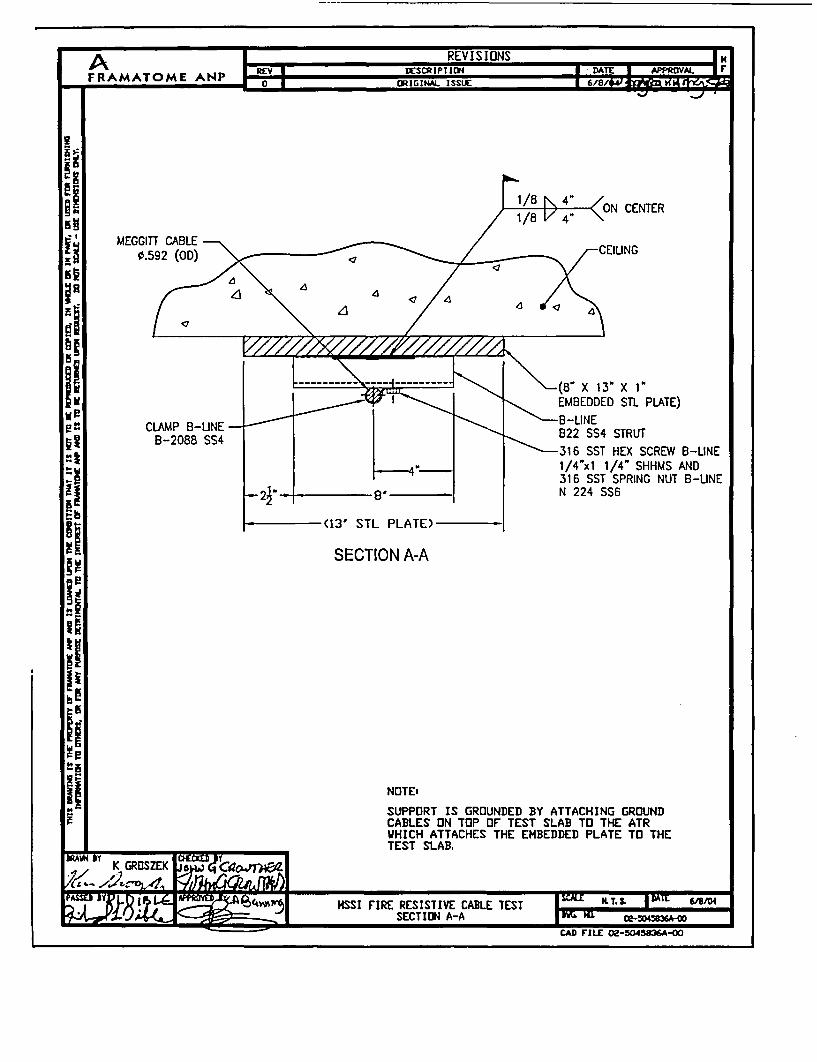
CENTER
MEGGITT CABLE0.592 (OD)
-(85 X 13 X 1EMBEDDED STL PLATE)
-316 SST HEX SCREW B-LINE1/4"xl 1/4" SHHMS AND316 SST SPRING NUT B-LINEN 224 SS6
SECTION A-A
NOTEi
SUPPORT IS GROUNDED BY ATTACHING GROUNDCABLES ON TOP OF TEST SLAB TO THE ATRWHICH ATTACHES THE EMBEDDED PLATE TO THETEST SLAB.
CAD FILE 02-5045836A-o
A A I E I S FFRAMATOME ANP*m RGMLIS / =
-i
laEl
I!iiii
xii.I-
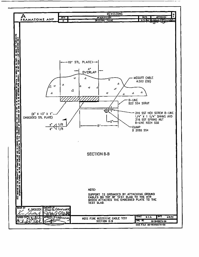
(8" X 13" X 1'.EMBEDDED STL PLATE)
316 SST HEX SCREW 8-UNE1/4" X 1 1/4" SHHMS AND316 SST SPRING NUT8-LINE N224 SS6
-AMP2088 SS4
SECTION B-B
NOTEt
SUPPORT IS GROUNDED BY ATTACHING GROUNDCABLES ON TOP OF TEST SLAB TO THE ATRWHICH ATTACHES THE EMBEDDED PLATE TO THETEST SLAB.
- .
MAWN 1Y K GROSZEK ) 14A 9'cA9,jToej41�1�7 z,7, -4 RnL e-, 6zo. Mt
Asscm Lb 1 cA:eA _ HSSI FIRE RESISTIVE CABLE TEST I VA.Ls. 1I DT
SECTION B-B I 0-D45WA-M~ - ,AU I ILL - -------- 1A
L.Ka PAILL Uzu4zff;/ 7w

x B* x I'3EDDED STIL PLATE)
5S X 5- X t/2' 5TL PLATE(NOTCH EACH CORNER OF THE
PLATE %' TO 4' TO ALLOWFOR EIBED PLATE BOLTS)
CENTER
3S X S' X 3/16 THKX 42' LONG STL TUBE
i
\ \ - MEGGITT CABLE 0.592 (00)
\INC PLAIED HEX SCREW B-LINE1/4 X Q7SHH AND\ZINC PLATED SPRING Al
1NUT /4-20
2' X I 5/8' X 10 CA THK
-B-LINE 304 SST PLATE (SEE DETAL 1)822 CRN STRUT
SECTION C-C
DLIAETER HOLE
DETAIL 12' xl 5/8' xtO CA THICK304 SST PLATES NOTE,
1. SUPPORT IS GROUNDED BY ATTACHING GROUNDCABLES ON TOP OF TEST SLAB TO THE ATRWHICH ATTACHES THE EMBEDDED PLATE TO THETEST SLAB.
2. THESE TWO EDGES SHOULD BE CHAMFERED ORROUNDED TO PROTECT AGAINST KNICKS TO CABLESHEATH.
HSSI FIRE RESISTIVE CABLE TESTSECTION C-C

REVISIONS I N
FRAMATOME ANP o 1 rup-
GENERAL NOTES
1. Meggitt Si 2400 Cable Installation:
a) Cable must be uncoiled as the cable is fed out along the routing path. Whetheron a reel or in factory coils, the cable must be unrolled in a tangential (circular)
gy manner. DO NOT UNCOIL BY PULLING ON THE END AND HELICALLYISSTRETCHING.
El b) Minimum bend radius is 6 inches. At least one bend shall be installed with aminimum bend radius as indicated on Drawing No. 02-5045835A.
Z c) Each cable contains a factory installed splice located approximately 12' fromone end of the cable sample. The factory installed splice shall be located asshown on drawing 02-5045835A at approximately the midpoint between thesupports.
d) Each cable has factory installed terminations at each end of the cable. TheIterminations each have pigtails approximately 3' long.e) Repeated bending and straightening of the cable should be avoided.f) Any smooth surface or appropriate radius may be used to form the cable. EMT
tube benders are suitable. In many cases the cable can be hand formed.g) Smooth contour changes such as dents, digs, ripples, or wrinkles are acceptable.h) Gouges or cuts in the cable sheath which exceed 10% of cable wall thickness
may be cause for rejection. Wall thickness is nominally .015".i) Outside diameter for the Meggitt cable is 0.592"
t 2. Where the Meggitt cable is attached to the B-Line strut using B-Line 2088 SS4 clampand a SST plate, place the hex screw through the clamp then through the SST plateand into the spring nut. The applied torque on all hex screws for attaching the B-Line2088 SS4 clamps should be approximately 6 lbf-ft.
l 3. 1" thick plate steel shall be installed against the test slab to simulate embed plates.The plates shall be bolted to the test slab utilizing l2'" ATR extending through the testslab to ensure that the plate stays in place. ATR shall be placed at least at each of the4 corners of the plate, no closer than 1" to the edge of the plate. Additional ATR may
I ~ be utilized if necessary to ensure that the plate remains in place.
YE
1=,, K GRt3SZEK jj~H.J aiC~"sr'
/1 r'"-w, .z4ch2SkImnSSI FIRE RESISTIVE CABLE TEST I -E K T. L DAT G4
JWJOPCm GENERAL NOTES I- Nf D"0onsaa39-c_, rADe re ZL no~8J7Aog
By [;AD FILL O9-305W3°A-O

A REVISIONS IHAREVA REV I DESCRIPTION I -- D r
o 0 ORIGINAL ISSUE 6/8s/t 1
I I I INCCR13ATE AS BUILT CDIITIONIS 1 6/23/04 1
BILL OF MATERIALSUPPUED BY MEGCITT SAFETY SYSTEMS INCQUANTITY UNIT DESCRIPTION
40 LF 8C #12 AWG S12400 FIRE CABLE, PN: 300283-5
NOTE: FACTORY INSTALLED CABLE SPUCE AT APPROX 12' FROM ONE ENDAND FACTORY INSTALLED CABLE TERMINATIONS AT EACH ENDS
4 EA CLAMP 8 2088 SS43 EA 316 SST HEX SCREW B-UNE 1/4" X 1 1/4" SHHMS
3 EA 316 SST SPRING NUT B-LINE N224 SS6
1 EA 2" X 1 5/8" X 10 GA THK 304 SST PLATE3 LF C-UNE 822 SS4 STRUT1 LF B-UNE 822 DURA GREEN STRUT 822 GRN
1 EA S-UINE ZINC ELECTROPLATED SPRING NUT 1/4-20 N224ZN
I EA S-LINE ZINC ELECTROPLATED HEX SCREW 1/4'x OSHHMS
A,SUPPUIED BY OMEG A POINT LABO0RATORI ES
OUANTITY UNIT DESCRIPTION
4 IF 3" X 3" X 3/16 THK STEEL TUBING, ASTM AS00 GR B5 IF 8' X 1" THK STEEL PLATE A36
1 EA 5" X 5- X 1/2" THK STEEL PLATE A361 EA CONCRETE SLAB 96"X156'
AR PENETRATION SEAL MATERIAL (CERAMIC FIBER)
20 LF 1/2- ATR
32 EA 1/2" STEEL WASHER32 EA 11/2" A-307 STEEL NUT
P(AWN ATV.�, K GROSZEK 4
Wsma JTJ2 I 19L.C-- BY 8A KTL I DAILnni KSSI FIRE RESISTIVE CABLE TEST 6/8/04
BILL BF MATERIALS W E 02-30mi"ICAD FILE 02-5043841A-00

, 7 _REVISIONS UNA REV I DESCRIPTIO U DA I
F RAMATOME A 0 Po ORIGINAL ISSLI 6/8/
S.f
la
I adiR*9I
TEST ARTICLE ATTRIBUTE CHECKLIST
PROJECT NUMBER:
PROJECT TITLE: MEGGITT FIRE RESISTIVE CABLE TESTING
ATTRIBUTE SAT UNSAT1 TEST DECK
A Test deck configuration and dimensions per approved drawings_ B Condition of test deckC Test deck conditioned to moisture equilibrium at indoor conditions
11 SUPPORTS/STEEL PLATESA. Correct materials used D _
B. Installed per approved drawingsC. Spacing between the two Section A-A supports is equal to or
greater than shown on approved drawings .D. Supports for Meggitt cable are properly grounded
_ E. Applied torque values for strut clamps per approved drawingsF. Welds per approved drawings
Ill MEGGITT CABLEA. Cable installed per approved drawingsB. Minimum bend radius installed where shown on approved
drawingsC. Factory installed splices installed as shown on approved drawingsD. Factory installed terminations provided at each end of cableE. No gouges or cuts in the cable sheath which exceed 10% of cable
wall thicknessV TEST EQUIPMENT
___ A. Wiring of test articles conform to the Figure I in the Test Plan _
B. All electrical devices and equipment have been tested prior to thestart of the test to ensure that they are properly connected andfunctioning as required, showing proper readings on dataacquisition equipment
C. Furnace thermocouples are the correct type and are installed perthe Test Plan
NOTE: Verification to be made using initials of OPL Quality Assurance Personnel
WAM MT K GRDSZV IS I/I','" 1 '7n4;,(7qZoJfflPDLT) 404 2 HSSI FIRE RESISTIVE CABLE TEST I t. I DA.a - ) I TEST ARTICLE ATTRIBUTE CHECKLIST WI i 4 ot4n< u0/4e
CAD MIE 02-5045842A-O0

- -
Report No. 14980-119368, Rev.1AREVA
FINAL REPORTAugust 11, 2004
APPENDICES Page 37
Appendix B
MEGGERING AND CONDUCTOR RESISTANCE RESULTS

Page 38MEGGERING DATA SHEET
Client: AREVA Date: 1A-&44Project No: 14980-119368
Test Condition: (ee During Test Post Hose Stream Post Test Cold (circle one)
Meoaer Onernt.r:\ LL pi. U 0 Scribe-'c"- -r - -
Megger ID: 1 AC) Calibration Due:, as n ^ ,
8/C #12 - CABLE #2
FROM TO RESISTANCECOND. # COLOR COND. # COLOR (Megohms) TIME
I Red 2 Black IbK+ -: 5 aI Red 3 Orange }lbk-)-
I Red 4 White lKI Red 5 Blue . I'9 t51 Red 6 Green ID<+1 Red 7 Yellow -_1_ __K_ _ _
1 Red 8 Brown jIK+ . S4I Red Shield _____+ _s_
2 Black 3 Orange IDKt2 Black 4 White Ib 1K+2 Black 5 Blue AMK± 1: j+I -2 Black 6 Green I _ _ K_2 Black 7 Yellow2 Black 8 Brown AR'.2 Black Shield atK+3 Orange 4 White 1ft3 Orange 5 Blue l 03 Orange 6 Green _bKt
3 Orange 7 Yellow3 Orange 8 Brown I _ _ _ _
3 Orange Shield 1_K_4 White 5 Blue IbK+4 White 6 Green bK-)-4 White 7 Yellow 10K)-4 White 8 Brown 1OK+4 White Shield 1DKt A)35 Blue 6 Green L5 Blue 7 Yellow lath5 Blue 8 Brown _ _ _ _ _ _
5 Blue Shield _____Ir A:03
Th.- 7p)___ -pa-CC'�,c )4 A- t

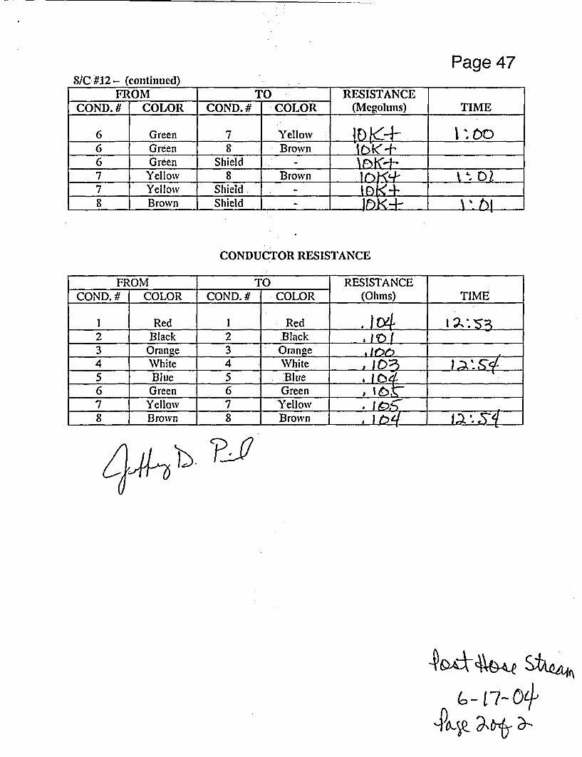
Page 398/C #12 - (continued)
FROM TO RESISTANCECOND. # COLOR COND. # COLOR (Mlegohms) TIME
6 Green 7 Yellow 1_DK_ + A_.___6 Green 8 Brown ItK+6 Green Shield IN<l7 Yellow 8 Brown 1QK+7 Yelloiv Shield I____ t8 Brown Shield - 00
CONDUCTOR RESISTANCE
FROM TO RESISTANCECOND. If COLOR COND. # COLOR (Ohms) TIME
I Red I Red ._I_ C)_______2 Black 2 Black .bc l3 Orange 3 Orange .Oc I1 /4 White 4 White 6 : .5 Blue 5 Blue6 Green 6 Green .Q.S7 Yellow 7 Yellow . 178 Brown 8 Brown . 34 '; . l7
if F
-Pa~e 9C5--~ L

. -... . . . . . .
Page 40MEGGERING DATA SHEET
Date: ;?- I IClient:Project No:
AREVA14980-119368
Test Condition: During Test . Post Hose Stream Post Test Cold (circle one)
Meeeer Onerator: J el&.m- PAO b D Scribe:Megger ID: 'J" U Calibration Due: I - 7 - WOE
8/C #12 - CABLE #2 £c-00 iC -b
FROM TO RESISTANCECOND. II COLOR COND. # COLOR (Mcgohms) TIME
I Red 2 Black 41 Red 3 Orange ro K-1 Red 4 White 16 K+ 9 ! 491 Red 5 Blue lO _ _+
I Red 6 Green _0O KI Red 7 Yellow it) K_1 Red 8 Brown 2K fI.I Red Shield r j)K q 44-2 Black 3 Orange ih KJ2 Black 4 White tnK+2 Black 5 Blue '__ _ l _ __
2 Black 6 Green IC) K t2 Black 7 Yellow It) KJ_ _
2 Black 8 Brown t _ _ _ _ _
2 Black Shield O3 Orange 4 White 3J43 Oranoe 5 Blue tK tc . q3 Oradge 6 Green E nK_+3 Orange 7 Yellow I _ __k___
3 Orange 8 Brown I O g
3 Orange Shield /04 White 5 . Blue J b .4 White 6 Green 4ng4 White 7 Yellow4 WWhite 8 Brown4 White Shield *5 Blue 6 Green . ._ _ _5
5 Blue 7 Yellow _ _ _ _ _
5 Blue 8 Brown . .5 Blue Shield I 1Ok
�2'�$�� 4* Jj2 P65 / e a

Page 41SIC #12 - (continued)
FROM TO RESISTANCECOND. I COLOR COND. # COLOR (Mcgolims) TIME
6 Green 7 Yellow )tX 4 9 S6 Green 8 Brown J1K_ _
6 Green Shield .l __ <+7 Yellow 8 Brown _ _K7 Yellow Shield : l O t_8 Brown Shield .19l
CONDUCTOR RESISTANCE
FROM TO RESISTANCECOND. # COLOR COND. # COLOR (Olhms) TIME
I Red I Red jqQ4|2 Black 2 Black ._O____3 Orange 3 Ornge 34 White 4 White q S5 Blue 5 Blue OQG6 Green 6 Green q(7 Yellow 7 Yellow q 78 Brown 8 Brown .
'b
b-l7?-o4

Page 42MEGGERING DATA SHEET
Client: AREVA Date:Project No: 14980-119368
Test Condition: Pre Test rinPot. Hose Stream Post Test Cold (circle one)
Megger Operator: f 4 Scribe: m5EMZMegger MD: - -I Calibrtion Due: - 7 -
8/C #12 - CABLE #2
FROM TO RESISTANCECOND. # COLOR COND. # COLOR (Megohms) TIME
I Red 2 Black t/1 141I Red 3 Orange 4.5 1 1:1 71 Red 4 White I *g<I Red 5 Blue1 Red 6 GreenI Red 7 Yellow1 Red 8 BrownI Red Shield - ' _l l2 Black 3 Orange i1: B
2 Black 4 White _ _______
2 Black 5 Blue V_,___2 Black 6 Green _32_2 Black 7 Yellow . ZJ1'.2 Black 8 Brown2 Black. Shield .3 Orange 4 -VWhite3 Orange 5 Blue ..3 Orange 6 -Green3 Orange 7 Yellow3 Orange 8 Brown3 Orange Shield - c l4 White 5 Blue * Jj1',4 White .6 Green ______ _
4 White 7 Yellow r
4 White 8 Brown4 White Shield -5
5 Blue 6 Green .5 Blue 7 Yellow I *_ __ __.
5 Blue 8 Brown _ _*_ ___
5 Blue Shield 1 . 1.JJ4
L 44) �b, P,2,pASy, I X

Page 438/C #12 - (continued)
FROM TO RESISTANCECOND. # COLOR COND. # COLOR (Megohms) TIME
6 Green 7 Yellow |6 Green 8 Brown I t'. 4hA6 Green Shield a7 Yellow 8 .Brown *9 I 4-7 Yellow Shield -
8 Brown Shield I
CONDUCTOR RESISTANCE
FROM TO RESISTANCECOND. # COLOR COND. # COLOR (Ohms) TIME
1 Red 1 Red2 Black 2 Black3 Orange 3 Orange _
4 White 4 White5 Blue 5 Blue _ _
6 Green 6 Green7 Yellow 7 Yellow8 Brown 8 Brown
44�L -P,- 0
3VNU"U 'buA~P-)eld-

Client:Project No:
Test Condition:
Megger OperatoMegger ID:
Page 44MEGGERING DATA SHEET
AREVA Date: 4,47-!6y14980-119368
Pre Test During Test Post Hose Stream Post Test Cold (circle one)
~r_ _1 .D . _r.i_,. . _I -rAn
Calibration Due: 1
8/C #12 - CABLE #2
FROM TO RESISTANCECOND. # COLOR COND. # COLOR (Megohms) TIME
I Red 2 Black i.4 .L *.I Red 3 Orange JI Red 4 White \ ._X_ _
I Red 5 Blue _ *_ __ __3
1 Red 6 Green 1_4_ _
I Red 7 Yellow 1 ._ 4 _ _
1 Red 8 Brown 1_ _ _ _ _
I Red Shield 1 ..2 Black 3 Orange -
2 Black 4 White .2 Black 5 .,Blue _ _ _ _
2 Black 6 Green . ._ _ _ _
2 Black 7 Yellow ._ _ _
2 Black 8 Brown I .0 _
2 Black Shield .I3 Orange 4 White .! 1q3 Orange 5 Blue _ _.___Sk
3 Orange 6 Green _ ._ _ _ _
3 Orange 7 Yellow I, __
3 Orange 8 Brown l_1__E3 Orange Shield4 White 5 Blue. 1.4 White 6 Green 1 ._ _
4 White 7 Yellow _ __a
4 White 8 Brown A ;2*j.4 White Shield ._.l_______5 Blue 6 Green l . l .. I a;La.5 Blue 7 Yellow 1 _ I _ _ _
5 Blue 8 Brown I_._ ___
5 Blue Shield I__ _ 17 X : >1
_t��t 16'p,

qLf 9O-(q0/&,)
Page 45S/C #12 - (continued)
FROM TO RESISTANCECOND. # COLOR COND. # COLOR (Mcgohms) TIME
6 Green 7 Yellow , lS6 Green 8 Brown 1
6 Green Shield -
7 Yellow 8 Brown7 Yellow Shield I
8 Brown Shield I . j _
CONDUCTOR RESISTANCE
FROM TO RESISTANCECOND. # COLOR COND. # COLOR (Ohms) TIME
I Red I Red2 A Black 2 Black3 Orange 3 Orange4 White 4 White5 Blue 5 Blue6 Green 6 Green7 Yellow 7 Yellow8 Brown 8 Brown
b,./ C9 %:)
A- 17 -0f

Page 46MEGGERING DATA SHEET
Date: L -C9-Client:Project No:
AREVA14980-119368
Test Condition: Pre Test During Test Post Test Cold (circle one)
Megger ODerator: J P; o Scribe: 0,Megoer ID:
'4
Calibration Due: t )- °s~
8/C #12 - CABLE #2
FROM TO RESISTANCECOND. # COLOR COND. # COLOR (Mcgollms) TIME
1 Red 2 Black M S1 Red 3 OrangeI Red 4 White 1_ __ __
I Red 5 BlueI Red 6 Green 1_ nKI Red 7 Yellow |____I Red 8 Brown 1____I Red Shield - t__2 Black 3 Orange Ih_4_2 Black 4 WVhite Inv2 Black 5 Blue iK_2 Black 6 Green 1 n[ J.52 Black 7 Yellow ____ __
2 Black 8 Brown 1 _ ___
2 Black Shield -
3 Orange 4 White I____3 Orange 5 Blue _ ___
3 Orange 6 Green -. _ ____
3 Orange 7 Yellow3 Orange 8 Brown3 Oranne Shield 104 White 5 Blue tle_4 White 6 Green I1bK+4 White 7 Yellow 1f<4 White 8 Brown I n K4 White Shield l 1 '
5 Blue 6 Green A ',5 Blue 7 Yellow I r rno)5 Blue 8 Brown Ile___5 Blue Shield - . , 0
k4l N 'U,I{TC76e C
Page 47S/C,#12 - (continued) . .
FROM ._ TO RESISTANCECOND. # COLOR COND. # COLOR (Mcgohms) TIME
6 Green 7 Yellow - .6 Green 8 Brown l bK _
6 Green Shield .7 Yellow 8 Brown7 Yellow Shield. -
8 Brown Shield - -
CONDUCTOR RESISTANCE
FROM | _ TO RESISTANCECOND. # COLOR COND. # COLOR (Ohms) TIME
1 Red 1 Red . |5R32 Black 2 Black j3 Orange 3 Orange . If,4 White 4 White ) 1; .,5 Blue 5 Blue ,6 Green 6 Green . 1t7 Yellow 7 Yellow . Z
8 Brown 8 Brown .b4,
'D IP P
&- 17- 0+

"MEGGITT
IhLE .58391R-1
oA: I
05-12-04
MEGGITT SAFETYSYSTEMS INC
Page4A$F2ACCEPTANCE TEST I)ATA Si ET
* }Fo-t
FIRE1 CABLE' ASSE1AMBLY
PART NUMBER: 5V0283 5E040zSJ
TEST 1RO(G;RAiM NUMBEH: 5181
SERIAL NUMBER:
REVISON C(
1.0 Dielectric Strength at room temperature per STP 2191. Revision C
I1 3200 YDC tietween conductor and slicaitd for 60 seconds. No inclicatiof bre Cia A1 ). 2- (!apil
Tech Stamp/Date
1.2 3200 VDC conductor to conductor for 60 seconds. No indication of brndownjUN 0 4 200
(FfailTech Stamp/Date
2.0 Insulation Resistance at room temperature per STP 2190, Revision C(All unused pins connected to sheath. Record values.)
,.1 1 x 10 ollills 7 (.0 .x 10 ohms
2 1-0 x 10 ohlmlts 8 1.0 x 10 ohnms
3 1.0 x 10¹² olms 9 t/A x 10 ohims
4 1.0 x 10 ohnms 10 M /A x 10 ohlms
5 1.0 x 10 ollms 11/A x 10 ohnils
6 1.0 x 10 olims 12 W /A x 1o ohms
4,A JUN 0 4 20m-eiech Stamnp/Date

.....................................................
1 MEGGITT
JllE 5839IR-1
PAGE1 2 OF 2
MEGGITT SAFETYSYSTEMS INC
PART NUMBER: ________ JSERIIAl NUMBER: 002
3.0
3.1
3.2
I)C Continuity peer STP 2207, Revision - . (Limiit: Refer to cable drawlinig.)
Cable Length: feet
Coiidtictor Resistance:
1 J.. olltis S , .1 0111115 9 0111)mS
.2 0- A-1.. ohs 6 0._ o ms 10 N A oh1s
3 0.1_ olhlils 7 A I ohms II MI o 0hm11s
4 0.| o s 8 0..1.1ohms 12 - /A ohls
Fl~ail OS CJUN 04 20Tech Stamfl/Dite
4.0 Test Equipiment list
Nomenclature
Iligh Resistance BIridge
1-1i-Tot
Digital Mullinieter
Manufacturer& Model No.
6R IG4+ A
AR 5205 A:
FL-LKa '7
Identification No.
^ 14672
A 1466o
1, 1 1
CalibrationDue Date
6- 2- 05
7- ig-o5
2- i0-05
I . .ay 6 Yu
DATE: _t________MSSI QA REVIEW:

C"MEGGNTTMEGGITT SAFETYSYSTEMS INC1915 VOYAGER AVE. SUNIM VALLEY, CA. 93063805.584-4100 FAX 805-584-9157
Packing Slip
Invoice To:Ship To:
OMEGA POINT LABORATORIESATTN: CONSTANCE TIUMPITREY210-635-812016015 SHADY FALLS ROADELMENDORF TX 78112
Plickslip 81945
Page I
Datc 601M
Cus.tomer No. 69444
Orter Ntunber 260500-005 SO
ltelated 1'.0.
Brn/PIt 200
I INSP I Priority
I DT I E I.. .. . ... . .... .. . .-
IN-HIOUSE M/1EGGITT SAFETY SYSTEMS1915 VOYAGER AVENUE.SIMI VALLEY CA 93063
.: . .. . ..
Ord Date Promised Customer P.O. F .0.1D. Contract Administrator10/15/03 11/15/03 Fred Rudek Destination DIANA COX, EXT 8127
Line Item Number LocationLot Description Shipped Tag Avail. IUM Due Date Schcdule BIN IIUUSI SALES ORDER 'U l'RUVIDk' I11Z1 (.CAHL P PK'LLURAJURY .TESTS TO BE PRESENTED TO NRCUSSI WVILL IA YE JOINT RIGHTS SHARING TIE Q 4UFICATIONTO TEST L ESULTS
TESTFA LITYWILLEE READYENDOFNOVEMB R
SPLICE RkQUIRED A TIDPOINT IAN CABLE.
31.000 300283E0O40f28J FIRE CABLE I EA 11115/03 B1ank - Sales RFGRFC,
Serial #00
(D(xi0
-V e'-CY-,_, .. Quriffty Assurance Packer Track/Airbill E
Weight:Ship Via: BEST WAY PREPAY ONLY -'�' 4a.;(

Report No. 14980-119368, Rev.1AREVA
FINAL REPORTAugust 11, 2004APPENDICES Page 51
Appendix C
TEST DATA - FURNACE INTERIOR TEMPERATURES

Page 52
Project No. 14980-119368AREVA - Meggitt Cable TestFurnace Interior Temperature
2000
1800
1600
1400
0
a)I-
1200
1000
800
600
400
200
00 30 60 90 120
Time (min)

Project No. 14980-119368 AREVATest of Meggitt Cable
Time(min)
0123456789
10111213141516171819202122232425262728293031323334353637383940414243
E119 StdAverage
(OF)
68254441627814
100010601120118012401300132813471364138113961410142414361448145914701480149014991508151715251533154115491556156315701576158315891595160116061612161716231628
FurnaceAverage
(OF)
85133305575856
100210731121116912141223125012781311134313691393141514341453146714871498150915101514152115261535154615551566157315821589159216001605161216161620162316271632
Integrationof Furnace
Average(OFamin)
041
192564
121120723042407151486271742285909786
11013122721355914873162091756518940203322174123166246012604327487289363039231855333273480936302378033931340830423534388145415469564850250051516055316254724
Integrationof E119 Std
Average(OFF min)
0466932
139818642330341244945576665877409022
1030411586128681415015514168781824219606209702238623802252182663428050295123097432436338983536036875383903990541420429354445045965474804899550510521115371255314
Error( 0/a )
0.00%-91.2%-79.4%-59.7%-35.0%-11.1%-10.9%-9.42%-7.68%-5.81%-4.11%-4.78%-5.03%-4.95%-4.64%-4.17%-4.13%-3.97%-3.71%-3.40%-3.04%-2.88%-2.67%-2.45%-2.22%-2.01%-1.95%-1.88%-1.79%-1.68%-1.56%-1.55%-1.53%-1.48%-1.42%-1.36%-1.28%-1.20%-1.10%-1.01%-0.91%-0.97%-1.03%-1.07%
FurnaceProbe
#1(OF)
84143281553838989
10871172125913431390140814351483151915501573158916071625164316571659165616521648164916541666168116881696170017111713171617281728173817401742174317441751
June 17, 2004
Page 53Furnace Furnace
Probe Probe#2 #3
(OF) (OF)
84126287538809948
10291094116412351282130113221357139314251453147614951512152715421550155015441543154515471553156415751583158915961601160516151619162516271632163516381643
84113
bad TCbad TCbad TC
99310801148121412791318133413541388142514541482150415241545156115771591160316011599160516061618163016441651165816651670167316851690169516991701170417091717

Project No. 14980-119368 AREVATest of Meggitt Cable
Time(min)
4445464748495051525354555657585960616263646566676869707172737475767778798081828384858687
E119 StdAverage
(OF)
16331638164316481652165716611666167016741678168216861690169416981701170517091712171617191722172617291732173517381742174517481751175317561759176217651768177017731776177817811783
FurnaceAverage
(OF)
16371636162916301631164116501658166816741678167916831688169416971701170217041703169916971700170417041706170817081707170517051705170617091709170717061707170617071705170317021703
Integrationof Furnace
Average(OF min)
56290578585942260983625466411465691672776887170474720827369375306769237854680173818058343885073867088834189971916029323694872965099814899788
101428103066104703106340107977109616111257112897114536116174117812119451121088122724124358125992
Integrationof E119 Std
Average(°Femin)
569155851660117617186332064921665226812369724713267292774528761297773079332809338253484135857368733888939905409224993957956669737599084
100793102501104210105919107628109336111045112754114463116171117880119589121298123006124715126424128133
Error(0/ )
-1.10%-1.12%-1.16%-1.19%-1.22%-1.24%-1.25%-1.24%-1.22%-1.19%-1.16%-1.12%-1.08%-1.04%-0.99%-0.94%-0.88%-0.83%-0.77%-0.72%-0.67%-0.63%-0.70%-0.77%-0.83%-0.89%-0.94%-1.00%-1.05%-1.10%-1.15%-1.20%-1.24%-1.29%-1.33%-1.37%-1.41%-1.45%-1.49%-1.52%-1.56%-1.60%-1.63%-1.67%
FurnaceProbe
#1(OF)
17561748172017101704171317211726173017361741175217641762176017621761176117631764176117621771177717791777177017771773176917741783178017781773176917691768176617651763176217531748
June 17, 2004
Page 54Furnace Furnace
Probe Probe#2 #3
(OF) (OF)
16461643163216311630164216491657166416711677167216741678168816931697169817001698169416891690169516931698170317001699169516911688168916971700169816961696169316941691168816871687
17211716170717101721173017411748176117641766176617671772177717841790178617851779177417751771177317751779178317771776177317691768177017721774177117681767176917701769175717491743

Project No. 14980-119368 AREVATest of Meggitt Cable
E119 StdTime Average
(min) (OF)
888990919293949596979899
100101102
178617881791179317961798180018031805180718091812181418161818
FurnaceAverage
(OF)
170517051707171017061705170317041708170416991698169917071711
Integrationof Furnace
Average(0 Femin)
127628129265130903132543134183135821137456139092140730142367144001145632147262148897150539
Integrationof E119 Std
Average(0 Fomrin)
129841131550133259134968136676138385140094141803143511145220146929148638150346152055153764
Error(0/0)
-1.70%-1.74%-1.77%-1.80%-1.82%-1.85%-1.88%-1.91%-1.94%-1.96%-1.99%-2.02%-2.05%-2.08%-2.10%
FurnaceProbe
#1(0 F)
175517541752175817571753174317461755175217401738173917431747
June 17, 2004
Page 55Furnace Furnace
Probe Probe#2 #3
(OF) (OF)
168916891690169416901688168616871689168616821680168116891693
174617431747176217511746174317411746174117331730173317431743

Project No. 14980-119368 AREVATest of Meggitt Cable
Furnace Furnace Furnace Furnace Furnace
June 17, 2004
Page 56Lab "In" Cable at
Time(min)
0123456789
10111213141516171819202122232425262728293031323334353637383940414243
Probe#4
(OF)
84124297608905
104310841115115812151257127312921323135413821409143514561478149415111524152615231522152415261531154115501559156515731579158415931598160516081614161816221627
Probe#5
(OF)
85142338649965
109811241133115111731197121712421272129913221342136313811401140014471454148614691471147914841492150015091519152715361544154715541560156715701575157815851587
Probe#6
(OF)
91bad TCbad TCbad TCbad TCbad TCbad TCbad TCbad TCbad TC
1048111511681211124612741299132113411360137713921410142414361445145614631472148214911502151215211530153515421550155715621567157115761580
Probe#7
(OF)
84136298529793973
10741120114911581176120812371263128813091330135213711391140814241440145614691485149815051518152415321550155915701580157815811587159415971601160316091612
Probe Ambient Top Surface#8 Temp. of Slab
(OF) (OF) (OF)
84147330571825970
10341066108710971115114311701194121712381257127712941312132813441359137213851399141314221433144314521465147614841494149715031509151615211527153015361540
8788888887878787878787878787878888888889898989898989898990909091919191909090909191919191
868888899297
105114122127137145153160167168177181185190188199202197199211213215221220230229216229223235234234229236235240241236

Project No. 14980-119368 AREVATest of Meggitt Cable
June 17, 2004
Page 57Lab "In" Cable atFurnace Furnace Furnace Furnace Furnace
Time(min)
4445464748495051525354555657585960616263646566676869707172737475767778798081828384858687
Probe#4
(OF)
16301630162816301630164016481658167116781680167616781684169216971701170117011698169016871687169316911696170016981697169416901686168616941698169716951696169416951689168516811681
Probe#5
(OF)
15921595158915921594160316141621163216401642164216461653166116631668166916711670166716641669167116721673167516751675167316751674167516781676167516741675167516771675167416751678
Probe#6
(OF)
15851588158815921595160416141622163316401644164516491655166316651670167216741673167116691673167516761677167916801680167816801679168016831682168116801681168116821680168116841688
Probe#7
(OF)
16181621162016241627163616451653166416701676167716821687169316951700170117051706170417031708170917091711171417151716171517171717171817211719171817181720172017211720172317271733
Probe Ambient Top Surface#8 Temp. of Slab
(OF) (OF) ('F)
15441547154415471550155815671575158515931598160116051611161616201624162716311632163016291634163616371638164116421643164216451645164716491649164816481649164916511650165316571662
9091919191919191919291929292929293939191919292929293929292929293939393939494949494939394
251246246239236235249248259265256261264260268267276272273278274272276270276272277272279276281277281277267269269262268274269266267276

Project No. 14980-119368 AREVA June 17, 2004Test of Meggitt Cable
Page 58Furnace Furnace Furnace Furnace Furnace Lab "In" Cable at
Probe Probe Probe Probe Probe Ambient Top SurfaceTime #4 #5 #6 #7 #8 Temp. of Slab
(min) (OF) (OF) (OF) (OF) (OF) (OF) (0 F)
88 1682 1678 1689 1733 1664 93 27789 1683 1680 1691 1736 1666 93 27690 1684 1683 1694 1740 1668 94 27991 1690 1682 1690 1735 1665 94 28292 1685 1679 1689 1734 1664 94 27493 1682 1679 1689 1736 1665 94 27494 1679 1679 1690 1736 1666 93 27995 1680 1680 1692 1738 1667 93 27996 1682 1683 1694 1742 1670 93 27497 1679 1679 1691 1738 1667 92 27498 1675 1676 1688 1735 1664 92 27599 1674 1676 1688 1736 1665 92 275
100 1674 1677 1688 1734 1664 93 278101 1682 1688 1698 1742 1674 93 276102 1687 1691 1702 1746 1679 93 275

Project No. 14980-119368 AREVATest of Meggitt Cable
June 17, 2004
Page 59"In" Cable12" Above
Top of Slab(OF)
"Out" CableTop Surface
of Slab(0 F)
"Out" Cable12" Above
Top of Slab(OF)
Time(min)
0123456789
10111213141516171819202122232425262728293031323334353637383940414243
868687878787878788888990909293949596979897999999
100101102102103102105105104106106106107107105106104104103103
8687899399
100108114117128133142150153163159171173177182178183191187174196195203204198214215198220208220220226226226218225210225
86868686868686878888898990919293949596979698999797
100100101102100103104102103102103105106103104101101100101
Project No. 14980-119368 AREVATest of Meggitt Cable
June 17, 2004
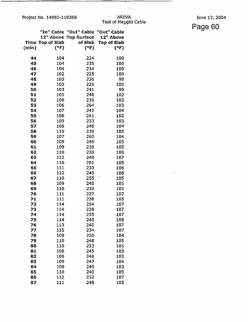
Page 60"In" Cable12" Above
Top of Slab('F)
"Out" CableTop Surface
of Slab('F)
"Out" Cable12" Above
Top of Slab('F)
Time(min)
4445464748495051525354555657585960616263646566676869707172737475767778798081828384858687
104104104102103103103105106106107106109108110107109109110112110111112110109110111111114114114114113115109110110108108109108110112111
224235234225236226241248236264242241233248239260246239239248261233240255240239237238254228255245240234250248253245248247245240252248
10010010010099
10099
102102103104102103104105104105105106107105106106105105105107105107107107108107107104105105103103104103105107105

Project No. 14980-119368 AREVATest of Meggitt Cable
June 17, 2004
Page 61"In" Cable12" Above
Top of Slab(OF)
"Out" CableTop Surface
of Slab(OF)
"Out" Cable12" Above
Top of Slab(OF)
Time(min)
888990919293949596979899
100101102
111113112111111114113116114116115113113112113
244249254253254234249258245250246254248261269
106107106106105107107109108110110110107106108

Report No. 14980-119368, Rev.1AREVA
FINAL REPORTAugust 11, 2004
APPENDICES Page 62
Appendix D
QUALITY ASSURANCE

Report No. 14980-119368, Rev.1 FINAL REPORTAugust 11, 2004AREVA APPENDICES Pae63
Quality Assurance Statement Page
Omega Point Laboratories, Inc. is an independent, wholly owned company incorporated in thestate of Texas, devoted to engineering, inspection, quality assurance and testing of buildingmaterials, products and assemblies. The company has developed and implemented a QualityAssurance Program designed to provide its clients with a planned procedure of order anddocument processing for inspection and testing services it provides to assure conformity torequirements, codes, standards and specifications. The Program is designed to meet the intent ofANSI 45.2 Quality Assurance Program Requirements for Nuclear Power Plants, and complies withthe requirements of the ASME Code, SPPE, Military Standards and other less stringent programs.It is the Laboratory's intention to adhere strictly to this Program, to assure that the services offeredto its clients remains of the highest quality and accuracy possible.
The overall responsibility of the supervision, operation and coordination of this Quality AssuranceProgram is that of the Quality Assurance Manager, a person not involved with the performance ofthe inspection or testing services, and who is under the full time employ of the Laboratory. Thisindividual is responsible for implementing and enforcing all procedures presented in the QualityAssurance Manual and the Procedures Manual. All personnel involved with activities which fallunder the scope of this Program are required to cooperate with the letter and intent of thisProgram.
All QA Surveillance documents remain on file at the Laboratory, and are available for inspectionby authorized personnel in the performance of an on-site QA Audit. All materials, services andsupplies utilized herein were obtained with appropriate QA Certifications of Compliance, and theinclusion of these in this report would not be practical nor useful to the reader.

Page 64
ACCEPTABILITY DOCUMENTATION
PROJECT NO. 14980-119368
AREVA
The following signatures attest to the review and acceptance of each attribute listedregarding the above-noted project:
I. TEST ARTICLE ASSEMBLY
Omega Point Lab
4 it, -i
&~///O
Date
II. CABLE INSTALLATION
Orpiga Point LaboratbriesA c.
Efi 9 (Z7
.at 7/0
Date
Omega Point Laboratories, Inc.16015 Shady Falls Road
Elmendorf, Texas 78112-9784 USA210-635-8100 / FAX: 210-635-8101 / 800-966-5253
www.opl.com [email protected]

ArevaProject 14980-119368 Pagep8e
11. ACCEPTANCE OF:
PRETEST MEGGERING RESULTSPRETEST CONDUCTOR RESISTANCE MEASUREMENT
Omega'Point Laboratori6s, Inc. °
EfVA J
V//0 SDate
Date
IV. FINAL PRE-BURN INSPECTION
_t,4vcW6;mra Point Laboratorievs, InI6
0 l eZ?d#7/of/_
Date"
6/,Q AzDate

Page 66
EVENT LOGFire Resistance Test of Horizontal
Concrete Slab Supporting aMeggitt Safety System Cable
PROJECT NUMBER:
14980-119368
AREVA

EVENT LOG Page 67
AREVAClient # 14980
NOTE:This Log is used to document the date and note the significant events during the completion of test project #119368for AREVA. The following is a brief description of this project:
Project No. 119368 Fire Resistance Test of Horizontal Concrete Slab Supporting a Fire-RatedElectrical Cable
Page I of 3ITEM DATE INIT'L
41 A /A,(,eage r e r- IO/ -Z�
alcoholAJ
6;?/4
-?oe-
10
ce74/ Bell
C:9
d/dW&
IVA-, a
4 4 ZL(4 - e-9-4 10 L

EVENT LOG Page 68
AREVAClient # 14980
NOTE:This Log is used to document the date and note the significant events during the completion of test project #119368for AREVA. The following is a brief description of this project:
Project No. 119368 Fire Resistance Test of Horizontal Concrete Slab Supporting a Fire-RatedElectrical Cable
Paae of 3_ITEM DATE I~- ITflT
/- E
U w)1x I;_ _ _ _ _ _ _ _
C77
4EWWIJ0t
-
LIV

EVENT LOG Page 69
AREVAClient # 14980
NOTE:This Log is used to document the date and note the significant events during the completion of test project #119368for AREVA. The following is a brief description of this project:
Project No. 119368 Fire Resistance Test of Hortzontal Concrete Slab Supporting a Fire-RatedElectrical Cable
Pa e 3 of _ITEM DATE I
te4d 627
,fear
,-4�xt &4<4r
�O P L.4c
to] I J1 -AAA
bA,(2-
014-M
I

A I REVISIONS PR ne _7FRA ATOME AP IREY I DUCRIPTION I DATE L tF1r A A Mml O -E AORIGII AL. ISSUE I 6/8/04 | ::
TEST ARTICLE ATTRIBUTE CHECKLIST
PROJECT NUMBER:
PROJECT TITLE: MFGGITT FIRE RESISTIVE CABLE TEST'INGv
ATTRIBUTE SAT |NSATI TEST DECK.
A Test deck configuration and dimensions per approved drawings .B Condition of test deck ._ _
C Test deck conditioned to moisture equilibrium at indoor conditionsSUPPORTS/STEEL PLATESA. Correct materials usedB. Installed per approved drawings VI"C. Spacing between the two Section A-A supports is equal to or
greater than shown on approved drawingsD. Supports for Meggitt cable are properly grounded a /-F. Applied torque values for strut clamps per approved drawings -_
F. Welds per approved drawings.Ill MEGGITT CABLE
A. Cable installed per approved drawingsB. Minimum bend radius installed where shown on approved
drawingsC. Factory installed splices installed as shown on approved drawingsD. Factory installed terminations provided at each end of cable zE. No gouges or cuts in the cable sheath which exceed IO% of cable
wall thicknessV TEST EQUIPMENT
A. Wiring of test articles conform to the Figure I in the Test Plan _
B. All electrical devices and equipment have been tested prior to thestart of the test to ensure that they are properly connected andfunctioning as required, showing proper readings on dataacquisition equipment
C. Furnace thermocouples are the correct type and are installed perthe Test Plan ._._A/
NOTE: Verification to be made using initials of OPL Quality Assurance Personnel
d&/PL=4- a ,Z9t/tc ItIi,1 K GR03SZq o§iMobXo'/.,S'; t - mP~APIIE9 SIR FI)IL- si RE RESISTIVE CABLE TEST KM.; IlI . /
X.JEST ARTICLE ATTRIBUTE CHECKLIST F M OW44A-
CAD FILE G2-W04M84UA

0/A RECEIVING REPORT
CLIENT/PROJECT NAM EF F
CLIENT/PROJECT NUMBER DPL DRECEIVED FROM IOAAC DPRO.IECT LOCATION Omrns Point Labs II
REPORT NUMBER ;) 3D - DkLATE RECEIVED 1-L) -.ATE INSPECTED I -It L-...RIPECTEBY Ry.I I[ UNIT C M I ACCEPTANCE j
ITEM DESCRIPTION P.O. NO. 1.0 NO. 1 MATL 1 w re EXCEfnOU ACCPTIOAN REMARKSOrdere R no~fl~fl _. ._ .'4 ACCeor n I-o _ _IT
_ rpr _ ec _ _ I Acod Hol _ .Ip
I A roA 2Uwvtp I _4MSIl 1 $CKIP-J1'som*i- oo3ql5..48' 'I y 1,4, �(- - -�.,
Af�-f@�WuLo � � �KAJ�4� -� z
k - - - _______________ - - _______ - -
-U
(0CDNi
I & I I I d I
09-016-9/97

16015 SHADY FALLS RD.ELMENDORF, TEXAS 78112
PH. (210) 635-8100FAX (210) 635-8101
PURCHASE ORg 7213454QPae7
Date: 1/31/2002Page: 1 of 1
' .- " ' Order Fromi:'' PMC : ' ''680 Hayward StreetManchesterNH 03103603-622-3500
Vendor No: 0024
Deliver to: Omega Point Laboratories, Inc16015 Shady Falls RoadElmendorfTX 78112'(210) 635-8100
Your Item NumberItem Descriotion
Our Reference Oty Ordered Units Unit Cost Extension
001KP-16 Chromel TC Wire
10.00 Pounds
10.00 Pounds002KN-16 Alumel TC Wire
S23.20
$27.00
.S8.50
$232.00
S270.00
$17.00Calibration Services 003 2.00 Each
Porchausin, Siqcr'icatlon fK Q~a"It~vA~; u~r ze R'e o irem en t5"
OA hprvi' .nIA
Please Quote Purchase Order Number on all correspondence. Subtotal: $519.00Freight: 0.00
Special Instructions: Piease include Certificate of Conformance to attached Tax Amount: 0.00Specification Sheet and Calibration Data traceable to NIST Total Value: S51 9.00
A1,2i.r7

Page 73
OMEGA POINT LABORATORIESMATERIAL PURCHASING SPECIFICATIONS
SPECIFICATION NUMBER: ~Ms-64 - i345AQj - QPL-
VENDOR: PMC Corporation
VENDOR PRODUCT NUMBER PRODUCT DESCRIPTION
KP-16KN-16
Bare Chromel Thermocouple Wire (16 gauae)Bare Alumel Thermocouole Wire (16 gauge)
Material as defined above shall be provided in accordance with the Critical Characteristics as listedbelow:
TEST DESCRIPTION TEMPERATURE RANGESMIN. - MAX
ASTM E220-96 Std. Test Method for Calibration ofThermocouples by Comparison
320F - 2300"F
Thermocouple Type K Table 2 'Calibration Uncertainties in Calibrating Thermocouplesby Comparison Method - Temperatures in Degrees Fahrenheit
Note: Temperature deviations above 2000 0F are for reference only when using 16 gauge wire.
QUALITY ASSURANCE REQUIREMENTS
1.0 QUALITY PROGRAM
Seller shall furnish this item in accordance with Quality Program approved by OmegaPoint Laboratories. Material specified herein Is to be produced and tested inaccordance with vendor quality standards, methods, guidelines and manufacturinginstructions as defined in that Quality Program.
2.0 QUALITY VERIFICATION
Receiving Insnection - Buyer shall inspect items upon receipt to verify compliancewith purchase order requirements. Rejected items shall be returned at seller's expense.
Document Review - Final acceptance shall be based on satisfactory review ofrequired certifications and/or supporting documents.
09-062-8/00 Page I of 2

OPL PURCHASING SPECIFICATIONS
Page 74
3.0 CERTIFICATIONS
3.1 Certification that supplied materials comply with this material specification andlisting Critical Characteristics shall be provided. This certificates shall referenceOmega Point Labs purchase order number and specification number for allmaterial furnished under this specification. This Certification shall be signed bythe appropriate vendor representative.
3.2 The material furnished under this specification shall be a product that complieswith the following:
3.2.1 Has been tested and passed all tests specified herein.
3.2.2 Manufacturing methods for this material have not changed. Vendorwill advise Omega Point In writing of any changes in the manufacturingprior to material manufacture.
3.2.3 Raw materials used in the manufacture of this material meet Vendorspecifications.
4.0 AUDITS/RIGHTS OF ACCESS
Omega Point Labs reserves the right to audit your facility to verify compliance with thepurchase order and specification requirements with a minimum ten (10) day notice.
5.0 IDENTIFICATION
Seller shall identify each item with a unique traceability number by physical marking ortagging. These identification numbers shall be traceable to certifications and packinglists.
6,0 PACKING/SHIPPING
All materials shall be packaged in air tight, moisture free containers and shall be freeof foreign substances such as dirt, oil, grease or other deleterious materials.
All materials shall be suitably crated, boxed or otherwise prepared for shipment to preventdamage during handling and shipping.
QUALITY ASSURANCE APPROVAL:
Title C)A
Date 1-31-DCAVLfication
Class: A
09-062-8/00 Page 2of 2

DATA SHEET 4W
[PMC is continuously committed to meet the specificneeds of the industry and it's customers. In order tomeet this committment, PMC has become a fullservice company. Therefore along with insulatedwire product capabilities, PMC operates high speedstranders and spooling equipment to provide a fullline of bare wvire items.
Customers may select from the items listed below asmatched pairs to meet standard limits of error. Onmost items, variations are available to meet particu-lar applications, Including special limits of error orextension grade tolerances.
You will find our qualified sales and engineering staffeager to assist you in these selections.
BareThermocoupleWire
: >:.-WOLIDBARETHERmfMOOPEIPATUBRTYPE J .TYPE K Y . :, l - fYPE F .--- .TYPEE. t.- STANDARD
WIRE WIRE . Iran .- Cnstantan Chromel AIlumel ir.n ctCPefi fri .ChromeI .J Coristinthn. :NIcrsit ) ± Nl ;.*I ;-PACKAGE
GA SIZE t.JP .- im KP Kt - .'-.I - N0' COVREELB&S DIA. *. - * ~ ~EYC- '."-cI~~E
8 .128 JP-8 JN-8I KP-8 KN-8 - - EP-8 J EN-B NP-8 NN-8 COIL 50114 .064 JP-14 JN-14 KP-14 KN.14 TP-14 TN-14 EP-14 EN-14 NP-14 NN-14 REEL 50f
16 .050 JP-16 JN-16 KP-16 KN'16, TP-16 TN-16 EP-16 j EN-16 NP-16 NN-16 REEL 251
18 .040 JP-18 JN-18 KP-18 KN-18 TP-18 TN-18 EP-18 |_EN-18 NP-18 NN-18 REEL-10t20 .032 JP-20 JN-20 KP-20 KN-20 TP-20 TN-20 EP-20 | EN-20 NP-20 NN-20 REEL 10#
24 .020 JP-24 JN-24 KP-24 KN-24 TP-24 TN-24 EP-24 EN-24 NP-24 NN-24 REEL 5126 .015 JP-26 JN-26 KP-26_ KN-26 TP-26 TN-26 EP-26 EN-26 ,NP-26 J NN-26 REELS'28 .012 JP.28 JN-28 KP-28 KN-28 TP-28 TN-28 .EP-28 EN-28 NP-28 NN-28 REEL 1V30 .010 JP-30 JN.30 KP-30 KN-30 TP-30 TN-30 EP-30 I EN-30 NP-30 NN-30 REEL 11
-STRANDED BARETHERMOCOUPLE WIRE PART NUMBERS-
167/24 .060 JP-16F JN-16F I KP-16F KN-16F TP-16F 1 TN-16F EP-16F 1 EN-16F I NP-16F [ NN-16F REEL 401819no .050 JP-1819 JN-18191 KP-1819 KN-1819 TP-1819 TN-1819 EP18191 EN.1B19 NP-18191 NPJ-1819 REEL30O187(26 .048 JP-18F JN-18F KP-18F KN-1BF TP-18F TN-18F EP-18F | EN-18F I NP-18F NN-18F REEL30#20 7(28 .037 JP-20F JN-20F KP-20F KN-20F TP-20F TN-20F EP-20F EN-20F NP-20F NN-20F REEL 15124 7132 .024 JP-24F JN-24F KP-24F1 KN-24F I TP-24F TN.24F E24F4F | EN-24F | NP-24F I NN-24F REEL 51
)
The above part numbers represent themorepopularconstructions. However,other designs are available upon request.
PMC CORPORATION57 Harvey RoadLondonderry. NH03053
Tel. (6031 432-9473eAX er001 639 5701M Registered Tr3dernark of PMC Corporation 0 1995 PMC Corporation

Upper >temperature
limits for barethermocouple
wire
Approximate >yields forbare solid
therm oco upiewire
Approximate >yieldsftar
bare strandedthermocouple
wire
C 1995 PMC Corporation- ~~UPPER TEMPERATURE LIMITS FOR BARE THERMOCOUPLE W~
THERMOCOUPLE TYPE SYMBOL . WREGUE(WG)
8 _________ GA. 114 GA. 16 GA.. 20 GA. I24 GA. 28 GA-
'IRON-CONSTANTAN"'u J 4OF 10 0 9000 F 900¶ F 700-F 7000 F_____________(760CC) (6004C) (500 0C) (50) (370-C) (370'C)
CHROMEL"-ALUMEL~m K 23004F 2O000F 200 1800F1 16000F 16001F_ _ _ _ _ _ _ _ _ _ _ _ __ _ _ _ (1260`C) (1O t I 000C) (10000t) (8700C) (870-C)
COPPER-CONSTANTANT" T - 7O001 500¶F 5000 F 4001F 400F_ _ _ _ _ _ _ _ _ _ _ _ __ _ _ _(370-C) (260'C) (2600C) j (200 4C) (200CC)
CHROMELT'-CONSTANTAN 1" E 16O00F 12000F 16000F 11000-F I8003F 8001FJ ____ ,870 C) (6504C) (5500C) (5500C)' (430t') :(4300C)
NICROSIVLN1SILT" N 2300iF 2000vF 20001 18000F j1600F 16000F____________(1260:C) (I1 00:C) I(I O00t) (iDO00t) (870'C) (870'C)
ImTradernark. Hoskins Mfg, Co.
___________ -BARE SOLID THERMOCOUPLE WIRE FEET/LB____ TYPE J -TYPE X -. TYPET TYPE E TYPE N
Wire] v 1 1GA I Sic, bo onlub hrna Alurrit capplir cordutrriza Chirumet c"Miluftm Kiuu IS MlISLas V LA. jp JIM X? j KM TrI TX 1NE P mg
6 4162 14.2 1 26 131 1 3 j 12.6 12.6 1 3 J 12.6 1 3 1 3a .128 ~ 22.8 20.2 21] 2 1119.81 2021 211 20C2 21j 2 1
14 .04 91.2 t0,9 831 83 I 0.51 80.9 83j 80.91 131 83156 .050 144 127 130 1 130 128 j128 130 127 130 I 130I1a .040 233 207 2121 212 I203 )203 21?1 207 1 2121 21220 .032 365 324 :331 j 331 I324 324 331 324 1 331 33124 .020 925 821 83j 983S 8201 820 838 821I 838J 838
26 .015 1478 1312 1340 j1340 1299 1299 1340 1312 1340 I134028 .012 2353 2089 2130 2130 J2062 2062 213 28 2130 1 .13030 .010 3736 3316 3370 j3370 I3294 3294 3:370 I316 3370 J337036 .05 14940 13260 13500 I13500 I13250 I13250 13500 j136 I13500 1350
_______ ___ -BARE STRANDED THERMOCOUPLE WIRE FEET/LB-N-. ____ TYPE J TYPE KE TY EE TYPE N
Wu, win,CA Size Ite Ca"Using,. m= Aemet Copper Carnstaiet, lcIInnma Coostinti. RianOSI Mal2I&I VI. jP SNm 'K KM T? INTP INM NM
14 7i2 .073 j 3 74 75176 74~ 74 75 j74 751 7616 7v .060 j132 117 119 ]11 171 117 I 11 117 119 11211811130 .050 197 175- 177 180 173 175 j177 175 177 I18018 7t2 .048 211 187 190j 193 .L 18 187 190 187 190 193
20 712a .037 336 :298 '303 307 295 298 303 293 303 I30722 713 .030 534 474 480 488 I471 -474 480 474 480 I 488
24 7M3 .024 952 833 .833 833 T 737 833 1833 83318331 833
)
PR ICING POLICY> ShpenMwil einacd tW ' prices ineffect at tirme of Shi'pmrent. Quorations are gven wttiar escatazien clause and primes terms. am. conditions are satielt o C~tt&IC witouAiotes noc FI win hoeit raeat nro to hold to curfeNt quoled primces prices cuoete are in UniWe StaveS currency. arnd shao be SttelW to correcton lot ertot&
REELS, SPOOLS & COILS> All shipmenits, unless specified otherwrse 'by Pin. are~rnde'on rion-returnane feefs. scools or coils in one coltillUuou lengft
SHORTAGES & RETURNS>Al tcfaim ar shortae atcorred mrtraih mutbe tade wittin 10day atenr eceicl o Mods to w hich Such caim pertais Goods may * beened foicredit within I WMIad ieCal e auicuann ood M ar ucia i an wy sal no b re. rne toPC alnreturned tor Say reason without written at Onin wilt be re'used arid returned
at slupper's expense A return request Thist be processe tfhrougr our Lnondcaerry. N H sales ctice.
TOLERANCES> Oue to alowances in manufacturing processes for wire, cable an sirrat Var rducts. PMC fresevtes M gfrt to Strip a vaniaftr ~of 0± l0,. from re cuarlty of such goods ordered,It rcttolerances shown are nominal. Shiping weigres awe an averae of all type of conductors andl ve sived kog esbtifaritlg only. These viipigtis can wary sbtarltzllty due to
Tire material contained in this document Is oresented in fd aith anid Veiewed to be felia~e and accuna However. because testing canilltr~'s majl vary anid material ouahity orinformnation t1.at m ay be provided it ew role oat Pait by Opttr s m a y e ey d r co t o a nl ex r s dcr a r h d s given a nd ML C C f ~ l~ 1 c n a s r i r tl o

r PMC A DIVISION OF ROCKBESTOS-SURPRENANT CABLE CORIfiagaN77680 HAYWARD STREET. MANCHESTER. NH 03103 J603) 622-3500SPECIALIZING IN WIRE &CABLE FOR THE SENSOR INDUSTRY FAX (800) 639-5701
CERTIFICATE OF CALIBRATION
TO: OMEGA POINT LABS16015 SHADY FALLS ROADELMENDORF, TX 78112
Date:Cust PO':Job #:
02/11/02134540PS0055960-1+2
CALIBRATION RESULTS ARE'TRACEABLE TO THE NATIONAL INSTITUTE OF STANDARDS AND TECHNOLOGY (NIST)AND MEET SPECIAL LIMITS DEVIATION TOLERANCES AS DEFINED IN ISA MC96;1 (FORMERLY ANSI) AND ASTM E230-93, IPTS90, AND AMS 2750 REV C.
TEST RESULTS FOR: SPOOLS PMC P/N: KKP-16 Spool 0039524BKKN-16 Spool 00395246
TOTAL: 11 LBS.11 LBS
Test Temperature(OF)
Inside End Outside End Test Temperature(OF)
Inside End Outside End
800 -1.9 -2.0 : 2000 -5.6 -5.2
1000 -0.5 -0.5. 2300 -6.4 -5.8
1500 -2.0 -1.9 _ _
REPORTED RESULTS ARE DEVIATIONS FROM TEST TEMPERATURES. FOR CORRECTION FACTORS REVERSETHE SIGNS.
THE MATERIAL REFERENCED ABOVE HAS BEEN CALIBRATED UTILIZING TECHNIQUES CONSISTENT WITH THE GUIDELINESSET FORTH IN ANSI Z540-1 AND ASTM E-220. THIS IS TO CERTIFY THE MATERIAL FURNISHED ON THIS SHIPMENT ARE INCONFORMANCE WITH THE REQUIREMENTS, SPECIFICATIONS, AND DRAWINGS OF THE ABOVE REFERENCED CUSTOMERPURCHASE ORDER. INSPECTION AND TEST RECORDS ARE ON FILE AND AVAILABLE FOR CUSTOMER REVIEW.
SECONDARY STANDARD THERMOCOUPLE: TYPE KREEL# POS LEG: 00291335REEL # NEG LEG: 00291346CALIBRATION DATE: 3/17/00
DIGITAL VOLT METERMODEL: KAYE INSTRUMENTS: X1525CSERIAL #: 306172CALIBRATION DUE DATE: 07/25/02
ICE POINT THERMOCOUPLE REFERENCEMODEL, KAYE INSTRUMENTS: K-170 _tabration CSERIAL #: 306179CALIBRATION DUE DATE: 07/25102 Ids
NIST#:263094C&A263094B&D
(SINGLE USE THERMOCOUPLE FROMCALIBRATED REEL)
EDC 100RC SERIAL# 15075CERTIFICATE # 01-020
DUE 07/10/02
LV//10

PMC Division of RSCC680 Hayward StreetManchester, NH 03103Phone: (603) 622-3500 Fax: (603) 622-7023
Ship To: OMEGA POINT LABS16015 SHADY FALLS ROADELMENDORF, TX 78112
Attention: CLEDA
Delivery Note35607
Ship Date I Customer P.O. Ship Via D Oue Date
Feb 11 2002 1 13454Q I UPS GROUND | FEB 05 2002 Page 1Item and Description Oty Ordered Back ordered Qty Shipped
1. KP-16 10 0 11Spool#: 00395248-CAR
2. KN-16 10 0 11Spool#: 00395246-CAR
-3. CALIBRATION CHARGE -1 0 1CALIBRATION CHARGE. Item 1 & 2 to be calibrated at 800,1000, 1500, 2000 & 23000F I/O to ASTME E220-96

,,G P
OMEGA POINT LABORATORIES, INC.16015 Shady Falls Road
Elmendorf, Texas 78112-9784(210) 635-8100 / FAX (210) 635-8101
Fax Transmittal Sheet
To: Janice Welch From: Cleda PattonPhone: 603-622-3500 Date: 1/31/2002
Fax: 800-639-5701
mments:Janice,
P.O. 13454Q and OPL Material Purchasing Specifications.
Best regards,
Cleda
Pages Transmitted, Including This Sheet: 4
Original Sent Via: U.S. Mail
Overnight Delivery ServiceX- FAX only; Originals Not Sent
NOTICE
THIS COMMUNICATION IS INTENDED ONLY FOR THE USE OF THE INDIVIDUAL OR ENTITYTO WHICH IT IS ADDRESSED AND MAY CONTAIN INFORMATION THAT IS PRIVILEGED,CONFIDENTIAL, AND EXEMPT FROM DISCLOSURE UNDER APPLICABLE LAW. If thereader of this communication Is not the Intended recipient or the employee or agentresponsible for delivering the communication to the Intended recipient, you arehereby notified that any dissemination, distribution, or copying of thiscommunication is strictly prohibited. If you have received this communication inerror, please destroy it Immedlately and notify the sender at 1-800-966-5253.

Q/A RECEIVING REPORT
CLIENT/PROJECT NAE9 I
CLIENT/PROJECT NUMBER OPL cRECEIVED FnOM-e-wQ CPROJECT ltOCATIQN -OnegaJunLLik I
IEPORT NUMBER q34 ? - L-!ATE RECEIVED I - 31 -Oi)ATE INSPECTED IIO - 3 , 3
NSPECTED BY:
QUANTITY MAIL CZI l ELA TAHTAM ACCEPTANCEITEM DESCRIPTION P.O . NO. BO. I.D, NO. YM rL N YIN TE G A-ennl NOWr I |l in n
T Trh 14144 'l g k & 4 -F]Ii r8-94 Y -K -9
09
_____ _ __ __ - 4 ±
09-016-1 1/02

16015 SHADY FALLS RD.ELMENDORF, TEXAS 78112
PH. (210) 635-8100FAX (210) 635.8101
PURCHASE OR° e 81
- I144-q0
Order From: PMC680 Hayward StreetManchester1 iH 03103603-622-3500
Date: 10/17/2003Page: 1 of 1
Deliver to: Omega Point Laboratories, Inc16015 Shady Falls RoadElmendortIX /8112(210) 635-8100
Vendor No: 0024
Your Item NumberItem Descriotion
Our Reference Qty Ordered Units Unit Cost Extension
001 16,400 Feet S1 82.00 S2984.00Fiberglass TC Wire KK-FB/FB-24
Calibration Services 002 1.00 Each S207.00 S207.03
XSee Special Instructions RegardingPurchasing Specifications for QvallyAssurance Requirements."QA ApprovalDat'c -It:- So - TV
Please Ouote Purchase Order Number on all correspondence. Subtotal: S3191.00Freight: 0.00
Special Instructions: Please include Certificate of Conformance Tax Amount: 0.00to attached Specification Sheet and Calibration Data traceable to Total Value: S31 91.00

Page 82
OMEGA POINT LABORATORIESMATERIAL PURCHASING SPECIFICATIONS
SPECIFICATION NUMBER: -.M.- 14-14R 6-DP(.
VENDOR: PMC Corporation
ITEM NO. VENDOR PRODUCT NUMBER PRODUCT DESCRIPTION
KK-TA/TA-24 Teflon Coated Thermocouple Wire
I KK-FB(FB-24 Fiberalas Braided Thermocouple Wire
KK-TE/TE-24 FEP Insulated Thermocouvle Wire
Material as defined above shall be provided in accordance with the Critical Characteristics as listedbelow:
TEST DESCRIPTION SPECIFICATION RANGESMIN. - MAX.
ASTM E220-96 Std. Test Method for Calibration of Temp. Range +320F to +545DFThermocouplesby Comparison Special Limits of Error ± 2% OF
(Chromel/Alumel wire alloy) Temp. Range +545:F to +2300cFSpecial Limits of Error ±.4%
ASTM E220-96 Std. Test Method for Calibration ofThermocouples by 'Comparison
Temp. Range -85 0F to +270 0FSpecial Limits of Error .±9%0F
(Copper/Constantan wire alloy) Temp. Range +270 0F to +660 0FSpecial Limits of Error ±.4%
QUALITY ASSURANCE REQUIREMENTS
1.0 QUALITY PROGRAM
Seller shall furnish this item in accordance with Quality Program approved by OmegaPoint Laboratories. Material specified herein Is to be produced and tested inaccordance with vendor quality standards, methods, guidelines and manufacturinginstructions as defined in that Quality Program.
2.0 QUALITY VERIFICATION
Receiving Inspection - Buyer shall inspect items upon receipt to verify compliancewith purchase order requirements. Rejected items shall be returned at seller's expense.
Document Review - Final acceptance shall be based on satisfactory review ofrequired certifications and/or supporting documents.
09-062-8100 Page 1 of 2
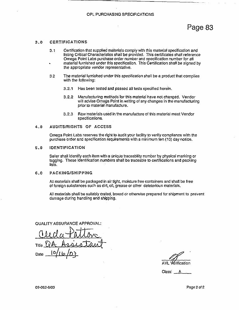
OPL PURCHASING SPECIFICATIONS
Page 83
3.0 CERTIFICATIONS
3.1 Certification that supplied materials comply with this material specification andlisting Critical Characteristics shall be provided. This certificates shall referenceOmega Point Labs purchase order number and specification number for all
- material furnished under this specification. This Certification shall be signed bythe appropriate vendor representative.
3.2 The material furnished under this specification shall be a product that complieswith the following:
3.2.1 Has been tested and passed all tests specified herein.
3.2.2 Manufacturing methods'for this material have not changed. Vendorwill advise Omega Point In writing of any changes in the manufacturingprior to material manufacture.
3.2.3 Raw materials used in the manufacture of this material meet Vendorspecifications.
4.0 AUDITS/RIGHTS OF ACCESS
Omega Point Labs reserves the right to audit ybur facility to verify compliance with thepurchase order and specification requirements with a minimum ten (10) day notice.
5.0 IDENTIFICATION
Seller shall Identify each item with a unique traceability number by physical marking ortagging. These identification numbers shall be traceable to certifications and packinglists.
6.0 PACKING/SHIPPING
All materials shall be packaged in air tight, moisture free containers and 'shall be freeof foreign substances such as dirt, oil, grease or other deleterious materials.
All materials shall be suitably crated, boxed or otherwise prepared for shipment to preventdamage during handling and shipping.
QUALITY ASSURANCE APPROVAL:
'Date't IiAVL cation
Class: A
09-062-8/00 Page 2of 2

......
,PRODUCT CODE: FB/FB
Our customers have grown to expect only thehighest quality products from PMC.
This construction is one of the earliest insula-tons used and is perhaps still the most widelyused. It consists of the single conductorsinsulated with a fiberglass braid then impreg-nated with a special binder to improve moistureand abrasion resistance. The singles are thenlaid parallel and a braided jacket of the samematerial is applied and impregnated.
While wire gauge size, calibration and atmos-phere will affect maximum useful temperaturein applications, This Insulation is designed towithstand a maximum continuous use at 9000 F(4820C) and a single exposure use at 1000l F(5370C). (Note: Impregnations retained to4000F (204-C)).
FIBERGLASS BraidedThermocouple andExtension Wire
DATA SHEET 135
P4,
Calibrated conductorsfor high system accuracy
9000F (482 0C) Braidedfiberglass insulation forabrasion resistance athigh temperatures
9000F (482VC) Braidedfiberglass jacket foradditional flexibilityand abrasion resistance.at high temperatures
/
You will find ourqualified sales andengineering staffeager to assist inselecting a designto meet the require-ments of yourspecific application.Variations of thisconstructionincluding protectivemetal coverings for
PART NUMBERSGRADE OFWIRE
GAUGE WIRESIZE TYPE
I *1* I
TYPE J TYPE K | TYPE T TYPE E TYPE N TYPE RSX
THERMOCOUPLE 16 SOLID J-FM:B.16 K-FBIFB-16 T-FanB-16 E.FB/VB-16 N-FBIFB-16
THERMOCOUPLE 20 SOLID J-FB/FB-20 K4F8B8-20 T-FUBif-20 E-FBIFB-20 N-FB/F8-20
THERMOCOUPLE 20 7/28 STRANDED J-F&FSB20F K-FBFB-20F T-FEIFE-20F E-FB/fB-20F N*FB-2O 20F
THERMOCOUPLE 24 SOLID J-FB/FB-24 X-FB/FB-24 T-FB/FB-24 E-FB/FB-24 N*FB/FB-24
EXTENSION 16 SOLID Jx-FBSFB-16 KX-FaiFD-16 TX-FB/VB*16 EX-FBFB*i6 NX*FBIFB-16 RSXFBIFB-16
EXTENSION 20 SOLID JX4FB/FB-'20 IX-FM/B-20 TX-FE/FB-20 EX-FE/FB-20 NX.FH/FS-20 RSX.F3. F2-20X Ei O 2 0
improved abrasion resistance are availableupon request.
Typical applications include aerospace, alumi-num mills, foundries, ovens, furnaces, heattreating, plastics industry, sensor leads as wellas others.
The above part numbers represent themore popular constructions. However.other designs are available upon request.
PMC CORPORATION57 HarMey RoadLondonderry. NH03053
Tel. (603) 432-9473FAX (603) 4320435

40 1990 PMC Corporation
Color code > THERMOCOUPLE TYPE COLOR CODE | INITIAL CALBRATION TOLERANCES
& initial ANSI .1. I I STANDARD I SPECIAL&alintial WIRE ALLOYS SYMBOL INOIVIOUAL JACKET TEMPERATURE RANGE LIMITS I LIMITS'akbrtan*rn W+ Vs. J W`HffAIED 'BROWN 326F. (OOC) to .545°F (+285-C) -i w .IC
tolerances for Constantanr.) Io cWBLACK +5451F (+285*C to .1400°F (+750 0C) ±.75 ,t__________fo r___ Is________ TRACER 75___ _
thermocouple Chremel(.)vs. K YELLOW/RED BROWN -330 f(-200C) 10 !65'Ft 110°C) -2%wire -1ueT~-)wYLO 1651F(-II C) to 432F ( ±4'-F(22Wire Al~meP(-) ! TRACER +321 (00C) to *545F (+2856C) F .2 C) 2-F51.1 C)TRCE 5459F (.285'C) 10 +2300'F (.1250OC) ±4( %.' j±F¶1Coover () s. IT BLUE/RED BROWN -3301 (2L0C) to -53F (65'C) -1% z.8Constantan-¶.) | w BLUE /85DF (T; 5IC) to +270F (130'C) f 81Z'F (1'C) ±:90F (.5'C)
____TRACER +2704F (+t3O'C) to +660F t+350'C) 75/. +.4%
Chromei T'(+) vs. E PURPLE/RED BROWN -330° (-200°C to -270F (- t70-C) +1 18f(IC;Constanunta ) w/PURPLE -270f (170CC to +480F F +250c) ± 1.7'C tl.BoF 1 *C;
TRACER +4801 +d2!0C) to +64O' +40C :0F 3¶ C t±.4%
____ ____ ____ ___ _ I ____ ___ TRACER_ _ _ _ _ _ _ _ _ _
Color code > *iran vs. Constantn' | JX WHITE/RED |BLACK + 32°F (C-C) to 4400-F (+200'C) t41(2.28 C) i2f(1.1°C& initial ChromeiPlvs.'AiunmeI' KX YELLOWIREOI YELLOW __j 320F (09C) to ..40'F (4-200-C) ±t41 (2.2-C) It2VF (1.1-C,
calibration coprer vs.Constanuan"' | TX BLUEIRED |BLUE -75*F(.60C) to+21O'F(+IOO'C) 2F(1.1*C) ±1f(.5'C)
tolerances for Ciromer-vs. Constantan'| EX PURPLEJRED PURPLE *321F (0C) to +4006F (+2000C) I 13F (1.7 C) ± 2F (1.1 C
extension wire Nicrosii-vs N.5Nii I NX ORANGEIRED ORANGE .321F(0C) to+400'F(+2000C) ±44F(226C) _±2¶F(1aiC;
Copper vs. Copper Alloy SX BLACK/RED GREEN | +75"F(+25*C)to40O0F (4200C) ± 12F (7CC)I I RX
I 161a3;teIc NOTE - Percent tirmt5 Wy air"t to temon r rtoue tn s onts utnt& tor - molfents; ThemofoCoO Mfre cannot be I DIO to m.mt"rjnt ran. t4Souns Mtg Co am aOotsed to our fumomf of IF aoveof oeta. Ole Po -oat (.3R. the fiimts ot=eit r t rnmoeltues betCw me aC
i *.. Lml tS) * (Ttnv 1- 32F) X Ptrcentnte po.0t ufiless %Micsb" St Dint of ourvasw.
NOMINAL NOMINAL NOMINAL APPROX. SHIP.FB/FB > INSULATION GAUGE INSULATION JACKET DIAMETER WT.LBS.physical CHARACTERISTICS INSULATION JACKET SIZE WALLmtC)ESi WALi 1£5iN (INCHIES) PER 1000 FT
properties SPECIFIC GRAVITY 2.54 2.54 16 .006 .006 .080 X .144 22TENSILE STRENGTH 250.000 at 250.000 atP.S~i. (min.) 10000F (537LC) I10000F (5370C)
ELONGATION%(min. 4.8% 4.8% 20 78 .006 .006 .066 X .1l8 11
MINIMUM BEND 5 X O.D. 10 X O.D.RADIUS
ABRASION GOOD GOODRESISTANCE _____GOOO _20 .006 .006 .060X.106 10
CUT THROUGH EXCELLENT EXCELLENTRESISTANCE
MOISTURE GOOD GOOD 24 .006 .006 .048 X .082 6RESISTANCE .
SOLDER IRON EXCELLENT EXCELLENTRESISTANCE
SERVICE 900°Fld82° Cl 900°f(482 C)TEMPERATURE NI NUOUS CONTINU
1000"F (537-C) .10000F (5370C)SINGLE SINGLE
I_______EXPOSURE EXPOSURE
FLAME TEST NON- NON-FLAMMABLE FLAMMABLE
PRICING POLICY >5`- Pf%*C s1.
REELS, SPOOLS & COILS > r 5snSHORTAGES & RETURNS> ,, It<ltr~ C ur .t n tttt s~tu at~n
V ar Lour y. a i N H gSXm oa.
TOLERAHCES > ow sc oerti cmla ard W tredP res cm t vNamlle to Ft=do w m anfm a
-ijt"l CWW" 0s m tcs urcsma a me.dO " god WM VW besOIa to oiacf. 104 11e.er fteeA Itct UommC" M wry aml mrena0t uaIyor avirmatnaft MN M N-da *.eO b~oDS Ov '.0NsOU, Ofbe Os. fNImI~f lO .emeV .0rSS4evtcI .q9 iee PINC c1,00ntuonun asw., s Ueftt be ttsullso.0a.mOr 68.40. CnltOfrm4 ftilao rt t dbt~ 5rU 12113 OrWI11. bCIE Pa ewsa.o ..nl lo lubsnhul WI 48 t.K? 0 b1O.I IA itf'c

es: ST t'o 9t bIdIz0 Bamd
CTO: OMEGA POINT LABS,
16015 SHADY FALLS FELMENDORF.TX 7811:USA
PMC6801H
Page 86A DIVISION OF ROCKBESTOS-SURPRENANT CABLE CORPORATIONAYWAPRD TRFFT MANCFHFTFR.NH Nln1Q3 (f60i 6r.2-350
SPECIALIZING IN WIRE & CABLE FOR THE SENSOR INDUSTRY FAX (800) 639-5701
CERTIFICATE OF CAL113RATIONSPOOL # 0048437E
REVISED
INC. Date: 10/23/2003ROAD Cust PO#: MS1419Q-OPL2 JOB # PS0063934-1
*CALIBRATION RESULTS ARE TRACEABLE TO THE NATIONAL INSTITUTE OF STANDARDS ANDTECHNOLOGY (NIST) AND MEET SPECIAL LIMITS DEVIATION TOLERANCES AS DEFINED IN ISA MC96.1(FORMERLY ANSI) AND ASTM E 230-03. MS1419Q-OPL.
TEST RESULTS FOR: PMC PIN: KK-FBIFB-24 Total Footage: 2400'
Test Temperature(6F)
Inside End Outside End
2000 -0.2 -0.2
4000 -0.8 -OA
600° -1.5 -1.4
800o -2.7 -1.9
10000 -1.4 -0.6
REPORTED RESULTS ARE DEVIATIONS FROM TEST TEMPERATURES. FOR CORRECTION FACTORSREVERSE THE SIGNS.
THE MATERIAL REFERENCED ABOVE HAS BEEN CALIBRATED UTILIZING TECHNIQUES CONSISTENT WITH THEGUIDELINES SET FORTH IN ANSI Z540-1 AND ASTM E-220-02. THIS IS TO CERTIFY THE MATERIAL FURNISHED ON THISSHIPMENT ARE IN CONFORMANCE WITH THE REQUIREMENTS, SPECIFICATIONS, AND DRAWINGS OF THE ABOVEREFERENCED CUSTOMER PURCHASE ORDER. INSPECTION AND TEST RECORDS ARE ON FILE AND AVAILABLE FORCUSTOMER REVIEW.
SECONDARY STANDARD THERMOCOUPLE: TYPE KREEL # POS LEG: 291335REEL# NEG LEG: 291346CALIBRATION DATE: 3/17/00
DIGITAL VOLT METERMODEL: KAYE INSTRUMENTS: X1525S*SERIAL# 306172CALIBRATION DUE DATE: 01/20/2004
ICE POINT THERMOCOUPLE REFERENCEMODEL, KAYE INSTRUMENTS: K-170-SPSERIAL #: 306179CALIBRATION DUE DATE: 0112712004
NIST #: 263094C&A263094B&D
(SINGLE USE THERMOCOUPLE FROMCALIBRATED REEL)
EDC iOORC SERIAL # 15075NIST N 811/26796603DUE: 12117/2005
TYPE T STANDARDREEL # 25926 & 26369NIST # 258779B
Qy-AIIA Cool -W,-71f QUOLITYASSURANCETECHNl IAN DATE
A memb~rof the Matmon Vroup efcompnrits
**6 I t ~^ ItI LeAV1 A I .ltIU

6S:ST tO, 9T 8d
Page 87rv
TO: OMEGA POINT LABS. I16015 SHADY FALLS RELMENDORFTX 781 1ZUSA
PMC6801
A DIVISION OF ROCKBESTOS-SURPRENANT CABLE CORPORATIONJAYWARD STREET MANCHESTER, NH 03103 -(6031 622-3500 -
SPECIAUZING IN.WIRE & CABLE FOR THE SENSOR INDUSTRY FAX (800) 639-5701
CERTIFICATE OF CALIBRATIONSPOOL # 00484378
REVISED
NC. Date: 10/23/2003,OAD Cust PO#: MS1419Q-OPL
JOB # PS0063934-1
CALIBRATION RESULTS ARE TRACEABLE TO THE NATIONAL INSTITUTE OF STANDARDS ANDTECHNOLOGY (NIST) AND MEET SPECIAL LIMITS DEVIATION TOLERANCES AS DEFINED IN ISA MC96.1(FORMERLY ANSI) AND ASTM E 230-03. MSI419Q-OPL..
TEST RESULTS FOR: PMC P/N: KK-FB/FB-24 Total Footage: 5000'
Test TemperatureO*F)
Inside End Outside End
I .,2000 +0.1 +0.5
4000 -0.4 . +0.1
6000 +0.5 +0.2
8000 -1.9 -1.5
10000 -0.9 -0.6.
REPORTED RESULTS ARE DEVIATIONS FROM TEST TEMPERATURES. FOR CORRECTION FACTORSREVERSE THE SIGNS.
THE MATERIAL REFERENCED ABOVE HAS BEEN CALIBRATED UTILIZING TECHNIQUES CONSISTENT WITH THEGUIDELINES SET FORTH IN ANSI Z540-1 AND ASTM E-220-02. THIS IS TO CERTIFY THE MATERIAL FURNISHED ON THISSHIPMENT ARE IN CONFORMANCE WITH THE REQUIREMENTS. SPECIFICATIONS. AND DRAWINGS OF THE ABOVE .. .REFERENCED CUSTOMER PURCHASE ORDER. INSPECTION AND TEST RECORDS ARE ON FILE AND AVAILABLE FORCUSTOMER REVIEW.
I
SECONDARY STANDARD THERMOCOUPLE: TYPE KREEL # POS LEG: 291335REEL-#NEGLEG: 291346CALIBRATION DATE: 3/17/00
DIGITAL VOLT METERMODEL: KAYE INSTRUMENTS: X1525SSERIAL # 306172
CALIBRATION DUE DATE: 01/20/2004
ICE POINT THERMOCOUPLE REFERENCEMODEL. KAYE INSTRUMENTS: K-170-SPSERIAL #: 306179CALIBRATION DUE DATE: 01/27/2004
A, rmber ch ii
NIST M: 263094C&A263094B&D
(SINGLE USE THERMOCOUPLE FROMCALIBRATED REEL)
EDC 100RC SERIAL # 15075NIST # 811/267966-03DUE: 12/1712005
TYPE T STANDARDREEL # 25926 & 26369NIST # 258779B
QA(UA 10 L-0 3
PalI RUflTIY ASSURANCE TECHNICNth Mmen crvp yccnPaniCs
DATE
itO 1oJt-nn7n,.-.. ..... I
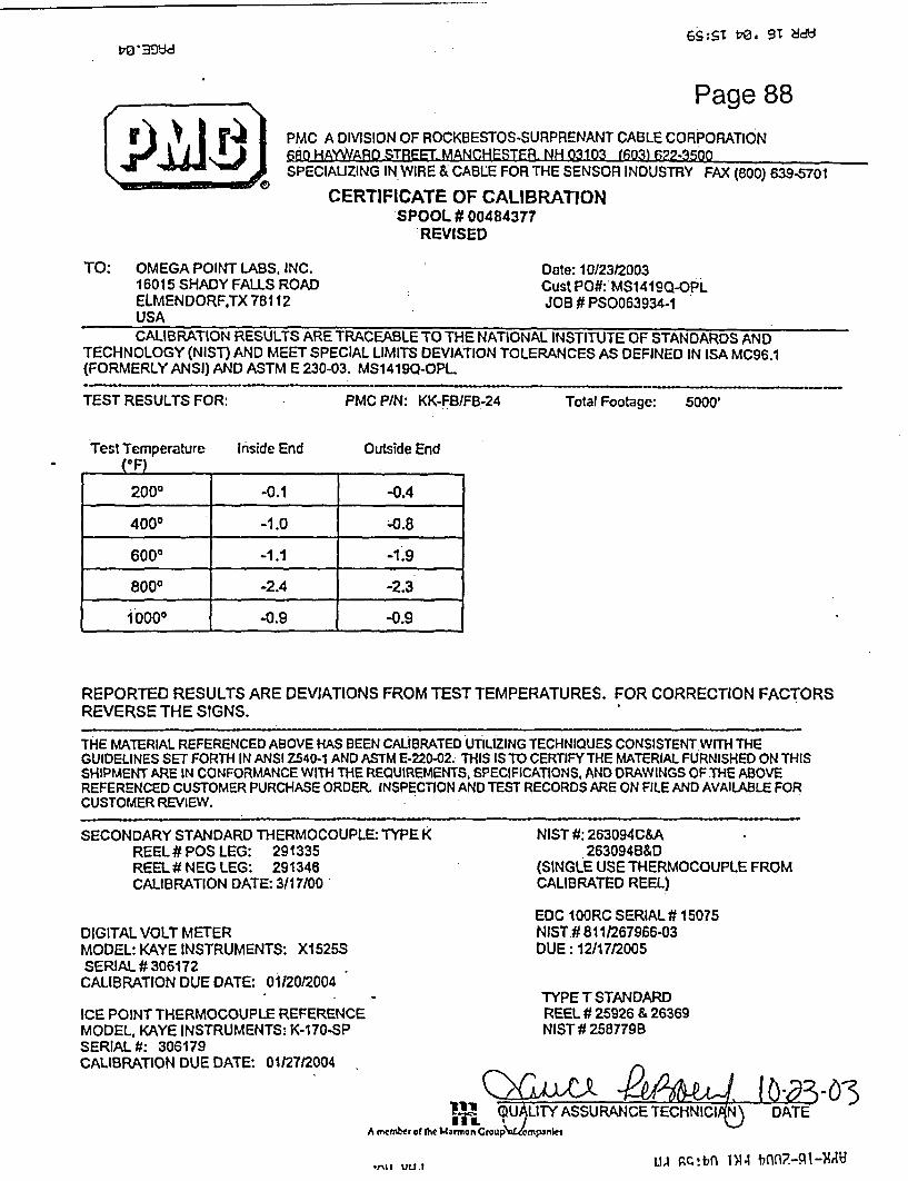
6,S:ST VO. 9T 8dUt d0'39d
rPage 88
PMC A DIVISION OF ROCKBESTOS-SURPRENANT CABLE CORPORATION680 HAW/A-D STREET MANCHESTER. NH 03103 (603) 622-3500SPECIAUZING IN WIRE & CABLE FOR THE SENSOR INDUSTRY FAX (800) 639-5701
CERTIFICATE OF CALIBRATIONSPOOL # 00484377
REVISED
TO: OMEGA POINT LABS, INC. Date: 10123/200316015 SHADY FALLS ROAD Cust PO#: MS1419Q-OPLELMENDORFTX 78112 JOB # PS0063934-1USACALIBRATION RESULTS ARE TRACEABLE TO THE NATIONAL INSTITUTE OF STANDARDS AND
TECHNOLOGY (NIST) AND MEET SPECIAL LIMITS DEVIATION TOLERANCES AS DEFINED IN ISA MC96.1(FORMERLY ANSI) AND ASTM E 230-03. MS1419Q-OPL.
TEST RESULTS FOR: PMC P/N: KK-FB/FB-24 Total Footage: 5000'
Test Temperature Inside End Outside End
REPORTED RESULTS ARE DEVIATIONS FROM TEST TEMPERATURES. FOR CORRECTION FACTORSREVERSE THE SIGNS.
THE MATERIAL REFERENCED ABOVE HAS BEEN CALIBRATED UTILIZING TECHNIQUES CONSISTENT WITH THEGUIDELINES SET FORTH IN ANSI Z540-1 AND ASTM E-220-02. THIS IS TO CERTIFY THE MATERIAL FURNISHED ON THISSHIPMENT ARE IN CONFORMANCE WITH THE REQUIREMENTS, SPECIFICATIONS. AND DRAWINGS OF THE ABOVEREFERENCED CUSTOMER PURCHASE ORDER. INSPECTION AND TEST RECORDS ARE ON FILE AND AVAILABLE FORCUSTOMER REVIEW.
SECONDARY STANDARD THERMOCOUPLE: TYPE KREEL# POS LEG: 291335REEL# NEG LEG: 291346CALIBRATION DATE: 3/17/00
DIGITAL VOLT METERMODEL: KAYE INSTRUMENTS: X1525SSERIAL # 306172CALIBRATION DUE DATE: 01120/2004
ICE POINT THERMOCOUPLE REFERENCEMODEL. KAYE INSTRUMENTS: K-170-SPSERIAL #: 306179CALIBRATION DUE DATE: 0112712004
NIST #: 263094C&A263094B&D
(SINGLE USE THERMOCOUPLE FROMCALIBRATED REEL)
EDC 100RC SERIAL# 15075NISTW 811/267966-03DUE: 12/17/2005
TYPE T STANDARDREEL # 25926 & 26369NIST # 258779B
1-1
Ve'i( U LllY ASSURANCE TECHNICIt)A mcmber of the Mamrron Groupw!cmpniet
ThUr3-ODATE
Lu RC.!bnl 1N4W 7.4lfl-NI~AU.,.tl IJL1.,

6S:ST t'O, 91 .8dso -33d
Page 89
TO: OMEGA POINT LABS, I16015 SHADY FALLS RELMENDORFTX 78112USA
PMCfia0l
A DIMlSION OF ROCKBESTOS-SURPRENANT CABLE CORPORATIONIAYWARD STREET MANCHFSTER- NH nn1n3 (RFll f;7.-flfn
SPECIAUZING IN WIRE & CABLE FOR THE SENSOR INDUSTRY FAX (eoo) 639-5701
CERTIFICATE OF CALIBRATIONSPOOL # 00485975
REVISED
NC. Date: 10/2312003QOAD Cust PO#: MS1419Q-OPL
JOB # PSO063934-1
CALIBRATION RESULTS ARE TRACEABLE TO THE NATIONAL INSTITUTE OF STANDARDS ANDTECHNOLOGY (NIST) AND MEET SPECIAL LIMITS DEVIATION TOLERANCES AS DEFINED IN ISA MC96.1(FORMERLY ANSI) AND ASTM E 230-03. MS14190QOPL.
TEST RESULTS FOR: PMC PIN: KK-FB/FB-24 Total Footage: 4000'
Test Temperature(F)
Inside End Outside End
2000 +0.6 +0.3
4000 4-0.6 +0.3
6000 -0.8 -0.9
8000 +0.8 +0.7
10000 +1.0 +1.5
REPORTED RESULTS ARE DEVIATIONS FROM TEST TEMPERATURES. FOR CORRECTION FACTORSREVERSE THE SIGNS.
THE MATERIAL REFERENCED ABOVE HAS BEEN CALIBRATED UTILIZING TECHNIQUES CONSISTENT WITH THEGUIDELINES SET FORTH IN ANSI Z540-1 AND ASTM E-220-02. THIS IS TO CERTIFY THE MATERIAL FURNISHED ON THISSHIPMENT ARE IN CONFORMANCE WITH THE REQUIREMENTS. SPECIFICATIONS. AND DRAWINGS OF THE ABOVEREFERENCED CUSTOMER PURCHASE ORDER. INSPECTION AND TEST RECORDS ARE ON FILE AND AVAILABLE FORCUSTOMER REVIEW.
SECONDARY STANDARD THERMOCOUPLE: TYPE KREEL # POS LEG: 291335REEL# NEG LEG: 291346CALIBRATION DATE: 3/17/00
DIGITAL VOLT METERMODEL: KAYE INSTRUMENTS: XX1525SSERIAL # 306172
CALIBRATION DUE DATE: 01/20/2004
ICE POINT THERMOCOUPLE REFERENCEMODEL, KAYE INSTRUMENTS: K-170-SPSERIAL #: 306179CALIBRATION DUE DATE: 0112712004
NIST X: 263094C&A26309418&D
(SINGLE USE THERMOCOUPLE FROMCALIBRATED REEL)
EDC 100RC SERIAL# 15075NIST # 811/267966-03DUE: 12/17/2005
TYPET STANDARDREEL # 25926 & 26369NIST #2587798
l {ALITY ASSURANCE TECHNIIA DATEA rmbtrtf the Mjrmon Cry e cfniparnks
LIA nc!bn 7344 bnn7.-:qi-xA9Jw VUJ

r r4l PMC A
\!M)* 680 HA!K s1 SPECIA
TO: OMEGA POINT LABS, INC.16015 SHADY FALLS ROADELMENDORF,TX 78112USA
DIVISION OF ROCKBESTOS-SURPRENANT CABLE CORIPage 90MYWARD STREET. MANCHESTER. NH 03103 (603) 622-3500,LIZING IN WIRE & CABLE FOR THE SENSOR INDUSTRY FAX (800) 639-5701
CERTIFICATE OF CALIBRATIONSPOOL# 00485975
Date: 10123/2003Cust POM: MS1419Q-OPLJOB # PS0063934-1
CALIBRATION RESULTS ARE TRACEABLE TO THE NATIONAL INSTITUTE OF STANDARDS ANDTECHNOLOGY (NIST) AND MEET SPECIAL LIMITS DEVIATION TOLERANCES AS DEFINED IN ISA MC96.1(FORMERLY ANSI) AND ASTM E 230-03. MS12985Q-OPL.
TEST RESULTS FOR: PMC P/N: KK-FB/FB-24 Total Footage: 4000'
Test Temperature(OF)
Inside End Outside End
2000 +0.6 +0.3
4000 +0.6 +0.3
6000 -0.8 -0.9
8000 ° +0.8 +0.7
10000 +1.0 +1.5
Calibration Certificate Acceptance
ItemAwo) a
ISTTraceility-Adcqti. $ MAs Found/Aa Ift Value s
Tleranice lItgc Adequate 3teo3/43 ot/ifa
OPL QA/QC Depth g i g
REPORTED RESULTS ARE DEVIATIONS FROM TEST TEMPERATURES. FOR CORRECTION FACTORSREVERSE THE SIGNS.
THE MATERIAL REFERENCED ABOVE HAS BEEN CALIBRATED UTILIZING TECHNIQUES CONSISTENT WITH THEGUIDELINES SET FORTH IN ANSI Z540-1 AND ASTM E-22X-02. THIS IS TO CERTIFY THE MATERIAL FURNISHED ON THISSHIPMENT ARE IN CONFORMANCE WITH THE REQUIREMENTS, SPECIFICATIONS, AND DRAWINGS OF THE ABOVEREFERENCED CUSTOMER PURCHASE ORDER. INSPECTION AND TEST RECORDS ARE ON FILE AND AVAILABLE FORCUSTOMER REVIEW.
SECONDARY STANDARD THERMOCOUPLE: TYPE KREEL# POS LEG: 291335REEL# NEG LEG: 291346CALIBRATION DATE: 3117/00
DIGITAL VOLT METERMODEL: KAYE INSTRUMENTS: X1525SSERIAL # 306172
CALIBRATION DUE DATE: 01/20/2004
ICE POINT THERMOCOUPLE REFERENCEMODEL, KAYE INSTRUMENTS: K-170-SPSERIAL,#: 306179CALIBRATION DUE DATE: 01/27/2004
NIST #: 263094C&A263094B&D
(SINGLE USE THERMOCOUPLE FROMCALIBRATED REEL)
EDC 100RC SERIAL # 15075NIST # 811/267966-03DUE: 12/17/2005
TYPE T STANDARDREEL # 25926 & 26369NIST #258779B
Q)GtcL A c e P1JJ -2 , O(U)JALITY ASSURANCE TECHNI(QN
A member of the Marmon Group of companies
DATE

TO: OMEGA POINT LABS16015 SHADY FALLSELMENDORF,TX 781USA
PMC A6.80 HA'
X DIVISION OF ROCKBESTOS-SURPRENANT CABLE CORFUagei9 1NYWARD STREET. MANCHESTER. NH(03103 (30t 3 622-3500
SPECIALIZING IN WIRE & CABLE FOR THE SENSOR INDUSTRY FAX (800) 639-5701
CERTIFICATE OF CALIBRATIONSPOOL # 00484377
, INC. Date: 10123/2003ROAD Cust POO: MS1419Q-OPL12 JOB # PS0063934-1
CALIBRATION RESULTS ARE TRACEABLE TO THE NATIONAL INSTITUTE OF STANDARDS ANDTECHNOLOGY (NIST) AND MEET SPECIAL LIMITS DEVIATION TOLERANCES AS DEFINED IN ISA MC96.1(FORMERLY ANSI) AND ASTM E 230-03. MS12985Q-OPL.
TEST RESULTS FOR: PMC P/N: KK-FBIFB-24 Total Footage: 5000'
Test Temperature(°F)
Inside End Outside End
2000 -0.1 -0.4
4000 -1.0 -0.8
6000 -1.1 -1.9
8000 -2.4 -2.3
10000. -0.9 -0.9
Calibration Certificate Acceptance
SN t4 4)NIST Trac-a lity Adequate
As Found/As 1efl Wa~u esCallbrntion Data SumcientTolerance Range Adequate ,
DOtLQofAQ Dept.
OPL QAIQC DepL EngJ IDOL Msr.
REPORTED RESULTS ARE DEVIATIONS FROM TEST TEMPERATURES. FOR CORRECTION FACTORSREVERSE THE SIGNS.
THE MATERIAL REFERENCED ABOVE HAS BEEN CALIBRATED UTILIZING TECHNIQUES CONSISTENT WITH THEGUIDELINES SET FORTH IN ANSI Z540-1 AND ASTM E-220-02. THIS IS TO CERTIFY THE MATERIAL FURNISHED ON THISSHIPMENT ARE IN CONFORMANCE WITH THE REQUIREMENTS, SPECIFICATIONS, AND DRAWINGS OF THE ABOVEREFERENCED CUSTOMER PURCHASE ORDER. INSPECTION AND TEST RECORDS ARE ON FILE AND AVAILABLE FORCUSTOMER REVIEW.
SECONDARY STANDARD THERMOCOUPLE: TYPE KREEL# POS LEG: 291335REEL# NEG LEG: 291346CALIBRATION DATE: 3/17100
DIGITAL VOLT METERMODEL: KAYE INSTRUMENTS: X1525SSERIAL # 306172CALIBRATION DUE DATE: 01/20/2004
ICE POINT THERMOCOUPLE REFERENCEMODEL, KAYE INSTRUMENTS: K-170-SPSERIAL #: 306179CALIBRATION DUE DATE: 01/27/2004
NIST #: 263094C&A263094B&D
(SINGLE USE THERMOCOUPLE FROMCALIBRATED REEL)
EDC IOORC SERIAL# 15075NIST # 811/267966-03DUE: 12/17/2005
TYPE T STANDARDREEL # 25926 & 26369NIST # 258779B
( CUA-h I LS4��-DATE(Q4ALITY 'ASSURANCE TECHNIC1
11rnE1 UII a I
A member of the MNirron Group of comparties

r r4 PMC A DIVISION OF ROCKBESTOS-SURPRENANT CABLE CORRageis92680 HAYWARD STREET MANCHESTER. NH 03103 (603) 622-3500SPECIAUZING IN WIRE & CABLE FOR THE SENSOR INDUSTRY FAX (800) 639-5701
CERTIFICATE OF CALIBRATIONSPOOL # 00484378
TO: OMEGA POINT LABS, INC.16015 SHADY FALLS ROADELMENDORF,TX 78112USA
Date: 10/23/2003Cust POM: MS1419Q-OPLJOB # PSO063934-i
CALIBRATION RESULTS ARE TRACEABLE TO THE NATIONAL INSTITUTE OF STANDARDS ANDTECHNOLOGY (NIST) AND MEET SPECIAL LIMITS DEVIATION TOLERANCES AS DEFINED IN ISA MC96.1(FORMERLY ANSI) AND ASTM E 230-03. MS12985Q-OPL.
TEST RESULTS FOR: PMC P/N:. KK-FBIFB-24 Total Footage: 5000'
Test Temperature(OF)
Inside End Outside End
2000 +0.1 +0.5 :-
4000 -0.4 +0.1
6000 +0.5 +0.2
8000 -1.9 -1.5 -
10000 -0.9 -0.6
REPORTED RESULTS ARE DEVIATIONS FROM TEST TEMPERATURES. FOR CORRECTION FACTORSREVERSE THE SIGNS.
THE MATERIAL REFERENCED ABOVE HAS BEEN CALIBRATED UTILIZING TECHNIQUES CONSISTENT WITH THEGUIDELINES SET FORTH IN ANSI Z540-1 AND ASTM E-220-02. THIS IS TO CERTIFY THE MATERIAL FURNISHED ON THISSHIPMENT ARE IN CONFORMANCE WITH THE REQUIREMENTS. SPECIFICATIONS, AND DRAWINGS OF THE ABOVEREFERENCED CUSTOMER PURCHASE ORDER. INSPECTiON AND TEST RECORDS ARE ON FILE AND AVAILABLE FORCUSTOMER REVIEW.
SECONDARY STANDARD THERMOCOUPLE: TYPE KREEL # POS LEG: 291335REEL# NEG LEG: 291346CALIBRATION DATE: 3/17100
DIGITAL VOLT METERMODEL: KAYE INSTRUMENTS: X1525SSERIAL # 306172
CALIBRATION DUE DATE: 01/20/2004
ICE POINT THERMOCOUPLE REFERENCEMODEL, KAYE INSTRUMENTS: K-170-SPSERIAL #: 306179CALIBRATION DUE DATE: 01/27/2004
NIST #: 263094C&A*263094B&D
(SINGLE USE THERMOCOUPLE FROMCALIBRATED REEL)
EDC 1 OORC SERIAL# 15075NIST # 8111267966-03DUE: 12/17/2005
TYPE T STANDARDREEL # 25926 & 26369NIST # 258779B
A member of the Marmnon Cwvup of c rnanies
I X

..............
r PMC A
SPECIA
TO: OMEGA POINT LABS, INC.16015 SHADY FALLS ROADELMENDORF,TX 78112USA
DIVISION OF ROCKBESTOS-SURPRENANT CABLE COR13ageN93(WARD STREET. MANCHESTER. NH 03103 (603) 622-3500LIZING IN WIRE & CABLE FOR THE SENSOR INDUSTRY FAX (800) 639-5701
CERTIFICATE OF CALIBRATIONSPOOL # 00484379
Date: 10123/2003Cust PO#: MS1419Q-OPLJOB # PS0063934-1
CALIBRATION RESULTS ARE TRACEABLE TO THE NATIONAL INSTITUTE OF STANDARDS ANDTECHNOLOGY (NIST) AND MEET SPECIAL LIMITS DEVIATION TOLERANCES AS DEFINED IN ISA MC96.1(FORMERLY ANSI) AND ASTM E 230-03. MS12985Q-OPL.
TEST RESULTS FOR: PMC P/N: .KK-FB/FB-24 Total Footage: 2400'
Test Temperature([F)
Inside End Outside End
2000 -0.2 -0.2.
4000 -0.8 -0.4
6000 -1.5 -1.4
800° -2.7 -1.9
10000 -1.4 -0.6
REPORTED RESULTS ARE DEVIATIONS FROM TEST TEMPERATURES. FOR CORRECTION FACTORSREVERSE THE SIGNS.
THE MATERIAL REFERENCED ABOVE HAS BEEN CALIBRATED UTILIZING TECHNIQUES CONSISTENT WITH THEGUIDELINES SET FORTH IN ANSI Z540-1 AND ASTM E-220-02. THIS IS TO CERTIFY THE MATERIAL FURNISHED ON THISSHIPMENT ARE IN CONFORMANCE WITH THE REQUIREMENTS, SPECIFICATIONS, AND DRAWINGS OF THE ABOVEREFERENCED CUSTOMER PURCHASE ORDER. INSPECTION AND TEST RECORDS ARE ON FILE AND AVAILABLE FORCUSTOMER REVIEW.
-- -- -----
SECONDARY STANDARD THERMOCOUPLE: TYPE K NI"REEL# POS LEG: 291335REEL# NEG LEG: 291346 (SllCALIBRATION DATE: 3/17/00 CA
EDIDIGITAL VOLT METER NIcMODEL: KAYE INSTRUMENTS: X1525S DUSERIAL # 306172CALIBRATION DUE DATE: 01/20/2004
ICE POINT THERMOCOUPLE REFERENCE RIMODEL, KAYE INSTRUMENTS: K-170-SP NISERIAL-#: 306179CALIBRATION DUE DATE: 01/27/2004
A mcmber d the Marmon Group of companies
ST #; 263094C&A263094B&D
NGLE USE THERMOCOUPLE FROMLIBRATED REEL)
I IOORC SERIAL# 15075ST # 811/267966-03E: 12/17/2005
'PE T STANDARDEEL # 25926 & 26369ST # 258779B
uC ) 2.'ASSURANCE TECHNICIq DATE

PMC Division of RSCC680 Hayward StreetManchester, NH 03103Tel: (603) 622.3500 Fax: (603) 622-7023
SPECIALIZING IN WIRE & CABLE FOR THE SENSOR INDUSTRY
0000105577Page 94
. DELIV.ERY( NOTEDELIVERY TO OMEGA POINT LABS
16015 SHADY FALLS ROADELMENDORF, TX 78112USA
Attention: CLEDA
KK-FB/FB-24Spool #: 00484377 00484378 0048437900485975CALIBRATION CHARGESpool #:
16,400
I

'Certification No.
Calibration Date
Recalibration Da
Manufacturer:
Model No.:
Serial No.:
Equipment Desc
Omega Point Laboratories, Inc.16015 Shady Falls RoadElmendorf, Texas 78112
800-966-5253 FAX 210-635-8101
Certificate of Calibration
92125
3/ 10/04
Lte: 9/10/2004
Yokogawa
100 Channel DAU
99LE004
ription: 100 Channel Data Acquisition System withYOKOGAWA Darwin Series
ces: TEGAM Model 840-A, SN: T-207318.Calibration due 06-04-2004
Calibration Sour
Calibratio Performed by:
M a oMike Dey/Manager of Fire Adistance' . .
Javier TrevinoManager of Special Proj

Page 96Channel Verification for Yokogawa 100 Channel
Serial No.: 99-LE-004
Calibrator Used: Tegam T-20731 8
Temperature Setting (-F): 75.0
Within specs? Yes/No
Performed by: Mike DeyTitle: Mgr. Dept. 2
Approved by.Title: M,<5 ,te <*p,
Date: 3/10/04
Channel No. Readinq (TF) 1 +- Chan1 75.7 0.72 75A 0.43 75.6 0.64 75.6 0.6S 75.6 0.66 75.6 0.67 75.6 0.68 75.6 0.69 75.7 0.710 75.7 0.711 75.2 0.212 75.0 0.013 75.0 0.014 75.2 0.215 75.0 0.016 75.0 0.01 7 75.0 0.01 8 75.2 0.219 75.2 0.220 75A 0.421 75.2 0.222 75.2 0.223 7S.2 0.224 7S.2 0.225 75.2 0.226 75.2 0.227 75.2 0.228 75.2 0.229 75.6 0.630 75.7 0.731 752 0.2.32 75.2 0.233 75.2 0.234 75.0 0.035 75.0 0.036 .75.2 0.237 75.2 0.238 75.2 0.239 7S.2 0.240 75.6 0.641 75.2 0.242 75.2 0.243 75.2 0.244 75.2 0.24S 75.2 0.246 75.2 0.247 75.2 0.2 _
48 75.2 0.249 75.4 0.4 __
S0 75.6 0.6
Range of 75-F Readings: +0.7/-0.2
inel No. jReading (T) ' I +/-515253545556575859606162636465666768697071727374.7576777879808182:8384858687888990919293949S96979899100
74.8 -0.275.0 0.074.8 -0.274,8 -0.275.2 0.275.0 0.075.0 0.0
.752 0.275.2 0.275.2 0.275.6 0.675.2 0.275.2 0.275.2 0.27S.2 0.275.2 0.27S.2 0.275.4 0.475.4 0.47S.7 0.7752 0.2752 0.275.0 0.075.0 0.0752 0.275.0 0.075.0 0.075.2 0.275.2 0.275.4 0.4-75.4 0.4*752 0.275.2 0.275.2 0.275.2 0.275.2 0.275.4 0.475.4 0.475.4 0.475.7 0.774.8 -0.274.8 -0.274.8 .-0.275.0 0.0.752 0.275.2 0.275.0 0.0-75.2 0.275.2 0.275.2 0.2
Allowable limitsLower
73.2Upper76.8 (±1.8)

Page 97
Channel Verification for Yokogawa 100 Channel
Serial No.: 99-LE-004 Within specs? YesJNo
Calibrator Used: Teqam T-2 07318
Temperature Setting (F): 150.0
Performed by: Mike DevTitle: Mcr. Dent.2
Approved by: cTitle: 14J 0 OK
Date: 3/10/04
Channel No. IReadina (*F) I +J- |Channel No. IR eadinmq C) I +J-
234S67891011121314151617181920212223242526272829303132333435363738394041424344454647484950
150.4lS0.4150.4150.4150.4150.4150.4150.4150.1150.1150.1150.1150.1150.1150.1150.1150.1150.1150.3150.1150Q150.1150.1150.1150.1150.1150.1150.61503150.6150.4150.3150.1150.115031 50.150.11503150.3150.6150.31 SO.3150.3150.31 S0.3150.3
150.3150.3150.6
0.40.40.40.40.40.40.40.40.80.80.10.10.1
0.10.10.10.10.10.30.40.30.10.10.10.10.10.10.30.30.60.40.30.10.10.30.10.10.30.30.60.30.30.30.30.30.30.30.30.30.6
51525354555657585960616263646566676869707172737475767778798081828384858687888990919293g94:9596979899100
149.7149.7149.7:149.7149.7
-149.7149.9149.9150.1150.3150.4150.11 S01149.9149.9'150.1150.1150.11503
* 150.61503149.9
,150.1150.1149.9150.1150.1150.115031503.149.7149.9149.9149.9149.9149.9149.9149.91503
* 150.4149.7149.7149.7149.7149.7149.7150.1149.9150.1150.3
40.3-0.3-0.3-0.3-0.3-0.3-0.1-0.10.10.30.40.10.1
-0.1-0.10.10.10.10.30.60.3-0.10.10.1-0.10.10.10.10.30.3-0.3-0.1-0.1-0.1-0.1-0.1-0.1-0.10.30.4-0.3-0.3-0.3-0.3-0.3-0.30.1
-0.10.10.3
Lower148.2
Upper151.8 (±1.8)Range of 1 50O Readings: +0.8/-0.3 Allowable limits
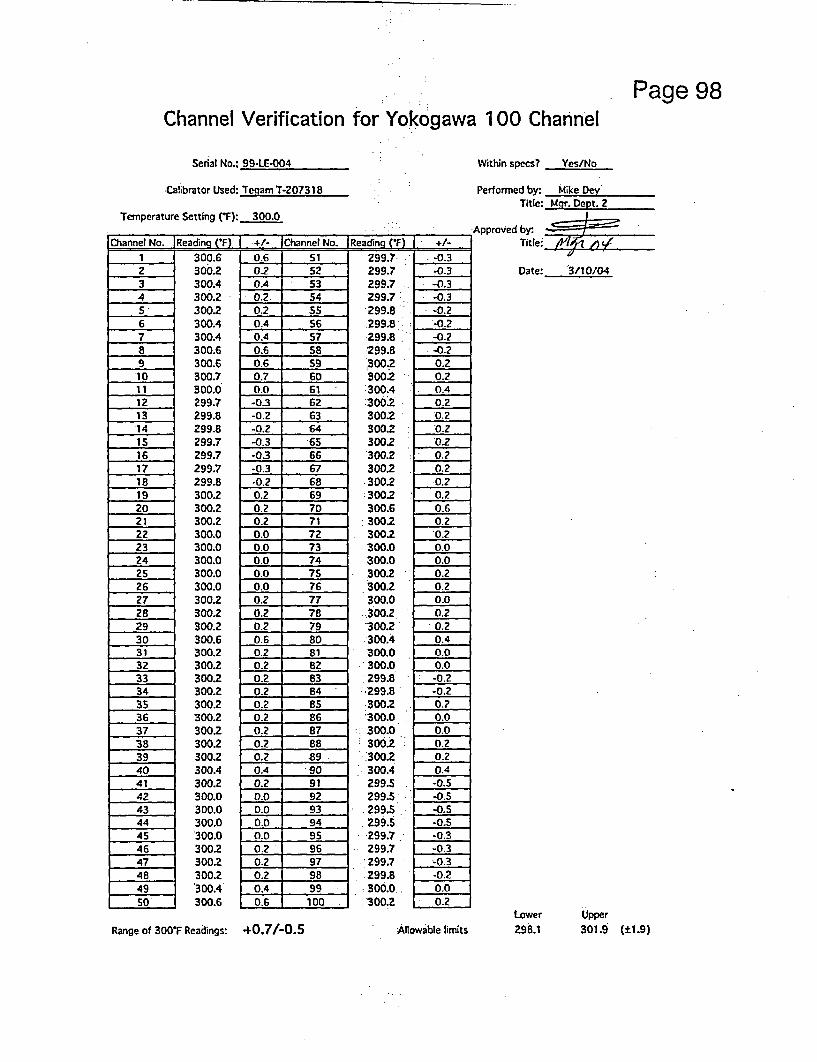
..
Page 98Channel Verification for Yokogawa 100 Channel
Serial No.: 99-LE-004 Within specs? Yes/No
Calibrator Used: Teoam T-2073 18
Temperature Setting (F): 300.0
Channel No. IReadina (F) I +/- IChannel No. A Readina (-F) | +/-1
2345.678.9'1011121314i516171819202122232425262728293031323334353637383940414243444S46474849so
300.6300.2300.4300.2300.2300.4300.4300.6300.6300.7300.0299.7299.8299.8299.7299.7299.7299.8300.2300.2300.2300.0300.0300.0300.0300.0300.2300.2300.2300.6300.2300.2300.2300.2300.2300.23002300.2300.2300.4300.2300.0300.0300.0300.0300.2300.2300.2300.4300.6
0.6020.40.20.20.40.40.60.60.70.0-0.3-0.2-0.2-0.3-03-0.3.0.20.20.20.20.00.00.00.00.00.20.20.20.60.20.20.20.20.20.20.20.20.20.40.20.00.00.00.00.20.20.20.406
51525354Ss565758596061626364i 656667686970717273 i7475767778798081828384 '8586878889
-90919293949596979899 1100
299.7-299.7299.7299.7299.8299.8299.8'299.8,300.2300.2I300.4:300.2300.2300.2300.2300.2300.2-300.2:300.2300.63002300.2300.0300.0300.2300.2300.0300.2'300.2-300.4300.0300.0299.82-99.8300.2300.0300.0300.2300.2300.4299.5299.5299.5299.5299.7299.7299.7299.8300.0300.2
I -0.3-0.3-0.3-0.3
* -0.2-0.2-0.2
I -0.20.20.20.40.2'0.2*0.20.2
* 020.2~0.20.20.6
0.0
0.20.20.00.2
1 0.2
0.0
0.00.20.2
0.4
-0.00.00.2
-0.20.24
1 0.01 0.0
-O02[ 0.2
I-0.5-05 1
I -0.53
i-0.5I 0.3
0.2
Performed by: Mike DeyTitle: Mqr. Dept. 2
Approved by.Title: ,
Date:- 3/10/04
Lower Upper298.1 301.9 (±1.9)Range of 300T Readings: +0.7/-0.5 Aitowable limits

Page 99Channel Verification for Yokogawa 100 Channel
Serial No.: 99-LE-004
Calibrator Used: Tegam T-207318
Temperature Setting (F): 400.0
Channel No. lReainq ('F) I +/- IChannel No. IReadina ff) I +/-
1.234567891011121314151617
- 1819202122
- 2324252627
- 2829303132333435363738394041424344454647484950
400.54003400.3400.3400.5400.3400.3400.5400.6400.8399.9399.9399.9399.9399.9399.9399.7399.9400.1400.3400.1399.9400.1399.9399.9400.1400.1400.1400.3400.5400.3400.1400.3400.1400.1400.1400.3400.1400.3400.S4003400.3399.9400.1400.3400.340034003400.3400.6
0.50.3
0.30.30.50.30.30.50.60.8
-0.1-0.1-0.1.0.1-0.1-0.1-0.3-0.10.10.30.1-0.10.1
-0.1-0.10.10.10.10.30.50.30.10.30.10.10.10.30.10.30.50.30.3-0.10.10.30.30.30.30.30.6
51525354555657S85960616263646566676869707172.73747576777879808182838485868788899091
92 +9 3~9495
97
9899100
399.9a399.9399.7399.9399.9399.9399.9400.1
:400.1400.3400.5400.3400.1400.1400.1400.1400.1400.3400.3400.6400.3400.3400.1400.1400.3400.1400.3400.3400.3400.5400.3399.9399.9399.9399.9399.9400.1400.1400.3400.5399.6399.6399.6399.6399.7399.6399.6399.9399.9400.1
-0.1-0.1-03-0.1-0.0.0
0.1
0.10.10.30.10.30.10.10.1
0.30.10.10.30.30.1
0.3
0.30.10.1
.0.5I0.3-0.10.10.10.3*0.50.1-0.1
-0.4
-0.
-0.4
-0.4-0.1~0.10.3
.0.4-0.4-0.1
-0.1-0.1
Within specs? Yes/No
Performed by, Mike DevTitle: Mgr. Dept. 2
Approved by:Title: p Amp - , y
Date: 3/10/04
Lower Upper398.0 -402.0 (±2.0)Range of 400-F Readings: +0.8/-0.4 Allowable litrnts

Page 100Channel Verification for Yokogawa 100 Channel
Serial No.: 99-LE-004 Within specs? Yes/No
Calibrator Used: Tegam T-207318
Temperature Setting (F): 1000.0
f'6- IoI .-In D-A_ rFM I .u Ithnn In l-Xsfi CA I . . /.*O_ .4mnj lC 4 iI T .~,. c u
I -
23456789
10111213141516171819202122232425262728293031323334353637383940414243444546474849so
1000.61000.61000.41000.61000.61000.41000.61000.61000.61000.91000.01000.01000.01000.01000.01000.01000.01000.01000.01000.41000.41000.21000.01000.21000.21000.21000.41000.41000.41000.81000.41000.01000.01000.01000.01000.01000.01000.01 000.01000.61000o.0999.91000.01000.01000.01000.01000.21 000.01000.01000.6
O.f0.60.40.60.60.40.60.60.60.90.00.00.00.00.00.00.00.00.00.40.40.20.00.20.20.20.40.40.40.80.40.0
0.0
0.0
0.0
0.0
0.0
0.0
0.0
0.60.0
-0.1
0.0
0.0
0.00.0
0.00.00.67
_ = . _ . _
51525354555657S859160616263646566676869707172737475767778798081828384858687888990919Z93949596979899 1
1001
999.7999.7.999.79 999.9999.7999.71000.0999.9999.91000.01000.61000.41000.4100021000.21000.41000.41000.41000.41000.81000.21000.01000.21000.010 oo.01000.21000.211000.01000.41000.6:1000.0
]1000.01000.01000.01000.01000.0
1.1000.011 000.01000.21000.41000.0999.7999.9
.999.91000.01 000.0
'1000.01 000.01000.4
-0.3-0.3-0.3-0.1-0.3-030.0
I.0.1-0.10.00.60.40.40.20.20.40.40.40.40.80.20.0O.20.00.00.20.20.00.40.60.00.00.00.0-0.00.0
10.00.00.20.4
0.0-0.3-0.1-0.1-0.10.00.00.00.00.4
Performed by: Mike DeyTitle: Mqr. Dept. 2
Approved by:Title: L6'M1
Date: 3/10/04
Lower Upper997.7 1002.3 (±2.3)Range of 2000'F Readings: +0.9/-0.3 Allowable limits

Page 101Channel Verification for Yokogawa 100 Channel
Serial No.: 99-LE-004
Calibrator Used: Tegam T-2073 18
Temperature Setting (F): 2000.0
Charnel No.12.34S67.8.910111213141516171819202122232425262728293031323334353637383940414243444S46474849so
IReadina (F) I +/- |Channel No. |Reading (O2000.52000.52000.52000.52000.72000.72000.52000.72000.72001.02000.12000.12000.11999.92000.12000.11999.92000.12000.32000.5i999.91999.91999.91999.91999.92000.12000.12000.12000.32000.72000-52000.32000.32000.32000.32000.32000.32000.32000.52000.7'1999.91999.91999.91999.91999.91 999.91999.92000.32000.32000.5
0.50.50.50.50.70.70.50.70.71.00.10.10.1-0.10.10.1-0.10.10.30.5-.0-0.1
-0.10.1
-0.10.10.10.1
0.10.30.70.50.30.30.30.30.30.30.30.50.7-0.1-0.1-0.1-0.1-0.1
-0.1
0.30.30.5
5152535455.565758596061626364656667686970 171 172 t73 i7475767778 179808182838485868788899091929394
.959697
. 9899100
1999.91999.9
I'--1 99991999.91999.9.1999.91999.92000.12000.32000.32000.72000.'2000.32000.32000.32000.52000.32000.72000.72000.72000.72000.720 Z00.72000.52000.72000.72000.52000.72000.72000.81999.91999.91999.8
.1999.9* 1999.9.1999.8
I 999.9] 1999.5
1999.9.2000.31999.9
, 1999.1.1999.9
1999.11 6999.1
1999.'1999.11999.M
.:2000.1
-0.1-0.1-0.1-0.1-0.1
-0.1
-0.1
* 0.10.30.3
0.7
0.5
0.30.30.3
0.50.30.7
0.70.70.70.70.7-0.5
r 0.7r 0.7I 0.5' 0.7r 0.7
-0.1
-0.2-0.1-0.1
Al l l-0.10.3
-01 .19 -0.1
-0.193 -0.1
93 -0.1
-0.1l 0.1
3 0.3
Aflowvable limit
Within specs? Yes/No
Performed by- Mike DeyTitle: Mar. Dept. 2
Approved by.Title: J
Date: 3/10/04
Lower Uppers '1997.2 2002.8 (±2.8)Range of 2000F Readings: +1/-O.Z

Q/A RECEIVING REPORT
CLIENT/PROJECT NAME F4 CA .&6CLIENTIPROJECT NUMBERJ!&c C
RECEIVED FROM__ E
PEPORT NUMBER.. 24A -3 - OPL-)ATE RECEIVED 5 -5; -0 •)ATE INSPECTE CTED41 .INSPECTED BY_Pfnl ltr.T I lr.ATrlMN rlh-pnen PnintI LnabI& I,} V L V* V .. ...- IVl.^ V
OUANTrI1YE T SAFETY _ _ _ _ _ _
ITEM DESCRIPTION P.O . NO. Ordai Rec'd | I.D. NO. |A YRI YIN AnJT D ANI1 ACCEPTANCE REMAnKS
emo -4wj-C j2 I L 'I V y IY_
IAtI ~ -- 5 6_I ___
| u~ 146(Q o14b Y Y tt=
wcA- &L614~t \' 3'4-37§ jc Y __
.7[00 _ - r
09U61io

PO
po-> 16015 SHADY FALLS RD.
ELMENDORF, TEXAS 78112 PURCHAPH. (210) 635-8100 - .FAX (210) 635-8101
1, . Da.. P11;-
LSE cail 03
K357Q
ate: 04/19/2004,ge: 1 of 11-d
Order From: SSC Lab Division7715 Distribution Dr.Little RockAR 72209501 -562-2900/888-2 78-9292
I eliver to: Omega Point Laboratories, Inc16015 Shady Falls RoadElmendorf( )TX 78112(210) 635-8100
Vendor No: t
Your Item NumberItem Description
Our Reference Qly Ordered Units Unit Cost Extension
0-100psi Pressure Gage tSN:99LE001
0-100psi Pressure GageSN: 98LE001
Dial IndicatorSN: 013021466
Dial IndicatorSN: 013232851 Calibration&Repalr
Load Cell 1k poundSN: 343765 Calibration & Repai
Digital MultimeterSN: 5700109 Calibration & RepaiOW.
Digital Caliper .
SN:6Q-2465-04
200g Weight-SN: 23137
200g Weight-SN: 23138
CAUBRATION CERT. REQUIREMENTS1. Statement of NIST traceability2. NIST test or I.D. number'3. As Found4. As Left Values
I,
001
002
003
004
1.00
1.00
1.00
1.00
Each
Each
Each
Each
Each
Each
Each
Each
Each
$45.00
$75.00
$20.00
$i 20.00
$175.00
$100.00
$70.00
$10.00
$10.00
$45.00
$75.00
$20.00
$120.00
$175.00
$100.00
$70.00
$10.00
$10.00
005
006
007
008
'009
'1.00
1.00
1.00
1.00
1.00
S. Uncertailnties ofcalibratfion"meastrements .
a. Calibraiion data
7. Calibrationcertificates must
show accreditationto ISO/IEC 17025
"See Special Instructions RegardingPurchasing Specificatilons for QualityAssurance RequiremenQA Approval )n . to 4 - ) q -X
Pe.ase Quote Purchase Order Numbkr on all correspondence.
Special Instructions: Pleasc'include Certificate of Conformance toattached Specification Slhect and4 Calibrintion Data traceable toNIST.
. I.
Subtotal:Freight:
Tax Amount:Total Value:
... . I
$620.000.000.00
$620.00
aM

Page 104
VENDOR PURCHASING SPECIFICATION AND
QUALITY ASSURANCE REQUIREMENTS
Vendor: Sa C-Purchase Order No. 14 3 5 - _
Any of the following Quality Assurance requirements shall be incorporated as conditions tothis procurement when corresponding box is marked. Failure to comply with anyrequirement specified may result in rejection and/or return of shipment at seller's expense.
1.0 QUALITY PROGRAM
Seller shall furnish all items on this Purchase Order in accordance withQuality Program approved by Buyer.
2.0 Quality Verification
When additional quality verification activities are required as a condition to thisprocurement, invoices will not be paid until satisfactory completion of such activities.
Receiving Inspection- Buyer shall inspect items upon receipt to verifycompliance with purchase order requirements. Rejected items shall bereturned at seller's expense.
Independent Laboratory Tests- Samples of materials furnished shall betested independently for conformance to specification requirements prior tofinal acceptance. Rejected materials shall be returned at sellers expense.
FA Document Review- Final acceptance shall be based on satisfactory review orrequired certifications and other supporting documents.
3.0 CERTIFICATIONS
When certifications are required as a condition to this procurement, the seller shallfurnish one reproducible copy either with or prior to each shipment. Shipments willnot be accepted and invoices will not be paid until certifications are in buyerspossession.
LII Certificate of Compliance/Conformance Required - Certification thatmaterials and /or services comply with purchase order requirements.Certification shall reference purchase order number and traceability numbers(when applicable).
[] Certified Test Report Required - Certification that material complies withapplicable material specification (s) and the purchase order. Include actualresults of required tests.
5rnrm nO.fnnAi5niJ1

Vendor Purchasing Specifications & Vendor:Quality Assurance Requirements Purchase Ord r
Certificate of Calibration Required - Certification shall be traceable toNational Bureau of Standards. (NIST, Nat'l Inst. of Science & Technology).
4.0 AUDITS/RIGHT OF ACCESS
The buyer reserves the right to audit your facility to verify compliance withpurchase order, code and specification requirements with (10) days notice,
3 Shipments shall only originate form facilities approved by the buyer.
g Buyer reserves the right to inspect any or all work included in this order atseller's facility with as early notice as practicable.
5.0 IDENTIFICATION
[I Seller shall identify each item with a unique traceability number by physicalmarking or tagging. Traceability numbers shall be traceable to certificationsand packing lists.
Seller shall identify each container with a unique identification number. Theidentification number shall be 'traceable to certifications and packing lists.
6.0 1OCFR,PART 21
The material, equipment and/or services to be furnished under this purchaseorder are involved in the testing of basic components of a Nuclear RegulatoryCommission (NRC)' licensed facility. Accordingly, the seller is subject to theprovisions of 10 CFR, Part'21 (Reporting of Defects and Noncompliance)
7.0 PACKING/SHIPPING
MV All materials shall be packaged in air tight, moisture free containers and shallbe free from all foreign substance such as dirt, oil, grease or otherdeleterious material.
Fi All materials and equipment shall be suitable crated, boxed or otherwiseprepared for shipment to prevent damage during handling and shipping.Wherever practical, equipment shall be palletized for ease of unloading andstorage at destination. Each container shall be -clearly marked with buyer'spurchase order number.
QUALITY ASSURANCE APPROVAL ( DATE lq /
Wo^rm no.n:rQ.A/Or/ni Poresm 0 of 0

CERTIFICATE NO: 36283-0003SSC LAB DIVISION Page 1 of.
C*.kI..% .1 h l.'. -. PageI *
CERTIFICATE OF CALIBRATION Cert#1754.01*Quality You Ca-n measure' -Calbration Laoratory
SSC LAB DIVISION certifies thatthis instumentrconforms to original manufacturers specifications or to tolerances indicated0belovand hasbeen calbrated using standards stith accuracies traceable to a National Mbasurement Institute, orto accepted values of natural physical constants,orhave been derived by ratio techniques. This certificate complies -%ith ISOI IEC 17025 & ANSI Z540. Unless othenrise stated, the M& .TE.for which this certificate is issued, based on interprelation of data, mas found to meet the required specification. Reported uncertainty representsexpanded uncertainty at approximately 95% confidence level, coverage factor of k--2.
Customer: OMEGA POINT LAB. Date Received: 4121/04
Location: 16015 SHADY FALLS RD. Date of Issue/Calibration: 04/22/2004ELMENDORF TX78112 Next Calibration Due: 04122/2005
p.o. #:1435?Q- Metrologist: Scan Rainey
Manufacturer: McDANIEL CONTROLS INC. Model: 316SS
Nomenclature: GAGE- PRESSURE Serial Number: 99LE001Range: 0-100 PSI Equipment ID: 99LE001
Calibration Data Temp 68°F Humidity 38%
Calibration Accuracy: :k 2.5% FULL SCALENote: if the AS LEFT column is blank, no adjustments were required.
Note: Many factors may cause outof calibration conditionpriorto due date.The Calibrationintervalhas been specified by the Customer.Current procedures and methods utilized by SSC Lab Division are approved by the Customer.
APPLIED AS FOUND AS LEFT UNCERTAINT' PROCEDURE #
25 LBS 25.78 25.78 2.9 NA17-2OMP-06
50 LBS 51.24 51.24 2.9
75 LBS 76.38 7638 2.9
100 LBS 10132 101.72 2.9
STANDARDS(S) USED
Identification - CWllbraion Expiration TraceabilityNumber Description Date Date Number
SSC30LD029 CALIBRATOR- PRESSURE -7/3012003 713012004 33426-0044
SSC30LD048 TRANSDUCER- PRESSURE 8/11/2003 8/111/2004 1000154760
Calibration Certi.~cate Acceptance
Item _-I OC)I rA°W t QSN9 L IF ( ,
Q/A .EaIST Traslflity Adequate
As Fouund/As Lef Values
Tolerance 7nge AdequateCate of ReviData.SufSde7
OPL QAQC Dept DcpL Mgr.
p
(1'41e-.�, /,
6Gary McCourtChief Metrology Engineer
fnntm n- f......... -
ThM omftirter may not bereproduced, ecx in full, ikhozt thc -rkkn coiisert fSSC Lab DMision
SSC Lab Diviscon, 7715 Distnibution Dr., little Rock, AR 72209 Fonn5.1 0.2-1

Jc.s 14} Rob4I r
Page 107
: /A t*Y St I ZINC. P(,Ar&D AeA-A'
* A 'i2vcF4 -A U, A'*A-,?D
,tefl 1 gc-w e!//ei H@ ff4XK RI
~oh1 ?-LIN 2J et Peicrn
* ( SI1LrTELL-ctrI~t/C 4h ltZ~jWl
O~~~u~,~J-r L4A(I"eiAf2 r%
7S' 6ghL' L-A's rDec I-t%'* G . R3 tJ
X-r , cAC lC 1
to7 70 I t- Ae-A'
>££ce-o
Lto ..
*4 Ab'd Au6eD/, 4~:5e,- :177-
I4Mizkjw f0R "56
Aos VAne
'i// 7 7/0
rcs7O/
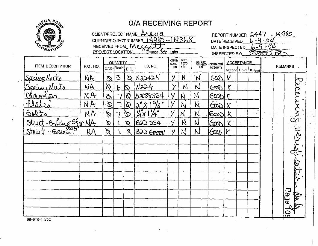
0oAtQ/A RECEIVING REPORT
CLIENT/PROJECT NAMEM
CLIENT/PRIOJECT NUMBER IRECEIVED FROM C
RROJECT LOCATION -0mena P-oint Labs
REPORT NUMBER 94-47 - l DDATERECEIVED _6_ -C ,DATE INSPECTED /n-C -0,^
INSPECTED BY:
OUANTITY . SAFETY
ITEM DESCRIPTION P.O. NO. IOrdORec'd ID. NO. MAR |REI T | crYUME1O ACEPANE REMARKS
Y/N AxIN D N n w N y
y4 ŽL3 K Y
_ _ _ _ _ y I _ __
p -- - - t- -s -. 1 -/ - (0 5 =
CD
-0 - - - -Y
00-016- 1/J02

|ZMEGGITT SHIPPING MEMOPage 109Meggitt Safety Systems, Inc.1915 Voyager Avenue *A SNW C93063 C (805) 5844100
TO: Qrv-5a, Pomt Lcvbof+ors 5109
IG6O V5 SWd Y 41 Is koad DATE 510E16m0 e [-S7 f41- 112d
ATTENTION DEPARTMENT
C on s-an ct 1k>'p h ' CAQ) G3S- I2toPURCHASE ORDER NO SAIPVIA 7 fOB
YOUR REF. THIS SHIPMENT
[3 COMPLETE Q PARTIAL
ITEM OUANTITY PART NOIDESCRIPTION VALUE
_ 7 ec CVCAWg YC 2 o
L 7 , V IkV' -4 53 C e n flzY nu4- U/ 5prr\tS
Lf 7 eq P'tk - 2-" hc S~f'
o 3 ec. KJ2Y2J-2 rul DL*
S tr3a2-oz S-SLi-7 3F4- r'2- &r-Wn s+
COMMENTS OR SPECIAL INSTRUCTIONS
rAUTHORIZATION t-
STOCK PULLED BY SHIPPING CLERK ABOVE DESCRIBED ITEMS RECEIVED IN
. GOOD ORDERSHIPPED VIA WEIGHT BILL NO COMPANY
WEIGHT - LOS NO CARTONS |DATE SHIPPED BY DATE
WHITE.VENDOR / GREEN-VENDOR ACKNOWLEDGEMENT / CANARY-ACCOUNTING / PINK-SHIPPING / GOLDENROD-EXTRA

Page 11.0
r , : SIEZrMATERfA17-, _ . . . -
SUPPLIED BY MEGGITT SAFtY SYStEMS INC
/
QIANTITY UNIT DESCRIPTION
40 LF 8c 112 AWG 512400 FIRE CABLE. PN: 300283-5
NOTE- FACTORY INSTALLED CA1E SPLICE AT APPROX 12' FROM ONE END_ AND FACTORY INSTALLED CABLE TERMINATIONS AT EACH ENDS
* .. -7_ EA CLAMP 8 208 .SS4EA 316 SST HEX SCREW D-LINE 1/4- X 1 1/4- SHHMS
EA 316 SST SPRNG NUT B-LINE N224 SS6
L- EA 2' X I 5/8' X 10 GA'TK 3D4 S5T PLATEL I B-LINE B22 SS4 STRUT (CpS -_ - m
__I _ r D-LINE 822 DURA GREEN STRUT 822 CR1BL 3 EA 0-LINE ZirC ELECTROPLATED SPRING NUT 1/4-20 N224ZN

Q/A RECEIVING REPORTA. � . . �.
CLIENT/PROJECT NAMEI3.UA
CLIENT/PROJECT NUMBER-LJA.2-- REPORT NUMBER 4 q - /49 &°
DATE RECEIVED A_-g -0 <RECEIVED FROMO MPROJECT LOCATION nonena Poinl Labs
DATE INSPECTED -- q -~imqpi~Tpnl riWv. ~ F7 t
~~~~_ _ __ S A E T _ _ _* _ _ _ _ _ _ _ _ _ _ _ _ _ _.......... ar e- _ IOUANTITY MAHEM~ RAELTYOc1AE ACCEPTANCEI.T I .L RELAT RE MARKS
ITEM DESCRIPTION P.O. NO. Ordoa Rec'd B.O. I.D. NO. YN YIN Y!tN U'IEGA1Y | | _ REMARKS
,1ftAktA,,1bDff IUA- 41 b'~ D;=6zr 5 eWU~AhA);U - y
. 0
. I
C
(DQ
LA
CZ)
; �o�r
zt-
i
a
0a-01a-1 1/02

,-,MEGGITTM~IT1 5l3i)1Rt-
0A: \____
05- 12-04
MEGGITT SAFETYSYSTEMS INC
Pag.S,1 2I 2A(C(:lEPIlANCIrl 'VEST DATA SliTET
. FmH
FIREU CABLE ASSFEMBLY
PART NUJMERli: 50E04O F00 03?z8J
TlS'STI ROGRIAM NUMBER: 5181
SERIAL NUMBER:
R0I.iVISON __C
1.0 Dielectric Streuigi11 af room temnperattlre pier STI 2191. Rtevision C
1.1 3200 VI)C betwecii codtiuctor antd sheatl Ifor 60 seconds. No inldicatiof lrea 200* - (snil
-Iechl Staml/Date
1.2 3200 VD)C conductor to conductor for 60 seconids. No idica tion ofr ldownJUNO 4 O 4
Tech Stamp/Date
2.0 Insulation Resistance at room temperature per STI' 2190, Revision C .(All unused pins connected to slieatli. Record values.)
121 1-0 'x 10 ohms 7 1'0 x 10 olinis
2 1.0 x 10 olinis 8 1.0 x 10 ohms
3 1.0 x 10 ohmll1s 9 W/A x 10 ohms
4 .0 x 10 ohmns 10 "/A x 10 ohmtils
5 1.0 x 10 ohmins 11 ,c 10 ohius
6 1.0 x 10 ohmns 12 W/A x 10 ohmns
JUN 04 200~Iech Stamp/Datc
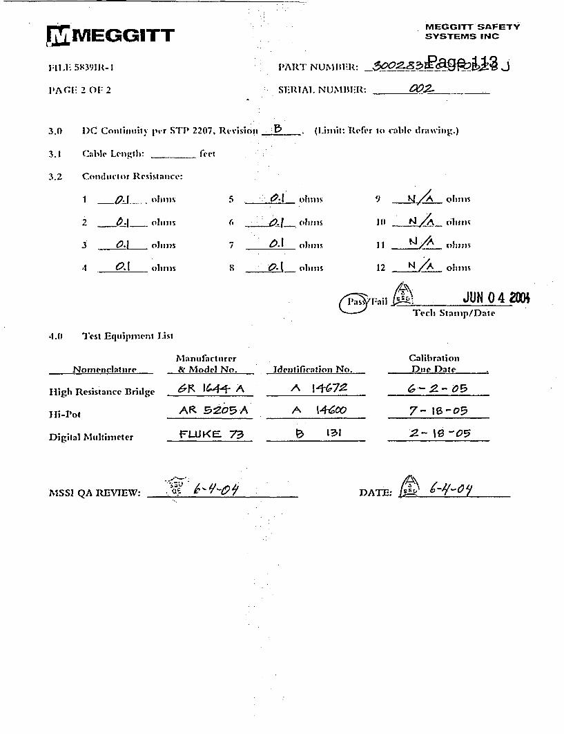
rIMEGGITT1;11,1 i 58391R-1
PAGE 2 01: 2
MEGGITT SAFETYSYSTEMS INC
PART NUMIBliR: _300o28Q agpo J
SERIAL. NUMBER: Z.. ___
3.0
3.1
3.2
D)C Contintiiv per STI> 2207, Revisic)2 - . (limlit: Rtfer to caIlI' dIrawsviIng.)
(Cable Length: _ feet
Conductor Resistatice:
0 .1...~J_ olulltS 5 0. 1~ ,~ 9lll (y o1 h o11S
-2 m1__ olims
3 .~QL. us 7 h. n oiiiiis Il A 01lli11s
,t 0.! Obs 8 - ohuis 12 N A olinis
- 11il .; JUN 04 20-P Tech] Stamip/Date
4.0 Test Equipi-nent List
Nomenclature
High Resistonce Bridge
Ii-rot
Digital Multittieter
1Mlanufactitrer& Model No.
6R IG¶- A
AR 2o05 A
FLUJKF 73
Identification No.
A 11+672
^ 1-46co
_ 1?1
CalibrationDtie D)ate
6--2- 05
7- 16-05
2- 1 -05
NISSI QA REVIEW: NSIQARVEW AT:( -'.c,DA,,: t -+-

,IMEGGITT- MEGGITT SAFETYSYSTEMS INC1915 VOYAGER AVE. SIMI VALLrY, CA. 93063805-584-4100 FAX 805.584-9157
Packing Slip
Ship To: Invoice To:
OM*EGA POINT LABORATORIESATTN: CONSTANCE HUMPHREY210-635-812016015 SHADY FALLS ROADELMENDORF TX 78112
IN-HOUStWIEGGITT SAFE TY SYSTEMtS <1915 VOYAGER AVENUESIMI VALLEY CA 93063 4
I. I
I INSP I PriorityI DT I E
Ii7 o
Ord Date Promised Customer P.O. F:O.B. Contract Administrator10/15/03 11/15/03 Fred Rudek Destination DIANA COX, EXT 8127
Line . Item Number/LocationLot Description Shipped ] Tag Avail. UM Due Date Schedule B7INIMUV3 SAIJ;U.S K lff UI'KUIIU HIM- Cb A I/.Ji %IQRIUUAUKKL. I .ITESTS TO BE PRESENTED TO NRC.lfSSI WIL'- IMA VE JOINT RIGHTS SIARING TIHE QV 4LIFICATIONTO TEST RESULTS
TFST FAC'LITY W)LL BE RFADY F.VD OFNOVEIM1 'R
SPLICE R QUIRED AT MIDPOINT IN CABLE
31.000 300283E10040B281 FIRE CABLE I EA 1115/03' Blank - Sales RFGRev.
Serial #00
_C.CD
-u~~7
.Qrunlity Amsrinci Packer PackerTrack/Alrbill #
1Vign I:
Ship Vial: BEST VAY PREPAY ONLY "', Ja

Page 115. cm . -.
1 E~a"EGGITTMEGGITT SAFETY
SYSTEMS INC
ENGINEERING DEPARTMENT
DOCUMENT
ER 04-033
TITLEUNPACKING, INSPECTION, INSTALLATION AND
STANDARD PRACTICES FOR81C #12 AWG Si 2400 FIRE RATEC CABLE FOR
J.M. FARLEY NUCLEAR POWER PLANT
PROPRIETARY DATATH1S DATA SHALL NOT BE TRANSFERRED. RELEASED,DUIPUCATED. USED OR DISCLOSED IN WHOLE OR IN PART FORMANUFACTURE. OR PROCUREMENT WrTHOUT THE, EXPRESSWRITTEN PERMISSION OF MEGGITT SAFETY SYSTEMS. INC. ALLRIGHTS RESERVED.
_APPROV ALS CONTROLLED j fAPPRVALS_ |DISTRIBUTION
PREPAREI E:t:: n O.A.:, /PRPAE EQ SIZE CAGE CODE: R 04033
A 25693MFG:
REV. A SHEET1 of 8

Page 116
APPROVALS
I -ti-
REV.
A
DATE -DESCRIPTION
a 04 INITIAL RELEASE
-

Page 117TABLE OF CONTENTS
1.0 PURPOSE.............................................................................................................................. 4
.2.0 INSTALLATION AND STANDARD PRACTICES ................................................ ,.,,,.,.4
3.0 UNPACKING AND INSPECTION.4.-.4
4.0 ROUTING AND INSTALLATlON..:..... ............................................................................ 5
5.0 POST INSTALLATION INSPECTION OF SI 2400 FIRE CABLE .6
6.0 TERMINATIONS ................. ,.,.7
.........
SIZE CAGE CODEA 25693 ER 04-033
REVA SHEET 3 OF 8
I1

.........
1.0 PURPOSE Page 118The purpose of this document Is to provide guidelines for installation and field handling of
MSSI Fire Cable.
2.0 INSTALLATION AND STANDARD PRACTICESa. A Si 2400 cable is designed for use In Class 1, Division'1, Group A, B, C and D locations.
When properly Installed, it easily withstands extreme temperatures and high humidity. In
fire danger applications, it continues to perform at temperatures In excess of 20000F.
Cable construction consists of a thin-wall, stainless steel outer sheath, silicon dioxide
dielectric, and nickel or nickel coated copper conductors. Other types of sheaths and
'conductors are also avallable if specified iffe purchase order. Wfien installed in areas '
where chemicals corrosive to stainless steel are present, an outer covering of a cross-
linked polyethylene or similar PVC material can be provided. Cables may be cut to length
and terminated In the field, using ordinary tools and equipment.
b. Meggitt is staffed to provide formal training In the handling and Installation of Si 2400
cables, tailored to specific customer needs. Supervision during actual installation can be
provided to augment classroom Instruction and offers the customer's craftsmen the
advantage of on-the-job training (OJT).
c. This document provides basic guidelines for handling and Installing Si 2400 cables, from
receipt to completion of Installation. Field terminations are described in an accompanying
document, FTP-9234.
3.0 UNPACKING AND INSPECTION
a. Do not remove cable from reels or factory coils until ready to install.
b. Visually Inspect cables for evidence of shipping damage, such as dents, gouges, or kinks.
Small superficial scratches'In the cable sheath will not degrade performance.
c. Do not unroll the cable from 'its shipping container to perform electrical tests.
IMMEDIATELY FOLLOWING ELECTRICAL TESTING, RESEAL CABLE ENDS. The
dielectric must be protected from prolonged exposure to the atmosphere or direct
exposure to water. Cable ends may be resealed with epoxies provided in the termination
kits or with heat shrink boots. lUse of electrical tape for sealing cable ends for extended
periods is not recommended.
SIZE CAGE CODEA 25693 ER04-033
REVA SHEET 4 OF 8
A A

la
4.0 ROUTING AND INSTALLATION Page 119NOTE: EMPHASIS SHOULD BE ON "PLACING" AND "FORMING" RATHER THAN
"PULLING" AND BENDING" THROUGHOUT THE INSTALLATION PROCESS.
a. Visually Inspect the routing path of the cable and note areas that pose a hazard for the
cable. Hazards may Include:'
1. Sharp metal edges, which the cable might be dragged across.
2. Moving machinery or equipment along or adjacent to the planned cable route.
3. Extremely sharp or restrictive bends along the cable path.
4. - .live- -t- n-c*T-arhpaned-roun ath
b. Station a person at each routing hazard noted and at all locations where a change of
direction occurs. As a rule of thumb, the cable should be manned about every 20 feet
during initial Installation.
c. Structural Interferences, which the cable must pass over or around, should be padded.
Bell rollers may be used, but are seldom needed.
d. Cables. must be uncoiled as the cable Is fed out along the routing path. Whether on a reel
or in factory coils, the cable must be unrolled in a tangential (circular) manner. DO NOT
UNCOIL BY PULLING ON THE END AND HELICALLY STRETCHING.
e. Si 2400 can withstand a high pull force as noted In Table 1. In virtually all Installations,
only a fraction of the allowable pull tension Is utilized. Pushing the cable from one
manning point to the next Is by far the easiest technique and has added advantages when
negotiating restricted areas and interferences.
f. When changing direction or bypassing a routing hazard, use large sweeping loops, rather
than tight radii turns. This loose or excess cable will be dressed after the cable'is in place
at both ends.
g. Ensure sufficient length is available to install field terminations prior to final forming. A
minimum of two feet of wrinkle free, round cable is required for the termination, so ensure
the cable end was not bent, twisted, or flattened during cable Installation. If this occurs,
the deformed cable segment must be removed prior to final cable positioning.
SIZE CAGE CODEA 25693 ER 04-033
* _ _ .REV
A SHEET 5 OF 8I * L

h. See Table 1 for minimum advisable bend radius of Si 2400, but be awl ?34QObendinglstraightening in the same location is potentially more harmful than a tight bend
that is left in position. The stainless steel sheath may become weakened or work
hardened during repeated bending, resulting in severe wrinkles, kinks or stress cracks.
CABLE WALL MINIMUM MAXIMUMDIAMETER THICKNESS BEND RADIUS - PULL FORCE
0.592 In. 0.015 In.' 6 In. (nom) 500 lbs.
Any smooth surface or appropriate radius may be used to forrn the cable. EMT tube
_ suitabensrle and are normally readily available. In
many cases, the cable can be hand formed.
1. Cable runs should be supported at least every eighty-one Inches and within approximately
three feet of the beginning or end of a bend or 2 450. See Table 2 for recommended cable
mounting and support options for cable runs.
j. Si 2400 Fire Cable may be routed in cable trays; Stainless steel trays are recommended.
Cable should not be installed in galvanized trays and should NOT be in direct contact with
galvanized or aluminum trays or structures.
TABLE 2- Cable Mounting and Attachment
I. B-line stainless steel strut.
2. BB-Une Part No B2088SS4 clamps for a 0.592 Inch dia.Cable.
3. Standard hardware for single hole clamp.
4. Panduit stainless steel ty-wraps or equivalent.
5.0 POST INSTALLATION INSPECTION OF Si 2400 FIRE CABLE
a. Smooth, contour changes such as dents, dings, ripples, or wrinkles are acceptable except
in areas where termination kits must be installed. See Figure 1
b. Kinks or wrinkles whose upper radii are extremely pronounced or touching Indicate a
potential problem area, as straightening may result In cracking the sheath. See Figure 1.
c. Gouges or cuts in the cable sheath which exceed 10% of cable wall thickness may be
cause for rejection. Wall thickness Is normally .015. The depth of gouges or cuts should
be calculated based on a measurement of the distance from the root point of the gouge or
SIZE |CAGE COD I- A 25693 .ER04-033
I REVA SHEET 6 OF 8
I L

cut to the direct opposite point on the cable O.D. and known O.D. of tRage 1 21Recommend measuring lnstrument:blade or point micrometer.
d. Electrical continuity and installation resistance should remain essentially the same as pre-
installation test results. Any significant difference, even If within acceptable limits, should
be investigated:
6.0 TERMINATIONS
a. Si 2400 Fire Cable may be purchased with factory terminating pigtails on one or both ends,
or terminating kits are available for field use.
_. j.xTejminations. whether factory or field Installed, are designed for attachment to junction or.. . .
.1 . . _ .. ._ _ ......_ ._ __ - . _ ...........
_
terminal boxes such as Hoffman's. Standard fittings such as Myer hubs or lock nuts and
bushings are acceptable.
1.
SIZE ] CAGE CODE_A |25693 ER 04.033
IREV
A SHEET 7 OF 8a. * ________________

Page 122
ACCEPT REJECT
.I
II I
. .. . . - ...
SMOOTHDENTS, DINGS
SCRATCHES.CUTS < 10c WALLTHICKNESS
WRINKLESS i}- jRIPPLES
. , ,, ... . . . . . .. ... .. .. ... .. . . .... ..... .
SCRATCHESCUTS >10% WALLTHICKNESS
KINKS - WRINKLES AREVERY PRONOUNCED.POSSIBLY TOUCHINGAT TOPS
FIGURE 1 - Si 2400 FIre Cable Inspection Criteria
SIZE I CAGE CODEA 25693 ER 04.033
4
REVA SHEET 8 OF 8
I

Q/A RECEIVING REPORT
CLIENT/PROJECT NAME__ NAM_ REPORT NUMBER ?AAt -_CLIENT/PROJECT NUMBER 1 Jm - I 3 1 I DATE RECEIVED b- - 4RECEIVED FROM HeJN1 - DATE INSPECTED_ PE GTE,PROJECT LOCATION_ Omega Point Labs INSPECTED BY:_ _ _ _ _
QUATIY car SAMEY CT1 ACCEPTANCE0 NTITYMATL R= RELATEDCOr
ITEM DESCRIPTION P.O . NO. Ordet I.D. NO. YIN YINM GRf c A Hnld i REMPaAKS l
js*3" 8 I ' ___ .____
:~~~ - - . '"_ _,. _=_ = _- -...... .-. -' ' .:
- -. . -_ - - -
09-010-1 1102

........
...-.16015 SHADY FALLS RD..�.1, -4-, , -;l: , , � -:� , �i1:._�,.I.I. _. . .,�- .I. ..-. I.- IC..--�I- I�
.�., �,.i'.. - ,-. - �. � . - ,,.,� :, r -�. . ,2:-� I-,..,-�;��-� -� :, , ,, ,:�ELMENDORF. TEXAS 78112�� :� ,'OR,.. � 4 �
.- ,_� ,2, -PURCHASE, DEW -,�::,: - ,_�9)_ -PH. (210) 635-8100..:; , -- ,�-,... .,.".;_ '...-'r � .: � -, �� ,i t,: � :�. ..,42 -!_-_ ,_::-, :'. -��!T , .. ,,,'': .�-.�,.I;',',: . �� ,; .,'",�I.-I . �.�� ; ","� .. ,"dj6p %'V FAX (210) 635-8101�, ��,, ,, , .�,, . L �.. I1:,, :, ,. :e--,, :: .: ,-:.;.i !,, ;,� , ,�. :-.,�,I��:-. I�I. . -.. � -.. - :, �"
"',: :,,�,�. 11 r,-,'. �5." .':..:71 ,�� - ,-. �...,Pagp.,l 24: ' -104AT61; .:.� .- ... :ai �.�- :...1. .. . ... -. �... . . I. : .. ... :.. �14427U- -. .. �.. �. ... �.� . �. � �.. Date: 6/8/2004. . .... �� .�....Page: 1 of"I -�.
,-i! ;7" �..;.,�.�'.�-,!�i�--�",:�'��:"�-..'��-,.--,'�",�i-'��;.-".��'-,,��.�,�'..,'�,��':'�,,�,'-",�-,, ''. :".���!,:;!!;-",�;���:.�,.-��"-",..,"��'; ." ", . , � .I .1--.1_I� 1:..11i,.�.;�-i , �-i:i�;:,_��,-Vtl!!..c- ..!-, .. .....- �.,�.�'. � I, - "'- - ,' - ' ' __ .. -- " 41!,, .-" '. , .1 -. , ! : .� :. , " ', - , , , � , ': - " -,' ". ,!,� - - � -, I � ,, ,, , , " , "�,�,�, , , - - �11'��!- '. ,I ", �:`;j;� � r-1�__ " `-�--.- ,,11:,I .
���- ,� , .. . 1. .., I'l.,, ,.: 'i. I ., �:,'.: :." �;�,,�_�,!-:.., � ", .; �-_ -.. ,,� '!-..::_' 7', 1�!__-'. L,�� -. :�,- .iL,. .2,,--.�, 1��. : .�� ., ",,- ,:- -;'',_ ,:�',,' ", �, -"�:!! .",, �,','.. �..:"��::.;., 4 _,_: -t, - -�- - - -� , , �:!. �:!: . - - - .� .!
,.� '.,��� .. ,� . ;:" .:�...,--,-;"', ::." i!,! ;:._, ;." --. , '' --- t�- �;.ZI, _ ,-� -.. ��;,------...:'-� '.�-�.....---- I -":I- .,.,.:.,...�.1-.I.1... . .��--... ,;: ..:.tl . �, " _- �-',�_i, ��,!,�'!."�i!,�.--!�'..-�.;11. � � ,,-�! I-: -. �::,lw 1. "...:,: 1, ; �.! '. - :-__,:.-- ,�:, - .: i .. � " " : ..,;�i.. � .. .- --- -�.-- ra: :, �.:. i .,-,,.;, .! -, .. .,; b: .. ;'. ".. .,. I-:. . . � .- -;: �. . -. 1. :::.:'- :. I-, L�I;� ��-,_ ,-�,-.. �. 1� . ,-, -,,�..I-,.-,:�-, ,,� .'� � . �. _� .,..�::!1.-, . .. , . - I � ,:��:;,:,��;��.. , �,�. - . I . , , , - , "I,I. !., :... ._ ... ,,. -,�- :,,z .-. ,,��,.-. ��,-- -. ,. .. . .:�.!':-., "', ., .11 :..I.III �,,�.. ,:-�� % .. -, ,,, , .. , , , -_ � I. � ., -,.1', � " �`: ,..L ." , � , ,,. . . ,- , - - .,. , , :.:: :,,:.:- o ', �... .... - � �., _ :�-.S ,. � . a-., -, i� .. .- , �1! :, . : : �; -.- : .,-1 11 . s . . . .�.I :I�.� ,, , :� i :- ":., , -...-..-.' ''m o koh-V or `;l'!.'�:., .... ' -l1: �-.. I. --- -:Order From: Alas- -- -`�`t�.---1. � ,.:.,'.' :� � . . , . .:I.I �-.., :, ":,�, k �-,.�'D 6'li'v`e'r':tfo- -bri:idga: 136i t tab6r`ato'd66 166 �:�':,.'..I � - - ��,. ..- - -' '. -� :., :. . .. ,-.. : I:- f. �-.- �.:- ....��I�.:�. .-.%..:.:.,.:.... .. .. . .. .. ...,II.I.�''':�. '', ' "': 16015'Shady' Falls' Roa .: , -:.: -"; .,:, !,;��,� .I': ! - :,.. .f' ' ;'M 'SBC 'Ce'nte'r Piikvv� :1... . ,-... ., �d -.. .. �...-.-.. '.. .. I:......San Ant6n'o'I. .. L
. . ... .�TX 78219 -. .. .. TX 78112�. . .. . . ,--- ^A^,�: ,.&_�177�j, �jr . W'. � ,.lr% 4 f%% l,^ r- in.4 rf%
. .. 1.�-,,,-. .-, , , 1 � ," .". j , � � . i � I .. 4 - .. � .... 41 i'� i 0 I � i ! .: .. ; t " �:.. .,. %�7 : � �; ,... :�� "-,.=;�.-i0L..�,.;:;:,,J ,,�.; � j, !. i � ,I � J' i 1, .. ,� .1 11�, �!!,i;I- . . I�. ��: rI�1 i .I. .� I _-�.I170i -. ..,Iz.,�,�4:!,u- -II..-:III.I;-
� , I.t.. I , ; -;. - -. ,., !, .. ! : - .,.:-,.!'.�.,;I,�II. .., -. -�;:!!i.",!�I!:,:.i,:.1.--.:4���:,t�,-.I..:I1.; ,; .!i-,�.�..;!,..i.,T,,�,� -,,,II;I <I ,1::!-,.. I-...-�-,.,:-�i;:.:�,..j:....�,i3 '. I '. 4t )-. ",,':-I!�':-: jiI,.._-:..I,, .. �;,,!-.'!:tTr.,;I.
.. . . . .�::IIz� -, :1 4; �.,, i:1 ,� �. ., .!�� �;' :.1' ,:" r , , . :iI !1.::�, �,: :,:: 1 " !. � .I.f;:.""..._...!:-i-. .: : ,... .:r... :, , i� !.. . I .r,11:...-..;.
.�,,,I-�,I -.. I,�;.,-� ft...:.�:-;.I �tVendoi.�. I,;�!��i� �,,��H,�. -� i � ""! ..- ��.! sI"�-1, Z`-�'i :1,-,,,-- ,-�-zi:;,,,-i,;--::I,1.."I:
I,'W'6 ", ;,:1,,,1iI,,,1":.:!!:����-i!:��:�:i.4..:.,:I,, -�! i". '! ",,'r,�� &.,t �-1.- .- ::I-,i , !�ii�, I;"- ,-1i!, ��.! . :.� .,
,� I, , ,.,
-,11 .1 -,I!�,,.--.1,�,�I,,,i.,,.i-1..:.:,,::.,::..-i��-!:-j.-z-z,�,:
I,",�:t,!'.':L: ., L'1j. .�-:. . : -- , ! '...j I I ,.- ii- i: :i, �" �,I ;� -� :i�- ,,- :i : : : !, 1., ,
ii .,;, ..." � " � � ; !!; " i i �.: .I .... :,: "': 1 J ': - ir �, I 13'! � 4- "..'i '� . , 1 :, I'' --' 1". � �,�: ". -::. .I:�g, ,,, 4 ... ,!'1,.'-;..; 11, -,- ,:- 2--. -.. " 1 o .I, .::-. �:.,�� ... �.. �j ..,-7- .I..::. i r..-d�,.�::..... ! ,iI:�..:-,�;r,:,:::,!i..!.;.,� L,��.,,,,�in� t11 .. ,.:.. -- , : :. ::1,i"� �� : . .
". �7-�, !.:.1i.: , i: , ;:"I ,,Z'i"!� 1 i;,,�:,_i,�:%.,..,!,�j �j,7,-�1!:,,..... ,... . I. . . . ., . . .
tt�;,..--I,11�I,�z�;�:..-,;!i,;� �:.� I.i,�:.�-,,.:
!,rI,-, :II :!�il-.:q;:,1�:�, i- - -. i.. -;�-,.,..i�!�:..I; . - iL ".. , .. - : .,; --� , , , !��,I-.i ��, 2 . , .:. :I ; iII , . . . :, , -: ,;,.- i� i:'. ,..II) :�I I.:, : z ..
ii,� ,, � ';,..�..
i;,, ,, 'I, ,I ,),I �;I..I-.,:�.!�.,-,,,..:..:,1:I.;:- -;
I ; I '... .�...I :- I: :�'�,,:'- �:�i,.,-!jrI, i�.z..,�..4;I iIiI �te itI.I I;,..�,.II.:IIIiI L: ,. :,1,k��� ,,� �,I; ,-.I, '. , ,_. I rI.. .. ; �, :' i ;, � II: .: ! 1 �'::I� j i , I . I -� i; , � ! � � ��1i,;i I � " j, ! ,� .,, iii� ,.�::; - , . .,
.M3 � i ,. .. I, .. . . .. I-,I. I ,I
_,..0,J,� 1"; ": I ".. i.: �:, ;'fl:-.�� Otir. Qt�Drd&.t,I il!,, .� .I,:., .II ; i:,., I.. ��- I H.:: e.-; I i, 1yo, ur te 'NuM156'r"'. ;. ,ii; . i".il� " " : ' ':Referenc6 ';::, .1 t., ' - -1, I::.IZ.:: ir;:. S .. 1:- . o n � ., "-,�--.,"::��!;.!a�,!1�, ri;�;.'!.1 I � -. :�_'j"�',j',L�,r 1,'I�...: .I�ii,�.. ,I �"1, :,t.III�,;; .. :I",,I,�i.,: . Z.II.:
ed- Ii'� -Unit ; i,' � Z,Z, - Birth! ITH 1, "I .1J.-Unit Cost,,. -j-�;�Extensl ;zi�;-- :f: ,,2 ., : I. .. �, ; � �, . , :1 : .. I:- . , :1 ;:: '.� ,11�t ;, 1... .I..CiIIPf!2 :'...-,.- ." .. ::iI.I,�I., �".1 ,. Item, Desc �ip�'4; ,:; .,:"1- I ;,- ...-. 1. .;. I,: 1; -... ,: 1: -_ � ,(,j,;I" j , , ., ,. k , ,,i"!
1!0�, I : � I I,,,11 !I � �, 1.��14 , F -,:��:,j !1�,�,.1I;�,�4:u 1- -,,�::j�7:I ::-�Zj,�,.:II:,.;--.::1:;:.:-�:!,: :�...,..,-,-, :-!;-...,�.j, . -�,-, ,,,,-, -�a.1��I:.. I',;.,II�--� .. 1 . ., ;� i !�:'I� '. ;� !-,:i: . . ..I-I ; ,. ,�-- ,I I -- -.. ,.11 � !, ."IiI!i--, ,;; ,; 1 .,f:,r:,:,Z,, ::4�-::.i:I.I�:;,:; ,., .!-:,I-.,.. ;,..:':I-:,1:�, :: Z: ,-.';.: -..- -- 1���.� 1 !.! ,� . ... : - :- -.. :� . 7: .-., 1!,::!I .,�:!!;!-..;: .1 .- I:....�� :. ,.-,-:;1,, ...- i,-;;I.....,�� ��4, �,.I,� ,�J, i 41,,. .I I....I,,�,�-,,,,1 ;,..I:.II..�.1.,.��
; -. �, I.�I i11' � 1 ? . t�,? i i1 .... f.,Z"f9I,,'..I],_�,�. : :::I: :1...�,!,.,1�.-iIi - ) -i,4�!. ., �1i,
I'.,,-;.'_ �.. �-;.: ,,� 4, ,.:"1 : -. ., .,... 1 � ! � ;; ::k i. �"i .i,: .I: .. - .,' - !' - ;'1'- -�!;,' � -; :� ::i .11'�'% "' .1 ".'i""! ": l,'I�,, -,,!---� �:, :�00 �.:,. 4�:..i; :� ...;.,: ;;,- ''ANI " i ,,� i " !,I!,'I-WiMIII;�4 �I,; 6 0�.,.1:", -, ..,..1,,.-,-,. ,',$21B.I0:-�!:,,'.'�'-A 6 St6'el PW6,-:-, -, -1:1: f, J .-.. L �: ", i �' , ,"., '... I.,I- " I ' ' .;!, : I .- II . ... � : i ',�',:.1j,-:_1 11 ;...- -a c ....- :iIkL4i0I.1,�,,.? �,,,:,,2.�1... ,I .... :�"4 ,�1:..:,..........�,-
., .!.,:.- , �, , ,, ; 1!,,': :. i,,,"1�.�.::: ," - .,t
�$�iii.io �i :,I,� ;1� I. . . . . .- ,I. .. I.-��,!�-��.i1;���:�4:,:,,.,,::I...1.,�'...,���.t..,,I,; �l��I:� -. : 1..:,,-1I�.. : ::::. .-..i ., ,,..i.--iZ j , "���I .�.1,9 .� 1i'. �,.1. ,.�:. .,- � .,, .. ?,;�'I. . .1., ,I i:I%:��.:-..:I :I,- 1 - - :i - - !t-,:�..",,,.��,�. :1.!,I-.�'.::_-f.I !:I,.:-i:,;� �'-�:;,, ,�,,-"��",..:..I..-i,;-,.�::�"-�"��-,,�-...:�.. ....... :---. .. !-.I:,I I - I, ,I �" -� . . , -- . .. . . . . :.I I. ,, .I ; . ,-. . . . � I . . . ..... L1,I,�,.. I; -,!1.. : ::;�,I;"r;,�;.!7ii-...0�..i. .,.iti11�"I .'I .1,iPA�j-,.-,�,:.I-.:.II...I:.,I:::.:.,.I...:�rI�I�I .i :, -�; -: : . ,:� " . . . .: !; I� : ; I ....,- I. � I�. � ,.1: i 7� . . . �,.:; �. :, .1i�,.: i1, '..i�.,,.-:,:,.;-I:,.ii.�.;�j-:::.:Ii:It...::.
',,,-..;,;,:. i,::...".:I1, :: : I:t!�.7iI.I .Lj":'::.-.,I:I
r $ ,".: iI .I: . � . �. .;. , 4� ,-. .,.,,I��,�,�;;-;;I,�,,-7 :, .�i.:I,;.,.,,II���iI�,,�,,,-!.;.'L'"';.�..::�!�: :-,:::��.I:.�.. I .. . .
-��' . j i ,, ,;II, : . I: .I ... . .. I . . .. .
.I - -,�4 i .. ,-. .I; � -.. ,I : � :: ::I -�j"",;,,�,,,,�.�!-!,-- !,t-,,:-I-,,�;i�Ij,,'iZI', �,.6:,,.,::-- _..�,�;i':��,i�!.,,..��:7;.I.:.I...,.jj ; . I- : 'i II: . .: � ::�,11" �'i 1! !. ;-.;�-,;i� �...,.1 1: � i: r. j -, �.,:.: , -,-,.- �..iI��� "';", i :'_;iI::�,1�.-':�:,7i-: :�;:,,.:.:.,
�4 1� . � .i;'.i 1.; .i:�:rI ! :: . : :: 1,,,- :: ,,�,I :' L. : " :. ..-.- t..j..i-II;.. -. ,I.iiII.1:......-:!:.��,�,;I��, I:�,.E'.,.,,,-, 1 �r ."" .;: 7 Z..- : , : ': : : ,
,IiII-;,Iil - ,,,--...,
��;,"-,,:t.,I:�� ",,,..--.I!.i1--"i�;:.:,-::;,.. , .::.:;::.,-,,:i!-.,!1I.1,...,4Irr..Ia:�".,i::,;","jI'.,.,..:,.
�,II�:1i:,--.!, - -i:;1 ,.��:,,,,,.:Iii,-,I,,-':,T;:----I-.:,--!1,i!I"I , ,
;� ;!
;",-I:�,i,,,�.�.,,..�.j,'..i"j,-,II. -i-,�,:-ji:,i::�,�, I!, J;I:!.,�:�''4i!':.'.r-:�:'-'..j�:.;:. .,j.:.;!I,,.�:..!1 ",�I...�"1:.�";:,",,-, �,�.:;.,�!:!c4,,;:,-i ,--:A,� '. :!i4-, .� .,, !, I-I ,_. .; 1: ,i: ., � -.. --�,;:-;I1::;.:,I-) .J.j,;i.��,"�!�,::..:,CI;il"A;
I ,, I .''- ,'�� , 'if',-. 7-'-e' ''j�,- � � ,ifa I I:,., I��,1. ,.;..j'. I.,,,....I:�;.,.j�.I::!'r.,:':.j!I''1�'1',.�,::I ,,.. � -'. .- ;,;,,,;.I-.!...,::-;:I:!,,i-,!-:i.,.,11 I -.- :I: , . i : . .. � I - � : - ,, �. i� � . .-. ,I-�,.:S,� ::. , .: Z�; ;1 1. . ,. ,: I ...- �;�,,.,�i: :���i��1,.:!I,:,..�.,Z��.--.
.- ,., i .I ! '�I i , - - .., "-P.,I, ,..":��-,� ..,,--,,1,Ir; ..iI I-I-.,.II�i:,,..,
.�,..-, ,_-,!�: -,, : ;".� ,-
�!,:!. , ,I,;P j.--.:I.�,t,:.:I�.- -.-,,-;�.,::...w:.�:;�:: :,,,-,,..:,,�:,I;,,j,.,:3,.; ., :,�1".�1,:.11:��,i"�i-II�1. 1:�1�:�-,,�I�:-..,I:.1 .:.::�.::'.-I,�i,�;,:.;;:-.,,4;I',I -I.:2i:1 1.I.I�... .I--I-.I.. .�.-I,,� I I a- . i::.. , I- , tj,:-:�..Zi-.,;1.:..ji;I,4.;.,.%-�.II.:--.A:�?.,-�-i!i, :. ,-�:!�.�.I..II. .. 1 -, -,1--I �I.-.:,--I-�,-:�';j�.jtt-, -.,-,-�--,.�9
."I-..::_-1:,I"I�.;,'.�,,-'��."i-".. � I:�,:.� :: 7 ; . :�, � � i
- , . ,. .� I -. � ... I:;. .-..,��1! Z..I1-� :;iI,".,-3.1 -fI:I.II....I,..�,;.a!-....,:1��,�t, i,,i;:I.:'I ... :'i:..�1!---,.�._...:,.�i;:--�t.:":I-�,,,::�].�:i!J,�:,.-ii:�.-,,;:r,1.,,.," : ,; '! :,�t-. i,-!I'i' ,; �- ,�!�;i�-,rL�..�,%,.,:�,,;.,:,LI�:, ::L i - ii�i,�, ,fii
�
�-:!::,-":,..,,���, .- iit,- ... ,-,:.i....,a...-:_...,,j'%%-,,i:,I--::.,: �, ,.4�:, :.1!;�;:j-.!I:-,---L:. '.'-.:..-.
-�i4��'��IL:.'��r I,:::.,i.�;�:�':''�: .I,,�:.f1.
:.!� ':"'!.,!,-,�-, i, ,:.;--,,i:N; .1 .::,,--� 14i-,-:i:":...,:� -�,:�-!1,,;,I,,,-I-�, :,.��..�.,,,�:.r_. , �7 . (t-i" 1.� 1 ;.-,;,�i � I!:�� :"?, .". , . �Ij. . .;� I I ,:- � :�- ,..IA�.:-�,tI.,:iI.�..�,.!: ,j I-: ;'. z� .,!� -.- , -'.a- I-,jI , -..i�.t:;.,iI,,,,;Ii� Ii��.:9:.;;.-I:-,.if..,'.�,'. �.��,1� I� �, ;i.I�:;��i,,:..;,,,:-�,.�i�,,��-- .: ::�.,,-t;:.:-��:..�.,- �,., , .,:-.1::,��..-;,�t�I�,i.,-,j, t:�.::..Ii�..�:...;:.. . . . .�:i:4 .. ,�i.:�:--'!:�I, ti, -- ,-!j� ; .- i..'�, �" , -:; :. , ,- � - � , ,1 , I: , -:I.� I . :-.i: -," i !-,!F� , 'iI� .,! : 1 , . . ,i : -- ,, :.-I1 -,;&. -, �'-,: � 2 �,.I . �,1.� . .-- . �I. .--. �� !t I , ,. ,L . :1 �':1 I ; i�,-, : -.. , , ., . , . . � �
.� ,v i � : 1 �, , i ! : � r �L- : ri.:;I, �. �.--... .,�.iiI,-�;,�, ;:. - �j.i.4..1.,,-�-[,,�i:-,-,.
, ! : ,,.,,�: �--�-.:. - l....I!.i'. ': i, .. .. :'. - -,I::, 1�- ''I..1�:I:"L'j.
: I- - -- . .�I j . I,.. .,�,;!�II;�': j-��;,!::: I,,,. , ,.': :.".".,�It
-1-,,;,,'�i.I.I--,f,."1f"�::,:!-.. �..1 �� !"I�Ii-�''-_'---' '��,,I!I-,;���I,.�-:i1t:�:,:�;"!".., ii:II;i.. -. i�i.;,, �i�I:j- � .�j;", ".�1i.i-I ��-,,, .'.- ', .---
I,; :�j'.-, -. , i ;:" � ,I . � ,., � ,-1f � ;� ..tb .n "-, �::I-i"���r-,�,c'-.II,-- ::;.. , ,,, ��-;::1,�-.II�1, ,,,:;c ��i,;�;I .- ,-; "1: ,-1j�::'.:: i::-�;:�".41,,,,
�(�---"-'-:1.,.��,i�,.II,.-: -, ".�'!I:-,,,t( !�-I-�,:,,.;., ,I"F,. ,,:,i:
,- ,���.I.,I-i�,.�,.I. .. �.,,�1 1,,.�,..,I.,.�,z:,;. :ii�II"�,--,.,,,'!i- :..!"11-i�;-j ��.j,"��,I-1-t.,,,.,11,31if!:I� .. ;,, ii ., ... .:,,, ,, . .�! :,..,i �) - �; 4, I::.. � . . . .. ...1 .: � I; i ,::!,I .( a ,I
,...,,-:-,-'.!i. I1:i..r.�-: � ,�';.t.;;I:; 1;:�,�.1i,----"See Sped,:..:'., :,�,,,,;,I;1.I-,I,1.i;'��"��"�::,.'..!:t��,j:: �.'�:�;-�II.-,..1� .:�;.i,- ,., ,��,t"'! I',.':. , , . . -. �i,.: ?.rI
" .. T; . -I . r.. .I I, " "; , -�:II- . .;,z , �.;--.11 9 �Lear -,, .�-Ili- -. 1 , ii�!. f1'. al: 6�tedetldFI.,; 1, 1:,��-, iI , -" ,i . IjI . t q �11. . . � .t, ,-,l:, ,.. -:. .: .I.,i, �dlhg�,��-?_�- 1, ;,:: : ,
-i-t' ,'.",I"1t'.""--,-.i�,IF3i,,�.I,�.,I-.�-." , i � ,, - �- 1f.1 ;.�, ,: ,,,4 !,, . :! .I��_ .- ,� . I . � �� �I--i,,I,, -, ,i.- . , 11 :,zZil I.''" t, � -. , �,;,,!t !�, , ,,: : ,",-1j�-:i1-II1:..!�..�-. .,-,,..,...�4-jj��I.LIS.� .1.4.I:;.r.C1,"::I..:"i,-. �� I I-..Z - -iI.1��;,I "P ,�,-, ! ;" -;1 � ;,!,�,"- _i ,..:- :- '. , ��ii.; -� .�' .� :,. ,:-,:z��,,Z,-, j!t �,.;',r,.-., .... !I-�� iii,�1
.- -L. �, ,I- 1 . , 4 - I�� �, :- ; ,. �.; � , .I ,I : . .. .: .. , : ,: :,., ;� - , ,.. ., . .`�� -� ,i; ., . , 4:, ,-� I,I.;.,-,.�I.-,-..��E;, :-..:,�..I.�1.i-:"-i!-:,2II.�,..--,� !�, - .;iI ,I .�,I.,
, %,,' i!:.,;.,: !:.,.::: �; ,:� Z, ",:."--ftl6ns�f&r: "; I,-Ur s ng ,, pccln6 I. rz, .:,I .? .,; .1 �'!! � �, L i:.;-!1 F,".1��;._-� II,.:f�.�II1-�'_--- ;- i,-l , 1,� , ,'� "7 .10 -, -, , , i.I.;�I-t--,ji1,,"- ,;�, -- j f� i"�iiF-,:;,;11,, .- fi 1" ��I ,II .I�!iii..... .'. �j.I, ��j;�,q,'..,�,I�� II��riI1:-.t.:I.i:,,;': ,.!!�1:�-,,.-1,,...I;..I-1.." .:,.- ,!1! !:,�;-�:i!':�:-,,
� ,. ., ,I,� �� .. :; . :;? "; .,I ,. . :IP '.:v-'. I�j, , I,, �:;;.i"A -, i ! ; .: ,` I � �i - k' ! 5 ,1 -- ,i : � . , ,,-. , : 1� . .. ; . ,; . -- : -- �' ,1,.:-� '.: , - -�.' i ,:!: _ii .t MuranceR,6:julternents ;r'�- -1 11 .- � " - � ; ; 1
,���I..-.�,.i-,-!L,,,�;.- p-,, 1 .� IiII-.-I-:I!".!�. r � , ,� .. , !,I, .,;-;, , I .- , �:I.� �: III .� .1 - -;- . .. r 1, Z -, - i ,, ",I.I-, i. I,.� -:: � :1� �� ::i .:7:" - ,. - ,�-,; ;. - 1: I i ! - I-H 1 - .� .I I . . I, :;�`;
. ��"��j�. , �, � , " I�. : ,- �, .�!I1", �:,..,. I'.�.,-
:1-�!:�-LE-�� -- t�.��I,,�;���ii,...,:,I.. ,� II- - : .� �.� .I--! � : ,, :;�. , ; - i:.,.c1;..I.Z-�-"-.I-I1,i- :...,��..;:;i.--� 4'1.,,II-, , 11, ', IAAl V ',:�1,1F-3 1,!".�'.,,; -. ,�.��-...q;.... ,I"r!.I:;;fI:i1�,I ,,,i.r.: �:,11��-;.r. . ., 41 i . ..1 . . ,- . I.:. _ -1 � Q t% A. I.. I. 1, , L-,,--, � ,-, i,., -.. � �;. �;. FI7 I,�,.�.. .... Ii. .", i:� �i ., .. ,;�i�;�.,!..!.,,:g1:,.!,.;�..-,�!I.- :;,1-r�4!:.I1. .!IiI.-,- -4-,.:[;,,,;I� I-!-:;.:!,,�.�!I.,:.
:I" ppr6�_ .; o, .. I : : :1.� ; .. . . , ,, ., , �, � II I_'r .- !:: , 3 � ;:;.!:: , .I�:t..: .1; F -�� ��q:_v If -
j,! "i - ; �, � �. :i -, . I � 2 . �� -�,I .. L . .�I . .. ,:. ,::. � - .. .: , I� .II.?.,":1 :1fI.;:-!;�;, ;I ,F,�f�;, �:.";�'.-": j,!:-(i..:.I,-.-:.-,�. ,.i
.. - , .;: � : ! �� � � -" I-v - : :1t 4, t : , - �I -,I . I .d-1,.I i, .1�.. �p Ir .1 - 1-1 1: , .-'� ::;, _:1-�;, -,j �' 2"I"WO I�GI�,� � .7 , :�.�.!, � 0e ,,,;�-jI -��i::!1,?;it��,':,I i ; -`� ` '` 'Ii�;,,,::.�.,:z.,,��kij,�:� -�.L.::, . 1: t .1;:,4, -14,Wt --: ,�-,�e � ; �11 .. ; I., I " .. :t,,...,---,tI� :Aj. ,, :, I�;, I ,.i .;�i11 L� ;.,Ii!:� !3 ! :�, ,7. 'i--... I.1,I:�,..4. z.- ,.;,�� � ., !...,:;-;21--- 4--,-i, ",,,,,,-�- I i:,. - ;� ": , ",�--!,'_- :::� � ,:,.''.. �I .I.I� ,I,., t:;.I"", �,.' -t,1���-: ,,,,� �. '.,, " , , .. ....-. , Ii! -I k, -. i �L, 4: � , -,A "-,f�"-�:!, �-,�I! .,)�:4:�-,:iI.,,.-.:,:� �� �.,.=;I ,, .t �;;Z � .�;::�,�;" '.i:i ,�!l � :-., i. ::.,�,,,1,4..-� ;���i..�I ,: �,1�1, .. ;.1!,,,,,",Ir;:!t' : j -- , :., ! ,�'. 'I. ,.. .. ;,..I.�.,.,.I q " -," -,� , !.,i . � :; - , 1, �. . ., - ��,,:� i:, ; : i �. !: !,, . .: I. - .-...1.. .11I .. i,, ,5 � , !- - ,:, , ,
... � . . -I 1. .: - -!- !E ..- , 1 - :1 - I., , , 1, I � -: i.i!�I�!�.�:.I�.::�,.I I-!-. -. :.-,,�,,:� -� �.,i11.'i : :�i '! j.II ���;' ,..��-.. . ,; -i,,,'.....I:i;7,1�:��i ,�I.:!:,:�.ZI� ,,.,:;1,," ,,..-,.�;... . .. :j : :, �.; .. .. ,ii I: : Li�." � : , ., �,I,,, ,Ii:-,::a,..,,�,�;1!.,.. .4--,-I--� 1'....:-.II.II,.1
"..! "t.;,I '?:.,,I;.,IiI!�:...I.'. _... % ;,I.I : :., I- :., . -:I ,�:!�� . - -. � - - -.- i, �i �i.� �; i:. .:i,;,- -. ;11;� �,_ -,:�,.�I "-:.,;!.._,,�F!i'.-.1 .. '! i:,.,.. ...I . . ., ! ,,..�:i���!"- �:.� :,��,-.i.." -,.,!�:,,i...�i.--1i- f. II,- ,,2i- ... :�- ,�,' � '.,:�.::.,!,..!3,::,!. -,-.".....:"I� �! ., :- - , : ,:. , .., . .- �. .":-:; i � ! ::..:,!.!.:;�i',,-::,I.�I �.. .: ::,!::,.,,, : i o uI,. . . ... ,, I P -, 1� ,- ,,"1 "2.!Z...I,.I,�.i.�:1:'i1- - .. ,..... ,- ,IA2. i �i�i '! �- ,11 � -1i.,-:i:.�:--:.-�.i �-: -:,;.,".- �I"" -,�....--,III:!. ,�-,�ki�!,�i!� :�,:i!.'�.,t.,:.!i���:.!.�I.,1.I ,� -. I1,� " .,, .. .Ii�i ,-.1, I :1 � : I .. � I ::! i . , i..� ::Z �'.. .; � ,:;"�,,:,.1! .!:.T,��;,..1�,:- .. ;1..: 4. ,:1 I !:;:,i!,-,,.!�i-�i7,? :''�:-"''...;.-.,.-,1:,!..'.t,,;,�,�.. :- t1�::� 4..''��j' '.',:.i-L:I::'-Li''1'. f�-::�,,,....::;.
. , : � i. .�:. .�i ,-: , , � w, ,i. 1 .. .- 2 , .. , . . T .:i ,, -,..-I,-q-ii�, ;-.: -� .,4,;111.,-....��iI-! I1!.i "', � ",�-�.ii.;,-, .!��: .:'.:i��.!t'--;,,,,- " ,,-::::14, � ,�",. .. ; : ,. I �' - . I .-.� I, r� , , i . I -,�4 �� ...��;I-'i- 'i �---;'� ,,......,,F. ,I I.�,I--.�,,I.,::, '.-I ,----
:1. . . . .. �L,"�-" '-:;-'Iii��i-,':,!-,,t, J .-, �,��.' ". ? �, ", I; !":�.: ,-. :,�1,-,, ".-! '%.,---;-;-,:.,1:.. .; �,-;�i-,:., -. 1 : , - - - . ,� r- -. .,;..:i .! ,. -: -. �. 1,,; ri - �!'3! ,, il ,, ;� ,- � . .� . .---- I.::.ii......�.-..-1�. -,-!!!� , , I .I ;,II :: �,�.�'iiI-i�.21..,i,�;i:,�.?;�.t.-.,ID :�I;J.,Ii!!�,,--.ii,,,..�f!.;"-.:..1t-,i; -'iI:':.!.r.' -'I1"�,,;.-�:!%, �, ���,I,,` �,,�I., :. 1.i1�,-::,... , ,,-!'i ",!.-:!,?.:;,w-,;-, -,,,.- ,-,:I.r...,, -r :" . , ,: -. !,- - .. I. - .r i. :. .r '. ��..:.i ; , I . i. i ,�� ; �.�,,.�.;:.-,:': Ii- I;: ... 4...,.I-I;,I�.� I,�i,,;�,�.iI.", II. �,-.13,-�.:j:,.,�.t..,...,.I_.:� � , :I ., II1,:. (; . I .,
, :4: :-,�. .,.. II-I ..�i�!j �16.�.",4' .1-;:��...;.... ..- ,!..:;::;.1.I:21:�.. . .�1i�,�, Ii,-,..'

AIWjRAANSPXCKLIStl0021 i-Hi
PACKING TICKETDATE Alamo' ron Works
06-08-04 943 SBC CENTER PRKVVY,ORDER# San Antonio, Texas 78219
. 3'5341 I& !r2 0pit ~xo@92t5SIP TO: BILLTO:
OMEGA POINT LABORATORIES, INC. OMEGA31601-5 SHADY FALL-ROAD.
Page 12512345 999. PAEi
:. 1 6:05
POINT-LAB.,. INC.
-SHADY FALLS RD.)ORF TX 78112ELMENI
j ZONEILOAD
| WEIGHr 544.00 RECEIVED BY: DATE: -
COMMENTS: - - I LOADED BY: _ _
............ ... .. ..* ... ........... .. .................. ._ ............ ......
NOTIFICATION OF SHORTAGES MUST BE MADE TO CUSTOMER SERVICE DEPT WITHIN 7 DAYS OF RECEIPT.: THANK YOU.

v. 1
N1LJ=3RI/LN 295 3 7 6
Yette 3/22/04 CERTIPIBD MILL sesr RYPORTBAR MfLL GROUPJrEZ7TDIVISION
A Division oflNUCOR (CzrporationPost orce Box 126 Jeett Texas 75846 Tclephonc(903) 626-4461 SMcs (SOD) 527-6445J 43003Sold To:t lJa.O !RON wORKS
ACcOU1'S PAYABLE N66365P.O. BOX 231
SAN ATONIO T)X 78291-0231
C stn HEA CPoST0b2BRRV_ CRAVEMX9F
PO NMM0BR
ISO 9002 FReghteted by
®R~;.S1ru'a}cm0
t'-
I1.
9
£
1;)* ::
Ship Tot AL).O IRON ttORKS94J SBC PARKWAY
SAf AtUTOtNIO TX
n3and1lo 0 Sn Test
c fin 3S S P V b Cuo Cr1 x C 34
N36-03A/A709-03A/SA36-98
.11 6 6 . : 134A3G-03A/A709-0ZA/SA36-!ib
.K
5-1014 SP-B3556
13-0985 3P-83556
.14
Tensile
Tens1le2
'.20
Tensile
-Tensile
.67 .241: 707002: 23100
.80 .22
If i72300
2: 76800
.033 .008 .005 .007 .60Yield It 47000 BEong% 1 21Yield 2t 49200 Btorzq% 2t 21
.031 ,007 .004 .007 .52Yield -, 47300 Blon4% It 20Yield 2: 49100.B16nik 2s 20
.24 .19 .060 .012
.10 ..f . ' - ' . .1'
r'ja).
p-
03
I x's e 34A36 -03A/A709-D3A/SA36.99
13*0579 SP-86S56 .io .66 .20Tensile It 59200Tensile 2: 61700
.035 .012 .004 .004 .39Ylela 1: 40000 Elong% 3t 25Yield 2s 41500 Elonq* 2: 24
.10 .13 .03G .013
.8 345 05i7 SP-83556A36(03A/A709 03A/Sh36 98
.39
TenaLle
Tensile
.72
1:2 :
.2260700
62700
.043
Yield
Yield
.022 .006 .004 .49Is 41600 Elong% It 212: 41700 U onq% 2. 21
.27 .22 .034 .016
1/4 X 2o 34A36-037h/h709-03A/wA36-99
1/4 X 12 34A36-D3W/A709-03A/SA36-98
5!036 5P-8172S .12
Tensile
Tensile
.66
1:
2-
.19 .O5064100 Yield
64100 Yield
.17 .03B70100 Yield68800 Yield
.014 .003 .004 .45i: 45500 tnlonqt It: 282: 44900.Zlonq% 2: 27
.006 .003 .004 .45It 50400 along% It 262: 47500 Hlonqlk 2: 25
.13 .14 .035 .014
-3
(E,15-09o1 SP-19509 .15 .63
Tensile l:'leneLle 2R
.32 .15 .038 .013:(Q(D
0N)
x1f �("rLOLAT3r0U 11 B lNC1 SCALEHILTED AtfD t" WACTURED ItJ UiS.A.
I' ALL MATFRIAI STRAMD cASrCHmicF keTALLURCI ST

Report No. 14980-119368, Rev.1AREVA
FINAL REPORTAugust 11, 2004APPENDICEPage 127
Appendix E
PHOTOGRAPHS
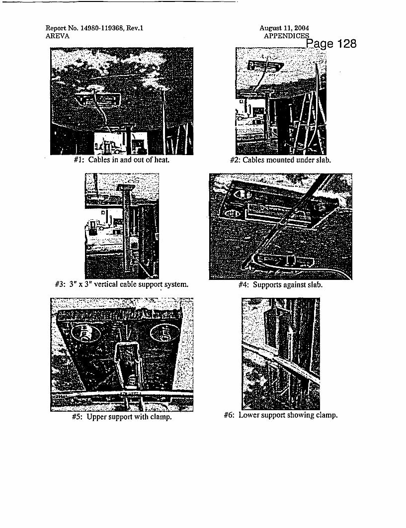
Report No. 14980-119368, Rev.1AREVA
128
#1#1: Cables in and out of heat. #2: Cables mounted under slab.
; .t ;- ,1 , .R- *_* -;;, I _-;-l[l < S nH .1.
1, "7- --P� lwi�-. T. 0 1
#3: 3" x 3" vertical cable support system. #4: Supports against slab.
-1_,-.- i, ipbjW ,> o5 ;
#5: Upper support with clamp. #6: Lower support showing clamp.

Report No. 14980-119368, Rev.1AREVA
August 11, 2004APPENDICES
Page 129
#7: Lower support showing clamp & spring.
#10: Loading test article on furnace.A: Under side of slab.
- , i.
#12: Cable ends tor megger testing.

Report No. 14980-119368, Rev.1AREVA
August 11, 2004APPENDICES
p 1-30
L -,T m.#14: Meggering the cable conductors.
#15: Specimen immediately alter tire test.

Report No. 14980-119368, Rev.1AREVA
X,-Y -777 * S 7 ;V t w ; . l-iA
August 11, 2004APPENDICES
~ ~~jageJ131
#19: Vertical support after hose stream.
#21: Upper support after hose stream. #22: Upper support after nose stream.

Report No. 14980-119368, Rev.1AREVA
August 11, 2004APPENDICES
ID le 132
#23: Spring clamp on upper support remains intact.