(astm a 126, class b) (astm b 62, c83600) style bd 150 ... · 1 body cast iron (astm a126, class b)...
TRANSCRIPT

07/11
KECKLEY COMPANY 3400 Cleveland Street Skokie, Illinois 60076 1-800-KECKLEY B1
Iron Body (ASTM A 126, CLASS B)
Style D 250# Threaded ½” – 2” .................................... 2 Style DV 250# Threaded ½” – 2” ................................. 2 Technical Data ............................................................... 3
Style KT-7 125# Threaded ⅜” – 3” ............................... 4 Technical Data ............................................................... 5 Style D 125# Flange 2” – 12” ........................................ 6 Style D 250# Flange 2” – 12” ........................................ 6 Style DV 125# Flange 2” – 12” ..................................... 6 Style DV 250# Flange 2” – 12” ..................................... 6 Technical Data ............................................................... 7
Style GFV 125# Flange 2” – 16” .................................. 8 Style GFV 250# Flange 2” – 6” .................................... 8 Technical Data ............................................................... 9
Style HLC 125# Flange 2” – 16” ................................ 10 Technical Data ............................................................. 11
Ductile Iron Body (ASTM A 536, GRADE 65-45-12)
Style KF-7 150# Flange 1½” – 12” ............................. 12 Technical Data ............................................................. 13
Bronze Body (ASTM B 62, C83600)
Style BGFV 150# Flange 1-1/2” – 12” ....................... 14 Style BGFV 300# Flange 1-1/2” – 12” ....................... 14
Technical Data ............................................................ 15
Bronze Body (Continued) (ASTM B 62, C83600)
Style BD 150# Flange 2” – 12” ...................................... 16 Style BD 300# Flange 2” – 12” ...................................... 16 Style BDV 150# Flange 2” – 12” ................................... 16 Style BDV 300# Flange 2” – 12” ................................... 16 Technical Data ................................................................ 17
Nickel Aluminum Bronze Body (ASTM B 148, C95800)
Style BKF-7 150# Flange 1½” – 12” .............................. 18 Technical Data ................................................................ 19
Carbon Steel Body (ASTM A 216, GRADE WCB)
Style SD 300# Threaded ⅜” – 3” ................................... 20 Style SD-K 150# Threaded ⅜” – 3” ............................... 20 Technical Data ................................................................ 21
Style SGFV 150# Flange 2” – 14” .................................. 22 Style SGFV-K 150# Flange 2” – 14” ............................. 22 Style SGFV 300# Flange 2” – 14” .................................. 22 Technical Data ................................................................ 23
316 Stainless Steel Body (ASTM A 351, GRADE CF8M)
Style SSD 300# Threaded ⅜” – 3” ................................. 24 Style SSD-K 150# Threaded ⅜” – 3” ............................. 24 Technical Data ................................................................ 25
Style SSGFV 150# Flange 2” – 14” ............................... 26 Style SSGFV-K 150# Flange 2” – 14” ........................... 26 Style SSGFV 300# Flange 2” – 14” ............................... 26 Technical Data ................................................................ 27
Pressure Drop Charts
Styles D, DV, BD, BDV, SD, SD-K, SSD, and SSD-K .......................................28 Styles GFV, HLC, BGFV, SGFV, SGFV-K, SSGFV, and SSGFV-K .................29 Styles BKF-7, and KF-7 ........................................................................................30 Styles KT-7 ...........................................................................................................31
Basket Strainers
KECKLEY
01/06
B2 KECKLEY COMPANY 3400 Cleveland Street Skokie, Illinois 60076 1-800-KECKLEY
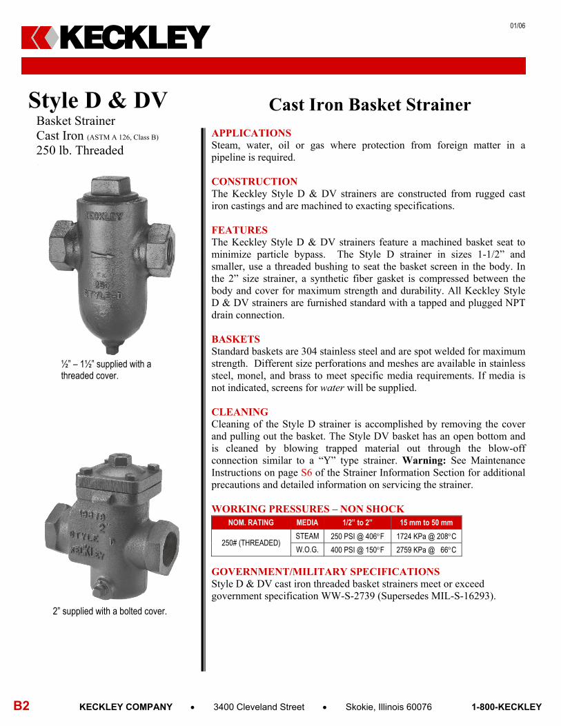
Cast Iron Basket Strainer APPLICATIONS Steam, water, oil or gas where protection from foreign matter in a pipeline is required.
CONSTRUCTION The Keckley Style D & DV strainers are constructed from rugged cast iron castings and are machined to exacting specifications. FEATURES The Keckley Style D & DV strainers feature a machined basket seat to minimize particle bypass. The Style D strainer in sizes 1-1/2” and smaller, use a threaded bushing to seat the basket screen in the body. In the 2” size strainer, a synthetic fiber gasket is compressed between the body and cover for maximum strength and durability. All Keckley Style D & DV strainers are furnished standard with a tapped and plugged NPT drain connection. BASKETS Standard baskets are 304 stainless steel and are spot welded for maximum strength. Different size perforations and meshes are available in stainless steel, monel, and brass to meet specific media requirements. If media is not indicated, screens for water will be supplied. CLEANING Cleaning of the Style D strainer is accomplished by removing the cover and pulling out the basket. The Style DV basket has an open bottom and is cleaned by blowing trapped material out through the blow-off connection similar to a “Y” type strainer. Warning: See Maintenance Instructions on page S6 of the Strainer Information Section for additional precautions and detailed information on servicing the strainer. WORKING PRESSURES – NON SHOCK
GOVERNMENT/MILITARY SPECIFICATIONS Style D & DV cast iron threaded basket strainers meet or exceed government specification WW-S-2739 (Supersedes MIL-S-16293).
NOM. RATING MEDIA 1/2” to 2” 15 mm to 50 mm
250# (THREADED) STEAM 250 PSI @ 406F 1724 KPa @ 208C
W.O.G. 400 PSI @ 150F 2759 KPa @ 66C
KECKLEY
Style D & DV Basket Strainer Cast Iron (ASTM A 126, Class B)
250 lb. Threaded
2” supplied with a bolted cover.
½” – 1½” supplied with a threaded cover.

02/08
KECKLEY COMPANY 3400 Cleveland Street Skokie, Illinois 60076 1-800-KECKLEY B3
Style D & DV Basket Strainer, 250 lb. Threaded Cast Iron (ASTM A 126, Class B)
PARTS LIST
ITEM DESCRIPTION MATERIAL
1 BODY CAST IRON (ASTM A 126, CLASS B) 2 COVER CAP* MALLEABLE IRON 3 BASKET STAINLESS STEEL (304) 4 PIPE PLUG CAST IRON
*2” SIZE HAS A BOLTED CAP WITH GASKET.
STANDARD SCREENS SUPPLIED
SIZE SCREEN
GAGE
SCREEN PERFORATION FOR STEAM OPEN
AREA FOR LIQUID OPEN
AREA in mm in mm in mm 1/2 to 2 15 to 50 28 1/32 0.8 29% 3/64 1.2 33%
Standard screens supplied are for liquid service, unless otherwise specified. Options: Other perforations, meshes, and screen materials are available.
SIZE DIMENSIONS
WEIGHTS A B C E
in mm in mm in mm in mm in mm lbs kgs 1/2 15 5-1/8 130 4-5/8 118 2-13/16 71 3/8 10 6 3 3/4 20 5-1/8 130 4-5/8 118 2-13/16 71 3/8 10 6 3 1 25 5-1/8 130 4-5/8 118 2-13/16 71 3/8 10 6 3
1-1/4 32 6-1/2 165 6-7/16 164 2-3/4 70 3/8 10 16 7 1-1/2 40 6-1/2 165 6-7/16 164 2-3/4 70 3/8 10 16 7
2 50 8-3/4 222 3-15/16 100 5-1/4 133 1/2 15 20 9 Certified dimensional drawings are available upon request. †This table reflects only the nearest metric equivalents.
FLOW COEFFICIENTS Size Cv Size Cv Size Cv 1/2" 19.9 1” 19.9 1-1/2” 35.4 3/4" 19.9 1-1/4” 35.4 2” 55.7
TOTAL SCREEN AREA Size (in2) Size (in2) Size (in2) 1/2" 20.26 1” 20.26 1-1/2” 34.91 3/4" 20.26 1-1/4” 34.91 2” 39.45
*See DETERMINING RATIOS on page S5 of the Strainer Information Section for calculating NET FREE AREA of the screen to inside pipe area.
TECHNICAL DATA DIMENSIONS AND WEIGHTS
PRESSURE vs. TEMPERATURE CHART250# Threaded Cast Iron (ASTM A 126, Class B)
0 100 200 300 400 500
Temperature [°F]
0
100
200
300
400
500
250# ClassMaximum Pressure
and Temperature Limits250 PSI at 406F400 PSI at 150F
690
1379
2069
2759
3449
Temperature [ ]°C
38 93 149 204
Pre
ssu
re [
PS
I]
260
Pre
ssure [K
Pa
]
*In Accordance with ASME B16.4
KECKLEY
05/10
B4 KECKLEY COMPANY 3400 Cleveland Street Skokie, Illinois 60076 1-800-KECKLEY
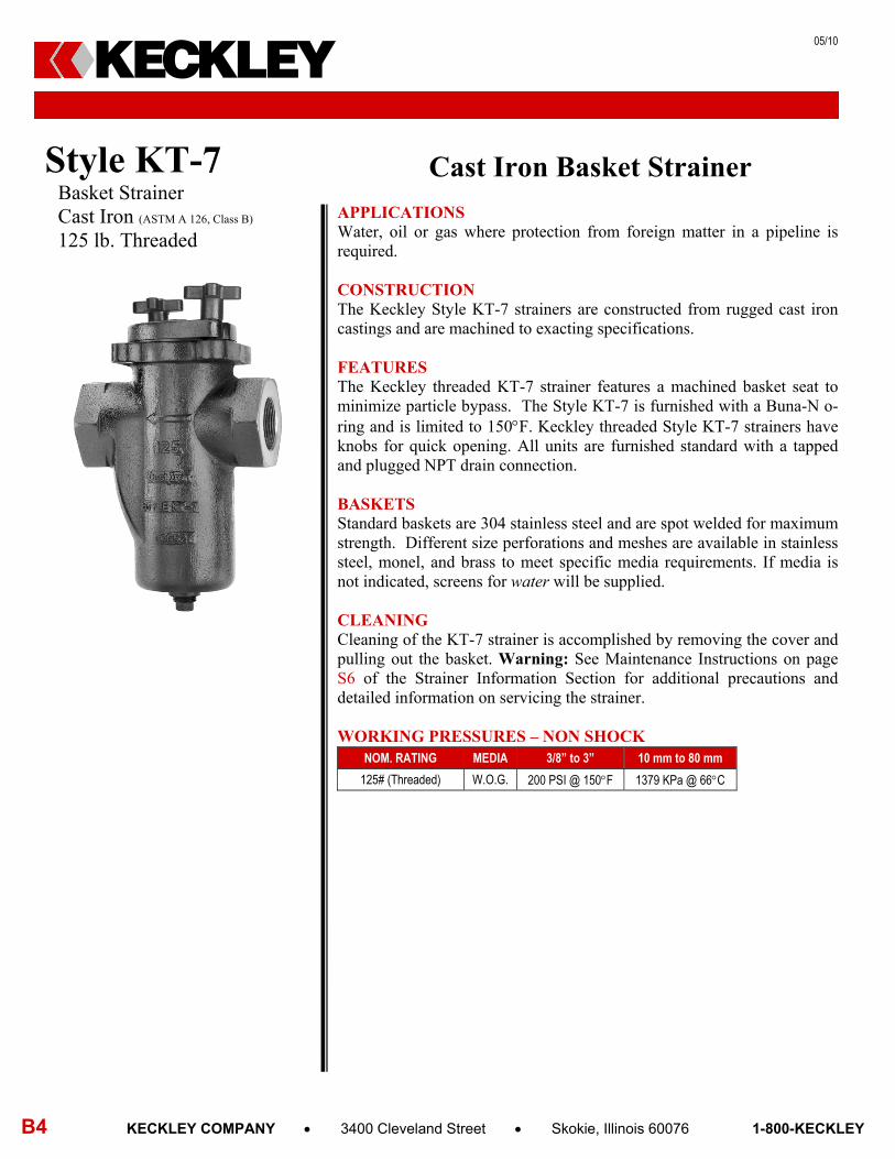
Cast Iron Basket Strainer APPLICATIONS Water, oil or gas where protection from foreign matter in a pipeline is required.
CONSTRUCTION The Keckley Style KT-7 strainers are constructed from rugged cast iron castings and are machined to exacting specifications. FEATURES The Keckley threaded KT-7 strainer features a machined basket seat to minimize particle bypass. The Style KT-7 is furnished with a Buna-N o-ring and is limited to 150F. Keckley threaded Style KT-7 strainers have knobs for quick opening. All units are furnished standard with a tapped and plugged NPT drain connection. BASKETS Standard baskets are 304 stainless steel and are spot welded for maximum strength. Different size perforations and meshes are available in stainless steel, monel, and brass to meet specific media requirements. If media is not indicated, screens for water will be supplied. CLEANING Cleaning of the KT-7 strainer is accomplished by removing the cover and pulling out the basket. Warning: See Maintenance Instructions on page S6 of the Strainer Information Section for additional precautions and detailed information on servicing the strainer. WORKING PRESSURES – NON SHOCK NOM. RATING MEDIA 3/8” to 3” 10 mm to 80 mm
125# (Threaded) W.O.G. 200 PSI @ 150F 1379 KPa @ 66C
Style KT-7 Basket Strainer Cast Iron (ASTM A 126, Class B)
125 lb. Threaded
KECKLEY

05/10
KECKLEY COMPANY 3400 Cleveland Street Skokie, Illinois 60076 1-800-KECKLEY B5
Style KT-7 Basket Strainer, 125 lb. Threaded Cast Iron (ASTM A 126, Class B)
PARTS LIST
ITEM DESCRIPTION MATERIAL
1 BODY CAST IRON (ASTM A126, CLASS B) 2 BASKET STAINLESS STEEL (304) 3 O-RING BUNA-N (MAX TEMPERATURE 150F) 4 COVER CAST IRON (ASTM A126, CLASS B) 5 STUDS CARBON STEEL (ASTM A 193, GRADE B7) 6 KNOBS CAST IRON (ASTM A126, CLASS B) 7 PLUG CAST IRON (ASTM A126, CLASS B)
STANDARD SCREENS SUPPLIED
SIZE SCREEN
GAGE
SCREEN PERFORATION FOR LIQUID OPEN
AREA in mm in mm 3/8 to 3 10 to 80 28 1/16 1.6 30%
Standard screens supplied are for liquid service, unless otherwise specified. Options: Other perforations, meshes, and screen materials are available.
SIZE DIMENSIONS
WEIGHTS A B C E
in mm in mm in mm in mm in mm lbs kgs 3/8 10 4-9/16 116 4 102 3-1/8 79 3/8 10 8 4 1/2 15 4-9/16 116 4 102 3-1/8 79 3/8 10 8 4 3/4 20 4-9/16 116 4 102 3-1/8 79 3/8 10 8 4 1 25 5-5/16 135 4-7/8 124 3 76 3/8 10 10 5
1-1/4 32 6-5/16 160 6-1/2 165 4-1/8 105 1/2 15 17 8 1-1/2 40 6-5/16 160 6-1/2 165 4-1/8 105 1/2 15 17 8
2 50 8-1/4 210 7-7/8 200 4-3/4 121 3/4 20 30 14 2-1/2 65 9-5/8 245 8-3/4 222 4 102 1 25 34 15
3 80 11-1/4 286 11-3/8 289 5-7/8 149 1 25 42 19 Certified dimensional drawings are available upon request. †This table reflects only the nearest metric equivalents.
FLOW COEFFICIENTS Size Cv Size Cv Size Cv 3/8" 15 1” 24 2” 70 1/2" 15 1-1/4” 44 2-1/2” 121 3/4" 15 1-1/2” 44 3” 158
TOTAL SCREEN AREA Size (in2) Size (in2) Size (in2) 3/8" 12.56 1” 20.17 2” 67.75 1/2" 12.56 1-1/4” 40.23 2-1/2” 75.57 3/4" 12.56 1-1/2” 40.23 3” 132.89
*See DETERMINING RATIOS on page S5 of the Strainer Information Section for calculating NET FREE AREA of the screen to inside pipe area.
TECHNICAL DATA DIMENSIONS AND WEIGHTS
KECKLEY

01/06
B6 KECKLEY COMPANY 3400 Cleveland Street Skokie, Illinois 60076 1-800-KECKLEY
Cast Iron Basket Strainer APPLICATIONS Steam, water, oil or gas where protection from foreign matter in a pipeline is required.
CONSTRUCTION The Keckley Style D & DV strainers are constructed from rugged cast iron castings and are machined to exacting specifications. These bodies have drilled flanges that are in accordance with ASME B16.1. FEATURES The Keckley Style D & DV strainers feature a machined basket seat to minimize particle bypass. All sizes have a bolted top cover flange for ease in basket removal. The gasket is a synthetic fiber and is compressed between the body and cover for maximum strength and durability. All Keckley Style D & DV strainers are furnished standard with a tapped and plugged NPT drain connection. BASKETS Standard baskets are 304 stainless steel and are spot welded for maximum strength. Different size perforations and meshes are available in stainless steel, monel, and brass to meet specific media requirements. If media is not indicated, screens for water will be supplied. CLEANING Cleaning of the Style D strainer is accomplished by removing the cover and pulling out the basket. The Style DV basket has an open bottom and is cleaned by blowing trapped material out through the blow-off connection similar to a “Y” type strainer. Warning: See Maintenance Instructions on page S6 of the Strainer Information Section for additional precautions and detailed information on servicing the strainer. WORKING PRESSURES – NON SHOCK
GOVERNMENT/MILITARY SPECIFICATIONS Style D & DV cast iron flanged basket strainers meet or exceed government specification WW-S-2739 (Supersedes MIL-S-16293).
NOM. RATING MEDIA 2” to 12” 50 mm to 300 mm
125# F.F.& D. (STANDARD FLANGE)
STEAM 125 PSI @ 450F 862 KPa @ 232C
W.O.G. 200 PSI @ 150F 1379 KPa @ 66C
NOM. RATING MEDIA 2” to 12” 50 mm to 300 mm
250# R.F.& D. (EX. HEAVY FLANGE)
STEAM 250 PSI @ 450F 1724 KPa @ 232C
W.O.G. 500 PSI @ 150F 3449 KPa @ 66C
Style D & DV Basket Strainer Cast Iron (ASTM A 126, Class B)
125 lb. & 250 lb. Flanged
KECKLEY
01/06
KECKLEY COMPANY 3400 Cleveland Street Skokie, Illinois 60076 1-800-KECKLEY B7
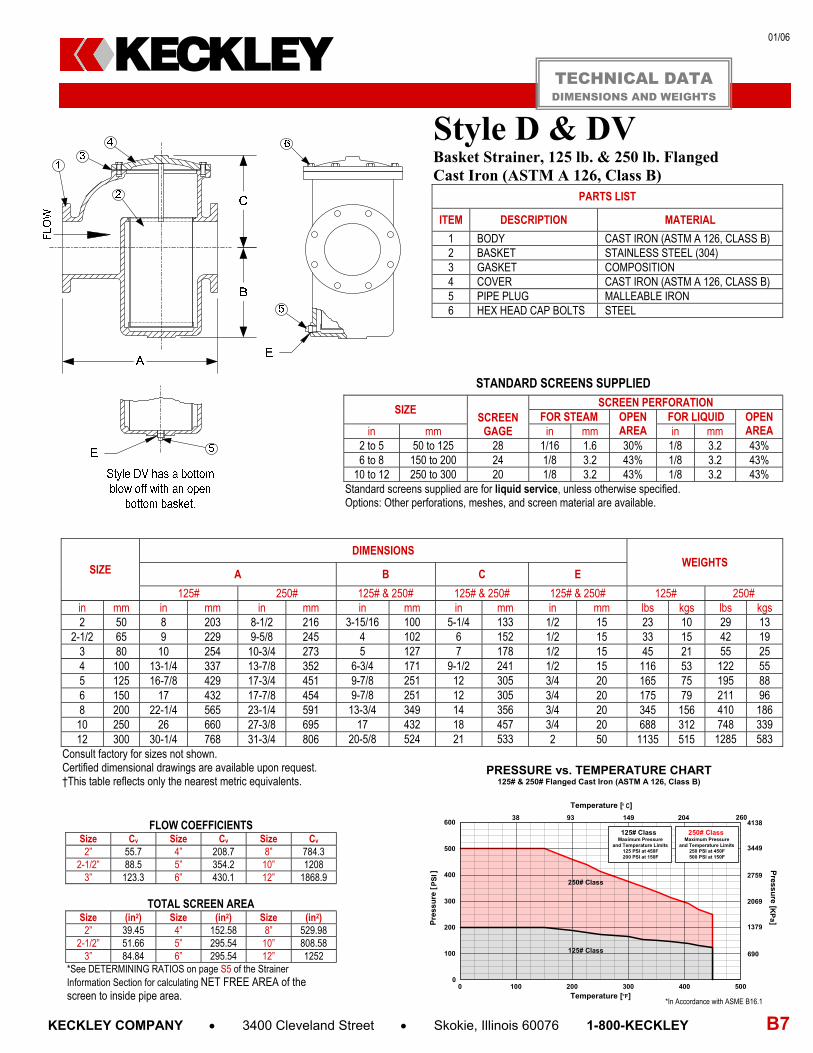
Style D & DV Basket Strainer, 125 lb. & 250 lb. Flanged Cast Iron (ASTM A 126, Class B)
PARTS LIST
ITEM DESCRIPTION MATERIAL
1 BODY CAST IRON (ASTM A 126, CLASS B) 2 BASKET STAINLESS STEEL (304) 3 GASKET COMPOSITION 4 COVER CAST IRON (ASTM A 126, CLASS B) 5 PIPE PLUG MALLEABLE IRON 6 HEX HEAD CAP BOLTS STEEL
STANDARD SCREENS SUPPLIED
SIZE SCREEN
GAGE
SCREEN PERFORATION FOR STEAM OPEN
AREA FOR LIQUID OPEN
AREA in mm in mm in mm 2 to 5 50 to 125 28 1/16 1.6 30% 1/8 3.2 43% 6 to 8 150 to 200 24 1/8 3.2 43% 1/8 3.2 43%
10 to 12 250 to 300 20 1/8 3.2 43% 1/8 3.2 43% Standard screens supplied are for liquid service, unless otherwise specified. Options: Other perforations, meshes, and screen material are available.
SIZE
DIMENSIONS WEIGHTS
A B C E
125# 250# 125# & 250# 125# & 250# 125# & 250# 125# 250# in mm in mm in mm in mm in mm in mm lbs kgs lbs kgs 2 50 8 203 8-1/2 216 3-15/16 100 5-1/4 133 1/2 15 23 10 29 13
2-1/2 65 9 229 9-5/8 245 4 102 6 152 1/2 15 33 15 42 19 3 80 10 254 10-3/4 273 5 127 7 178 1/2 15 45 21 55 25 4 100 13-1/4 337 13-7/8 352 6-3/4 171 9-1/2 241 1/2 15 116 53 122 55 5 125 16-7/8 429 17-3/4 451 9-7/8 251 12 305 3/4 20 165 75 195 88 6 150 17 432 17-7/8 454 9-7/8 251 12 305 3/4 20 175 79 211 96 8 200 22-1/4 565 23-1/4 591 13-3/4 349 14 356 3/4 20 345 156 410 186 10 250 26 660 27-3/8 695 17 432 18 457 3/4 20 688 312 748 339 12 300 30-1/4 768 31-3/4 806 20-5/8 524 21 533 2 50 1135 515 1285 583
Consult factory for sizes not shown. Certified dimensional drawings are available upon request. †This table reflects only the nearest metric equivalents.
FLOW COEFFICIENTS Size Cv Size Cv Size Cv
2” 55.7 4” 208.7 8” 784.3 2-1/2” 88.5 5” 354.2 10” 1208
3” 123.3 6” 430.1 12” 1868.9
TOTAL SCREEN AREA Size (in2) Size (in2) Size (in2)
2” 39.45 4” 152.58 8” 529.98 2-1/2” 51.66 5” 295.54 10” 808.58
3” 84.84 6” 295.54 12” 1252 *See DETERMINING RATIOS on page S5 of the Strainer Information Section for calculating NET FREE AREA of the screen to inside pipe area.
TECHNICAL DATA DIMENSIONS AND WEIGHTS
PRESSURE vs. TEMPERATURE CHART 125# & 250# Flanged Cast Iron (ASTM A 126, Class B)
125# Class
250# Class
0 100 200 300 400 500
Temperature [°F]
0
100
200
300
400
500
600
125# ClassMaximum Pressure
and Temperature Limits125 PSI at 450F200 PSI at 150F
250# ClassMaximum Pressure
and Temperature Limits250 PSI at 450F500 PSI at 150F
93 204
2069
1379
Pre
ssu
re [
PS
I]
3449
2759
690
4138
CTemperature [ ]
38 149 260
Pressu
re [KP
a ]
*In Accordance with ASME B16.1
KECKLEY

01/06
B8 KECKLEY COMPANY 3400 Cleveland Street Skokie, Illinois 60076 1-800-KECKLEY
Cast Iron Basket Strainer APPLICATIONS Steam, water, oil or gas where protection from foreign matter in a pipeline is required. CONSTRUCTION The Keckley Style GFV strainers are constructed from rugged cast iron castings and are machined to exacting specifications. These bodies have drilled flanges that are in accordance with ASME B16.1. FEATURES The Keckley Style GFV strainer features a basket with an angular cutaway design to allow straight through flow and extremely low pressure loss. All sizes have a bolted top cover flange for ease in basket removal. The gasket is a synthetic fiber and is compressed between the body and cover for maximum strength and durability. Keckley Style GFV strainers are furnished standard with a tapped and plugged NPT drain connection. BASKETS Standard baskets are 304 stainless steel and are spot welded for maximum strength. Different size perforations and meshes are available in stainless steel, monel, and brass to meet specific media requirements. If media is not indicated, screens for water will be supplied. CLEANING Cleaning of the Style GFV strainer is accomplished by removing the cover and pulling out the basket. Warning: See Maintenance Instructions on page S6 of the Strainer Information Section for additional precautions and detailed information on servicing the strainer. WORKING PRESSURES – NON SHOCK
GOVERNMENT/MILITARY SPECIFICATIONS Style GFV cast iron flanged basket strainers meet or exceed government specification WW-S-2739 (Supersedes MIL-S-16293).
NOM. RATING MEDIA 2” to 12” 50 mm to 300 mm
125# F.F.& D.
(STANDARD FLANGE)
STEAM 125 PSI @ 450F 862 KPa @ 232C W.O.G. 200 PSI @ 150F 1379 KPa @ 66C MEDIA 14” and UP 350 mm and UP STEAM 100 PSI @ 353F 690 KPa @ 178C W.O.G. 150 PSI @ 150F 1035 KPa @ 66C
NOM. RATING MEDIA 2” to 6” 50 mm to 150 mm
250# R.F.& D. (EX. HEAVY FLANGE)
STEAM 250 PSI @ 450F 1724 KPa @ 232C
W.O.G. 500 PSI @ 150F 3449 KPa @ 66C
Style GFV Basket Strainer Cast Iron (ASTM A 126, Class B)
125 lb. & 250 lb. Flanged
KECKLEY

10/08
KECKLEY COMPANY 3400 Cleveland Street Skokie, Illinois 60076 1-800-KECKLEY B9
Style GFV Basket Strainer, 125 lb. & 250 lb. Flanged Cast Iron (ASTM A 126, Class B)
PARTS LIST
ITEM DESCRIPTION MATERIAL
1 BODY CAST IRON (ASTM A 126, CLASS B) 2 BASKET STAINLESS STEEL (304) 3 GASKET COMPOSITION 4 COVER CAST IRON (ASTM A 126, CLASS B) 5 PIPE PLUG MALLEABLE IRON 6 HEX HEAD CAP SCREWS STEEL
STANDARD SCREENS SUPPLIED
SIZE SCREEN
GAGE
SCREEN PERFORATION FOR STEAM OPEN
AREA FOR LIQUID OPEN
AREA in mm in mm in mm 2 to 3 50 to 80 28 1/16 1.6 30% 1/8 3.2 43% 4 to 16 100 to 400 24 - 20 1/8 3.2 43% 1/8 3.2 43%
Standard screens supplied are for liquid service, unless otherwise specified. Options: Other perforations, meshes, and screen material are available.
SIZE
DIMENSIONS
A B C E
125# 250# 125# 250# 125# 250# 125# 250# in mm in mm in mm in mm in mm in mm in mm in mm in mm 2 50 8 203 8-1/2 216 6 152 3-7/8 98 3-1/2 89 5-1/4 133 3/4 20 1/2 15
2-1/2 65 8-1/4 210 9-1/4 235 7 178 5-3/4 146 3-3/4 95 5-1/4 133 3/4 20 3/4 20 3 80 9-3/4 248 9-1/2 241 8-1/4 210 5-3/4 146 4-1/4 108 5-1/4 133 3/4 20 3/4 20 4 100 11-1/2 292 11-13/16 300 9 229 8-9/16 217 4-3/4 121 6 152 1 25 1 25 5 125 13-1/8 333 15-3/8 391 9-3/4 248 10-1/2 267 6 152 7-3/4 197 1 25 1 25 6 150 14-3/4 375 15-1/2 394 10-1/2 267 10-1/2 267 6-1/4 159 7-3/4 197 1 25 1 25 8 200 18-1/2 470
See Style D 250 lb.
12-3/4 324 See
Style D 250 lb.
9 229 See
Style D 250 lb.
1-1/2 40 See
Style D 250 lb. 10 250 20-1/8 511 14-3/4 375 10-3/4 273 1-1/2 40 12 300 26-1/4 667 17-1/2 445 13-1/2 343 2 50 14 350 30-1/4 768 Consult
Factory 23-1/4 591 Consult
Factory 14-1/4 362 Consult
Factory 3 80 Consult
Factory 16 400 33-1/8 841 24-1/4 616 15 381 3 80 Consult factory for sizes not shown. Certified dimensional drawings are available upon request. †This table reflects only the nearest metric equivalents.
WEIGHTS Size 2” 2-1/2” 3” 4” 5” 6” 8” 10” 12” 14” 16”
125 lbs 23 33 44 67 88 120 220 353 523 814 1041 kgs 10 15 20 30 40 54 100 160 237 369 472
250 lbs 29 53 65 107 187 224
See Style D 250 lb. kgs 13 24 29 49 85 102
FLOW COEFFICIENTS Size Cv Size Cv Size Cv Size Cv
2” 42.7 4” 276.7 8” 1486.3 14” 7984.8 2 ½” 77.5 5” 442.7 10” 3051.6 16” 9565.9
3” 120.2 6” 743.1 12” 4980.6
TOTAL SCREEN AREA Size (in2) Size (in2) Size (in2) Size (in2)
2” 29.27 4” 108.44 8” 310.03 14” 1141.87 2 ½” 45.11 5” 142.29 10” 457.06 16” 1428.51
3” 78.20 6” 176.75 12” 691.07 *See DETERMINING RATIOS on page S5 of the Strainer Information Section for calculating NET FREE AREA of the screen to inside pipe area.
TECHNICAL DATA DIMENSIONS AND WEIGHTS
PRESSURE vs. TEMPERATURE CHART125# & 250# Flanged Cast Iron (ASTM A 126, Class B)
Suitable for use with pipe sizes up to 12”
125# Class
250# Class
0 100 200 300 400 500
Temperature [°F]
0
100
200
300
400
500
600
125# ClassMaximum Pressure
and Temperature Limits125 PSI at 450F200 PSI at 150F
250# ClassMaximum Pressure
and Temperature Limits250 PSI at 450F500 PSI at 150F
93 204
2069
1379
Pre
ssu
re [
PS
I]
3449
2759
690
4138
CTemperature [ ]
38 149 260
Pressu
re [KP
a ]
*In Accordance with ASME B16.1
KECKLEY
01/06
B10 KECKLEY COMPANY 3400 Cleveland Street Skokie, Illinois 60076 1-800-KECKLEY
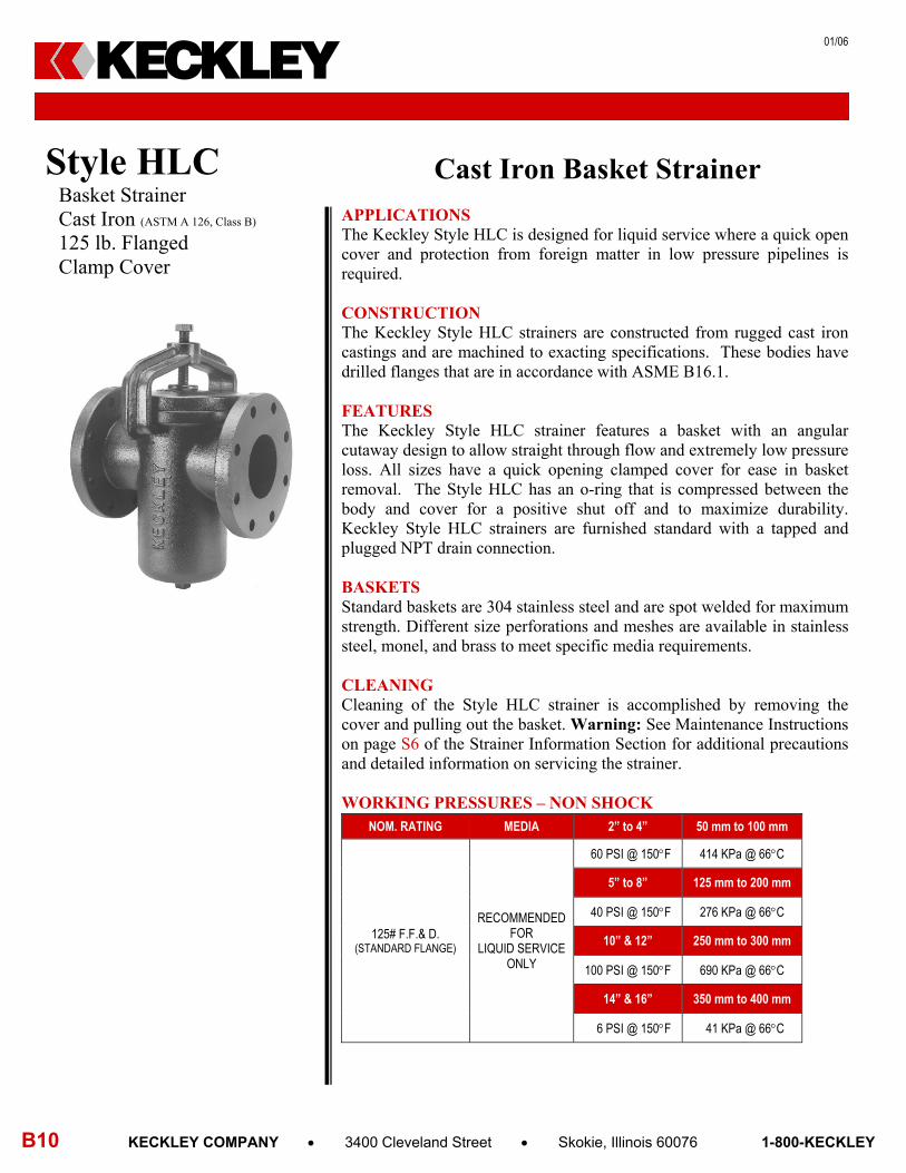
Cast Iron Basket Strainer APPLICATIONS The Keckley Style HLC is designed for liquid service where a quick open cover and protection from foreign matter in low pressure pipelines is required. CONSTRUCTION The Keckley Style HLC strainers are constructed from rugged cast iron castings and are machined to exacting specifications. These bodies have drilled flanges that are in accordance with ASME B16.1. FEATURES The Keckley Style HLC strainer features a basket with an angular cutaway design to allow straight through flow and extremely low pressure loss. All sizes have a quick opening clamped cover for ease in basket removal. The Style HLC has an o-ring that is compressed between the body and cover for a positive shut off and to maximize durability. Keckley Style HLC strainers are furnished standard with a tapped and plugged NPT drain connection. BASKETS Standard baskets are 304 stainless steel and are spot welded for maximum strength. Different size perforations and meshes are available in stainless steel, monel, and brass to meet specific media requirements. CLEANING Cleaning of the Style HLC strainer is accomplished by removing the cover and pulling out the basket. Warning: See Maintenance Instructions on page S6 of the Strainer Information Section for additional precautions and detailed information on servicing the strainer.
WORKING PRESSURES – NON SHOCK
NOM. RATING MEDIA 2” to 4” 50 mm to 100 mm
125# F.F.& D.
(STANDARD FLANGE)
RECOMMENDED FOR
LIQUID SERVICE ONLY
60 PSI @ 150F 414 KPa @ 66C
5” to 8” 125 mm to 200 mm
40 PSI @ 150F 276 KPa @ 66C
10” & 12” 250 mm to 300 mm
100 PSI @ 150F 690 KPa @ 66C
14” & 16” 350 mm to 400 mm
6 PSI @ 150F 41 KPa @ 66C
Style HLC Basket Strainer Cast Iron (ASTM A 126, Class B)
125 lb. Flanged Clamp Cover
KECKLEY

01/06
KECKLEY COMPANY 3400 Cleveland Street Skokie, Illinois 60076 1-800-KECKLEY B11
Style HLC Basket Strainer, 125 lb. Flanged Cast Iron (ASTM A 126, Class B)
PARTS LIST
ITEM DESCRIPTION MATERIAL
1 BODY CAST IRON (ASTM A 126, CLASS B) 2 BASKET STAINLESS STEEL (304) 3 O-RING BUNA-N 4 COVER CAST IRON (ASTM A 126, CLASS B) 5 PIPE PLUG MALLEABLE IRON 6 CLAMP CAST IRON (ASTM A 126, CLASS B) 7 CLAMP SCREW CARBON STEEL (ASTM A 193, GRADE B7)
STANDARD SCREENS SUPPLIED
SIZE SCREEN
GAGE
SCREEN PERFORATION FOR LIQUID OPEN
AREA in mm in mm 2 to 3 50 to 80 28 3/64 1.2 33% 4 to 16 100 to 400 24 - 20 1/8 3.2 43%
Options: Other perforations, meshes, and screen materials are available.
SIZE DIMENSIONS
WEIGHTS A B C E
in mm in mm in mm in mm in mm lbs kgs 2 50 8 203 6 152 6-1/2 165 3/4 20 26 12
2-1/2 65 8-1/4 210 7 178 6-3/4 171 3/4 20 37 17 3 80 9-3/4 248 8-1/4 210 7-3/4 197 3/4 20 50 23 4 100 11-1/2 292 9 229 9 229 1 25 74 34 5 125 13-1/8 333 9-3/4 248 10 254 1 25 97 44 6 150 14-3/4 375 10-1/2 267 10-1/2 267 1 25 131 59 8 200 18-1/2 470 12-3/4 324 13-3/4 349 1 25 236 107
10 250 20-1/8 511 14-3/4 375 14-1/4 362 1-1/2 40 382 173 12 300 26-1/4 667 17-1/2 445 17-1/4 438 1-1/2 40 783 355 14 350 30-1/4 768 23-1/4 591 On appl. On appl. 2 50 864 392 16 400 33-1/8 841 24-1/4 616 On appl. On appl. 2 50 1106 502
Certified dimensional drawings are available upon request. †This table reflects only the nearest metric equivalents.
FLOW COEFFICIENTS Size Cv Size Cv Size Cv
2” 42.7 5” 442.7 12” 4980.6 2 ½” 77.5 6” 743.1 14” 7984.8
3” 120.2 8” 1486.3 16” 9565.9 4” 276.7 10” 3051.6
TOTAL SCREEN AREA Size (in2) Size (in2) Size (in2)
2” 29.27 5” 142.29 12” 691.07 2 ½” 45.11 6” 176.75 14” 1141.87
3” 78.20 8” 310.03 16” 1428.51 4” 108.44 10” 457.06
*See DETERMINING RATIOS on page S5 of the Strainer Information Section for calculating NET FREE AREA of the screen to inside pipe area.
Working pressure – Non shock Water service 2” to 4” …………..60 psi - 150F 5” to 8” …………..40 psi - 150F 14” to 16” ……….. 6 psi - 150F Special Double Clamp 10” to 12” ………100 psi - 150F Consult factory for higher pressure and temperature limits.
TECHNICAL DATA DIMENSIONS AND WEIGHTS
KECKLEY
12/10
B12 KECKLEY COMPANY 3400 Cleveland Street Skokie, Illinois 60076 1-800-KECKLEY
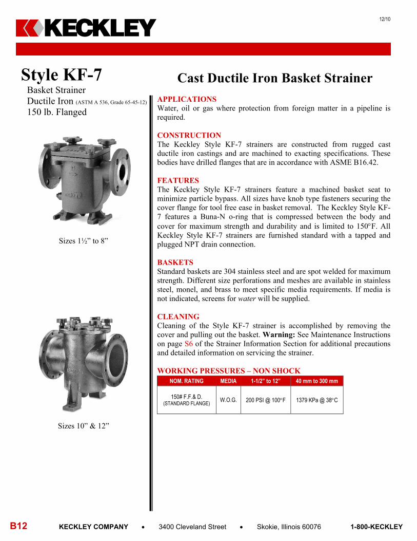
Cast Ductile Iron Basket Strainer APPLICATIONS Water, oil or gas where protection from foreign matter in a pipeline is required.
CONSTRUCTION The Keckley Style KF-7 strainers are constructed from rugged cast ductile iron castings and are machined to exacting specifications. These bodies have drilled flanges that are in accordance with ASME B16.42. FEATURES The Keckley Style KF-7 strainers feature a machined basket seat to minimize particle bypass. All sizes have knob type fasteners securing the cover flange for tool free ease in basket removal. The Keckley Style KF-7 features a Buna-N o-ring that is compressed between the body and cover for maximum strength and durability and is limited to 150F. All Keckley Style KF-7 strainers are furnished standard with a tapped and plugged NPT drain connection. BASKETS Standard baskets are 304 stainless steel and are spot welded for maximum strength. Different size perforations and meshes are available in stainless steel, monel, and brass to meet specific media requirements. If media is not indicated, screens for water will be supplied. CLEANING Cleaning of the Style KF-7 strainer is accomplished by removing the cover and pulling out the basket. Warning: See Maintenance Instructions on page S6 of the Strainer Information Section for additional precautions and detailed information on servicing the strainer. WORKING PRESSURES – NON SHOCK
NOM. RATING MEDIA 1-1/2” to 12” 40 mm to 300 mm
150# F.F.& D. (STANDARD FLANGE)
W.O.G. 200 PSI @ 100F 1379 KPa @ 38C
Style KF-7 Basket Strainer Ductile Iron (ASTM A 536, Grade 65-45-12)
150 lb. Flanged
KECKLEY
Sizes 1½” to 8”
Sizes 10” & 12”
05/10
KECKLEY COMPANY 3400 Cleveland Street Skokie, Illinois 60076 1-800-KECKLEY B13
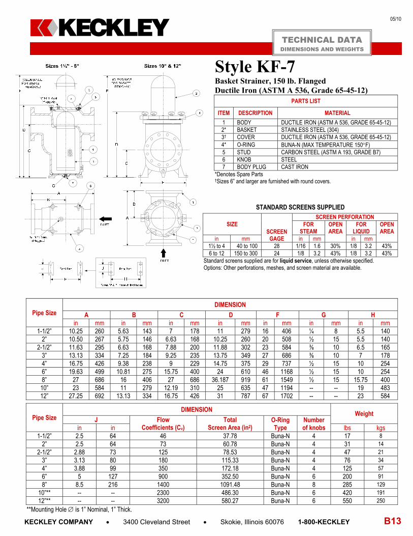
Style KF-7 Basket Strainer, 150 lb. Flanged Ductile Iron (ASTM A 536, Grade 65-45-12)
PARTS LIST
ITEM DESCRIPTION MATERIAL
1 BODY DUCTILE IRON (ASTM A 536, GRADE 65-45-12) 2* BASKET STAINLESS STEEL (304) 3† COVER DUCTILE IRON (ASTM A 536, GRADE 65-45-12) 4* O-RING BUNA-N (MAX TEMPERATURE 150F) 5 STUD CARBON STEEL (ASTM A 193, GRADE B7) 6 KNOB STEEL 7 BODY PLUG CAST IRON
*Denotes Spare Parts †Sizes 6” and larger are furnished with round covers.
STANDARD SCREENS SUPPLIED
SIZE SCREEN
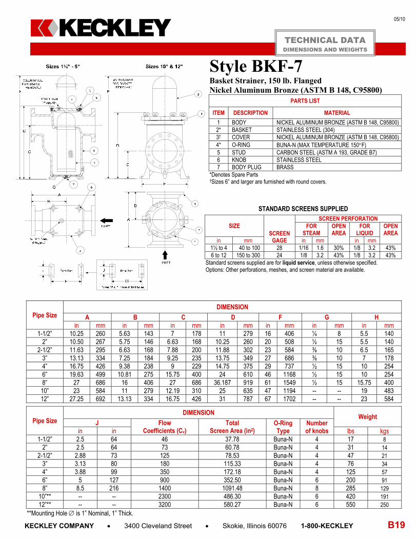
GAGE
SCREEN PERFORATION FOR
STEAM OPEN AREA
FOR LIQUID
OPEN AREA
in mm in mm in mm 1½ to 4 40 to 100 28 1/16 1.6 30% 1/8 3.2 43% 6 to 12 150 to 300 24 1/8 3.2 43% 1/8 3.2 43%
Standard screens supplied are for liquid service, unless otherwise specified. Options: Other perforations, meshes, and screen material are available.
Pipe Size DIMENSION
A B C D F G H in mm in mm in mm in mm in mm in mm in mm
1-1/2” 10.25 260 5.63 143 7 178 11 279 16 406 ¼ 8 5.5 140 2” 10.50 267 5.75 146 6.63 168 10.25 260 20 508 ½ 15 5.5 140
2-1/2” 11.63 295 6.63 168 7.88 200 11.88 302 23 584 ⅜ 10 6.5 165 3” 13.13 334 7.25 184 9.25 235 13.75 349 27 686 ⅜ 10 7 178 4” 16.75 426 9.38 238 9 229 14.75 375 29 737 ½ 15 10 254 6” 19.63 499 10.81 275 15.75 400 24 610 46 1168 ½ 15 10 254 8” 27 686 16 406 27 686 36.187 919 61 1549 ½ 15 15.75 400 10” 23 584 11 279 12.19 310 25 635 47 1194 -- -- 19 483 12” 27.25 692 13.13 334 16.75 426 31 787 67 1702 -- -- 23 584
Pipe Size DIMENSION
Weight J Flow
Coefficients (Cv) Total
Screen Area (in2) O-Ring Type
Number of knobs in in lbs kgs
1-1/2” 2.5 64 46 37.78 Buna-N 4 17 8 2” 2.5 64 73 60.78 Buna-N 4 31 14
2-1/2” 2.88 73 125 78.53 Buna-N 4 47 21 3” 3.13 80 180 115.33 Buna-N 4 76 34 4” 3.88 99 350 172.18 Buna-N 4 125 57 6” 5 127 900 352.50 Buna-N 6 200 91 8” 8.5 216 1400 1091.48 Buna-N 8 285 129
10”** -- -- 2300 486.30 Buna-N 6 420 191 12”** -- -- 3200 580.27 Buna-N 6 550 250
**Mounting Hole is 1” Nominal, 1” Thick.
TECHNICAL DATA DIMENSIONS AND WEIGHTS
KECKLEY

07/11
B14 KECKLEY COMPANY 3400 Cleveland Street Skokie, Illinois 60076 1-800-KECKLEY
Cast Bronze Basket Strainer APPLICATIONS Steam, water, oil or gas where protection from foreign matter in a pipeline is required. CONSTRUCTION The Keckley Style BGFV strainers are constructed from rugged bronze castings and are machined to exacting specifications. These bodies have drilled flanges that are in accordance with ASME B16.24. All flanges come standard with back-faced bolt holes. FEATURES The Keckley Style BGFV strainer features a basket with an angular cutaway design to allow straight through flow and extremely low pressure loss. All sizes have a bolted top cover flange for ease in basket removal. The gasket is spiral wound stainless steel and is compressed between the body and cover (for maximum strength and durability) and designed for high pressure and high temperature service. Keckley Style BGFV strainers have hex head cap screws and furnished standard with a tapped and plugged NPT drain connection. BASKETS Standard baskets are stainless steel and are spot welded for maximum strength. Different size perforations and meshes are available in stainless steel, monel, and brass to meet specific media requirements. If media is not indicated, screens for water will be supplied. CLEANING Cleaning of the Style BGFV strainer is accomplished by removing the cover and pulling out the basket. Warning: See Maintenance Instructions on page S6 of the Strainer Information Section for additional precautions and detailed information on servicing the strainer. WORKING PRESSURES – NON SHOCK
NOM. RATING MEDIA 1-1/2” to 12” 40 mm to 300 mm
150# F.F.& D. (STANDARD FLANGE)
STEAM 150 PSI @ 406F 1035 KPa @ 208C
W.O.G. 225 PSI @ 150F 1552 KPa @ 66C
NOM. RATING MEDIA 1-1/2” to 12” 40 mm to 300 mm
300# F.F.& D. (EX. HEAVY FLANGE)
STEAM 300 PSI @ 406F 2069 KPa @ 208C
W.O.G. 500 PSI @ 150F 3449 KPa @ 66C
Style BGFV
Basket Strainer Cast Bronze (ASTM B62, C83600)
150 lb. & 300 lb. Flanged
KECKLEY

07/11
KECKLEY COMPANY 3400 Cleveland Street Skokie, Illinois 60076 1-800-KECKLEY B15
5
1 6 43
2
A
B
C
E
Style BGFV Basket Strainer, 150 lb. & 300 lb. Flanged Cast Bronze (ASTM B 62, C83600)
PARTS LIST
ITEM DESCRIPTION MATERIAL 1 BODY CAST BRONZE (ASTM B 62, C83600) 2 BASKET STAINLESS STEEL (304) 3 GASKET SPIRAL WOUND STAINLESS STEEL (304) 4 COVER CAST BRONZE (ASTM B 62, C83600) 5 PIPE PLUG STAINLESS STEEL (316) 6 HEX HEAD CAP SCREW STAINLESS STEEL (316)
STANDARD SCREENS SUPPLIED
SIZE SCREEN
GAGE
SCREEN PERFORATION FOR
STEAM OPEN AREA
FOR LIQUID
OPEN AREA
in mm in mm in mm 1-1/2 to 3 40 to 80 22 3/64 1.2 33% 1/16 1.6 30%
4 to 12 100 to 300 22 1/16 1.6 30% 1/8 3.2 43% Standard screens supplied are for liquid service, unless otherwise specified. Options: Other perforations, meshes, and screen materials are available.
SIZE
DIMENSIONS
A B C E
150# 300# 150# 300# 150# 300# 150# 300# in mm in mm in mm in mm in mm in mm in mm in mm in mm
1-1/2 40 6-1/2 165 7 178 1-1/2 38 4 102 4 102 3-3/4 95 1/2 15 1/2 15 2 50 8-1/2 216 8-13/16 224 5-7/8 149 4-3/4 121 4-3/4 121 3-3/4 95 1/2 15 1 25
2-1/2 65 8 203 9 229 5-7/16 138 5-5/8 143 4-1/4 108 4-5/8 117 3/4 20 1 25 3 80 8-3/4 222 10-1/16 256 5-11/16 144 5-11/16 144 5-5/8 143 5-5/8 143 3/4 20 3/4 20 4 100 11-3/16 284 12 305 8-1/4 210 8-1/4 210 6-1/16 154 6-1/16 154 1 25 1 25 5 125 12-1/4 311 13-1/8 333 10-1/4 260 10-1/4 260 5-5/8 143 5-5/8 143 1 25 1 25 6 150 13-7/8 352 15-9/16 395 12-13/64 310 12-13/64 310 6-5/16 149 6-5/16 160 1-1/4 32 1-1/4 32 8 200 17-3/8 441 18-7/8 479 15-9/16 395 15-9/16 395 8-3/16 208 8-3/16 208 1-1/2 40 1-1/4 40
10 250 22 559 21-5/16 541 16 406 14-3/8 365 10-3/8 264 9-7/8 251 1-1/2 40 2 50 12 300 25 635 25-3/8 645 23-3/4 603 23-3/4 603 12-3/8 314 12-3/8 314 2 50 2 50
Larger sizes available upon request. Certified dimensional drawings are available upon request. †This table reflects only the nearest metric equivalents.
WEIGHTS
Size 1-1/2” 2” 2-1/2” 3” 4” 5” 6” 8” 10” 12”
150 lbs 22 30 35 39 69 110 125 270 360 450 kgs 10 14 16 18 31 50 57 122 163 204
300 Lbs 24 32 42 56 88 126 150 295 420 500 kgs 11 15 19 25 40 57 68 134 191 227
FLOW COEFFICIENTS Size Cv Size Cv Size Cv
2” 42.7 5” 442.7 10” 3051.6 3” 120.2 6” 743.1 12” 4980.6 4” 276.7 8” 1486.3
TOTAL SCREEN AREA (150 LB.) Size (in2) Size (in2) Size (in2)
2” 53.42 5” 129.0 10” 591.73 3” 54.53 6” 215.65 12” 1040.63 4” 117.94 8” 401.76
*See DETERMINING RATIOS on page S5 of the Strainer Information Section for calculating NET FREE AREA of the screen to inside pipe area.
TECHNICAL DATA DIMENSIONS AND WEIGHTS
KECKLEY
PRESSURE vs. TEMPERATURE CHART150# & 300# Flanged Cast Bronze (ASTM B 62, C83600)
150# Class
300# Class
0 100 200 300 400 5000
100
200
300
400
500
600
150# ClassMaximum Pressure
and Temperature Limits150 PSI at 406F225 PSI at 150F
300# ClassMaximum Pressure
and Temperature Limits300 PSI at 406F500 PSI at 150F
Pre
s su
r e [
PS
I]
Temperature [F]
Temperature [C]
690
1379
2069
2759
3449
413838 93 149 204 260
Pressu
re [K
Pa]

05/10
B16 KECKLEY COMPANY 3400 Cleveland Street Skokie, Illinois 60076 1-800-KECKLEY
Cast Bronze Basket Strainer APPLICATIONS Steam, water, oil or gas where protection from foreign matter in a pipeline is required. CONSTRUCTION The Keckley Style BD & BDV strainers are constructed from rugged cast bronze castings and are machined to exacting specifications. These bodies have drilled flanges that are in accordance with ASME B16.24. FEATURES The Keckley Style BD & BDV strainers feature a machined basket seat to minimize particle bypass. All sizes have a bolted top cover flange for ease in basket removal. The gasket is a synthetic fiber and is compressed between the body and cover for maximum strength and durability. All Keckley Style BD & BDV strainers are furnished standard with a tapped and plugged NPT drain connection. BASKETS Standard baskets are 304 stainless steel and are spot welded for maximum strength. Different size perforations and meshes are available in stainless steel, monel, and brass to meet specific media requirements. If media is not indicated, screens for water will be supplied. CLEANING Cleaning of the Style BD strainer is accomplished by removing the cover and pulling out the basket. The Style BDV basket has an open bottom and is cleaned by blowing trapped material out through the blow-off connection similar to a “Y” type strainer. Warning: See Maintenance Instructions on page S6 of the Strainer Information Section for additional precautions and detailed information on servicing the strainer.
WORKING PRESSURES – NON SHOCK NOM. RATING MEDIA 2” to 12” 50 mm to 300 mm
150# F.F.& D.
(STANDARD FLANGE)
STEAM 150 PSI @ 406F 1035 KPa @ 208C
W.O.G. 225 PSI @ 150F 1552 KPa @ 66C
NOM. RATING MEDIA 2” to 12” 50 mm to 300 mm
300# F.F.& D. (EX. HEAVY FLANGE)
STEAM 300 PSI @ 406F 2069 KPa @ 208C
W.O.G. 500 PSI @ 150F 3449 KPa @ 66C
Style BD & BDV Basket Strainer Cast Bronze (ASTM B 62, C83600)
150 lb. & 300 lb. Flanged
KECKLEY
05/10
KECKLEY COMPANY 3400 Cleveland Street Skokie, Illinois 60076 1-800-KECKLEY B17
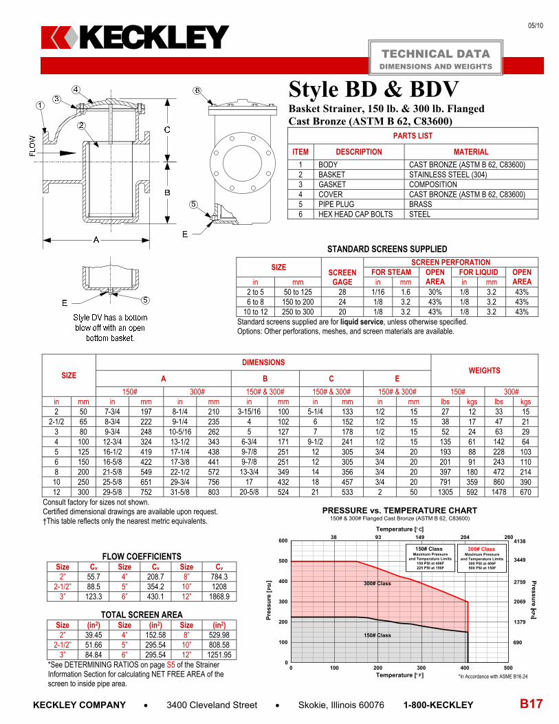
Style BD & BDV Basket Strainer, 150 lb. & 300 lb. Flanged Cast Bronze (ASTM B 62, C83600)
PARTS LIST
ITEM DESCRIPTION MATERIAL
1 BODY CAST BRONZE (ASTM B 62, C83600) 2 BASKET STAINLESS STEEL (304) 3 GASKET COMPOSITION 4 COVER CAST BRONZE (ASTM B 62, C83600) 5 PIPE PLUG BRASS 6 HEX HEAD CAP BOLTS STEEL
STANDARD SCREENS SUPPLIED
SIZE SCREEN
GAGE
SCREEN PERFORATION FOR STEAM OPEN
AREA FOR LIQUID OPEN
AREA in mm in mm in mm 2 to 5 50 to 125 28 1/16 1.6 30% 1/8 3.2 43% 6 to 8 150 to 200 24 1/8 3.2 43% 1/8 3.2 43%
10 to 12 250 to 300 20 1/8 3.2 43% 1/8 3.2 43% Standard screens supplied are for liquid service, unless otherwise specified. Options: Other perforations, meshes, and screen materials are available.
SIZE
DIMENSIONS WEIGHTS
A B C E
150# 300# 150# & 300# 150# & 300# 150# & 300# 150# 300# in mm in mm in mm in mm in mm in mm lbs kgs lbs kgs 2 50 7-3/4 197 8-1/4 210 3-15/16 100 5-1/4 133 1/2 15 27 12 33 15
2-1/2 65 8-3/4 222 9-1/4 235 4 102 6 152 1/2 15 38 17 47 21 3 80 9-3/4 248 10-5/16 262 5 127 7 178 1/2 15 52 24 63 29 4 100 12-3/4 324 13-1/2 343 6-3/4 171 9-1/2 241 1/2 15 135 61 142 64 5 125 16-1/2 419 17-1/4 438 9-7/8 251 12 305 3/4 20 193 88 228 103 6 150 16-5/8 422 17-3/8 441 9-7/8 251 12 305 3/4 20 201 91 243 110 8 200 21-5/8 549 22-1/2 572 13-3/4 349 14 356 3/4 20 397 180 472 214 10 250 25-5/8 651 29-3/4 756 17 432 18 457 3/4 20 791 359 860 390 12 300 29-5/8 752 31-5/8 803 20-5/8 524 21 533 2 50 1305 592 1478 670
Consult factory for sizes not shown. Certified dimensional drawings are available upon request. †This table reflects only the nearest metric equivalents.
FLOW COEFFICIENTS Size Cv Size Cv Size Cv
2” 55.7 4” 208.7 8” 784.3 2-1/2” 88.5 5” 354.2 10” 1208
3” 123.3 6” 430.1 12” 1868.9
TOTAL SCREEN AREA Size (in2) Size (in2) Size (in2)
2” 39.45 4” 152.58 8” 529.98 2-1/2” 51.66 5” 295.54 10” 808.58
3” 84.84 6” 295.54 12” 1251.95 *See DETERMINING RATIOS on page S5 of the Strainer Information Section for calculating NET FREE AREA of the screen to inside pipe area.
TECHNICAL DATA DIMENSIONS AND WEIGHTS
PRESSURE vs. TEMPERATURE CHART150# & 300# Flanged Cast Bronze (ASTM B 62, C83600)
150# Class
300# Class
0 100 200 300 400 5000
100
200
300
400
500
600
150# ClassMaximum Pressure
and Temperature Limits150 PSI at 406F225 PSI at 150F
300# ClassMaximum Pressure
and Temperature Limits300 PSI at 406F500 PSI at 150F
Pre
ssu
re [
PS
I]
Temperature [F]
Temperature [C]
690
1379
2069
2759
3449
413838 93 149 204 260
Press
ure [K
Pa ]
*In Accordance with ASME B16.24
KECKLEY
12/10
B18 KECKLEY COMPANY 3400 Cleveland Street Skokie, Illinois 60076 1-800-KECKLEY
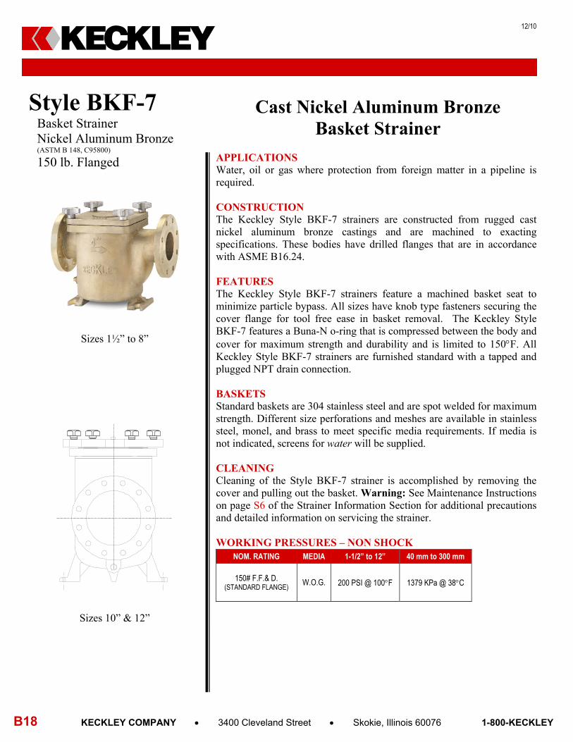
Cast Nickel Aluminum Bronze Basket Strainer
APPLICATIONS Water, oil or gas where protection from foreign matter in a pipeline is required.
CONSTRUCTION The Keckley Style BKF-7 strainers are constructed from rugged cast nickel aluminum bronze castings and are machined to exacting specifications. These bodies have drilled flanges that are in accordance with ASME B16.24. FEATURES The Keckley Style BKF-7 strainers feature a machined basket seat to minimize particle bypass. All sizes have knob type fasteners securing the cover flange for tool free ease in basket removal. The Keckley Style BKF-7 features a Buna-N o-ring that is compressed between the body and cover for maximum strength and durability and is limited to 150F. All Keckley Style BKF-7 strainers are furnished standard with a tapped and plugged NPT drain connection. BASKETS Standard baskets are 304 stainless steel and are spot welded for maximum strength. Different size perforations and meshes are available in stainless steel, monel, and brass to meet specific media requirements. If media is not indicated, screens for water will be supplied. CLEANING Cleaning of the Style BKF-7 strainer is accomplished by removing the cover and pulling out the basket. Warning: See Maintenance Instructions on page S6 of the Strainer Information Section for additional precautions and detailed information on servicing the strainer. WORKING PRESSURES – NON SHOCK
NOM. RATING MEDIA 1-1/2” to 12” 40 mm to 300 mm
150# F.F.& D. (STANDARD FLANGE)
W.O.G. 200 PSI @ 100F 1379 KPa @ 38C
Style BKF-7 Basket Strainer Nickel Aluminum Bronze (ASTM B 148, C95800)
150 lb. Flanged
KECKLEY
Sizes 1½” to 8”
Sizes 10” & 12”
05/10
KECKLEY COMPANY 3400 Cleveland Street Skokie, Illinois 60076 1-800-KECKLEY B19
Style BKF-7 Basket Strainer, 150 lb. Flanged Nickel Aluminum Bronze (ASTM B 148, C95800)
PARTS LIST
ITEM DESCRIPTION MATERIAL
1 BODY NICKEL ALUMINUM BRONZE (ASTM B 148, C95800) 2* BASKET STAINLESS STEEL (304) 3† COVER NICKEL ALUMINUM BRONZE (ASTM B 148, C95800) 4* O-RING BUNA-N (MAX TEMPERATURE 150F) 5 STUD CARBON STEEL (ASTM A 193, GRADE B7) 6 KNOB STAINLESS STEEL 7 BODY PLUG BRASS
*Denotes Spare Parts †Sizes 6” and larger are furnished with round covers.
STANDARD SCREENS SUPPLIED
SIZE SCREEN
GAGE
SCREEN PERFORATION FOR
STEAM OPEN AREA
FOR LIQUID
OPEN AREA
in mm in mm in mm 1½ to 4 40 to 100 28 1/16 1.6 30% 1/8 3.2 43% 6 to 12 150 to 300 24 1/8 3.2 43% 1/8 3.2 43%
Standard screens supplied are for liquid service, unless otherwise specified. Options: Other perforations, meshes, and screen material are available.
Pipe Size DIMENSION
A B C D F G H in mm in mm in mm in mm in mm in mm in mm
1-1/2” 10.25 260 5.63 143 7 178 11 279 16 406 ¼ 8 5.5 140 2” 10.50 267 5.75 146 6.63 168 10.25 260 20 508 ½ 15 5.5 140
2-1/2” 11.63 295 6.63 168 7.88 200 11.88 302 23 584 ⅜ 10 6.5 165 3” 13.13 334 7.25 184 9.25 235 13.75 349 27 686 ⅜ 10 7 178 4” 16.75 426 9.38 238 9 229 14.75 375 29 737 ½ 15 10 254 6” 19.63 499 10.81 275 15.75 400 24 610 46 1168 ½ 15 10 254 8” 27 686 16 406 27 686 36.187 919 61 1549 ½ 15 15.75 400 10” 23 584 11 279 12.19 310 25 635 47 1194 -- -- 19 483 12” 27.25 692 13.13 334 16.75 426 31 787 67 1702 -- -- 23 584
Pipe Size DIMENSION
Weight J Flow
Coefficients (Cv) Total
Screen Area (in2) O-Ring Type
Number of knobs in in lbs kgs
1-1/2” 2.5 64 46 37.78 Buna-N 4 17 8 2” 2.5 64 73 60.78 Buna-N 4 31 14
2-1/2” 2.88 73 125 78.53 Buna-N 4 47 21 3” 3.13 80 180 115.33 Buna-N 4 76 34 4” 3.88 99 350 172.18 Buna-N 4 125 57 6” 5 127 900 352.50 Buna-N 6 200 91 8” 8.5 216 1400 1091.48 Buna-N 8 285 129
10”** -- -- 2300 486.30 Buna-N 6 420 191 12”** -- -- 3200 580.27 Buna-N 6 550 250
**Mounting Hole is 1” Nominal, 1” Thick.
TECHNICAL DATA DIMENSIONS AND WEIGHTS
KECKLEY

05/10
B20 KECKLEY COMPANY 3400 Cleveland Street Skokie, Illinois 60076 1-800-KECKLEY
Cast Carbon Steel Basket Strainer APPLICATIONS Steam, water, oil or gas where protection from foreign matter in a pipeline is required.
CONSTRUCTION The Keckley Style SD and SD-K strainers are constructed from rugged carbon steel castings and are machined to exacting specifications. FEATURES The Keckley threaded Style SD and SD-K strainers feature a machined basket seat to minimize particle bypass. The Style SD has a spiral wound 304 stainless steel gasket and is compressed between the body and cover (for maximum strength and durability) and designed for high pressure and high temperature service. The Style SD-K is furnished with a Buna-N O-ring and is limited to 158F. Keckley threaded Style SD strainers have carbon steel hex head cap screws. All units are furnished standard with a tapped and plugged NPT drain connection. BASKETS Standard baskets are 304 stainless steel and are spot welded for maximum strength. Different size perforations and meshes are available in stainless steel, monel, and brass to meet specific media requirements. If media is not indicated, screens for water will be supplied. CLEANING Cleaning of the Style SD and SD-K strainers are accomplished by removing the cover and pulling out the basket. Warning: See Maintenance Instructions on page S6 of the Strainer Information Section for additional precautions and detailed information on servicing the strainer. WORKING PRESSURES – NON SHOCK NOM. RATING MEDIA 3/8” to 3” 10 mm to 80 mm
300# (THREADED)
BOLTED COVER STEAM 300 PSI @ 838F 2069 KPa @ 448C
W.O.G. 740 PSI @ 100F 5104 KPa @ 38C
NOM. RATING MEDIA 3/8” to 3” 10 mm to 80 mm
150# (THREADED)
KNOB TYPE COVER W.O.G. 200 PSI @ 150F 1379 KPa @ 66C
Style SD Basket Strainer Carbon Steel (ASTM A 216, Grade WCB)
300 lb. Threaded
KECKLEY
Style SD-K Basket Strainer Carbon Steel (ASTM A 216, Grade WCB)
150 lb. Threaded
05/10
KECKLEY COMPANY 3400 Cleveland Street Skokie, Illinois 60076 1-800-KECKLEY B21
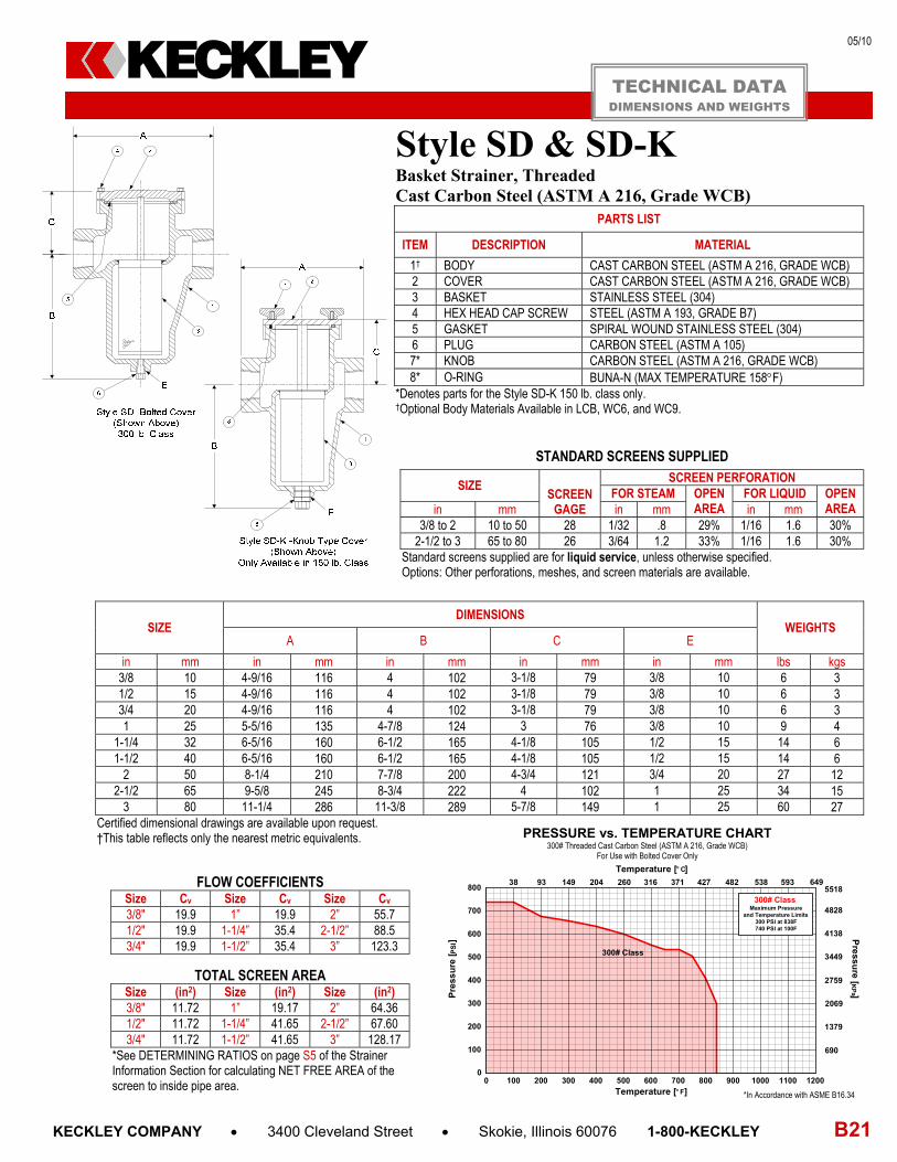
Style SD & SD-K Basket Strainer, Threaded Cast Carbon Steel (ASTM A 216, Grade WCB)
PARTS LIST
ITEM DESCRIPTION MATERIAL
1† BODY CAST CARBON STEEL (ASTM A 216, GRADE WCB) 2 COVER CAST CARBON STEEL (ASTM A 216, GRADE WCB) 3 BASKET STAINLESS STEEL (304) 4 HEX HEAD CAP SCREW STEEL (ASTM A 193, GRADE B7) 5 GASKET SPIRAL WOUND STAINLESS STEEL (304) 6 PLUG CARBON STEEL (ASTM A 105) 7* KNOB CARBON STEEL (ASTM A 216, GRADE WCB) 8* O-RING BUNA-N (MAX TEMPERATURE 158F)
*Denotes parts for the Style SD-K 150 lb. class only. †Optional Body Materials Available in LCB, WC6, and WC9.
STANDARD SCREENS SUPPLIED
SIZE SCREEN
GAGE
SCREEN PERFORATION FOR STEAM OPEN
AREA FOR LIQUID OPEN
AREA in mm in mm in mm 3/8 to 2 10 to 50 28 1/32 .8 29% 1/16 1.6 30%
2-1/2 to 3 65 to 80 26 3/64 1.2 33% 1/16 1.6 30% Standard screens supplied are for liquid service, unless otherwise specified. Options: Other perforations, meshes, and screen materials are available.
SIZE DIMENSIONS
WEIGHTS A B C E
in mm in mm in mm in mm in mm lbs kgs 3/8 10 4-9/16 116 4 102 3-1/8 79 3/8 10 6 3 1/2 15 4-9/16 116 4 102 3-1/8 79 3/8 10 6 3 3/4 20 4-9/16 116 4 102 3-1/8 79 3/8 10 6 3 1 25 5-5/16 135 4-7/8 124 3 76 3/8 10 9 4
1-1/4 32 6-5/16 160 6-1/2 165 4-1/8 105 1/2 15 14 6 1-1/2 40 6-5/16 160 6-1/2 165 4-1/8 105 1/2 15 14 6
2 50 8-1/4 210 7-7/8 200 4-3/4 121 3/4 20 27 12 2-1/2 65 9-5/8 245 8-3/4 222 4 102 1 25 34 15
3 80 11-1/4 286 11-3/8 289 5-7/8 149 1 25 60 27 Certified dimensional drawings are available upon request. †This table reflects only the nearest metric equivalents.
FLOW COEFFICIENTS Size Cv Size Cv Size Cv 3/8" 19.9 1” 19.9 2” 55.7 1/2" 19.9 1-1/4” 35.4 2-1/2” 88.5 3/4" 19.9 1-1/2” 35.4 3” 123.3
TOTAL SCREEN AREA Size (in2) Size (in2) Size (in2) 3/8" 11.72 1” 19.17 2” 64.36 1/2" 11.72 1-1/4” 41.65 2-1/2” 67.60 3/4" 11.72 1-1/2” 41.65 3” 128.17
*See DETERMINING RATIOS on page S5 of the Strainer Information Section for calculating NET FREE AREA of the screen to inside pipe area.
TECHNICAL DATA DIMENSIONS AND WEIGHTS
PRESSURE vs. TEMPERATURE CHART300# Threaded Cast Carbon Steel (ASTM A 216, Grade WCB)
For Use with Bolted Cover Only
300# Class
0 100 200 300 400 500 600 700 800 900 1000 1100 12000
100
200
300
400
500
600
700
800
300# ClassMaximum Pressure
and Temperature Limits300 PSI at 838F740 PSI at 100F
Pre
ssu
re [ P
SI]
38 93 149 204 260 316 371 427 482 538 593
690
4828
1379
2069
2759
3449
4138
5518
Temperature [F]
Temperature [C]
649
Pre
ssure
[KP
a ]
*In Accordance with ASME B16.34
KECKLEY

05/10
B22 KECKLEY COMPANY 3400 Cleveland Street Skokie, Illinois 60076 1-800-KECKLEY
Cast Carbon Steel Basket Strainer APPLICATIONS Steam, water, oil or gas where protection from foreign matter in a pipeline is required.
CONSTRUCTION The Keckley Style SGFV and SGFV-K strainers are constructed from rugged carbon steel castings and are machined to exacting specifications. These bodies have raised faced and drilled flanges that are in accordance with ASME B16.5. All flanges come standard with back-faced bolt holes.
FEATURES The Keckley Style SGFV and SGFV-K strainers feature a basket with an angular cutaway design to allow straight through flow and extremely low pressure loss. The Style SGFV has a bolted top cover flange for ease in basket removal. The Style SGFV-K is furnished with studs and knobs for easy cleaning. The Style SGFV gasket is spiral wound 304 stainless steel and is compressed between the body and cover (for maximum strength and durability) and designed for high pressure and high temperature service. The Style SGFV-K is furnished with a Buna-N gasket suitable for temperatures to 200F. Keckley Style SGFV strainers have carbon steel hex head cap screws and are furnished standard with a tapped and plugged NPT drain connection.
BASKETS Standard baskets are 304 stainless steel and are spot welded for maximum strength. Different size perforations and meshes are available in stainless steel, monel, and brass to meet specific media requirements. If media is not indicated, screens for water will be supplied.
CLEANING Cleaning of the Style SGFV and SGFV-K strainers are accomplished by removing the cover and pulling out the basket. Warning: See Maintenance Instructions on page S6 of the Strainer Information Section for additional precautions and detailed information on servicing the strainer.
WORKING PRESSURES – NON SHOCK NOM. RATING MEDIA 2” to 12” 50 mm to 300 mm
150# R.F.& D. (FLANGE)
BOLTED COVER STEAM 150 PSI @ 565F 1035 KPa @ 296C
W.O.G. 285 PSI @ 100F 1966 KPa @ 38C
KNOB TYPE COVER W.O.G. 200 PSI @ 200F 1379 KPa @ 93C
NOM. RATING MEDIA 2” to 12” 50 mm to 300 mm
300# R.F.& D. (FLANGE)
BOLTED COVER STEAM 300 PSI @ 838F 2069 KPa @ 448C
W.O.G. 740 PSI @ 100F 5104 KPa @ 38C
Style SGFV
Basket Strainer Carbon Steel (ASTM A 216, Grade WCB)
150 lb. & 300 lb. Flanged
KECKLEY
Style SGFV-K
Basket Strainer Carbon Steel (ASTM A 216, Grade WCB)
150 lb. Flanged

05/10
KECKLEY COMPANY 3400 Cleveland Street Skokie, Illinois 60076 1-800-KECKLEY B23
150# Class
300# Class
0 100 200 300 400 500 600 700 800 900 1000 1100 12000
100
200
300
400
500
600
700
800
150# ClassMaximum Pressure
and Temperature Limits150 PSI at 565F285 PSI at 100F
300# ClassMaximum Pressure
and Temperature Limits300 PSI at 838F740 PSI at 100F
Pressu
re [KP
a ]Pre
ssu
re [ P
SI]
38 93 149 204 260 316 371 427 482 538 593
690
4828
1379
2069
2759
3449
4138
5518
Temperature [F]
Temperature [C]
649
*In Accordance with ASME B16.5
PRESSURE vs. TEMPERATURE CHART150# & 300# Flanged Cast Carbon Steel (ASTM A 216, Grade WCB)
For use with Bolted Cover Only F
Styles SGFV & SGFV-K Basket Strainer, Flanged Cast Carbon Steel (ASTM A 216, Grade WCB)
PARTS LIST
ITEM DESCRIPTION MATERIAL 1† BODY CAST CARBON STEEL (ASTM A 216, GRADE WCB) 2 BASKET STAINLESS STEEL (304) 3 GASKET SPIRAL WOUND STAINLESS STEEL (304) 4 COVER CAST CARBON STEEL (ASTM 216, GRADE WCB) 5 PIPE PLUG CARBON STEEL (ASTM A 105) 6 HEX HEAD CAP SCREW CARBON STEEL (ASTM A 193, GRADE B7) 7* KNOB STEEL 8* GASKET BUNA-N (MAX TEMPERATURE 200F)
*Denotes parts for the Style SGFV-K 150 lb. Class only. †Optional Body Materials Available in LCB, WC6, and WC9.
STANDARD SCREENS SUPPLIED
SIZE SCREEN
GAGE
SCREEN PERFORATION FOR STEAM OPEN
AREA FOR LIQUID OPEN
AREA in mm in mm in mm 1-1/2 to 3 40 to 80 22 3/64 1.2 33% 1/16 1.6 30%
4 to 14 100 to 350 22 1/16 1.6 30% 1/8 3.2 43% Standard screens supplied are for liquid service, unless otherwise specified. Options: Other perforations, meshes, and screen materials are available.
SIZE
DIMENSIONS
A B C E
150# 300# 150# 300# 150# 300# 150# 300# in mm in mm in mm in mm in mm in mm in mm in mm in mm
1-1/2 40 6-1/2 165 7 178 4-1/2 114 4 102 4 102 3-3/4 95 1/2 15 1/2 15 2 50 8-1/2 216 8-13/16 224 5-7/8 149 4-3/4 121 4-3/4 121 3-3/4 95 1/2 15 1 25
2-1/2 65 8 203 9 229 5-7/16 138 5-5/8 143 4-1/4 108 4-5/8 117 3/4 20 1 25 3 80 8-3/4 222 10-1/16 256 5-11/16 144 5-11/16 144 5-5/8 143 5-5/8 143 3/4 20 3/4 20 4 100 11-3/16 284 12 305 8-1/4 210 8-1/4 210 6-1/16 154 6-1/16 154 1 25 1 25 5 125 12-1/4 311 13-1/8 333 10-1/4 260 10-1/4 260 5-5/8 143 5-5/8 143 1 25 1 25 6 150 13-7/8 352 15-9/16 395 12-13/64 310 12-13/64 310 6-5/16 160 6-5/16 160 1-1/4 32 1-1/4 32 8 200 17-3/8 441 18-7/8 479 15-9/16 395 15-9/16 395 8-3/16 208 8-3/16 208 1-1/2 40 1-1/2 40 10 250 22 559 21-5/16 541 16 406 14-3/8 365 10-3/8 264 9-7/8 251 1-1/2 40 2 50 12 300 25 635 25-3/8 645 23-3/4 603 23-3/4 603 12-3/8 314 12-3/8 314 2 50 2 50 14 350 34-5/16 871 34-5/16 871 28 711 34-3/8 873 16-1/2 419 20-3/16 513 2 50 2 50
Larger sizes available upon request. Certified dimensional drawings are available upon request.
FLOW COEFFICIENTS
Size Cv Size Cv Size Cv Size Cv 1-1/2” 32 3” 120.2 6” 743.1 12” 4980.6
2” 42.7 4” 276.7 8” 1486.3 14” 7600.0 2-1/2” 84 5” 442.7 10” 3051.6
TOTAL SCREEN AREA (150 LB.)
Size (in2) Size (in2) Size (in2) Size (in2) 1-1/2” 20.10 3” 54.53 6” 215.65 12” 1040.63
2” 53.42 4” 117.94 8” 401.76 14” 1200.0 2-1/2” 45.72 5” 129.0 10” 591.73
*See DETERMINING RATIOS on page S5 of the Strainer Information Section for calculating NET FREE AREA of the screen to inside pipe area.
WEIGHTS Size 1-1/2” 2” 2-1/2” 3” 4” 5” 6” 8” 10” 12” 14”
150 lbs 22 30 35 39 69 110 125 270 360 450 1550 kgs 10 14 16 18 31 50 57 122 163 204 703
300 Lbs 24 32 42 56 88 126 150 295 420 500 1650 kgs 11 15 19 25 40 57 68 134 191 227 748
TECHNICAL DATA DIMENSIONS AND WEIGHTS
KECKLEY
05/10
B24 KECKLEY COMPANY 3400 Cleveland Street Skokie, Illinois 60076 1-800-KECKLEY
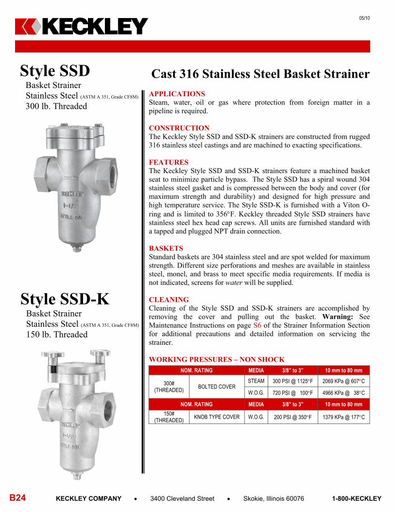
Cast 316 Stainless Steel Basket Strainer APPLICATIONS Steam, water, oil or gas where protection from foreign matter in a pipeline is required.
CONSTRUCTION The Keckley Style SSD and SSD-K strainers are constructed from rugged 316 stainless steel castings and are machined to exacting specifications. FEATURES The Keckley Style SSD and SSD-K strainers feature a machined basket seat to minimize particle bypass. The Style SSD has a spiral wound 304 stainless steel gasket and is compressed between the body and cover (for maximum strength and durability) and designed for high pressure and high temperature service. The Style SSD-K is furnished with a Viton O-ring and is limited to 356F. Keckley threaded Style SSD strainers have stainless steel hex head cap screws. All units are furnished standard with a tapped and plugged NPT drain connection. BASKETS Standard baskets are 304 stainless steel and are spot welded for maximum strength. Different size perforations and meshes are available in stainless steel, monel, and brass to meet specific media requirements. If media is not indicated, screens for water will be supplied. CLEANING Cleaning of the Style SSD and SSD-K strainers are accomplished by removing the cover and pulling out the basket. Warning: See Maintenance Instructions on page S6 of the Strainer Information Section for additional precautions and detailed information on servicing the strainer. WORKING PRESSURES – NON SHOCK
NOM. RATING MEDIA 3/8” to 3” 10 mm to 80 mm
300# (THREADED)
BOLTED COVER STEAM 300 PSI @ 1125F 2069 KPa @ 607C
W.O.G. 720 PSI @ 100F 4966 KPa @ 38C
NOM. RATING MEDIA 3/8” to 3” 10 mm to 80 mm
150# (THREADED)
KNOB TYPE COVER W.O.G. 200 PSI @ 350F 1379 KPa @ 177C
Style SSD
Basket Strainer Stainless Steel (ASTM A 351, Grade CF8M)
300 lb. Threaded
KECKLEY
Style SSD-K
Basket Strainer Stainless Steel (ASTM A 351, Grade CF8M)
150 lb. Threaded
05/10
KECKLEY COMPANY 3400 Cleveland Street Skokie, Illinois 60076 1-800-KECKLEY B25
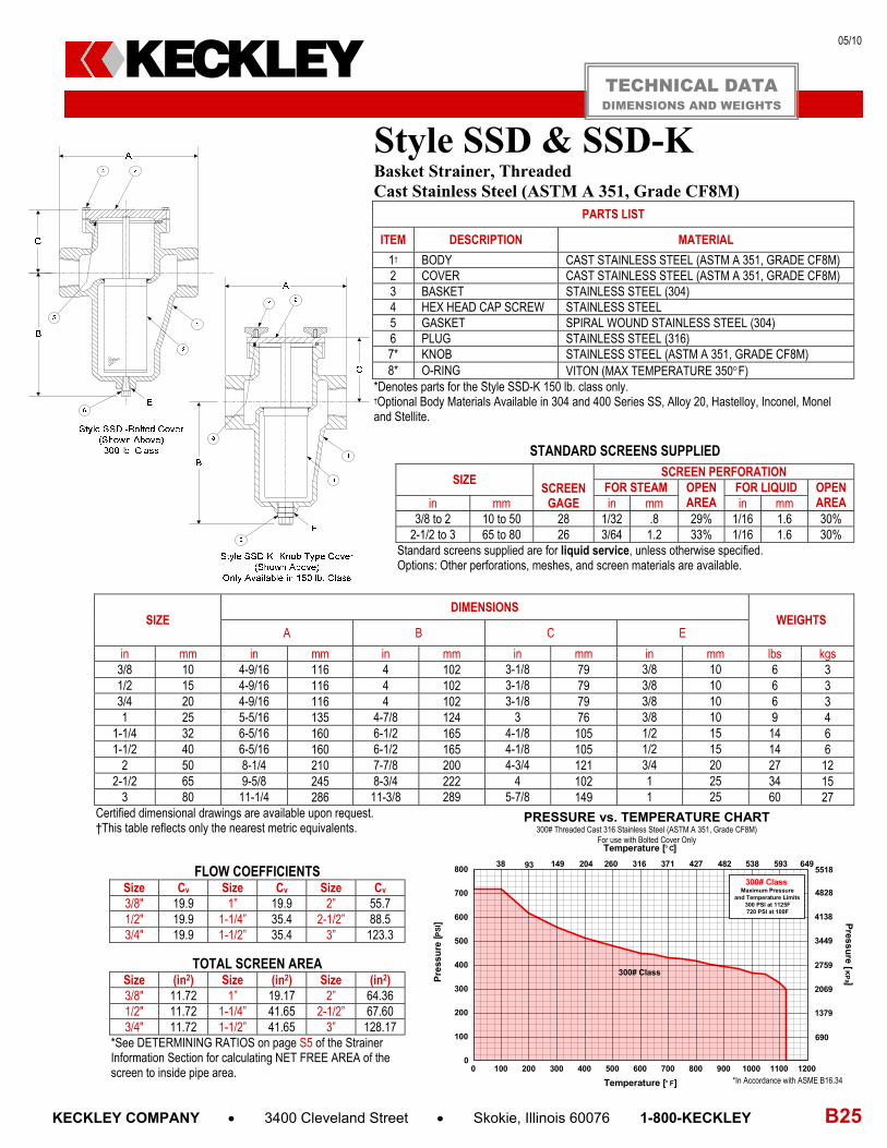
Style SSD & SSD-K Basket Strainer, Threaded Cast Stainless Steel (ASTM A 351, Grade CF8M)
PARTS LIST
ITEM DESCRIPTION MATERIAL
1† BODY CAST STAINLESS STEEL (ASTM A 351, GRADE CF8M) 2 COVER CAST STAINLESS STEEL (ASTM A 351, GRADE CF8M) 3 BASKET STAINLESS STEEL (304) 4 HEX HEAD CAP SCREW STAINLESS STEEL 5 GASKET SPIRAL WOUND STAINLESS STEEL (304) 6 PLUG STAINLESS STEEL (316) 7* KNOB STAINLESS STEEL (ASTM A 351, GRADE CF8M) 8* O-RING VITON (MAX TEMPERATURE 350F)
*Denotes parts for the Style SSD-K 150 lb. class only. †Optional Body Materials Available in 304 and 400 Series SS, Alloy 20, Hastelloy, Inconel, Monel and Stellite.
STANDARD SCREENS SUPPLIED
SIZE SCREEN
GAGE
SCREEN PERFORATION FOR STEAM OPEN
AREA FOR LIQUID OPEN
AREA in mm in mm in mm 3/8 to 2 10 to 50 28 1/32 .8 29% 1/16 1.6 30%
2-1/2 to 3 65 to 80 26 3/64 1.2 33% 1/16 1.6 30% Standard screens supplied are for liquid service, unless otherwise specified. Options: Other perforations, meshes, and screen materials are available.
SIZE DIMENSIONS
WEIGHTS A B C E
in mm in mm in mm in mm in mm lbs kgs 3/8 10 4-9/16 116 4 102 3-1/8 79 3/8 10 6 3 1/2 15 4-9/16 116 4 102 3-1/8 79 3/8 10 6 3 3/4 20 4-9/16 116 4 102 3-1/8 79 3/8 10 6 3 1 25 5-5/16 135 4-7/8 124 3 76 3/8 10 9 4
1-1/4 32 6-5/16 160 6-1/2 165 4-1/8 105 1/2 15 14 6 1-1/2 40 6-5/16 160 6-1/2 165 4-1/8 105 1/2 15 14 6
2 50 8-1/4 210 7-7/8 200 4-3/4 121 3/4 20 27 12 2-1/2 65 9-5/8 245 8-3/4 222 4 102 1 25 34 15
3 80 11-1/4 286 11-3/8 289 5-7/8 149 1 25 60 27 Certified dimensional drawings are available upon request. †This table reflects only the nearest metric equivalents.
FLOW COEFFICIENTS Size Cv Size Cv Size Cv 3/8" 19.9 1” 19.9 2” 55.7 1/2" 19.9 1-1/4” 35.4 2-1/2” 88.5 3/4" 19.9 1-1/2” 35.4 3” 123.3
TOTAL SCREEN AREA Size (in2) Size (in2) Size (in2) 3/8" 11.72 1” 19.17 2” 64.36 1/2" 11.72 1-1/4” 41.65 2-1/2” 67.60 3/4" 11.72 1-1/2” 41.65 3” 128.17
*See DETERMINING RATIOS on page S5 of the Strainer Information Section for calculating NET FREE AREA of the screen to inside pipe area.
TECHNICAL DATA DIMENSIONS AND WEIGHTS
KECKLEY
*In Accordance with ASME B16.34
PRESSURE vs. TEMPERATURE CHART 300# Threaded Cast 316 Stainless Steel (ASTM A 351, Grade CF8M)
For use with Bolted Cover Only
300# Class
0 100 200 300 400 500 600 700 800 900 1000 1100 12000
100
200
300
400
500
600
700
800
300# ClassMaximum Pressure
and Temperature Limits300 PSI at 1125F720 PSI at 100F
Pressu
re [K
Pa ]P
ress
ure
[PS
I ]
Temperature [F]
Temperature [C]
38 93 149 204 260 316 371 427 482 538 5935518
4828
4138
3449
2759
2069
1379
690
649

05/10
B26 KECKLEY COMPANY 3400 Cleveland Street Skokie, Illinois 60076 1-800-KECKLEY
Cast 316 Stainless Steel Basket Strainer APPLICATIONS Steam, water, oil or gas where protection from foreign matter in a pipeline is required.
CONSTRUCTION The Keckley Style SSGFV and SSGFV-K strainers are constructed from rugged 316 stainless steel castings and are machined to exacting specifications. These bodies have raised faced and drilled flanges that are in accordance with ASME B16.5. All flanges come standard with back-faced bolt holes.
FEATURES The Keckley Style SSGFV and SSGFV-K strainers feature a basket with an angular cutaway design to allow straight through flow and extremely low pressure loss. The Style SSGFV has a bolted top cover flange for ease in basket removal. The Style SSGFV-K is furnished with studs and knobs for easy cleaning. The Style SSGFV gasket is spiral wound 304 stainless steel and is compressed between the body and cover (for maximum strength and durability) and designed for high pressure and high temperature service. The Style SSGFV-K is furnished with a Viton gasket suitable for temperatures to 400F. Keckley Style SSGFV strainers have stainless steel hex head cap screws and are furnished standard with a tapped and plugged NPT drain connection.
BASKETS Standard baskets are 304 stainless steel and are spot welded for maximum strength. Different size perforations and meshes are available in stainless steel, monel, and brass to meet specific media requirements. If media is not indicated, screens for water will be supplied.
CLEANING Cleaning of the Style SSGFV and SSGFV-K strainers are accomplished by removing the cover and pulling out the basket. Warning: See Maintenance Instructions on page S6 of the Strainer Information Section for additional precautions and detailed information on servicing the strainer.
WORKING PRESSURES – SHOCK NOM. RATING MEDIA 2” to 12” 50 mm to 300 mm
150# R.F.& D. (FLANGE)
BOLTED COVER STEAM 150 PSI @ 565F 1035 KPa @ 296C
W.O.G. 275 PSI @ 100F 1897 KPa @ 38C
KNOB TYPE COVER W.O.G. 200 PSI @ 375F 1379 KPa @ 191C
NOM. RATING MEDIA 2” to 12” 50 mm to 300 mm
300# R.F.& D. (FLANGE)
BOLTED COVER STEAM 300 PSI @ 1125F 2069 KPa @ 448C
W.O.G. 720 PSI @ 100F 4966 KPa @ 38C
Style SSGFV
Basket Strainer Stainless Steel (ASTM A 351, Grade CF8M)
150 lb. & 300 lb. Flanged
KECKLEY
Style SSGFV-K
Basket Strainer Stainless Steel (ASTM A 351, Grade CF8M)
150 lb. Flanged

05/10
KECKLEY COMPANY 3400 Cleveland Street Skokie, Illinois 60076 1-800-KECKLEY B27
Styles SSGFV & SSGFV-KBasket Strainer, Flanged Cast 316 Stainless Steel (ASTM A 351, Grade CF8M)
PARTS LIST
ITEM DESCRIPTION MATERIAL 1† BODY CAST STAINLESS STEEL (ASTM A 351, GRADE CF8M) 2 BASKET STAINLESS STEEL (304) 3 GASKET SPIRAL WOUND STAINLESS STEEL (304) 4 COVER CAST STAINLESS STEEL (ASTM A 351, GRADE CF8M) 5 PIPE PLUG STAINLESS STEEL (316) 6 HEX HEAD CAP SCREW STAINLESS STEEL (316) 7* KNOB STAINLESS STEEL 8* GASKET VITON (MAX TEMPERATURE 400F)
*Denotes parts for the Style SSGFV-K 150 lb. Class only. †Optional Body Materials Available in 304 and 400 Series SS, Alloy 20, Hastelloy, Inconel, Monel and Stellite.
STANDARD SCREENS SUPPLIED
SIZE SCREEN
GAGE
SCREEN PERFORATION FOR STEAM OPEN
AREA FOR LIQUID OPEN
AREA in mm in mm in mm 1-1/2 to 3 40 to 80 22 3/64 1.2 33% 1/16 1.6 30%
4 to 14 100 to 350 22 1/16 1.6 30% 1/8 3.2 43% Standard screens supplied are for liquid service, unless otherwise specified. Options: Other perforations, meshes, and screen materials are available.
SIZE
DIMENSIONS
A B C E
150# 300# 150# 300# 150# 300# 150# 300# in mm in mm in mm in mm in mm in mm in mm in mm in mm
1-1/2 40 6-1/2 165 7 178 4-1/2 114 4 102 4 102 3-3/4 95 1/2 15 1/2 15 2 50 8-1/2 216 8-13/16 224 5-7/8 149 4-3/4 121 4-3/4 121 3-3/4 95 1/2 15 1 25
2-1/2 65 8 203 9 229 5-7/16 138 5-5/8 143 4-1/4 108 4-5/8 117 3/4 20 1 25 3 80 8-3/4 222 10-1/16 256 5-11/16 144 5-11/16 144 5-5/8 143 5-5/8 143 3/4 20 3/4 20 4 100 11-3/16 284 12 305 8-1/4 210 8-1/4 210 6-1/16 154 6-1/16 154 1 25 1 25 5 125 12-1/4 311 13-1/8 333 10-1/4 260 10-1/4 260 5-5/8 143 5-5/8 143 1 25 1 25 6 150 13-7/8 352 15-9/16 395 12-13/64 310 12-13/64 310 6-5/16 160 6-5/16 160 1-1/4 32 1-1/4 32 8 200 17-3/8 441 18-7/8 479 15-9/16 395 15-9/16 395 8-3/16 208 8-3/16 208 1-1/2 40 1-1/2 40 10 250 22 559 21-5/16 541 16 406 14-3/8 365 10-3/8 264 9-7/8 251 1-1/2 40 2 50 12 300 25 635 25-3/8 645 23-3/4 603 23-3/4 603 12-3/8 314 12-3/8 314 2 50 2 50 14 350 34-5/16 871 34-5/16 871 28 711 34-3/8 873 16-1/2 419 20-3/16 513 2 50 2 50
Larger sizes available upon request. Certified dimensional drawings are available upon request.
FLOW COEFFICIENTS
Size Cv Size Cv Size Cv Size Cv 1-1/2” 32 3” 120.2 6” 743.1 12” 4980.6
2” 42.7 4” 276.7 8” 1486.3 14” 7600.0 2-1/2” 84 5” 442.7 10” 3051.6
TOTAL SCREEN AREA (150 LB.)
Size (in2) Size (in2) Size (in2) Size (in2) 1-1/2” 20.10 3” 54.53 6” 215.65 12” 1040.63
2” 53.42 4” 117.94 8” 401.76 14” 1200.0 2-1/2” 45.72 5” 129.0 10” 591.73
*See DETERMINING RATIOS on page S5 of the Strainer Information Section for calculating NET FREE AREA of the screen to inside pipe area.
WEIGHTS Size 1-1/2” 2” 2-1/2” 3” 4” 5” 6” 8” 10” 12” 14”
150 lbs 22 30 35 39 69 110 125 270 360 450 1550 kgs 10 14 16 18 31 50 57 122 163 204 703
300 Lbs 24 32 42 56 88 126 150 295 420 500 1650 kgs 11 15 19 25 40 57 68 134 191 227 748
TECHNICAL DATA DIMENSIONS AND WEIGHTS
KECKLEY
*In Accordance with ASME B16.5
PRESSURE vs. TEMPERATURE CHART150# & 300# Flanged Cast 316 Stainless Steel (ASTM A 351, Grade CF8M)
For use with Bolted Cover Only
150# Class
300# Class
0 100 200 300 400 500 600 700 800 900 1000 1100 12000
100
200
300
400
500
600
700
800
150# ClassMaximum Pressure
and Temperature Limits150 PSI at 565F275 PSI at 100F
300# ClassMaximum Pressure
and Temperature Limits300 PSI at 1125F720 PSI at 100F
Pres
sure [
KP
a ]Pre
ssu
re [P
SI ]
Temperature [F]
Temperature [C]
38 93 149 204 260 316 371 427 482 538 5935518
4828
4138
3449
2759
2069
1379
690
649

05/10
B28 KECKLEY COMPANY 3400 Cleveland Street Skokie, Illinois 60076 1-800-KECKLEY
PRESSURE DROP CHART Basket Strainers (Styles D, DV, BD, BDV, SD, SD-K, SSD, and SSD-K)
KECKLEY
This pressure drop chart is based on the flow of clean water through the Keckley Strainer Styles listed above with screen perforations ranging from 3/64” through 1/8”.
TO USE CHARTS: Find your desired rate of flow (GPM) on the left hand side of the chart. Follow its corresponding horizontal line to the point where it intersects the diagonal line indicating the strainer pipe size. From this point of intersection, follow the vertical line down to the bottom of the chart to determine the approximate pressure drop.
CORRECTION FACTORS: For finer mesh screens that are backed with a perforated sheet, multiply the pressure drops shown at right by the following: 40 mesh x 1.2 60 mesh x 1.4 80 mesh x 1.6 100 mesh x 1.7
0.1
0.2
0.3
0.4
0.5
0.6
0.7
0.8
0.9 2 3 4 5 6 7 8 91
10
PRESSURE LOSS - [PSI]
5
6
789
10
20
30
40
50
60
708090
100
200
300
400
500
600
700800900
1000
2000
3000
4000
5000
6000
7000
10
100
1000
FL
OW
RA
TE
- [
GP
M]
½", ¾"1"
1¼"1½"
2"
2½"
3"
4"
5"6"
8"
10"
12"

05/10
KECKLEY COMPANY 3400 Cleveland Street Skokie, Illinois 60076 1-800-KECKLEY B29
PRESSURE DROP CHART Basket Strainers (Styles GFV, HLC, BGFV, SGFV, SGFV-K, SSGFV, and SSGFV-K)
KECKLEY
This pressure drop chart is based on the flow of clean water through the Keckley Strainer Styles listed above with screen perforations ranging from 1/16” through 1/8”.
TO USE CHARTS: Find your desired rate of flow (GPM) on the left hand side of the chart. Follow its corresponding horizontal line to the point where it intersects the diagonal line indicating the strainer pipe size. From this point of intersection, follow the vertical line down to the bottom of the chart to determine the approximate pressure drop.
CORRECTION FACTORS: For finer mesh screens that are backed with a perforated sheet, multiply the pressure drops shown at right by the following: 40 mesh x 1.2 60 mesh x 1.4 80 mesh x 1.6 100 mesh x 1.7
0.1
0.2
0.3
0.4
0.5
0.6
0.7
0.8
0.9 2 3 4 5 6 7 8 91
10
PRESSURE LOSS - [PSI]
10
20
30
40
50
60708090
100
200
300
400
500
600700800900
1000
2000
3000
4000
5000
6000700080009000
10000
20000
30000
40000
10
100
1000
10000
FL
OW
RA
TE
- [
GP
M]
2"
2½"
3"
4"
5"
6"
8"
10"
12"
14"16"

05/10
B30 KECKLEY COMPANY 3400 Cleveland Street Skokie, Illinois 60076 1-800-KECKLEY
PRESSURE DROP CHART Basket Strainers (Styles KF-7 and BKF-7)
KECKLEY
This pressure drop chart is based on the flow of clean water through the Keckley Strainer Styles listed above with screen perforations ranging from 3/64” through 1/4”.
TO USE CHARTS: Find your desired rate of flow (GPM) on the left hand side of the chart. Follow its corresponding horizontal line to the point where it intersects the diagonal line indicating the strainer pipe size. From this point of intersection, follow the vertical line down to the bottom of the chart to determine the approximate pressure drop.
CORRECTION FACTORS: For finer mesh screens that are backed with a perforated sheet, multiply the pressure drops shown at right by the following: 40 mesh x 1.2 60 mesh x 1.4 80 mesh x 1.6 100 mesh x 1.7
0.1
0.2
0.3
0.4
0.5
0.6
0.7
0.8
0.9 1 2 3 4 5 6 7 8 9 10
PRESSURE LOSS - [PSI]
10
20
30
40
50
60
70
8090
100
200
300
400
500
600
700
800900
1000
2000
3000
4000
5000
6000
7000
80009000
10000F
LO
W R
AT
E -
[G
PM
] 1½"
2"
2½"
3"
4"
6"
8"
10"
12"

07/11
KECKLEY COMPANY 3400 Cleveland Street Skokie, Illinois 60076 1-800-KECKLEY B31
10
PRESSURE LOSS - [PSI]
4
5
6
7
8
9
10
20
30
40
50
60
70
80
90
100
200
300
400
500
600
10
FL
OW
RA
TE
- [
GP
M]
½", ¾"
1"
1¼"
1½"
2"
2½"
3"
1 2 3 4 5 6 7 8 9
0.1
0.2
0.3
0.4
0.5
0.6
0.7
0.8
0.9
PRESSURE DROP CHART Basket Strainers (KT-7)
KECKLEY
This pressure drop chart is based on the flow of clean water through the Keckley Strainer Styles listed above with screen perforations ranging from 1/16” through 1/8”.
TO USE CHARTS: Find your desired rate of flow (GPM) on the left hand side of the chart. Follow its corresponding horizontal line to the point where it intersects the diagonal line indicating the strainer pipe size. From this point of intersection, follow the vertical line down to the bottom of the chart to determine the approximate pressure drop.
CORRECTION FACTORS: For finer mesh screens that are backed with a perforated sheet, multiply the pressure drops shown at right by the following: 40 mesh x 1.2 60 mesh x 1.4 80 mesh x 1.6 100 mesh x 1.7
07/11
KECKLEY COMPANY 3400 Cleveland Street Skokie, Illinois 60076 1-800-KECKLEY B1-E
Alloy 20 Body (ASTM A 351, GRADE CN7M)
Style SSD-A2 300# Threaded ⅜” – 3” ............................. 2 Style SSD-KA2 150# Threaded ⅜” – 3” .......................... 2
Style SSGFV-A2 150# Flange 2” – 14” ........................... 3 Style SSGFV-KA2 150# Flange 2” – 14” ........................ 3 Style SSGFV-A2 300# Flange 2” – 14” ........................... 3
Hastelloy C276 Body (ASTM A 494, GRADE CW12MW)
Style SSD-HC 300# Threaded ⅜” – 3” ............................ 4 Style SSD-KHC 150# Threaded ⅜” – 3” ......................... 4
Style SSGFV-HC 150# Flange 2” – 14” .......................... 5 Style SSGFV-KHC 150# Flange 2” – 14” ........................ 5 Style SSGFV-HC 300# Flange 2” – 14” .......................... 5
Monel Body (ASTM A 494, GRADE M35-2)
Style SSD-A2 300# Threaded ⅜” – 3” ............................. 6 Style SSD-KA2 150# Threaded ⅜” – 3” .......................... 6
Style SSGFV-A2 150# Flange 2” – 14” ........................... 7 Style SSGFV-KA2 150# Flange 2” – 14” ........................ 7 Style SSGFV-A2 300# Flange 2” – 14” ........................... 7
Chrome-Moly Body (ASTM A 217, GRADE WC6)
Style SSD-C6 300# Threaded ⅜” – 3” ............................. 8 Style SSD-KC6 150# Threaded ⅜” – 3” .......................... 8
Chrome-Moly Body (Cont) (ASTM A 217, GRADE WC6)
Style SSGFV-C6 150# Flange 2” – 14” ........................... 9 Style SSGFV-KC6 150# Flange 2” – 14” ......................... 9 Style SSGFV-C6 300# Flange 2” – 14” ........................... 9
Chrome-Moly Body (ASTM A 217, GRADE WC9)
Style SSD-C9 300# Threaded ⅜” – 3” ........................... 10 Style SSD-KC9 150# Threaded ⅜” – 3” ........................ 10
Style SSGFV-C9 150# Flange 2” – 14” ......................... 11 Style SSGFV-KC9 150# Flange 2” – 14” ....................... 11 Style SSGFV-C9 300# Flange 2” – 14” ......................... 11
Titanium Body (ASTM B 37, GRADE PD7B)
Style SSD-T7 300# Threaded ⅜” – 3” ............................ 12 Style SSD-KT7 150# Threaded ⅜” – 3” ......................... 12
Style SSGFV-T7 150# Flange 2” – 14” .......................... 13 Style SSGFV-KT7 150# Flange 2” – 14” ....................... 13 Style SSGFV-T7 300# Flange 2” – 14” .......................... 13
Duplex Body (ASTM A 351, GRADE CD4MCu)
Style SSD-DP 300# Threaded ⅜” – 3” ........................... 14 Style SSD-KDP 150# Threaded ⅜” – 3” ........................ 14
Style SSGFV-DP 150# Flange 2” – 14” ......................... 15 Style SSGFV-KDP 150# Flange 2” – 14” ...................... 15 Style SSGFV-DP 300# Flange 2” – 14” ......................... 15
Pressure Drop Charts
Styles SD, SD-K, SSD, and SSD-K ......................................................................16 Styles SGFV, SGFV-K, SSGFV, and SSGFV-K ..................................................17
Basket Strainers
KECKLEY

07/11
B2-E KECKLEY COMPANY 3400 Cleveland Street Skokie, Illinois 60076 1-800-KECKLEY
Style SSD-A2 & SSD-KA2 Basket Strainer, Threaded Cast Alloy 20 (ASTM A 351, Grade CN7M)
PARTS LIST
ITEM DESCRIPTION MATERIAL
1† BODY CAST ALLOY 20 (ASTM A 351, GRADE CN7M) 2 COVER CAST ALLOY 20 (ASTM A 351, GRADE CN7M) 3 BASKET STAINLESS STEEL (304) 4 HEX HEAD CAP SCREW STAINLESS STEEL 5 GASKET SPIRAL WOUND STAINLESS STEEL (304) 6 PLUG STAINLESS STEEL (316) 7* KNOB STAINLESS STEEL (ASTM A 351, GRADE CF8M) 8* O-RING VITON (MAX TEMPERATURE 350F)
*Denotes parts for the Style SSD-K 150 lb. class only. †Optional Body Materials Available in 304 and 400 Series SS, Hastelloy C276, Inconel, Monel and Stellite.
STANDARD SCREENS SUPPLIED
SIZE SCREEN
GAGE
SCREEN PERFORATION FOR STEAM OPEN
AREA FOR LIQUID OPEN
AREA in mm in mm in mm 3/8 to 2 10 to 50 28 1/32 .8 29% 1/16 1.6 30%
2-1/2 to 3 65 to 80 26 3/64 1.2 33% 1/16 1.6 30% Standard screens supplied are for liquid service, unless otherwise specified. Options: Other perforations, meshes, and screen materials are available.
SIZE DIMENSIONS
WEIGHTS A B C E
in mm in mm in mm in mm in mm lbs kgs 3/8 10 4-9/16 116 4 102 3-1/8 79 3/8 10 6 3 1/2 15 4-9/16 116 4 102 3-1/8 79 3/8 10 6 3 3/4 20 4-9/16 116 4 102 3-1/8 79 3/8 10 6 3 1 25 5-5/16 135 4-7/8 124 3 76 3/8 10 9 4
1-1/4 32 6-5/16 160 6-1/2 165 4-1/8 105 1/2 15 14 6 1-1/2 40 6-5/16 160 6-1/2 165 4-1/8 105 1/2 15 14 6
2 50 8-1/4 210 7-7/8 200 4-3/4 121 3/4 20 27 12 2-1/2 65 9-5/8 245 8-3/4 222 4 102 1 25 34 15
3 80 11-1/4 286 11-3/8 289 5-7/8 149 1 25 60 27 Certified dimensional drawings are available upon request. †This table reflects only the nearest metric equivalents.
FLOW COEFFICIENTS Size Cv Size Cv Size Cv 3/8" 19.9 1” 19.9 2” 55.7 1/2" 19.9 1-1/4” 35.4 2-1/2” 88.5 3/4" 19.9 1-1/2” 35.4 3” 123.3
TOTAL SCREEN AREA Size (in2) Size (in2) Size (in2) 3/8" 11.72 1” 19.17 2” 64.36 1/2" 11.72 1-1/4” 41.65 2-1/2” 67.60 3/4" 11.72 1-1/2” 41.65 3” 128.17
*See DETERMINING RATIOS on page S5 of the Strainer Information Section for calculating NET FREE AREA of the screen to inside pipe area.
TECHNICAL DATA DIMENSIONS AND WEIGHTS
KECKLEY

07/11
KECKLEY COMPANY 3400 Cleveland Street Skokie, Illinois 60076 1-800-KECKLEY B3-E
Styles SSGFV-A2 & SSGFV-KA2 Basket Strainer, Flanged Cast Alloy 20 (ASTM A 351, Grade CN7M)
PARTS LIST
ITEM DESCRIPTION MATERIAL 1† BODY CAST ALLOY 20 (ASTM A 351, GRADE CN7M) 2 BASKET STAINLESS STEEL (304) 3 GASKET SPIRAL WOUND STAINLESS STEEL (304) 4 COVER CAST ALLOY 20 (ASTM A 351, GRADE CN7M) 5 PIPE PLUG STAINLESS STEEL (316) 6 HEX HEAD CAP SCREW STAINLESS STEEL (316) 7* KNOB STAINLESS STEEL 8* GASKET VITON (MAX TEMPERATURE 400F)
*Denotes parts for the Style SSGFV-K 150 lb. Class only. †Optional Body Materials Available in 304 and 400 Series SS, Hastelloy, Inconel, Monel and Stellite.
STANDARD SCREENS SUPPLIED
SIZE SCREEN
GAGE
SCREEN PERFORATION FOR STEAM OPEN
AREA FOR LIQUID OPEN
AREA in mm in mm in mm 1-1/2 to 3 40 to 80 22 3/64 1.2 33% 1/16 1.6 30%
4 to 14 100 to 350 22 1/16 1.6 30% 1/8 3.2 43% Standard screens supplied are for liquid service, unless otherwise specified. Options: Other perforations, meshes, and screen materials are available.
SIZE
DIMENSIONS
A B C E
150# 300# 150# 300# 150# 300# 150# 300# in mm in mm in mm in mm in mm in mm in mm in mm in mm
1-1/2 40 6-1/2 165 7 178 4-1/2 114 4 102 4 102 3-3/4 95 1/2 15 1/2 15 2 50 8-1/2 216 8-13/16 224 5-7/8 149 4-3/4 121 4-3/4 121 3-3/4 95 1/2 15 1 25
2-1/2 65 8 203 9 229 5-7/16 138 5-5/8 143 4-1/4 108 4-5/8 117 3/4 20 1 25 3 80 8-3/4 222 10-1/16 256 5-11/16 144 5-11/16 144 5-5/8 143 5-5/8 143 3/4 20 3/4 20 4 100 11-3/16 284 12 305 8-1/4 210 8-1/4 210 6-1/16 154 6-1/16 154 1 25 1 25 5 125 12-1/4 311 13-1/8 333 10-1/4 260 10-1/4 260 5-5/8 143 5-5/8 143 1 25 1 25 6 150 13-7/8 352 15-9/16 395 12-13/64 310 12-13/64 310 6-5/16 160 6-5/16 160 1-1/4 32 1-1/4 32 8 200 17-3/8 441 18-7/8 479 15-9/16 395 15-9/16 395 8-3/16 208 8-3/16 208 1-1/2 40 1-1/2 40 10 250 22 559 21-5/16 541 16 406 14-3/8 365 10-3/8 264 9-7/8 251 1-1/2 40 2 50 12 300 25 635 25-3/8 645 23-3/4 603 23-3/4 603 12-3/8 314 12-3/8 314 2 50 2 50 14 350 34-5/16 871 34-5/16 871 28 711 34-3/8 873 16-1/2 419 20-3/16 513 2 50 2 50
Larger sizes available upon request. Certified dimensional drawings are available upon request.
FLOW COEFFICIENTS
Size Cv Size Cv Size Cv Size Cv 1-1/2” 32 3” 120.2 6” 743.1 12” 4980.6
2” 42.7 4” 276.7 8” 1486.3 14” 7600.0 2-1/2” 84 5” 442.7 10” 3051.6
TOTAL SCREEN AREA (150 LB.)
Size (in2) Size (in2) Size (in2) Size (in2) 1-1/2” 20.10 3” 54.53 6” 215.65 12” 1040.63
2” 53.42 4” 117.94 8” 401.76 14” 1200.0 2-1/2” 45.72 5” 129.0 10” 591.73
*See DETERMINING RATIOS on page S5 of the Strainer Information Section for calculating NET FREE AREA of the screen to inside pipe area.
WEIGHTS Size 1-1/2” 2” 2-1/2” 3” 4” 5” 6” 8” 10” 12” 14”
150 lbs 22 30 35 39 69 110 125 270 360 450 1550 kgs 10 14 16 18 31 50 57 122 163 204 703
300 Lbs 24 32 42 56 88 126 150 295 420 500 1650 kgs 11 15 19 25 40 57 68 134 191 227 748
TECHNICAL DATA DIMENSIONS AND WEIGHTS
KECKLEY

07/11
B4-E KECKLEY COMPANY 3400 Cleveland Street Skokie, Illinois 60076 1-800-KECKLEY
Style SSD-HC & SSD-KHC Basket Strainer, Threaded Cast Hastelloy C276 (ASTM A 494, Grade CW12MW)
PARTS LIST
ITEM DESCRIPTION MATERIAL
1† BODY HASTELLOY C276 (ASTM A 494, GRADE CW12MW) 2 COVER HASTELLOY C276 (ASTM A 494, GRADE CW12MW) 3 BASKET STAINLESS STEEL (304) 4 HEX HEAD CAP SCREW STAINLESS STEEL 5 GASKET SPIRAL WOUND STAINLESS STEEL (304) 6 PLUG STAINLESS STEEL (316) 7* KNOB STAINLESS STEEL (ASTM A 351, GRADE CF8M) 8* O-RING VITON (MAX TEMPERATURE 350F)
*Denotes parts for the Style SSD-K 150 lb. class only. †Optional Body Materials Available in 304 and 400 Series SS, Alloy 20, Inconel, Monel and Stellite.
STANDARD SCREENS SUPPLIED
SIZE SCREEN
GAGE
SCREEN PERFORATION FOR STEAM OPEN
AREA FOR LIQUID OPEN
AREA in mm in mm in mm 3/8 to 2 10 to 50 28 1/32 .8 29% 1/16 1.6 30%
2-1/2 to 3 65 to 80 26 3/64 1.2 33% 1/16 1.6 30% Standard screens supplied are for liquid service, unless otherwise specified. Options: Other perforations, meshes, and screen materials are available.
SIZE DIMENSIONS
WEIGHTS A B C E
in mm in mm in mm in mm in mm lbs kgs 3/8 10 4-9/16 116 4 102 3-1/8 79 3/8 10 6 3 1/2 15 4-9/16 116 4 102 3-1/8 79 3/8 10 6 3 3/4 20 4-9/16 116 4 102 3-1/8 79 3/8 10 6 3 1 25 5-5/16 135 4-7/8 124 3 76 3/8 10 9 4
1-1/4 32 6-5/16 160 6-1/2 165 4-1/8 105 1/2 15 14 6 1-1/2 40 6-5/16 160 6-1/2 165 4-1/8 105 1/2 15 14 6
2 50 8-1/4 210 7-7/8 200 4-3/4 121 3/4 20 27 12 2-1/2 65 9-5/8 245 8-3/4 222 4 102 1 25 34 15
3 80 11-1/4 286 11-3/8 289 5-7/8 149 1 25 60 27 Certified dimensional drawings are available upon request. †This table reflects only the nearest metric equivalents.
FLOW COEFFICIENTS Size Cv Size Cv Size Cv 3/8" 19.9 1” 19.9 2” 55.7 1/2" 19.9 1-1/4” 35.4 2-1/2” 88.5 3/4" 19.9 1-1/2” 35.4 3” 123.3
TOTAL SCREEN AREA Size (in2) Size (in2) Size (in2) 3/8" 11.72 1” 19.17 2” 64.36 1/2" 11.72 1-1/4” 41.65 2-1/2” 67.60 3/4" 11.72 1-1/2” 41.65 3” 128.17
*See DETERMINING RATIOS on page S5 of the Strainer Information Section for calculating NET FREE AREA of the screen to inside pipe area.
TECHNICAL DATA DIMENSIONS AND WEIGHTS
KECKLEY

07/11
KECKLEY COMPANY 3400 Cleveland Street Skokie, Illinois 60076 1-800-KECKLEY B5-E
Styles SSGFV-HC & SSGFV-KHCBasket Strainer, Flanged Cast Hastelloy C276 (ASTM A 494, Grade CW12MW)
PARTS LIST
ITEM DESCRIPTION MATERIAL 1† BODY HASTELLOY C276 (ASTM A 494, GRADE CW12MW) 2 BASKET STAINLESS STEEL (304) 3 GASKET SPIRAL WOUND STAINLESS STEEL (304) 4 COVER HASTELLOY C276 (ASTM A 494, GRADE CW12MW) 5 PIPE PLUG STAINLESS STEEL (316) 6 HEX HEAD CAP SCREW STAINLESS STEEL (316) 7* KNOB STAINLESS STEEL 8* GASKET VITON (MAX TEMPERATURE 400F)
*Denotes parts for the Style SSGFV-K 150 lb. Class only. †Optional Body Materials Available in 304 and 400 Series SS, Alloy 20, Inconel, Monel and Stellite.
STANDARD SCREENS SUPPLIED
SIZE SCREEN
GAGE
SCREEN PERFORATION FOR STEAM OPEN
AREA FOR LIQUID OPEN
AREA in mm in mm in mm 1-1/2 to 3 40 to 80 22 3/64 1.2 33% 1/16 1.6 30%
4 to 14 100 to 350 22 1/16 1.6 30% 1/8 3.2 43% Standard screens supplied are for liquid service, unless otherwise specified. Options: Other perforations, meshes, and screen materials are available.
SIZE
DIMENSIONS
A B C E
150# 300# 150# 300# 150# 300# 150# 300# in mm in mm in mm in mm in mm in mm in mm in mm in mm
1-1/2 40 6-1/2 165 7 178 4-1/2 114 4 102 4 102 3-3/4 95 1/2 15 1/2 15 2 50 8-1/2 216 8-13/16 224 5-7/8 149 4-3/4 121 4-3/4 121 3-3/4 95 1/2 15 1 25
2-1/2 65 8 203 9 229 5-7/16 138 5-5/8 143 4-1/4 108 4-5/8 117 3/4 20 1 25 3 80 8-3/4 222 10-1/16 256 5-11/16 144 5-11/16 144 5-5/8 143 5-5/8 143 3/4 20 3/4 20 4 100 11-3/16 284 12 305 8-1/4 210 8-1/4 210 6-1/16 154 6-1/16 154 1 25 1 25 5 125 12-1/4 311 13-1/8 333 10-1/4 260 10-1/4 260 5-5/8 143 5-5/8 143 1 25 1 25 6 150 13-7/8 352 15-9/16 395 12-13/64 310 12-13/64 310 6-5/16 160 6-5/16 160 1-1/4 32 1-1/4 32 8 200 17-3/8 441 18-7/8 479 15-9/16 395 15-9/16 395 8-3/16 208 8-3/16 208 1-1/2 40 1-1/2 40 10 250 22 559 21-5/16 541 16 406 14-3/8 365 10-3/8 264 9-7/8 251 1-1/2 40 2 50 12 300 25 635 25-3/8 645 23-3/4 603 23-3/4 603 12-3/8 314 12-3/8 314 2 50 2 50 14 350 34-5/16 871 34-5/16 871 28 711 34-3/8 873 16-1/2 419 20-3/16 513 2 50 2 50
Larger sizes available upon request. Certified dimensional drawings are available upon request.
FLOW COEFFICIENTS
Size Cv Size Cv Size Cv Size Cv 1-1/2” 32 3” 120.2 6” 743.1 12” 4980.6
2” 42.7 4” 276.7 8” 1486.3 14” 7600.0 2-1/2” 84 5” 442.7 10” 3051.6
TOTAL SCREEN AREA (150 LB.)
Size (in2) Size (in2) Size (in2) Size (in2) 1-1/2” 20.10 3” 54.53 6” 215.65 12” 1040.63
2” 53.42 4” 117.94 8” 401.76 14” 1200.0 2-1/2” 45.72 5” 129.0 10” 591.73
*See DETERMINING RATIOS on page S5 of the Strainer Information Section for calculating NET FREE AREA of the screen to inside pipe area.
WEIGHTS Size 1-1/2” 2” 2-1/2” 3” 4” 5” 6” 8” 10” 12” 14”
150 lbs 22 30 35 39 69 110 125 270 360 450 1550 kgs 10 14 16 18 31 50 57 122 163 204 703
300 Lbs 24 32 42 56 88 126 150 295 420 500 1650 kgs 11 15 19 25 40 57 68 134 191 227 748
TECHNICAL DATA DIMENSIONS AND WEIGHTS
KECKLEY

07/11
B6-E KECKLEY COMPANY 3400 Cleveland Street Skokie, Illinois 60076 1-800-KECKLEY
Style SSD-ML & SSD-ML Basket Strainer, Threaded Cast Monel (ASTM A 494, Grade M35-2)
PARTS LIST
ITEM DESCRIPTION MATERIAL
1† BODY MONEL (ASTM A 494, GRADE M35-2) 2 COVER MONEL (ASTM A 494, GRADE M35-2) 3 BASKET STAINLESS STEEL (304) 4 HEX HEAD CAP SCREW STAINLESS STEEL 5 GASKET SPIRAL WOUND STAINLESS STEEL (304) 6 PLUG STAINLESS STEEL (316) 7* KNOB STAINLESS STEEL (ASTM A 351, GRADE CF8M) 8* O-RING VITON (MAX TEMPERATURE 350F)
*Denotes parts for the Style SSD-K 150 lb. class only. †Optional Body Materials Available in 304 and 400 Series SS, Alloy 20, Inconel, Hastelloy C276, and Stellite.
STANDARD SCREENS SUPPLIED
SIZE SCREEN
GAGE
SCREEN PERFORATION FOR STEAM OPEN
AREA FOR LIQUID OPEN
AREA in mm in mm in mm 3/8 to 2 10 to 50 28 1/32 .8 29% 1/16 1.6 30%
2-1/2 to 3 65 to 80 26 3/64 1.2 33% 1/16 1.6 30% Standard screens supplied are for liquid service, unless otherwise specified. Options: Other perforations, meshes, and screen materials are available.
SIZE DIMENSIONS
WEIGHTS A B C E
in mm in mm in mm in mm in mm lbs kgs 3/8 10 4-9/16 116 4 102 3-1/8 79 3/8 10 6 3 1/2 15 4-9/16 116 4 102 3-1/8 79 3/8 10 6 3 3/4 20 4-9/16 116 4 102 3-1/8 79 3/8 10 6 3 1 25 5-5/16 135 4-7/8 124 3 76 3/8 10 9 4
1-1/4 32 6-5/16 160 6-1/2 165 4-1/8 105 1/2 15 14 6 1-1/2 40 6-5/16 160 6-1/2 165 4-1/8 105 1/2 15 14 6
2 50 8-1/4 210 7-7/8 200 4-3/4 121 3/4 20 27 12 2-1/2 65 9-5/8 245 8-3/4 222 4 102 1 25 34 15
3 80 11-1/4 286 11-3/8 289 5-7/8 149 1 25 60 27 Certified dimensional drawings are available upon request. †This table reflects only the nearest metric equivalents.
FLOW COEFFICIENTS Size Cv Size Cv Size Cv 3/8" 19.9 1” 19.9 2” 55.7 1/2" 19.9 1-1/4” 35.4 2-1/2” 88.5 3/4" 19.9 1-1/2” 35.4 3” 123.3
TOTAL SCREEN AREA Size (in2) Size (in2) Size (in2) 3/8" 11.72 1” 19.17 2” 64.36 1/2" 11.72 1-1/4” 41.65 2-1/2” 67.60 3/4" 11.72 1-1/2” 41.65 3” 128.17
*See DETERMINING RATIOS on page S5 of the Strainer Information Section for calculating NET FREE AREA of the screen to inside pipe area.
TECHNICAL DATA DIMENSIONS AND WEIGHTS
KECKLEY
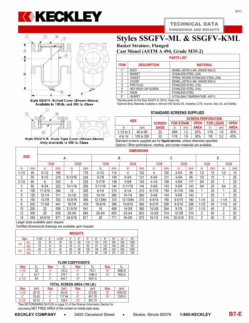
07/11
KECKLEY COMPANY 3400 Cleveland Street Skokie, Illinois 60076 1-800-KECKLEY B7-E
Styles SSGFV-ML & SSGFV-KMLBasket Strainer, Flanged Cast Monel (ASTM A 494, Grade M35-2)
PARTS LIST
ITEM DESCRIPTION MATERIAL 1† BODY MONEL (ASTM A 494, GRADE M35-2) 2 BASKET STAINLESS STEEL (304) 3 GASKET SPIRAL WOUND STAINLESS STEEL (304) 4 COVER MONEL (ASTM A 494, GRADE M35-2) 5 PIPE PLUG STAINLESS STEEL (316) 6 HEX HEAD CAP SCREW STAINLESS STEEL (316) 7* KNOB STAINLESS STEEL 8* GASKET VITON (MAX TEMPERATURE 400F)
*Denotes parts for the Style SSGFV-K 150 lb. Class only. †Optional Body Materials Available in 304 and 400 Series SS, Hastelloy C276, Inconel, Alloy 20, and Stellite.
STANDARD SCREENS SUPPLIED
SIZE SCREEN
GAGE
SCREEN PERFORATION FOR STEAM OPEN
AREA FOR LIQUID OPEN
AREA in mm in mm in mm 1-1/2 to 3 40 to 80 22 3/64 1.2 33% 1/16 1.6 30%
4 to 14 100 to 350 22 1/16 1.6 30% 1/8 3.2 43% Standard screens supplied are for liquid service, unless otherwise specified. Options: Other perforations, meshes, and screen materials are available.
SIZE
DIMENSIONS
A B C E
150# 300# 150# 300# 150# 300# 150# 300# in mm in mm in mm in mm in mm in mm in mm in mm in mm
1-1/2 40 6-1/2 165 7 178 4-1/2 114 4 102 4 102 3-3/4 95 1/2 15 1/2 15 2 50 8-1/2 216 8-13/16 224 5-7/8 149 4-3/4 121 4-3/4 121 3-3/4 95 1/2 15 1 25
2-1/2 65 8 203 9 229 5-7/16 138 5-5/8 143 4-1/4 108 4-5/8 117 3/4 20 1 25 3 80 8-3/4 222 10-1/16 256 5-11/16 144 5-11/16 144 5-5/8 143 5-5/8 143 3/4 20 3/4 20 4 100 11-3/16 284 12 305 8-1/4 210 8-1/4 210 6-1/16 154 6-1/16 154 1 25 1 25 5 125 12-1/4 311 13-1/8 333 10-1/4 260 10-1/4 260 5-5/8 143 5-5/8 143 1 25 1 25 6 150 13-7/8 352 15-9/16 395 12-13/64 310 12-13/64 310 6-5/16 160 6-5/16 160 1-1/4 32 1-1/4 32 8 200 17-3/8 441 18-7/8 479 15-9/16 395 15-9/16 395 8-3/16 208 8-3/16 208 1-1/2 40 1-1/2 40 10 250 22 559 21-5/16 541 16 406 14-3/8 365 10-3/8 264 9-7/8 251 1-1/2 40 2 50 12 300 25 635 25-3/8 645 23-3/4 603 23-3/4 603 12-3/8 314 12-3/8 314 2 50 2 50 14 350 34-5/16 871 34-5/16 871 28 711 34-3/8 873 16-1/2 419 20-3/16 513 2 50 2 50
Larger sizes available upon request. Certified dimensional drawings are available upon request.
FLOW COEFFICIENTS
Size Cv Size Cv Size Cv Size Cv 1-1/2” 32 3” 120.2 6” 743.1 12” 4980.6
2” 42.7 4” 276.7 8” 1486.3 14” 7600.0 2-1/2” 84 5” 442.7 10” 3051.6
TOTAL SCREEN AREA (150 LB.)
Size (in2) Size (in2) Size (in2) Size (in2) 1-1/2” 20.10 3” 54.53 6” 215.65 12” 1040.63
2” 53.42 4” 117.94 8” 401.76 14” 1200.0 2-1/2” 45.72 5” 129.0 10” 591.73
*See DETERMINING RATIOS on page S5 of the Strainer Information Section for calculating NET FREE AREA of the screen to inside pipe area.
WEIGHTS Size 1-1/2” 2” 2-1/2” 3” 4” 5” 6” 8” 10” 12” 14”
150 lbs 22 30 35 39 69 110 125 270 360 450 1550 kgs 10 14 16 18 31 50 57 122 163 204 703
300 Lbs 24 32 42 56 88 126 150 295 420 500 1650 kgs 11 15 19 25 40 57 68 134 191 227 748
TECHNICAL DATA DIMENSIONS AND WEIGHTS
KECKLEY

07/11
B8-E KECKLEY COMPANY 3400 Cleveland Street Skokie, Illinois 60076 1-800-KECKLEY
Style SD-C6 & SD-KC6 Basket Strainer, Threaded Cast Chrome-Moly (ASTM A 217, Grade WC6)
PARTS LIST
ITEM DESCRIPTION MATERIAL
1† BODY CHROME-MOLY (ASTM A 217, GRADE WC6) 2 COVER CHROME-MOLY (ASTM A 217, GRADE WC6) 3 BASKET STAINLESS STEEL (304) 4 HEX HEAD CAP SCREW STAINLESS STEEL 5 GASKET SPIRAL WOUND STAINLESS STEEL (304) 6 PLUG STAINLESS STEEL (316) 7* KNOB STAINLESS STEEL (ASTM A 351, GRADE CF8M) 8* O-RING VITON (MAX TEMPERATURE 350F)
*Denotes parts for the Style SSD-K 150 lb. class only. †Optional Body Materials Available in 304 and 400 Series SS, Alloy 20, Inconel, Hastelloy C276, and Stellite.
STANDARD SCREENS SUPPLIED
SIZE SCREEN
GAGE
SCREEN PERFORATION FOR STEAM OPEN
AREA FOR LIQUID OPEN
AREA in mm in mm in mm 3/8 to 2 10 to 50 28 1/32 .8 29% 1/16 1.6 30%
2-1/2 to 3 65 to 80 26 3/64 1.2 33% 1/16 1.6 30% Standard screens supplied are for liquid service, unless otherwise specified. Options: Other perforations, meshes, and screen materials are available.
SIZE DIMENSIONS
WEIGHTS A B C E
in mm in mm in mm in mm in mm lbs kgs 3/8 10 4-9/16 116 4 102 3-1/8 79 3/8 10 6 3 1/2 15 4-9/16 116 4 102 3-1/8 79 3/8 10 6 3 3/4 20 4-9/16 116 4 102 3-1/8 79 3/8 10 6 3 1 25 5-5/16 135 4-7/8 124 3 76 3/8 10 9 4
1-1/4 32 6-5/16 160 6-1/2 165 4-1/8 105 1/2 15 14 6 1-1/2 40 6-5/16 160 6-1/2 165 4-1/8 105 1/2 15 14 6
2 50 8-1/4 210 7-7/8 200 4-3/4 121 3/4 20 27 12 2-1/2 65 9-5/8 245 8-3/4 222 4 102 1 25 34 15
3 80 11-1/4 286 11-3/8 289 5-7/8 149 1 25 60 27 Certified dimensional drawings are available upon request. †This table reflects only the nearest metric equivalents.
FLOW COEFFICIENTS Size Cv Size Cv Size Cv 3/8" 19.9 1” 19.9 2” 55.7 1/2" 19.9 1-1/4” 35.4 2-1/2” 88.5 3/4" 19.9 1-1/2” 35.4 3” 123.3
TOTAL SCREEN AREA Size (in2) Size (in2) Size (in2) 3/8" 11.72 1” 19.17 2” 64.36 1/2" 11.72 1-1/4” 41.65 2-1/2” 67.60 3/4" 11.72 1-1/2” 41.65 3” 128.17
*See DETERMINING RATIOS on page S5 of the Strainer Information Section for calculating NET FREE AREA of the screen to inside pipe area.
TECHNICAL DATA DIMENSIONS AND WEIGHTS
KECKLEY

07/11
KECKLEY COMPANY 3400 Cleveland Street Skokie, Illinois 60076 1-800-KECKLEY B9-E
Styles SGFV-C6 & SGFV-KC6 Basket Strainer, Flanged Cast Chrome-Moly (ASTM A 217, Grade WC6)
PARTS LIST
ITEM DESCRIPTION MATERIAL 1† BODY CHROME-MOLY (ASTM A 217, GRADE WC6) 2 BASKET STAINLESS STEEL (304) 3 GASKET SPIRAL WOUND STAINLESS STEEL (304) 4 COVER CHROME-MOLY (ASTM A 217, GRADE WC6) 5 PIPE PLUG STAINLESS STEEL (316) 6 HEX HEAD CAP SCREW STAINLESS STEEL (316) 7* KNOB STAINLESS STEEL 8* GASKET VITON (MAX TEMPERATURE 400F)
*Denotes parts for the Style SSGFV-K 150 lb. Class only. †Optional Body Materials Available in 304 and 400 Series SS, Hastelloy C276, Inconel, Alloy 20, and Stellite.
STANDARD SCREENS SUPPLIED
SIZE SCREEN
GAGE
SCREEN PERFORATION FOR STEAM OPEN
AREA FOR LIQUID OPEN
AREA in mm in mm in mm 1-1/2 to 3 40 to 80 22 3/64 1.2 33% 1/16 1.6 30%
4 to 14 100 to 350 22 1/16 1.6 30% 1/8 3.2 43% Standard screens supplied are for liquid service, unless otherwise specified. Options: Other perforations, meshes, and screen materials are available.
SIZE
DIMENSIONS
A B C E
150# 300# 150# 300# 150# 300# 150# 300# in mm in mm in mm in mm in mm in mm in mm in mm in mm
1-1/2 40 6-1/2 165 7 178 4-1/2 114 4 102 4 102 3-3/4 95 1/2 15 1/2 15 2 50 8-1/2 216 8-13/16 224 5-7/8 149 4-3/4 121 4-3/4 121 3-3/4 95 1/2 15 1 25
2-1/2 65 8 203 9 229 5-7/16 138 5-5/8 143 4-1/4 108 4-5/8 117 3/4 20 1 25 3 80 8-3/4 222 10-1/16 256 5-11/16 144 5-11/16 144 5-5/8 143 5-5/8 143 3/4 20 3/4 20 4 100 11-3/16 284 12 305 8-1/4 210 8-1/4 210 6-1/16 154 6-1/16 154 1 25 1 25 5 125 12-1/4 311 13-1/8 333 10-1/4 260 10-1/4 260 5-5/8 143 5-5/8 143 1 25 1 25 6 150 13-7/8 352 15-9/16 395 12-13/64 310 12-13/64 310 6-5/16 160 6-5/16 160 1-1/4 32 1-1/4 32 8 200 17-3/8 441 18-7/8 479 15-9/16 395 15-9/16 395 8-3/16 208 8-3/16 208 1-1/2 40 1-1/2 40 10 250 22 559 21-5/16 541 16 406 14-3/8 365 10-3/8 264 9-7/8 251 1-1/2 40 2 50 12 300 25 635 25-3/8 645 23-3/4 603 23-3/4 603 12-3/8 314 12-3/8 314 2 50 2 50 14 350 34-5/16 871 34-5/16 871 28 711 34-3/8 873 16-1/2 419 20-3/16 513 2 50 2 50
Larger sizes available upon request. Certified dimensional drawings are available upon request.
FLOW COEFFICIENTS
Size Cv Size Cv Size Cv Size Cv 1-1/2” 32 3” 120.2 6” 743.1 12” 4980.6
2” 42.7 4” 276.7 8” 1486.3 14” 7600.0 2-1/2” 84 5” 442.7 10” 3051.6
TOTAL SCREEN AREA (150 LB.)
Size (in2) Size (in2) Size (in2) Size (in2) 1-1/2” 20.10 3” 54.53 6” 215.65 12” 1040.63
2” 53.42 4” 117.94 8” 401.76 14” 1200.0 2-1/2” 45.72 5” 129.0 10” 591.73
*See DETERMINING RATIOS on page S5 of the Strainer Information Section for calculating NET FREE AREA of the screen to inside pipe area.
WEIGHTS Size 1-1/2” 2” 2-1/2” 3” 4” 5” 6” 8” 10” 12” 14”
150 lbs 22 30 35 39 69 110 125 270 360 450 1550 kgs 10 14 16 18 31 50 57 122 163 204 703
300 Lbs 24 32 42 56 88 126 150 295 420 500 1650 kgs 11 15 19 25 40 57 68 134 191 227 748
TECHNICAL DATA DIMENSIONS AND WEIGHTS
KECKLEY

07/11
B10-E KECKLEY COMPANY 3400 Cleveland Street Skokie, Illinois 60076 1-800-KECKLEY
Style SD-C9 & SD-KC9 Basket Strainer, Threaded Cast Chrome-Moly (ASTM A 217, Grade WC9)
PARTS LIST
ITEM DESCRIPTION MATERIAL
1† BODY CHROME-MOLY (ASTM A 217, GRADE WC9) 2 COVER CHROME-MOLY (ASTM A 217, GRADE WC9) 3 BASKET STAINLESS STEEL (304) 4 HEX HEAD CAP SCREW STAINLESS STEEL 5 GASKET SPIRAL WOUND STAINLESS STEEL (304) 6 PLUG STAINLESS STEEL (316) 7* KNOB STAINLESS STEEL (ASTM A 351, GRADE CF8M) 8* O-RING VITON (MAX TEMPERATURE 350F)
*Denotes parts for the Style SSD-K 150 lb. class only. †Optional Body Materials Available in 304 and 400 Series SS, Alloy 20, Inconel, Hastelloy C276, and Stellite.
STANDARD SCREENS SUPPLIED
SIZE SCREEN
GAGE
SCREEN PERFORATION FOR STEAM OPEN
AREA FOR LIQUID OPEN
AREA in mm in mm in mm 3/8 to 2 10 to 50 28 1/32 .8 29% 1/16 1.6 30%
2-1/2 to 3 65 to 80 26 3/64 1.2 33% 1/16 1.6 30% Standard screens supplied are for liquid service, unless otherwise specified. Options: Other perforations, meshes, and screen materials are available.
SIZE DIMENSIONS
WEIGHTS A B C E
in mm in mm in mm in mm in mm lbs kgs 3/8 10 4-9/16 116 4 102 3-1/8 79 3/8 10 6 3 1/2 15 4-9/16 116 4 102 3-1/8 79 3/8 10 6 3 3/4 20 4-9/16 116 4 102 3-1/8 79 3/8 10 6 3 1 25 5-5/16 135 4-7/8 124 3 76 3/8 10 9 4
1-1/4 32 6-5/16 160 6-1/2 165 4-1/8 105 1/2 15 14 6 1-1/2 40 6-5/16 160 6-1/2 165 4-1/8 105 1/2 15 14 6
2 50 8-1/4 210 7-7/8 200 4-3/4 121 3/4 20 27 12 2-1/2 65 9-5/8 245 8-3/4 222 4 102 1 25 34 15
3 80 11-1/4 286 11-3/8 289 5-7/8 149 1 25 60 27 Certified dimensional drawings are available upon request. †This table reflects only the nearest metric equivalents.
FLOW COEFFICIENTS Size Cv Size Cv Size Cv 3/8" 19.9 1” 19.9 2” 55.7 1/2" 19.9 1-1/4” 35.4 2-1/2” 88.5 3/4" 19.9 1-1/2” 35.4 3” 123.3
TOTAL SCREEN AREA Size (in2) Size (in2) Size (in2) 3/8" 11.72 1” 19.17 2” 64.36 1/2" 11.72 1-1/4” 41.65 2-1/2” 67.60 3/4" 11.72 1-1/2” 41.65 3” 128.17
*See DETERMINING RATIOS on page S5 of the Strainer Information Section for calculating NET FREE AREA of the screen to inside pipe area.
TECHNICAL DATA DIMENSIONS AND WEIGHTS
KECKLEY

07/11
KECKLEY COMPANY 3400 Cleveland Street Skokie, Illinois 60076 1-800-KECKLEY B11-E
Styles SGFV-C9 & SGFV-KC9 Basket Strainer, Flanged Cast Chrome-Moly (ASTM A 217, Grade WC9)
PARTS LIST
ITEM DESCRIPTION MATERIAL 1† BODY CHROME-MOLY (ASTM A 217, GRADE WC9) 2 BASKET STAINLESS STEEL (304) 3 GASKET SPIRAL WOUND STAINLESS STEEL (304) 4 COVER CHROME-MOLY (ASTM A 217, GRADE WC9) 5 PIPE PLUG STAINLESS STEEL (316) 6 HEX HEAD CAP SCREW STAINLESS STEEL (316) 7* KNOB STAINLESS STEEL 8* GASKET VITON (MAX TEMPERATURE 400F)
*Denotes parts for the Style SSGFV-K 150 lb. Class only. †Optional Body Materials Available in 304 and 400 Series SS, Hastelloy C276, Inconel, Alloy 20, and Stellite.
STANDARD SCREENS SUPPLIED
SIZE SCREEN
GAGE
SCREEN PERFORATION FOR STEAM OPEN
AREA FOR LIQUID OPEN
AREA in mm in mm in mm 1-1/2 to 3 40 to 80 22 3/64 1.2 33% 1/16 1.6 30%
4 to 14 100 to 350 22 1/16 1.6 30% 1/8 3.2 43% Standard screens supplied are for liquid service, unless otherwise specified. Options: Other perforations, meshes, and screen materials are available.
SIZE
DIMENSIONS
A B C E
150# 300# 150# 300# 150# 300# 150# 300# in mm in mm in mm in mm in mm in mm in mm in mm in mm
1-1/2 40 6-1/2 165 7 178 4-1/2 114 4 102 4 102 3-3/4 95 1/2 15 1/2 15 2 50 8-1/2 216 8-13/16 224 5-7/8 149 4-3/4 121 4-3/4 121 3-3/4 95 1/2 15 1 25
2-1/2 65 8 203 9 229 5-7/16 138 5-5/8 143 4-1/4 108 4-5/8 117 3/4 20 1 25 3 80 8-3/4 222 10-1/16 256 5-11/16 144 5-11/16 144 5-5/8 143 5-5/8 143 3/4 20 3/4 20 4 100 11-3/16 284 12 305 8-1/4 210 8-1/4 210 6-1/16 154 6-1/16 154 1 25 1 25 5 125 12-1/4 311 13-1/8 333 10-1/4 260 10-1/4 260 5-5/8 143 5-5/8 143 1 25 1 25 6 150 13-7/8 352 15-9/16 395 12-13/64 310 12-13/64 310 6-5/16 160 6-5/16 160 1-1/4 32 1-1/4 32 8 200 17-3/8 441 18-7/8 479 15-9/16 395 15-9/16 395 8-3/16 208 8-3/16 208 1-1/2 40 1-1/2 40 10 250 22 559 21-5/16 541 16 406 14-3/8 365 10-3/8 264 9-7/8 251 1-1/2 40 2 50 12 300 25 635 25-3/8 645 23-3/4 603 23-3/4 603 12-3/8 314 12-3/8 314 2 50 2 50 14 350 34-5/16 871 34-5/16 871 28 711 34-3/8 873 16-1/2 419 20-3/16 513 2 50 2 50
Larger sizes available upon request. Certified dimensional drawings are available upon request.
FLOW COEFFICIENTS
Size Cv Size Cv Size Cv Size Cv 1-1/2” 32 3” 120.2 6” 743.1 12” 4980.6
2” 42.7 4” 276.7 8” 1486.3 14” 7600.0 2-1/2” 84 5” 442.7 10” 3051.6
TOTAL SCREEN AREA (150 LB.)
Size (in2) Size (in2) Size (in2) Size (in2) 1-1/2” 20.10 3” 54.53 6” 215.65 12” 1040.63
2” 53.42 4” 117.94 8” 401.76 14” 1200.0 2-1/2” 45.72 5” 129.0 10” 591.73
*See DETERMINING RATIOS on page S5 of the Strainer Information Section for calculating NET FREE AREA of the screen to inside pipe area.
WEIGHTS Size 1-1/2” 2” 2-1/2” 3” 4” 5” 6” 8” 10” 12” 14”
150 lbs 22 30 35 39 69 110 125 270 360 450 1550 kgs 10 14 16 18 31 50 57 122 163 204 703
300 Lbs 24 32 42 56 88 126 150 295 420 500 1650 kgs 11 15 19 25 40 57 68 134 191 227 748
TECHNICAL DATA DIMENSIONS AND WEIGHTS
KECKLEY

07/11
B12-E KECKLEY COMPANY 3400 Cleveland Street Skokie, Illinois 60076 1-800-KECKLEY
Style SSD-T7& SSD-KT7 Basket Strainer, Threaded Cast Titanium (ASTM B 37, Grade PD7B)
PARTS LIST
ITEM DESCRIPTION MATERIAL
1† BODY TITANIUM (ASTM B 37, GRADE PD7B) 2 COVER TITANIUM (ASTM B 37, GRADE PD7B) 3 BASKET STAINLESS STEEL (304) 4 HEX HEAD CAP SCREW STAINLESS STEEL 5 GASKET SPIRAL WOUND STAINLESS STEEL (304) 6 PLUG STAINLESS STEEL (316) 7* KNOB STAINLESS STEEL (ASTM A 351, GRADE CF8M) 8* O-RING VITON (MAX TEMPERATURE 350F)
*Denotes parts for the Style SSD-K 150 lb. class only. †Optional Body Materials Available in 304 and 400 Series SS, Alloy 20, Inconel, Hastelloy C276, and Stellite.
STANDARD SCREENS SUPPLIED
SIZE SCREEN
GAGE
SCREEN PERFORATION FOR STEAM OPEN
AREA FOR LIQUID OPEN
AREA in mm in mm in mm 3/8 to 2 10 to 50 28 1/32 .8 29% 1/16 1.6 30%
2-1/2 to 3 65 to 80 26 3/64 1.2 33% 1/16 1.6 30% Standard screens supplied are for liquid service, unless otherwise specified. Options: Other perforations, meshes, and screen materials are available.
SIZE DIMENSIONS
WEIGHTS A B C E
in mm in mm in mm in mm in mm lbs kgs 3/8 10 4-9/16 116 4 102 3-1/8 79 3/8 10 6 3 1/2 15 4-9/16 116 4 102 3-1/8 79 3/8 10 6 3 3/4 20 4-9/16 116 4 102 3-1/8 79 3/8 10 6 3 1 25 5-5/16 135 4-7/8 124 3 76 3/8 10 9 4
1-1/4 32 6-5/16 160 6-1/2 165 4-1/8 105 1/2 15 14 6 1-1/2 40 6-5/16 160 6-1/2 165 4-1/8 105 1/2 15 14 6
2 50 8-1/4 210 7-7/8 200 4-3/4 121 3/4 20 27 12 2-1/2 65 9-5/8 245 8-3/4 222 4 102 1 25 34 15
3 80 11-1/4 286 11-3/8 289 5-7/8 149 1 25 60 27 Certified dimensional drawings are available upon request. †This table reflects only the nearest metric equivalents.
FLOW COEFFICIENTS Size Cv Size Cv Size Cv 3/8" 19.9 1” 19.9 2” 55.7 1/2" 19.9 1-1/4” 35.4 2-1/2” 88.5 3/4" 19.9 1-1/2” 35.4 3” 123.3
TOTAL SCREEN AREA Size (in2) Size (in2) Size (in2) 3/8" 11.72 1” 19.17 2” 64.36 1/2" 11.72 1-1/4” 41.65 2-1/2” 67.60 3/4" 11.72 1-1/2” 41.65 3” 128.17
*See DETERMINING RATIOS on page S5 of the Strainer Information Section for calculating NET FREE AREA of the screen to inside pipe area.
TECHNICAL DATA DIMENSIONS AND WEIGHTS
KECKLEY

07/11
KECKLEY COMPANY 3400 Cleveland Street Skokie, Illinois 60076 1-800-KECKLEY B13-E
Styles SSGFV-T7 & SSGFV-KT7 Basket Strainer, Flanged Cast Titanium (ASTM B 37, Grade PD7B)
PARTS LIST
ITEM DESCRIPTION MATERIAL 1† BODY TITANIUM (ASTM B 37, GRADE PD7B) 2 BASKET STAINLESS STEEL (304) 3 GASKET SPIRAL WOUND STAINLESS STEEL (304) 4 COVER TITANIUM (ASTM B 37, GRADE PD7B) 5 PIPE PLUG STAINLESS STEEL (316) 6 HEX HEAD CAP SCREW STAINLESS STEEL (316) 7* KNOB STAINLESS STEEL 8* GASKET VITON (MAX TEMPERATURE 400F)
*Denotes parts for the Style SSGFV-K 150 lb. Class only. †Optional Body Materials Available in 304 and 400 Series SS, Hastelloy C276, Inconel, Alloy 20, and Stellite.
STANDARD SCREENS SUPPLIED
SIZE SCREEN
GAGE
SCREEN PERFORATION FOR STEAM OPEN
AREA FOR LIQUID OPEN
AREA in mm in mm in mm 1-1/2 to 3 40 to 80 22 3/64 1.2 33% 1/16 1.6 30%
4 to 14 100 to 350 22 1/16 1.6 30% 1/8 3.2 43% Standard screens supplied are for liquid service, unless otherwise specified. Options: Other perforations, meshes, and screen materials are available.
SIZE
DIMENSIONS
A B C E
150# 300# 150# 300# 150# 300# 150# 300# in mm in mm in mm in mm in mm in mm in mm in mm in mm
1-1/2 40 6-1/2 165 7 178 4-1/2 114 4 102 4 102 3-3/4 95 1/2 15 1/2 15 2 50 8-1/2 216 8-13/16 224 5-7/8 149 4-3/4 121 4-3/4 121 3-3/4 95 1/2 15 1 25
2-1/2 65 8 203 9 229 5-7/16 138 5-5/8 143 4-1/4 108 4-5/8 117 3/4 20 1 25 3 80 8-3/4 222 10-1/16 256 5-11/16 144 5-11/16 144 5-5/8 143 5-5/8 143 3/4 20 3/4 20 4 100 11-3/16 284 12 305 8-1/4 210 8-1/4 210 6-1/16 154 6-1/16 154 1 25 1 25 5 125 12-1/4 311 13-1/8 333 10-1/4 260 10-1/4 260 5-5/8 143 5-5/8 143 1 25 1 25 6 150 13-7/8 352 15-9/16 395 12-13/64 310 12-13/64 310 6-5/16 160 6-5/16 160 1-1/4 32 1-1/4 32 8 200 17-3/8 441 18-7/8 479 15-9/16 395 15-9/16 395 8-3/16 208 8-3/16 208 1-1/2 40 1-1/2 40 10 250 22 559 21-5/16 541 16 406 14-3/8 365 10-3/8 264 9-7/8 251 1-1/2 40 2 50 12 300 25 635 25-3/8 645 23-3/4 603 23-3/4 603 12-3/8 314 12-3/8 314 2 50 2 50 14 350 34-5/16 871 34-5/16 871 28 711 34-3/8 873 16-1/2 419 20-3/16 513 2 50 2 50
Larger sizes available upon request. Certified dimensional drawings are available upon request.
FLOW COEFFICIENTS
Size Cv Size Cv Size Cv Size Cv 1-1/2” 32 3” 120.2 6” 743.1 12” 4980.6
2” 42.7 4” 276.7 8” 1486.3 14” 7600.0 2-1/2” 84 5” 442.7 10” 3051.6
TOTAL SCREEN AREA (150 LB.)
Size (in2) Size (in2) Size (in2) Size (in2) 1-1/2” 20.10 3” 54.53 6” 215.65 12” 1040.63
2” 53.42 4” 117.94 8” 401.76 14” 1200.0 2-1/2” 45.72 5” 129.0 10” 591.73
*See DETERMINING RATIOS on page S5 of the Strainer Information Section for calculating NET FREE AREA of the screen to inside pipe area.
WEIGHTS Size 1-1/2” 2” 2-1/2” 3” 4” 5” 6” 8” 10” 12” 14”
150 lbs 22 30 35 39 69 110 125 270 360 450 1550 kgs 10 14 16 18 31 50 57 122 163 204 703
300 Lbs 24 32 42 56 88 126 150 295 420 500 1650 kgs 11 15 19 25 40 57 68 134 191 227 748
TECHNICAL DATA DIMENSIONS AND WEIGHTS
KECKLEY

07/11
B14-E KECKLEY COMPANY 3400 Cleveland Street Skokie, Illinois 60076 1-800-KECKLEY
Style SSD-DP & SSD-KDP Basket Strainer, Threaded Duplex (ASTM A 351, Grade CD4MCu)
PARTS LIST
ITEM DESCRIPTION MATERIAL
1† BODY DUPLEX (ASTM A 351, GRADE CD4MCu) 2 COVER DUPLEX (ASTM A 351, GRADE CD4MCu) 3 BASKET STAINLESS STEEL (304) 4 HEX HEAD CAP SCREW STAINLESS STEEL 5 GASKET SPIRAL WOUND STAINLESS STEEL (304) 6 PLUG STAINLESS STEEL (316) 7* KNOB STAINLESS STEEL (ASTM A 351, GRADE CF8M) 8* O-RING VITON (MAX TEMPERATURE 350F)
*Denotes parts for the Style SSD-K 150 lb. class only. †Optional Body Materials Available in 304 and 400 Series SS, Hastelloy C276, Inconel, Monel and Stellite.
STANDARD SCREENS SUPPLIED
SIZE SCREEN
GAGE
SCREEN PERFORATION FOR STEAM OPEN
AREA FOR LIQUID OPEN
AREA in mm in mm in mm 3/8 to 2 10 to 50 28 1/32 .8 29% 1/16 1.6 30%
2-1/2 to 3 65 to 80 26 3/64 1.2 33% 1/16 1.6 30% Standard screens supplied are for liquid service, unless otherwise specified. Options: Other perforations, meshes, and screen materials are available.
SIZE DIMENSIONS
WEIGHTS A B C E
in mm in mm in mm in mm in mm lbs kgs 3/8 10 4-9/16 116 4 102 3-1/8 79 3/8 10 6 3 1/2 15 4-9/16 116 4 102 3-1/8 79 3/8 10 6 3 3/4 20 4-9/16 116 4 102 3-1/8 79 3/8 10 6 3 1 25 5-5/16 135 4-7/8 124 3 76 3/8 10 9 4
1-1/4 32 6-5/16 160 6-1/2 165 4-1/8 105 1/2 15 14 6 1-1/2 40 6-5/16 160 6-1/2 165 4-1/8 105 1/2 15 14 6
2 50 8-1/4 210 7-7/8 200 4-3/4 121 3/4 20 27 12 2-1/2 65 9-5/8 245 8-3/4 222 4 102 1 25 34 15
3 80 11-1/4 286 11-3/8 289 5-7/8 149 1 25 60 27 Certified dimensional drawings are available upon request. †This table reflects only the nearest metric equivalents.
FLOW COEFFICIENTS Size Cv Size Cv Size Cv 3/8" 19.9 1” 19.9 2” 55.7 1/2" 19.9 1-1/4” 35.4 2-1/2” 88.5 3/4" 19.9 1-1/2” 35.4 3” 123.3
TOTAL SCREEN AREA Size (in2) Size (in2) Size (in2) 3/8" 11.72 1” 19.17 2” 64.36 1/2" 11.72 1-1/4” 41.65 2-1/2” 67.60 3/4" 11.72 1-1/2” 41.65 3” 128.17
*See DETERMINING RATIOS on page S5 of the Strainer Information Section for calculating NET FREE AREA of the screen to inside pipe area.
TECHNICAL DATA DIMENSIONS AND WEIGHTS
KECKLEY
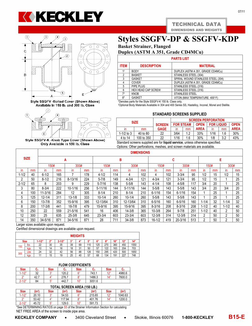
07/11
KECKLEY COMPANY 3400 Cleveland Street Skokie, Illinois 60076 1-800-KECKLEY B15-E
Styles SSGFV-DP & SSGFV-KDPBasket Strainer, Flanged Duplex (ASTM A 351, Grade CD4MCu)
PARTS LIST
ITEM DESCRIPTION MATERIAL 1† BODY DUPLEX (ASTM A 351, GRADE CD4MCu) 2 BASKET STAINLESS STEEL (304) 3 GASKET SPIRAL WOUND STAINLESS STEEL (304) 4 COVER DUPLEX (ASTM A 351, GRADE CD4MCu) 5 PIPE PLUG STAINLESS STEEL (316) 6 HEX HEAD CAP SCREW STAINLESS STEEL (316) 7* KNOB STAINLESS STEEL 8* GASKET VITON (MAX TEMPERATURE 400F)
*Denotes parts for the Style SSGFV-K 150 lb. Class only. †Optional Body Materials Available in 304 and 400 Series SS, Hastelloy, Inconel, Monel and Stellite.
STANDARD SCREENS SUPPLIED
SIZE SCREEN
GAGE
SCREEN PERFORATION FOR STEAM OPEN
AREA FOR LIQUID OPEN
AREA in mm in mm in mm 1-1/2 to 3 40 to 80 22 3/64 1.2 33% 1/16 1.6 30%
4 to 14 100 to 350 22 1/16 1.6 30% 1/8 3.2 43% Standard screens supplied are for liquid service, unless otherwise specified. Options: Other perforations, meshes, and screen materials are available.
SIZE
DIMENSIONS
A B C E
150# 300# 150# 300# 150# 300# 150# 300# in mm in mm in mm in mm in mm in mm in mm in mm in mm
1-1/2 40 6-1/2 165 7 178 4-1/2 114 4 102 4 102 3-3/4 95 1/2 15 1/2 15 2 50 8-1/2 216 8-13/16 224 5-7/8 149 4-3/4 121 4-3/4 121 3-3/4 95 1/2 15 1 25
2-1/2 65 8 203 9 229 5-7/16 138 5-5/8 143 4-1/4 108 4-5/8 117 3/4 20 1 25 3 80 8-3/4 222 10-1/16 256 5-11/16 144 5-11/16 144 5-5/8 143 5-5/8 143 3/4 20 3/4 20 4 100 11-3/16 284 12 305 8-1/4 210 8-1/4 210 6-1/16 154 6-1/16 154 1 25 1 25 5 125 12-1/4 311 13-1/8 333 10-1/4 260 10-1/4 260 5-5/8 143 5-5/8 143 1 25 1 25 6 150 13-7/8 352 15-9/16 395 12-13/64 310 12-13/64 310 6-5/16 160 6-5/16 160 1-1/4 32 1-1/4 32 8 200 17-3/8 441 18-7/8 479 15-9/16 395 15-9/16 395 8-3/16 208 8-3/16 208 1-1/2 40 1-1/2 40 10 250 22 559 21-5/16 541 16 406 14-3/8 365 10-3/8 264 9-7/8 251 1-1/2 40 2 50 12 300 25 635 25-3/8 645 23-3/4 603 23-3/4 603 12-3/8 314 12-3/8 314 2 50 2 50 14 350 34-5/16 871 34-5/16 871 28 711 34-3/8 873 16-1/2 419 20-3/16 513 2 50 2 50
Larger sizes available upon request. Certified dimensional drawings are available upon request.
FLOW COEFFICIENTS
Size Cv Size Cv Size Cv Size Cv 1-1/2” 32 3” 120.2 6” 743.1 12” 4980.6
2” 42.7 4” 276.7 8” 1486.3 14” 7600.0 2-1/2” 84 5” 442.7 10” 3051.6
TOTAL SCREEN AREA (150 LB.)
Size (in2) Size (in2) Size (in2) Size (in2) 1-1/2” 20.10 3” 54.53 6” 215.65 12” 1040.63
2” 53.42 4” 117.94 8” 401.76 14” 1200.0 2-1/2” 45.72 5” 129.0 10” 591.73
*See DETERMINING RATIOS on page S5 of the Strainer Information Section for calculating NET FREE AREA of the screen to inside pipe area.
WEIGHTS Size 1-1/2” 2” 2-1/2” 3” 4” 5” 6” 8” 10” 12” 14”
150 lbs 22 30 35 39 69 110 125 270 360 450 1550 kgs 10 14 16 18 31 50 57 122 163 204 703
300 Lbs 24 32 42 56 88 126 150 295 420 500 1650 kgs 11 15 19 25 40 57 68 134 191 227 748
TECHNICAL DATA DIMENSIONS AND WEIGHTS
KECKLEY
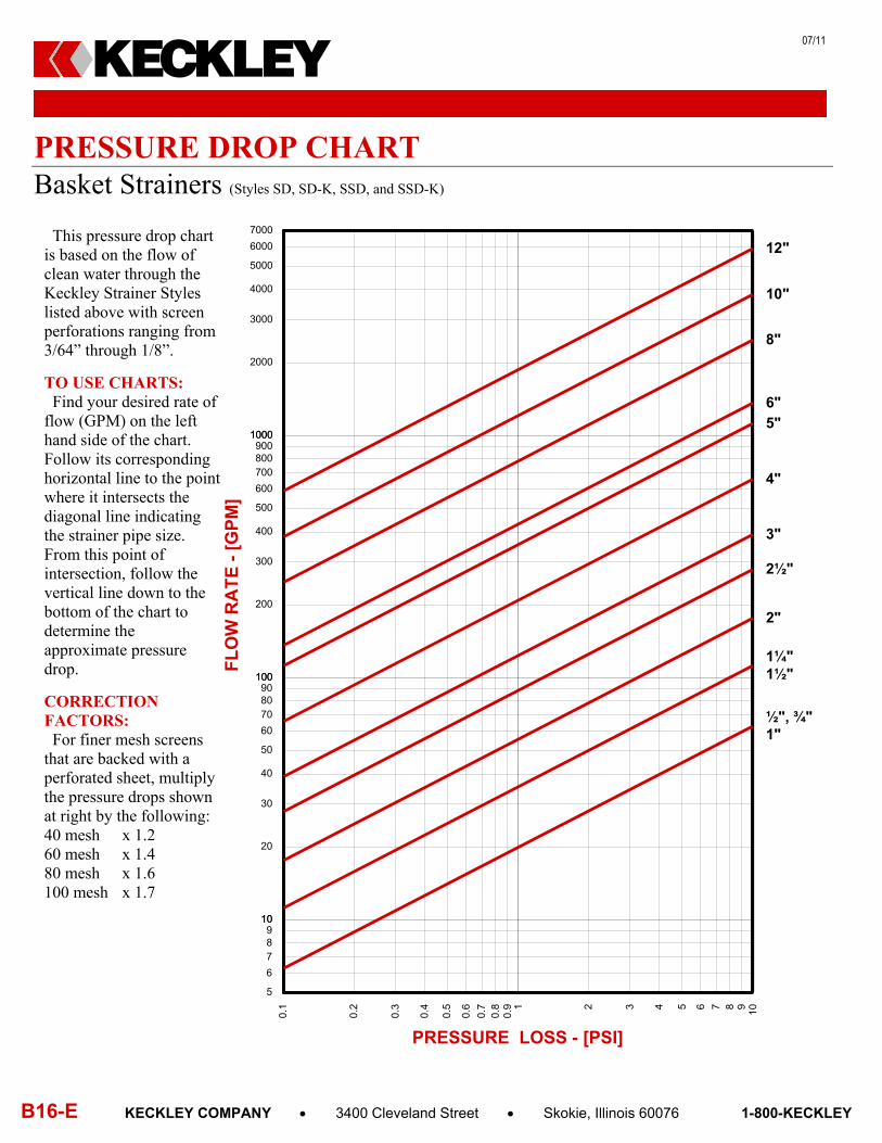
07/11
B16-E KECKLEY COMPANY 3400 Cleveland Street Skokie, Illinois 60076 1-800-KECKLEY
PRESSURE DROP CHART Basket Strainers (Styles SD, SD-K, SSD, and SSD-K)
KECKLEY
This pressure drop chart is based on the flow of clean water through the Keckley Strainer Styles listed above with screen perforations ranging from 3/64” through 1/8”.
TO USE CHARTS: Find your desired rate of flow (GPM) on the left hand side of the chart. Follow its corresponding horizontal line to the point where it intersects the diagonal line indicating the strainer pipe size. From this point of intersection, follow the vertical line down to the bottom of the chart to determine the approximate pressure drop.
CORRECTION FACTORS: For finer mesh screens that are backed with a perforated sheet, multiply the pressure drops shown at right by the following: 40 mesh x 1.2 60 mesh x 1.4 80 mesh x 1.6 100 mesh x 1.7
0.1
0.2
0.3
0.4
0.5
0.6
0.7
0.8
0.9 2 3 4 5 6 7 8 91
10
PRESSURE LOSS - [PSI]
5
6
789
10
20
30
40
50
60
708090
100
200
300
400
500
600
700800900
1000
2000
3000
4000
5000
6000
7000
10
100
1000
FL
OW
RA
TE
- [
GP
M]
½", ¾"1"
1¼"1½"
2"
2½"
3"
4"
5"6"
8"
10"
12"

07/11
KECKLEY COMPANY 3400 Cleveland Street Skokie, Illinois 60076 1-800-KECKLEY B17-E
PRESSURE DROP CHART Basket Strainers (Styles SGFV, SGFV-K, SSGFV, and SSGFV-K)
KECKLEY
This pressure drop chart is based on the flow of clean water through the Keckley Strainer Styles listed above with screen perforations ranging from 1/16” through 1/8”.
TO USE CHARTS: Find your desired rate of flow (GPM) on the left hand side of the chart. Follow its corresponding horizontal line to the point where it intersects the diagonal line indicating the strainer pipe size. From this point of intersection, follow the vertical line down to the bottom of the chart to determine the approximate pressure drop.
CORRECTION FACTORS: For finer mesh screens that are backed with a perforated sheet, multiply the pressure drops shown at right by the following: 40 mesh x 1.2 60 mesh x 1.4 80 mesh x 1.6 100 mesh x 1.7
0.1
0.2
0.3
0.4
0.5
0.6
0.7
0.8
0.9 2 3 4 5 6 7 8 91
10
PRESSURE LOSS - [PSI]
10
20
30
40
50
60708090
100
200
300
400
500
600700800900
1000
2000
3000
4000
5000
6000700080009000
10000
20000
30000
40000
10
100
1000
10000
FL
OW
RA
TE
- [
GP
M]
2"
2½"
3"
4"
5"
6"
8"
10"
12"
14"16"