assessment results of fluid-structure interaction...
TRANSCRIPT
Marković, Z. J., et al.: Assessment Results of Fluid-Structure Interaction Numerical … THERMAL SCIENCE, Year 2016, Vol. 20, Suppl. 1, pp. S235-S250 S235
ASSESSMENT RESULTS OF FLUID-STRUCTURE INTERACTION NUMERICAL SIMULATION USING FUZZY LOGIC
by
Zoran J. MARKOVI]a*, Slobodan N. STUPAR b, Mirko R. DINULOVI] b,
Ognjen M. PEKOVI] b, Predrag Lj. STEFANOVI] a, and Dejan B. CVETINOVI] a
a Laboratory for Thermal Engineering and Energy, Vinca Institute of Nuclear Sciences, University of Belgrade, Belgrade, Serbia
b Department of Aerospace Engineering, Faculty of Mechanical Engineering, University of Belgrade, Belgrade, Serbia
Original scientific paper DOI: 10.2298/TSCI160111083M
A fuzzy approximation concept is applied in order to predict results of coupled computational structure mechanics and computational fluid dynamics while solv-ing a problem of steady incompressible gas flow through thermally loaded rec-tangular thin-walled channel. Channel wall deforms into wave-type shapes de-pending on thermal load and fluid inlet velocity inducing the changes of fluid flow accordingly. A set of fluid-structure interaction numerical tests have been defined by varying the values of fluid inlet velocity, temperature of inner and out-er surface of the channel wall, and numerical grid density. The unsteady Navier- -Stokes equations are numerically solved using an element-based finite volume method and second order backward Euler discretization scheme. The structural model is solved by finite element method including geometric and material non- -linearities. The implicit two-way iterative code coupling, partitioned solution approach, were used while solving these numerical tests. Results of numerical analysis indicate that gravity and pressure distribution inside the channel con-tributes to triggering the shape of deformation. In the inverse problem, the results of fluid-structure interaction numerical simulations formed a database of input variables for development fuzzy logic based models considering downstream pressure drop and maximum stresses as the objective functions. Developed fuzzy models predicted targeting results within a reasonable accuracy limit at lower computation cost compared to series of fluid-structure interaction numerical cal-culations. Smaller relative difference were obtained when calculating the values of pressure drop then maximal stresses indicating that transfer function influence on output values have to be additionally investigated. Key words: thin-walled structure, fluid-structure interaction,
fuzzy inference model
Introduction
Fluid-structure interaction (FSI) has been the main focus of numerous studies moti-vated by applications in bridge construction [1], aeronautics [2-16], computer hardware design [17] or nuclear [18, 19], but also in biomechanics and medicine [20-22]. Advances in computa-tional mechanics algorithms parallel to continually growing computational resources allowed analysis of coupled fluid-structure problems using computer simulation. Different methods for –––––––––––––– * Corresponding author; e-mail: [email protected]

Marković, Z. J., et al.: Assessment Results of Fluid-Structure Interaction Numerical … S236 THERMAL SCIENCE, Year 2016, Vol. 20, Suppl. 1, pp. S235-S250
modelling fluid-structure coupling have been extensively investigated [15, 23]. Depending on physical problem assumptions, the models of one- [6, 12, 17, 24] or two-way [5, 7-9, 11, 13, 14, 20, 25-27] load transfer, with various coupling mechanisms ranging from partitioned [7-10], weakly [8, 18, 22] coupled approach to strong [1, 10, 17] fully coupled, monolithic schemes, or both [17, 22] coupling strategies were used in order to resolve problems of stability of plates in fluid flow and thin sheet fluttering [2, 16, 28] or fluid-thermal-structure coupled simulation of the response to simultaneous aerodynamic heating and fluctuating pressures [24, 25-27]. A lim-ited number of studies have considered mutual two-way coupling of aerodynamic heating and structural deformation, while some studies have considered thermal effects by prescribing a steady-state temperature distribution, further simplifying problem by neglecting the transient thermal analysis in addition to two-way coupling [25, 27]. The main reason was that time accu-racy and stability of one non-linear fluid-thermal-structural transient analysis is highly sensitive on many modelling issues. The fluid and structural physics operate at significantly smaller time scales than the thermal evolution, thus requiring time marching that can capture the small time scales for time records that encapsulate the longer time scale of the thermal response. A differ-ent time integrators shall be used for each physical field solvers with boundary conditions ex-changed at most once per time step. This led to extreme computational times and minimizes ef-ficiency of the coupled problem time integrations [25, 26].
The FSI is largely relied on numerical simulation of two different physical systems: Eulerian CFD perspective of the fluid model which could be based on different space discreti-zation schemes as finite elements [1], finite difference [3, 12, 19] but frequently on finite vol-ume method [3, 5, 8, 16], and CSM supported by finite element method (FEM), and Lagrangian formulation of the solid [4, 8, 16, 18, 28]. Reliability of the obtained results de-pends on the adopted modelling assumptions and the level of approximation of the simulated physical process. In many practical engineering problems is desirable to implement computa-tional techniques based on limited access to numerical/experimental data which allows obtain-ing reliable necessary information. Emerging soft computing techniques in data processing like neural networks (NN) and fuzzy logic (FL) are widely used to predict performance of complex non-linear systems with limited input data. The NN were implemented to model nu-merical and experimental data for resolving structural analysis problems [29], where the pa-rameter identification is formulated and solved as a learning problem for a NN. A Pade ap-proximants-based perturbation technique were implemented into NN in order to predict total strain energy and maximum displacement of stiffened panels with cut-out [30] as well as post buckling behaviour of the composite panels. The back-propagation NN model trained by the characteristic parameters obtained from FEM based computational structural dynamics (CSD) is used to calculate frequency response of the cracked medium subjected to impact loading [31]. Artificial neural networks (ANN) models gave satisfactory results in prediction of some selective parameters of fluid flow as the velocity field in a 90° bend channel [32], maximum wave run-up on breakwaters [33] or drag force on underwater vehicle [34]. The ANN ap-proach provide high accuracy input-output mapping for non-linear systems modelling, but has one fundamental weakness that is a kind of black box model, incapable of explaining a partic-ular decision to the user in a comprehensible form. The fuzzy inference system (FIS) based on theory of fuzzy sets [35] uses fuzzy reasoning in a form of if-then rules and understandable linguistic terms to map an input to an output space. A FL-based expert system (ES) has been developed in order to predict the results of FE analysis while solving a rubber cylinder com-pression problem [36]. Since the performance of an ES depends on its knowledge base (KB), an attempt is made to develop the appropriate KB by using a genetic algorithm. Fuzzy expert

Marković, Z. J., et al.: Assessment Results of Fluid-Structure Interaction Numerical … THERMAL SCIENCE, Year 2016, Vol. 20, Suppl. 1, pp. S235-S250 S237
system, constructed on the results of experimental investigation of aircraft models without and with winglet attached, tested in low subsonic wind tunnel, was successfully used to pre-dict aircraft lift and drag coefficient [37]. A Mamdani and Assilian [38] fuzzy inference mod-el is developed for designing conventional rubble mound structures using experimental small and large scale test data [39]. The experimental data of HC emissions were used to construct KB of Mamdani fuzzy inference model for prediction of emission from engine with and with-out secondary air supply [40]. The premise of Takagi and Sugeno [41] fuzzy inference model is that description of fuzzy subspace of inputs and its consequence is a linear input-output re-lation. An adaptive neuro-fuzzy inference system (ANFIS) training routine for Sugeno-type FIS was successfully used in modelling fatigue behaviour of a multidirectional composite laminate [42] where the neuro-fuzzy model is evaluated on experimentally determined fatigue data. In order to forecast CO2 emission based on field measurements of traffic frequency and CO2 emission [43] a feed forward NN, non-linear autoregressive exogenous re-current NN and ANFIS models were developed and compared.
Except the experimental results, soft computer models are able to process the results of CSD, CFD [30, 31, 36] or FSI numerical simulations [34, 44]. One underline the study [44] where multiple ANN and ANFIS models were constructed on the results of one-way FSI nu-merical analysis for monitoring Francis turbine conditions and prediction of damage in the turbine. Among the influences originated to process of soft computing modelling as KB con-struction, training and testing of the model investigated in papers [30, 34, 36, 39, 43] pointed out that reliability of the results of prediction of some physical event strongly depends on the size and representativity of the selected input data set [30, 33, 44], later one related to non-linearity of the observed physical process [33, 36, 44] which should be described by selected data. The wide ranges of the soft computing prediction accuracy compared to the experimen-tally, theoretically or numerically obtained results were reported, from couple of per cents [34, 37, 40, 42, 44] up to more than 50% [33, 36, 39].
The main scope of this work was to evaluate influence of deformation of thermally loaded, thin-walled rectangular channel on gas flow through it and vice versa by solving both direct and inverse problems. The structure under consideration was one air-coal mixture channel of the burner section on Unit A1, TPP Nikola Tesla, Obrenovac, Serbia, (fig. 1). In solving direct problem, the results of FSI numerical simulation by coupling CSD and CFD are obtained. In the inverse problem, FIS and ANFIS models are formed based on the characteris-tic parameters extracted from the results provided by direct approach.
Figure 1. The geometry of the air-coal mixture channel of TPP Nikola Tesla unit 1 burner section, (a) side view, (b) cross-sections A-A and B-B
The temperature of the air-coal mixture at the inlet of channel ranges from 170-220 °C depending on mill load, transport gas supply, coal characteristics and grinding
Marković, Z. J., et al.: Assessment Results of Fluid-Structure Interaction Numerical … S238 THERMAL SCIENCE, Year 2016, Vol. 20, Suppl. 1, pp. S235-S250
quality. In order to decrease operating costs and air pollutants emission, it was planned to supplement existing heavy oil system for boiler start-up with a new system based on coal gas-ification by low temperature air plasma [45]. Plasma system efficiency depends on the flow condition and oxygen/particles distribution in the channel [46]. The study [45] analysed the impact of the process of gasification by low temperature plasma on the channel structure, ob-taining that temperature of the inner wall surface of the channel will reach the level of 720 °C. The air-coal mixture channel is made of rectangular steel plates of thickness t = 10 mm, with layers of glass wool insulation attached outside and covered with aluminium mantle. The channel-consists of three sections (fig.1) whit plasma generator positioned laterally in the inlet cross-section. The plates are classified as thin (8…10 ≤ b/t ≤ 80…100, where b is width of the plates) [47]. The gravity and difference of pressures acting on the inner and outer surface of the horizontal plate triggers out-of-plane displacement of the plate in buckling-half-wave manner, while deformation of the vertical plate is conditioned by thermal load and strain-stress state in the horizontal plates. As lower-bound estimates of plate capability in design, an classical solutions of thermal buckling of one rectangular plate with simply supported edge are typically used, especially when boundary conditions are not know with certainty [47]. The lowest buckling load occurs at m = 1, n = 1, so plate buckle in one-half wave form in both di-rection. When temperature distribution is uniform over the surface of the plate or symmetric about the diagonal line buckling will occur. Otherwise, stress distribution symmetry does not exist, so bending, bowing, or curling will occur, not buckling [47].
Numerical approach based on time-dependent two-way coupling of CSD and CFD by using commercial numerical codes ANSYS CFX adapted to flow simulation and ANSYS adapted to structural dynamics is implemented. Computer codes runs simultaneously and ex-change fluid loads and displacements of solid structure within each FSI [19]. Using results of fully coupled FSI numerical simulations a several FL based models were developed. Finally, the results of prediction obtained by soft numerical computation are compared to the results of the FSI code coupling simulations. According to author’s knowledge, there was no work pub-lished since that is dealing with FL based prediction of interaction of thin-walled structure and fluid flow based on the results of two-way FSI code coupling numerical calculations.
Description of the developed models
In order to simplify bidirectional FSI problem with heat transfer we avoided model-ling of heat transfer phenomena and supposed uniform in-plane temperature distribution over the inner and outer surfaces of the channel wall and linear temperature distribution through-the-thickness. We use term thermal load in this text in the sense of temperature distribution over the structure and disregard heat transferring mechanisms which led to temperature in-crease. Introducing a parameter (Tinn – Tout) as a difference of temperature of inner (Tinn) and outer (Tout) surface of channel wall, the different thermal load cases are distinguished. As much first assumption seems reasonable, the second one appears to be a rough one regarding non-uniform temperature distribution over the surfaces of the channel. If it is objective to achieve accurate heat exchange between fluid and structure, the requirements of y+ = ~1 and 10 to 15 nodes in the boundary layer [6, 21, 27] has to be fulfilled.
These demands results in very dense fluid mesh thus long computational time. The mesh densities of both models, structural and fluid one, is parameterized by the mesh density factor, Fdm, that defines the number of elements which lie at the channel’s edges of interest, thus enabling node matching on the solid/fluid domain interface, but not satysfaying y+ requirements.
Marković, Z. J., et al.: Assessment Results of Fluid-Structure Interaction Numerical … THERMAL SCIENCE, Year 2016, Vol. 20, Suppl. 1, pp. S235-S250 S239
Structural modeling
The FEM, displacement approach, was implemented in structural domain discretiza-tion using an 8-node quadrilateral shell finite element (SHELL93) with six degrees of free-dom at each node. Normal to the centerplane of the element is assumed to remain straight af-ter deformation, but not necessarily normal to the centerplane. Geometric and material non-linearities were taken into account and it is assumed that temperature vary linearly through the tickness of the element. The logarithmic or Hencky strain measure is defined by using the right polar decomposition theorem and approximate 2nd order accurate calculation [48]. The element matrices and load vectors are derived using an updated Lagrangian formulation tak-ing into account stress stiffness matrix contribution to the tangential stiffness matrix. The cla-sical bilinear kinematic hardening rate-independent plasticity material model was implemented whit Von Misses yeld criterion and Rice’s hardening rule [49]. Full Newton-Raphson method was used to solve obtained set of linearized equations. Half-symmetry was imposed in the verti-cal cross-section of the channel in order to reduce the size of the structural model. The FE struc-tural model has clamped edges at inlet, outlet and at the cross-section x = 1.875 m, the x-position of the beginning of the section 2, fig. 1(a).
Flow modeling
The unsteady numerical simulations of air flow through the deformable channel with inlet velocity of 10, 15, 20, 25, and 30 m/s were performed. The computational domain was dis-cretized with a structured grid of finite volumes. The incompressible unsteady Reynolds averaged Navier-Stokes equations in their conservative form and the mass conservation equations for New-tonian fluid are solved. For closure of this system of equations, two additional equations based on shear stress transport turbulence (SST) model of Menter are used [50, 51]. The SST model uses a turbulence/frequency based k-ω model [52] near the wall and k-ε model [53] in the bulk flow. The governing equations were discretized by the backward Euler implicit scheme. Algebraic multigrid accelerated incomplete lower upper factorization technique was applied for solving the discrete system of linearized equations [54]. Because of movement of the interface between domains, dis-cretized equations are extended to allow for non-zero grid velocity and non-constant control vol-ume [55]. Moving grid is simulated using the boundary conforming method [20] and Arbitrary Lagrangian-Eulerian formulation [56] for the grid velocity. The mesh deformation was deter-mined by the mesh stiffness which was specified to be inversely proportional to the wall distance in order to mitigate the mesh distortion close to the wall region [7]. The grid dimensions affect the precision of the results since the pressure values on the inner surface of the wall are integrated to calculate forces which induce the plate displacement [5]. The no-slip boundary condition at the walls, a constant average static pressure at the outlet and symmetry at the center plane in the flow direction are imposed. In order to start with initial condition of fully-developed flow, a separate steady-state simulations of flow through the channel with non-deformable walls, but with inlet ex-tended 15 with of the channel along the upstream direction, is carried out imposing the velocity of the fluid of 10, 15, 20, 25, and 30 m/s. The results of all numerically calculated flow parameters are transferred as the initial flow field into CFX solver input files of the remaining FSI cases and accordingly interpolated into numerical grid of the flow domain.
Coupled flow-structural modeling
The equations of fluid dynamics and structural dynamics are coupled by the require-ments that position and velocity of the points of structure and of fluid model, coinciding at the
Marković, Z. J., et al.: Assessment Results of Fluid-Structure Interaction Numerical … S240 THERMAL SCIENCE, Year 2016, Vol. 20, Suppl. 1, pp. S235-S250
interface surface, are the same [10, 14, 18, 19]. An iterative code coupling procedure, a time-domain partitioned solution approach [9] is used. The temporal and spatial discretization of non-linear differential equations that model the behaviour of fluid and structure are solved independ-ently [9, 14]. The field solvers advance through a sequence of multi-field time steps and stagger (coupling) iterations within each time step. During the stagger iteration each field solver collects the loads that it required from the other field solver and then solves its physics fields. The CSD code collects the interface meshes from the CFD code, does the mapping and communicates time and stagger loop controls [49, 57]. The bucket search algorithm and profile preserving interpola-tion method are used for load transfer process. The ANSYS and ANSYS CFX codes transfer loads to each other in specified synchronization point [49]. Within each step in time step loop, the field solutions are repeated in stagger loop until convergence. Global convergence is checked after the load transfer complete and in the case that convergence condition is not achieved an-other stagger loop is performed. The co-ordinate system is Cartesian with origin placed in the centre of the inlet cross-section, x-axis oriented toward outlet centre position and z-axis placed in vertical plane forming angle of 170 degrees with direction of gravitation. A total of 136 param-eterized numerical FSI simulations were done. Temperature of inner surface of channel’s wall, varied in the range 170-700 oC, the difference in temperatures of inner Tinn and outer Tout surface of channel’s wall, were in the range 0-600 °C, the inlet velocity, Vin, in the range 10-30 m/s and mesh density factor, Fmd, took the values 1-3 [–].
Fuzzy logic models
The crisp values obtained from the FSI numerical simulations were taken as the in-put and output variable for the FL modelling. A three fuzzy inference models denoted as M1, M2, and M3 are built in order to predict results of FSI numerical simulations for different values of input parameters Tinn, (Tinn – Tout), Fmd, and Vin. Output parameter of the models M1 and M2 is static pressure drop (Pinlet – Poutlet), while from the model M3 is maximum values of Von Misses stresses in the wall of channel, σVMmax. Output data set of models M2 and M3 is based on the results of 52 numerical simulations for constant value of input parameter Vin = 30 m/s. Model M1 is constructed on the whole set of 136 FSI numerical simulations.
Input fuzzy set is mapped [35] using normalized membership functions of the trian-gular shape [36]. Mamdani-type fuzzy inference [38] is applied. The membership functions of model M1 are presented on figs. 3 and 2(c) and 2(d). Membership function of model M2 are presented on fig. 2(a)-(d), and for model M3 on fig. 2(a)-(c), and (e). The number of KB rules constructed for models M1, M2, and M3 is 232, 104, and 52, respectively. The rules were manually constructed and weighted average based on the characteristics of the input set. The centroid method for defuzzification was used in order to assure a linear interpolation of the output between the rules [40]. An Sugeno-type fuzzy inference model S was developed on three triangle-type membership functions per each of the input variables, 81 output member-ship function of constant-type for output variable (Pinlet – Poutlet) and the same number of KB rules. The final output of the system is weighted averaged [41].
Based on the model S, three additional ANFIS models were developed (AN1, AN2, and AN3), whose membership function parameters were tuned (adjusted) using a input/output data set of model S, back propagation method for the parameters associated with the input membership functions and least squares estimation for the parameters associated with the out-put membership functions. In order to keep representativeness of the data sets used for valida-tion during models construction, the selected set of 96 case data were used for training while two different sets of 20 data cases were selected for testing and checking purpose [42-44].

Marković, Z. J., et al.: Assessment Results of Fluid-Structure Interaction Numerical … THERMAL SCIENCE, Year 2016, Vol. 20, Suppl. 1, pp. S235-S250 S241
Figure 2. Membership function of the input and output variables; (a) temperature of inner surface of the wall, Tinn [°C], (b) difference in temperatures of inner and outer surfaces of the wall, (Tinn – Tout) [ºC], (c) mesh density factor, Fmd [–], (d) static pressure drop, (Pinlet – Poutlet) [Pa], (e) maximum values of Von Misses stresses in the wall, σVMmax [·108 Pa]
Figure 3. Membership function of the input and output variables of model M1; (a) temperature of inner surface of the wall, Tinn [ºC], (b) difference in temperatures of inner and outer surfaces of the wall, (Tinn – Tout) [ºC], and (c) inlet velocity, Vin [ms–1]
Model AN1 has three triangle-type membership functions per input variable and constant type output membership function. Model AN2 is the same as model AN1 except that has output membership function of linear type. Model M3 has five triangle-type membership functions for all input variable except for input variable Fmd which has three triangle-type membership functions. The MATLAB software [58] was used for development of FL models, determination of parameters and KB, calculation and review of the results.
Results of calculation and discusion
Following notation of numerical FSI set-ups will be used in the remaining of the pa-per: V30F20T500dT200 means that numerical case with imposed inlet velocity Vin = 30 m/s, grid density factor Fgm = 2.0, temperature of inner surface of the plate Tinn = 500 °C, differ-ence in temperatures Tinn – Tout = 200 °C is under consideration.
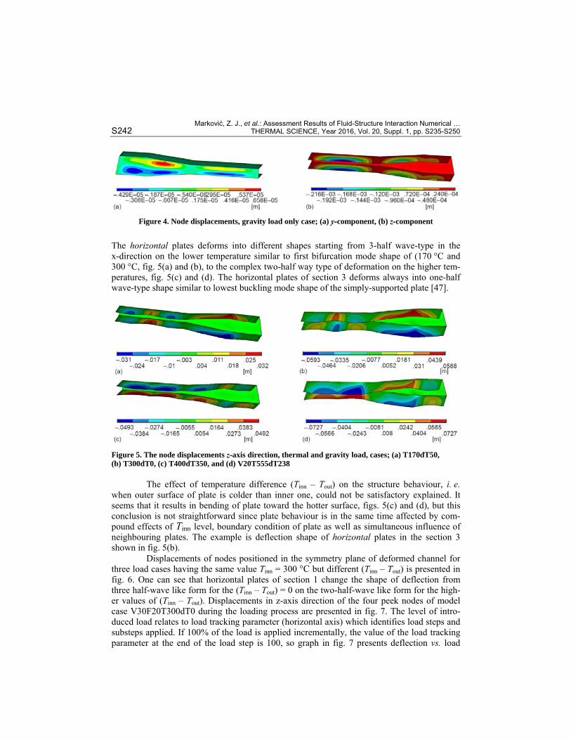
Results of numerical simulation of the structural model under gravity load only are presented in fig. 4. Gravity load on the middle-plane of horizontal plates is equal to Pg = tρg = 765 Pa, where t is the plate thickness, ρ – the density, and g – the gravity accelera-tion. The peak of bow shape of the horizontal plates in the section 1 reach 2% of the plate thickness, fig. 4(b). Transverse gravity load create bending moments along the edge of con-nections of vertical and horizontal plane inducing two-half-wave-type deformation of the ver-tical plates, fig. 4(a).
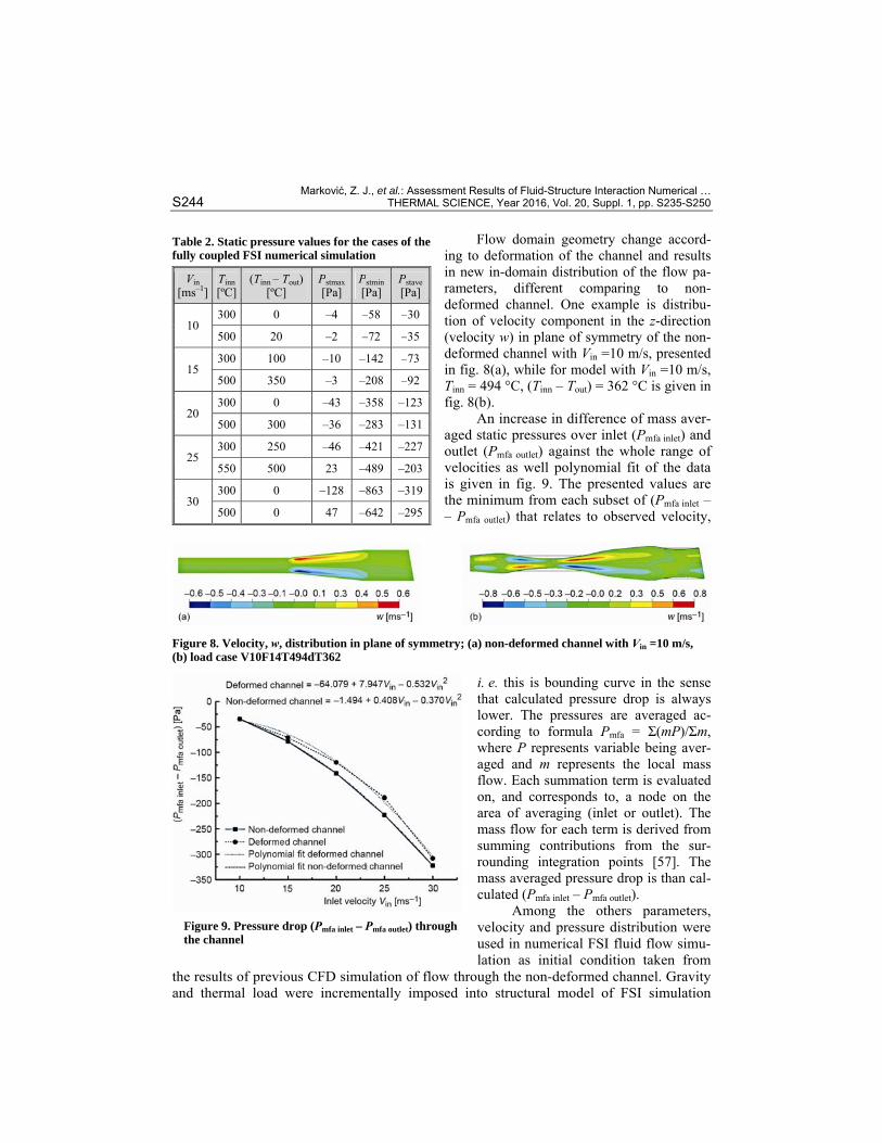
Results of numerical simulation of the structural model under thermal and gravity load only for four different loads cases defined by Tinn and (Tinn – Tout) are presented in fig. 5.
Marković, Z. J., et al.: Assessment Results of Fluid-Structure Interaction Numerical … S242 THERMAL SCIENCE, Year 2016, Vol. 20, Suppl. 1, pp. S235-S250
Figure 4. Node displacements, gravity load only case; (a) y-component, (b) z-component
The horizontal plates deforms into different shapes starting from 3-half wave-type in the x-direction on the lower temperature similar to first bifurcation mode shape of (170 °C and 300 °C, fig. 5(a) and (b), to the complex two-half way type of deformation on the higher tem-peratures, fig. 5(c) and (d). The horizontal plates of section 3 deforms always into one-half wave-type shape similar to lowest buckling mode shape of the simply-supported plate [47].
Figure 5. The node displacements z-axis direction, thermal and gravity load, cases; (a) T170dT50, (b) T300dT0, (c) T400dT350, and (d) V20T555dT238
The effect of temperature difference (Tinn – Tout) on the structure behaviour, i. e. when outer surface of plate is colder than inner one, could not be satisfactory explained. It seems that it results in bending of plate toward the hotter surface, figs. 5(c) and (d), but this conclusion is not straightforward since plate behaviour is in the same time affected by com-pound effects of Tinn level, boundary condition of plate as well as simultaneous influence of neighbouring plates. The example is deflection shape of horizontal plates in the section 3 shown in fig. 5(b).
Displacements of nodes positioned in the symmetry plane of deformed channel for three load cases having the same value Tinn = 300 °C but different (Tinn – Tout) is presented in fig. 6. One can see that horizontal plates of section 1 change the shape of deflection from three half-wave like form for the (Tinn – Tout) = 0 on the two-half-wave like form for the high-er values of (Tinn – Tout). Displacements in z-axis direction of the four peek nodes of model case V30F20T300dT0 during the loading process are presented in fig. 7. The level of intro-duced load relates to load tracking parameter (horizontal axis) which identifies load steps and substeps applied. If 100% of the load is applied incrementally, the value of the load tracking parameter at the end of the load step is 100, so graph in fig. 7 presents deflection vs. load

Marković, Z. J., et al.: Assessment Results of Fluid-Structure Interaction Numerical … THERMAL SCIENCE, Year 2016, Vol. 20, Suppl. 1, pp. S235-S250 S243
Figure 6. Displacement of the nodes in symmetry plane of deformed channel
curves for observed nodes. Peek nodes are lo-cated in the symmetry plane of upper plates and their position is marked in fig. 6. In this case, plates deforms in the three half-wave like shape similar to one presented in fig. 5(b).
Displacement notations are: UZ_Node 1 – displacement of the Node 1, tip point of the first (from left to right) half-wave of section 1 upper plate; UZ_Node 2 – displacement of the Node 2, tip point of the second half-wave, etc. Load – deflection curves shows no buckling. They follow stable, but softened non-linear behaviour typical to geometrically imperfect plate [47].
Results of numerical simulation for load case of fully developed flow through not de-formed channel, with no gravity and tempera-ture load, are presented in tab. 1. The value of maximal (Pstmax), minimal (Pstmin), and area av-eraged (Pstave) static pressure at the fluid-upper horizontal plate of the section 1 interface, fig. 1(a), is presented for different values of inlet velocity Vin. The value of Pstave is almost mean of the values Pstmax and Pstmin indicating close to uniform-type of static pressure distribution over the plate area. With the increase of Vin the value of Pstave increase up to the level of one half of Pg thus becoming a significant impact on formation of shapes in which plate deforms. The results of the fully coupled FSI numerical simulation of the pressure distribution over the same upper horizontal plate in the section 1 are present in tab. 2. As a consequence of the plate deflection, static pressure distribution over the interfacing surface between the structural and fluid model is highly non-uniform, locally reaching the values close to the gravity load.
Figure 7. Displacements of the peek nodes in z-direction during loading
Table 1. Static pressure values for the case of flow through no deformable channel
Vin [ms–1] Pstmax [Pa] Pstmin [Pa] Pstave [Pa] 10 –28 –41 –36 15 –65 –93 –83 20 –132 –166 –148 25 –207 –260 –252 30 –298 –375 –336
Marković, Z. J., et al.: Assessment Results of Fluid-Structure Interaction Numerical … S244 THERMAL SCIENCE, Year 2016, Vol. 20, Suppl. 1, pp. S235-S250
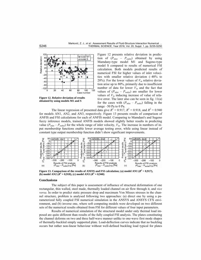
Flow domain geometry change accord-ing to deformation of the channel and results in new in-domain distribution of the flow pa-rameters, different comparing to non-deformed channel. One example is distribu-tion of velocity component in the z-direction (velocity w) in plane of symmetry of the non-deformed channel with Vin =10 m/s, presented in fig. 8(a), while for model with Vin =10 m/s, Tinn = 494 °C, (Tinn – Tout) = 362 °C is given in fig. 8(b).
An increase in difference of mass aver-aged static pressures over inlet (Pmfa inlet) and outlet (Pmfa outlet) against the whole range of velocities as well polynomial fit of the data is given in fig. 9. The presented values are the minimum from each subset of (Pmfa inlet – – Pmfa outlet) that relates to observed velocity,
Figure 8. Velocity, w, distribution in plane of symmetry; (a) non-deformed channel with Vin =10 m/s, (b) load case V10F14T494dT362
i. e. this is bounding curve in the sense that calculated pressure drop is always lower. The pressures are averaged ac-cording to formula Pmfa = Σ(mP)/Σm, where P represents variable being aver-aged and m represents the local mass flow. Each summation term is evaluated on, and corresponds to, a node on the area of averaging (inlet or outlet). The mass flow for each term is derived from summing contributions from the sur-rounding integration points [57]. The mass averaged pressure drop is than cal-culated (Pmfa inlet – Pmfa outlet).
Among the others parameters, velocity and pressure distribution were used in numerical FSI fluid flow simu-lation as initial condition taken from
the results of previous CFD simulation of flow through the non-deformed channel. Gravity and thermal load were incrementally imposed into structural model of FSI simulation
Table 2. Static pressure values for the cases of the fully coupled FSI numerical simulation
Vin [ms–1]
Tinn [ºC]
(Tinn – Tout) [ºC]
Pstmax [Pa]
Pstmin[Pa]
Pstave[Pa]
10 300 0 –4 –58 –30
500 20 –2 –72 –35
15 300 100 –10 –142 –73
500 350 –3 –208 –92
20 300 0 –43 –358 –123
500 300 –36 –283 –131
25 300 250 –46 –421 –227
550 500 23 –489 –203
30 300 0 –128 –863 –319
500 0 47 –642 –295
Figure 9. Pressure drop (Pmfa inlet – Pmfa outlet) through the channel

Marković, Z. J., et al.: Assessment Results of Fluid-Structure Interaction Numerical … THERMAL SCIENCE, Year 2016, Vol. 20, Suppl. 1, pp. S235-S250 S245
through load step sequence. Since both CFD and CSD solvers exchange values of loads and displacements calculated until the time point wen exchange take place, additional in-vestigation should be done in order to check the influence of the order and manner of load-ing on the final results of FSI simulation [25, 26, 47].
Results of FSI calculated pressure drop (Pinlet – Poutlet)FSI, as well as results of calcu-lation of Mamdany’s fuzzy inference model M2 output parameter for the input velocity of Vin = 30 m/s are presented in fig. 10(a). The results of calculation of maximal values of Von Misses stresses in the deformed structure, σVMFSImax, for the case of input velocity of Vin = 30 m/s and prediction of σVMFISmax by using model M3 are presented in fig. 10(b).
Figure 10. Performances of FIS models in prediction of the results of FSI simulation; (a) model M2, (b) model M3, (c) relative deviation of results for models M2 and M3
Relative deviations of results predicted using model M2 and model M3, compared to
results of FSI numerical simulation, are presented in fig. 10(c). The bounding values of the relative deviation are –13.8...14.3% for (Pinlet – Poutlet), and –12.5...12.5% for σVMmax. Al-though results indicate that prediction of values σVMmax seems a little bit poor, the trend of ANSYS structural computation is followed. As pointed in [36] the reasons for this could be found in the fact that stress distribution is highly non-linear. Additional reason is the pressure driven half-wave-like-shape deformation of the channel plates which determine position where σVMmax appear. This is in the accordance with the conclusion given in [36] since sharp change in the stress values is strongly related to the position of the σVMmax appearance namely on the shape of deflection and boundary condition. Comparing the results of FSI and FIS we see that parameter (Pinlet – Poutlet) has been calculated with smaller deviation, with linear regression of presented data giving R2 = 0.939 for model M1 and R2 = 0.901 for model M2. In the case of parameter σVMmax a larger deviation is observed, and value of R2 = 0.624 is obtained (fig. 11).
Figure 11. Comparison of the results of FIS and FSI calculation; (a) model M1 (R2 = 0,939), (b) model M2 (R2 = 0,901), (c) model M3 (R2 = 0,624)
Marković, Z. J., et al.: Assessment Results of Fluid-Structure Interaction Numerical … S246 THERMAL SCIENCE, Year 2016, Vol. 20, Suppl. 1, pp. S235-S250
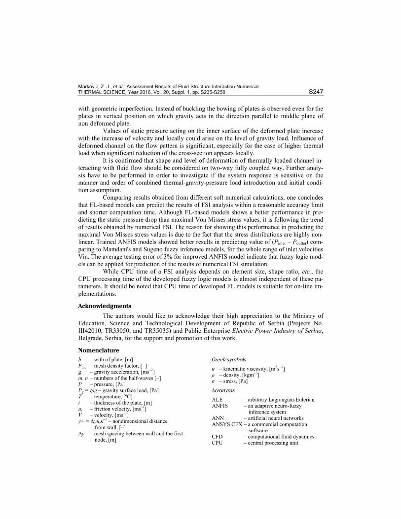
Figure 12 presents relative deviation in predic-tion of (Pinlet – Poutlet) obtained by using Mamdany-type model M1 and Sugeno-type model S compared to results of numerical FSI calculation. Both models predicted results of numerical FSI for higher values of inlet veloci-ties with smaller relative deviation (–40% to 20%). For the lower values of Vin relative devia-tion arise up to 80%, primarily due to insufficient number of data for lower Vin and the fact that values of (Pinlet – Poutlet) are smaller for lower values of Vin inducing increase of value of rela-tive error. The later also can be seen in fig. 11(a) for the cases with (Pinlet – Poutlet) falling in the range –50 Pa to 0 Pa.
The linear regression of presented data give R2 = 0.917, R2 = 0.918, and R2 = 0.940 for models AN1, AN2, and AN3, respectively. Figure 13 presents results of comparison of ANFIS and FSI calculations for each of ANFIS model. Comparing to Mamdani's and Sugeno fuzzy inference models, trained ANFIS models showed slightly better results in predicting value (Pinlet – Poutlet) for the whole range of inlet velocity, Vin. The increase in numbers of in-put membership functions enable lower average testing error, while using linear instead of constant type output membership function didn’t show significant improvements.
Figure 13. Comparison of the results of ANFIS and FSI calculation; (a) model AN1 (R2 = 0,917), (b) model AN2 (R2 = 0,918), (c) model AN3 (R2 = 0,940)
Conclusions
The subject of this paper is assessment of influence of structural deformation of one rectangular, thin walled, steel made, thermally loaded channel on air flow through it, and vice versa. In order to predict static pressure drop and maximum Von Misses stresses in the chan-nel structure, problem is analysed following two approaches: (a) direct one by using a pa-rameterized fully coupled FSI numerical simulation in the ANSYS and ANSYS CFX envi-ronment, and (b) inverse one, where soft computing models were developed on two different sets of the numerical results obtained from FSI for different values of four input parameters.
Results of numerical simulation of the structural model under only thermal load im-posed are quite different than results of the fully coupled FSI analysis. The plates constituting the channel deforms on two and three half-wave manner unlike to one-wave first mode shapes of thermally-buckled simply supported plate. Load-deflection curves indicate that no buckling occurs but rather non-linear behaviour without well-defined buckling load typical for plates
Figure 12. Relative deviation of results obtained by using models M1 and S
Marković, Z. J., et al.: Assessment Results of Fluid-Structure Interaction Numerical … THERMAL SCIENCE, Year 2016, Vol. 20, Suppl. 1, pp. S235-S250 S247
with geometric imperfection. Instead of buckling the bowing of plates is observed even for the plates in vertical position on which gravity acts in the direction parallel to middle plane of non-deformed plate.
Values of static pressure acting on the inner surface of the deformed plate increase with the increase of velocity and locally could arise on the level of gravity load. Influence of deformed channel on the flow pattern is significant, especially for the case of higher thermal load when significant reduction of the cross-section appears locally.
It is confirmed that shape and level of deformation of thermally loaded channel in-teracting with fluid flow should be considered on two-way fully coupled way. Further analy-sis have to be performed in order to investigate if the system response is sensitive on the manner and order of combined thermal-gravity-pressure load introduction and initial condi-tion assumption.
Comparing results obtained from different soft numerical calculations, one concludes that FL-based models can predict the results of FSI analysis within a reasonable accuracy limit and shorter computation time. Although FL-based models shows a better performance in pre-dicting the static pressure drop than maximal Von Misses stress values, it is following the trend of results obtained by numerical FSI. The reason for showing this performance in predicting the maximal Von Misses stress values is due to the fact that the stress distributions are highly non-linear. Trained ANFIS models showed better results in predicting value of (Pinlet – Poutlet) com-paring to Mamdani's and Sugeno fuzzy inference models, for the whole range of inlet velocities Vin. The average testing error of 3% for improved ANFIS model indicate that fuzzy logic mod-els can be applied for prediction of the results of numerical FSI simulation.
While CPU time of a FSI analysis depends on element size, shape ratio, etc., the CPU processing time of the developed fuzzy logic models is almost independent of these pa-rameters. It should be noted that CPU time of developed FL models is suitable for on-line im-plementations.
Acknowledgments
The authors would like to acknowledge their high appreciation to the Ministry of Education, Science and Technological Development of Republic of Serbia (Projects No. III42010, TR33050, and TR35035) and Public Enterprise Electric Power Industry of Serbia, Belgrade, Serbia, for the support and promotion of this work.
Nomenclature b – with of plate, [m] Fmd – mesh density factor, [–] g – gravity acceleration, [ms–2] m, n – numbers of the half-waves [–] P – pressure, [Pa] Pg = tρg – gravity surface load, [Pa] T – temperature, [ºC] t – thickness of the plate, [m] uτ – friction velocity, [ms–1] V – velocity, [ms–1] y+ = ∆yuτκ–1 – nondimensional distance
from wall, [–] ∆y – mesh spacing between wall and the first
node, [m]
Greek symbols
κ – kinematic viscosity, [m2s–1] ρ – density, [kgm–3] σ – stress, [Pa]
Acronyms
ALE – arbitrary Lagrangian-Eulerian ANFIS – an adaptive neuro-fuzzy
inference system ANN – artificial neural networks ANSYS CFX – a commercial computation
software CFD – computational fluid dynamics CPU – central processing unit
Marković, Z. J., et al.: Assessment Results of Fluid-Structure Interaction Numerical … S248 THERMAL SCIENCE, Year 2016, Vol. 20, Suppl. 1, pp. S235-S250
CSD – computational structural and solid dynamics
CSM – computational structural mechanics ES – expert system FE – finite element FEM – finite element method FIS – fuzzy inference system FL – fuzzy logic FSI – fluid-structure interaction KB – knowledge base
NN – neural networks SST – shear stress transport turbulence
Subscripts
in – inlet inn – inner mfa – mass averaged value out – outer VMmax – maximal Von Misses stress [Pa]
References [1] Frandsen, J. B., Numerical Bridge Deck Studies Using Finite Elements. Part I: Flutter, Journal of Fluids
and Structures, 19 (2004), 2, pp. 171-191 [2] Eloy, C., et al., Aeroelastic Instability of Cantilevered Flexible Plates in Uniform Flow, J. Fluid Mech.,
611 (2008), Sep., pp. 97-106 [3] Gordnier, R. E., Visbal, M. R., Computation of the Aeroelastic Response of a Flexible Delta Wing at
High Angles of Attack, Journal of Fluids and Structures, 19 (2004), 6, pp. 785-800 [4] Farhat, C., et al., Application of a Three-Field Non-Linear Fluid–Structure Formulation to the Prediction
of the Aeroelastic Parameters of an F-16 Fighter, Computers & Fluids 32 (2003), 1, pp. 3-29 [5] Benkherouf, T., et al., Efficiency of an Auto-Propelled Flapping Airfoil, Journal of Fluids and Struc-
tures, 27 (2011), 4, pp. 552-566 [6] Ducoin, A., et al., An Experimental and Numerical Study of the Hydroelastic Behaviour of an Hydrofoil
in Transient Pitching Motion, Proceedings, 1st International Symposium on Marine Propulsors SMP’09, Trondheim, Norway, 2009
[7] Munch, C., et al., Fluid–Structure Coupling for an Oscillating Hydrofoil, Journal of Fluids and Struc-tures, 26 (2010), 6, pp. 1018-1033
[8] Esmailzadeh, M., et al., Three-Dimensional Modelling of Curved Structures Containing and/or Sub-merged in Fluid, Finite Elements in Analysis and Design, 44 (2008), 6-7, pp. 334-345
[9] Gluck M., et al., Computation of Fluid–Structure Interaction on Lightweight Structures, Journal of Wind Engineering and Industrial Aerodynamics, 89 (2001), 14-15, pp. 1351-1368
[10] Fairuz, Z. M., et al., Fluid Structure Interaction of Unsteady Aerodynamics of Flapping Wing at Low Reynolds Number, Engineering Applications of Computer Fluid Mechanic, 7 (2013), 1, pp. 144-158
[11] Kuntz, M., Menter, F. R., Simulation of Fluid-Structure Interactions in Aeronautical Applications, Pro-ceedings, European Congress on Computational Methods in Applied Sciences and Engineering, ECCOMAS 2004, Jyvaskyla, Finland, 2004
[12] Attar, P. J., Gordnier, R. E., Aeroelastic Prediction of the Limit Cycle Oscillations of a Cropped Delta Wing, Journal of Fluids and Structures, 22 (2006), 1, pp. 45-58
[13] Fairuz, Z. M., et al., Effect of Wing Deformation on the Aerodynamic Performance of Flapping Wings: Fluid-Structure Interaction Approach, J. Aerosp. Eng., 1 (2016), 04016006
[14] Fairuz, Z. M., et al., Fluid Structure Interaction of Unsteady Aerodynamics of Flapping Wing at Low Reynolds Number, Engineering Applications of Computer Fluid Mechanic, 7 (2013), 1, pp. 144-158
[15] Dowell, E. H., Hall, K. C., Modelling of Fluid–Structure Interaction, Annual Review of Fluid Mechanics 33, (2001), Jan., pp. 445-490
[16] Doare, O., et al., Flutter of an Elastic Plate in a Channel Flow: Confinement and Finite-Size Effects, J. Fluids Struct., 27 (2011), 1, pp. 76-88
[17] Kirpekara, S., Bogy, D. B., Computing the Aeroelastic Disk Vibrations in a Hard Disk Drive, Journal of Fluids and Structures, 24 (2008), 1, pp. 75-95
[18] Au-Yang, M. K., Galford, J. E., Fluid – Structure Interaction – A Survey with Emphasis on its Applica-tion to Nuclear Steam System Design, Nuclear Engineering and Design, 70 (1982), 3, pp. 387-399
[19] Schumann, U., Impacts and Fluid-Structure Interaction in Pressurized Water Reactor Safety Analysis, Nuclear Engineering and Design, 69 (1982), May, pp. 313-326
[20] Borazjani, I., Fluid–Structure Interaction, Immersed Boundary-Finite Element Method Simulations of Bio-Prosthetic Heart Valves, Comput. Methods Appl. Mech. Engrg., 257, (2013), Apr., pp. 103-116

Marković, Z. J., et al.: Assessment Results of Fluid-Structure Interaction Numerical … THERMAL SCIENCE, Year 2016, Vol. 20, Suppl. 1, pp. S235-S250 S249
[21] Choulya, F., et al., Numerical and Experimental Study of Expiratory Flow in the Case of Major upper Airway Obstructions with Fluid–Structure Interaction, Journal of Fluids and Structures, 24, (2008), 2, pp. 250-269
[22] Hasnedlova, J., et al., Numerical Simulation of Fluid–Structure Interaction of Compressible Flow and Elastic Structure, Computing, 95 (2013), 1, pp 343-361
[23] Barone, M. F., Payne, J. L., Methods for Simulation-Based Analysis of Fluid-Structure Interaction, Re-port SAND2005-6573, Sandia National Laboratories, Albuquerque, N. Mex., USA, 2005
[24] Sigrist, J. F., Garreau, S., Dynamic Analysis of Fluid-Structure Interaction Problems with Modal Meth-ods Using Pressure-Based Fluid Finite Elements, Finite Elements in Analysis and Design, 43 (2007), 4, pp. 287-300
[25] Culler, A. J., McNamara, J. J., Studies on Fluid-Thermal-Structural Coupling for Aerothermoelasticity in Hypersonic Flow, AIAA Journal, 48 (2010), 8, pp. 1721-1738
[26] Shengze, L., et al., Fluid-Thermal-Structure Coupled Analysis of Grid Fins for Hypersonic Flight Vehi-cle, Proceedings, Coupled Problems 2015, VI International Conference on Computational Methods for Coupled Problems in Science and Engineering, San Servolo, Venice, Italy, 2015, pp. 701-712
[27] Zhao, X., et al., Coupled Flow-Thermal-Structural Analysis of Hypersonic Aerodinamically Heated Cy-lindrical Leading Edge, Engineering Applications of Computational Fluid Mechanics, 5 (2011), 2, pp. 170-179
[28] Guo, C. Q., Paidoussis, M. P., Stability of Rectangular Plates with Free Side-Edges in Two-Dimensional Inviscid Channel Flow, J Appl Mech, 67 (2000), 1, pp. 171-176
[29] Kortesis, S., Panagiotopoulos, P. D., Neural Networks for Computing in Structural Analysis: Methods and Prospects of Applications, International Journal for Numerical Methods in Engineering, 36 (1993), 13, pp. 2305-2318
[30] Szewczyk, Z. P., Noor, A. K., A Hybrid Neurocomputing/Numerical Strategy for Non-linear Structural Analysis, Compurers & Structures, 58 (1996), 4, pp. 661-677
[31] Liu, S. W., et al., Detection of Cracks Using Neural Networks and Computational Mechanics, Comp. Methods Appl. Mech.Engrg., 191, (2002), 25-26, pp. 2831-2845
[32] Baghalian, S., et al., Closed-Form Solution for Flow Field in Curved Channels in Comparison with Ex-perimental and Numerical Analyses and Artificial Neural Network, Engineering Applications of Compu-tational Fluid Mechanics, 6 (2012), 4, pp. 514-526
[33] Erdik, T., et al., Artificial Neural Networks for Predicting Maximum Wave Runup on Rubble Mound Structures, Expert Systems with Applications, 36 (2009), 3, pp. 6403-6408
[34] Yari, E., et al., Applying the Artificial Neural Network to Estimate the Drag Force for an Autonomous Underwater Vehicle, Open Journal of Fluid Dynamics, 4 (2014), 3, pp. 334-346
[35] Zadeh, L. A., Fuzzy Sets, Information and Control, 8 (1965), 3, pp. 338-353 [36] Rao, A. V. S., Pratihar, D. K., Fuzzy Logic-Based Expert System to Predict the Results of Finite Ele-
ment Analysis, Knowledge-Based Systems, 20 (2007), 1, pp. 37-50 [37] Hossain, A., et al., Prediction of Aerodynamic Characteristics of an Aircraft Model with and without
Winglet Using Fuzzy Logic Technique, Aerospace Science and Technology, 15 (2011), 8, pp. 595-605 [38] Mamdani, E. H., Assilian, S., An Experiment in Linguistic Synthesis with a Fuzzy Logic Controller, In-
ternational Journal of Man-Machine Studies, 7 (1975), 1, pp. 1-13 [39] Erdik, T., Fuzzy Logic Approach to Conventional Rubble Mound Structures Design, Expert Systems
with Applications, 36 (2009), 3, pp. 4162-4170 [40] Raja, A. S., Arasu, A. V., Prediction of Cold Start Hydrocarbon Emissions of Air Cooled Two Wheeler
Spark Ignition Engines by Simple Fuzzy Logic Simulation, Thermal Science, 18 (2014), 1, pp. 179-191 [41] Takagi, T., Sugeno, M., Fuzzy Identification of Systems and its Applications to Modelling and Control,
Proceedings, IEEE Transaction on Systems, Man and Cybernetics, 1985, vol. SMC-15, no. 1, pp. 116-132 [42] Vassilopoulos, A. P., Bedi, R., Adaptive Neuro-Fuzzy Inference System in Modelling Fatigue Life of
Multidirectional Composite Laminate, Computational Materials Science, 43 (2008), 4, pp. 1086-1093 [43] Ćirić, I. T., et al., Air Quality Estimation by Computational Intelligence Methodologies, Thermal Sci-
ence, 16 (2012), Suppl. 2, pp. S493-S504 [44] Saeed, R. A., et al., 3D Fluid–Structure Modelling and Vibration Analysis for Fault Diagnosis of Francis
Turbine Using Multiple ANN and Multiple ANFIS, Mechanical Systems and Signal Processing, 34 (2013), 1-2, pp. 259-276
Marković, Z. J., et al.: Assessment Results of Fluid-Structure Interaction Numerical … S250 THERMAL SCIENCE, Year 2016, Vol. 20, Suppl. 1, pp. S235-S250
[45] Stefanović, P., et. al., Working Conditions Analysis of One Burner Chanell for the Pulverized Coal Plasmachemical Preparation for Stabilization of Combustion Process in Unit A1Boiler, TPP TENT, Obrenovac, Serbia, Report NIV-ITE 413, Vinca Institute of Nuclear Sciences, Belgrade, 2011
[46] Stefanović, P., et al., Numerical Simulation of Pulverized Kolubara Lignite Plasma Chemical Gasifica-tion, Proceedings, International Conference on Physics of Low Temperature Plasma PLTP-03, Navchalna Knyga, Kiev, 2004, pp. 3-27-31-p
[47] Robert, J. M., Buckling of Bars, Plates and Shells, Bull Ridge Publishing, Blacksburg, Va., USA, 2006 [48] Hyghes, T. J. R., Numerical Implementation of Constitutive Models: Rate-Independent Deviatoric Plas-
ticity, in: Theoretical Foundation for Large-Scale Computations for Non-Linear Material Behavior, Martinus Nijhoff Publishers, Dordrecht, The Netherlands, 1984
[49] ***, ANSYS Release 12.0 Documentation for ANSYS, ANSYS Inc., 2009 [50] Menter, F. R., Two-Equation Eddy-Viscosity Turbulence Models for Engineering Application, AIAA
Journal, 32 (1994), 8, pp. 1598-1605 [51] Bardina, J. E., et al., Turbulence Modeling, Validation, Testing and Development, NASA Technical
Memorandum 110446, 1997 [52] Wilcox, D., Comparison of Two-Equation Turbulence Models for Boundary Layers with Pressure Gra-
dient, AIAA Journal, 31 (1993), 8, pp. 1414-1421 [53] Launder, B. E., Spalding, D. B., The Numerical Computation of Turbulent Flows, Computer Methods in
Applied Mechanics and Engineering, 3 (1974), 2, pp. 269-289 [54] Raw, M. J., Robustness of Coupled Algebraic Multigrid for the Navier-Stokes Equations, AIAA 96-
0297, Proceedings, 34th Aerospace and Sciences Meeting & Exhibit, Reno, Nev., USA, 1996 [55] Demirdzic, I., Peric, M., Space Conservation Law in Finite Volume Calculations of Fluid Flow, Int. J.
Num. Methods in Fluids, 8 (1998), Sep., pp. 1037-1050 [56] Donea, J., et al., An Arbitrary Lagrangian–Eulerian Finite Element Method for Transient Dynamic Fluid
– Structure Interactions, Comput. Methods Appl. Mech. Eng., 33 (1982), 1-3, pp. 689-723 [57] ***, ANSYS CFX-Solver Theory Guide, Release 12.1, Ansys Inc., 2009 [58] ***, The Language of Technical Computing, MATLAB, Math Works Inc., 2012
Paper submitted: January 16, 2016 Paper revised: March 20, 2016 Paper accepted: April 10, 2016