assessment of the bond behaviour of nsm frp materials by pullout...
TRANSCRIPT

- 1 -
Abstract of Paper No: 197
Assessment of the bond behaviour of NSM FRP materials by pullout tests
Inês Costa
University of Minho, Guimarães, Portugal Joaquim Barros
University of Minho, Guimarães, Portugal
Pullout tests are often used to determine the optimal bond length (Le) between Fibre Reinforced Polymers (FRP) and Reinforced Concrete (RC). Using the results of these tests, the Le and the local bond stress-slip relationship have also been obtained by performing inverse analysis with FEM-based numerical tools and analytical models. The Le parameter and the local bond stress-slip relationship participate in some design guidelines in the context of structural strengthening with FRP systems, and, therefore, their rigorous assessment is a target of high relevance. In terms of its assessment by performing pullout tests, some test setups were analyzed in the present work: i) Single-Shear Pushing; ii) Double-Shear Pulling and iii) Beam Bending Test. Taking into account the data registered in the sensors used in these tests and the failure modes occurred, a critical analysis is done in terms of the reliability of these tests to reproduce the bond phenomena occurred in a real FRP strengthened RC structure. This critical analysis is based on a recent large Round Robin Test program with several Near Surface Mounted (NSM) FRP systems carried out at the University of Minho, and also taking into account the results obtained in pullout tests executed in previous research programs. The final purpose of the present work is advance with recommendations about the most appropriate test setup for the characterization of the NSM-concrete bond behaviour.
Corresponding authors email: [email protected], [email protected]

- 2 -
Assessment of the bond behaviour of NSM FRP materials by pullout tests
Inês Costa1 and Joaquim Barros2 1 University of Minho, Guimarães, Portugal 2 University of Minho, Guimarães, Portugal
ABSTRACT: Pullout tests are often used to determine the optimal bond length (Le) between Fibre Reinforced Polymers (FRP) and Reinforced Concrete (RC). Using the results of these tests, the Le and the local bond stress-slip relationship have also been obtained by performing inverse analysis with FEM-based numerical tools and analytical models. The Le parameter and the local bond stress-slip relationship participate in some design guidelines in the context of structural strengthening with FRP systems, and, therefore, their rigorous assessment is a target of high relevance. In this context, in the present work three types of bond tests are analysed to highlight their positive and negative aspects, and to recommend the most appropriate test setup for the bond characterization in terms of NSM flexural and shear strengthening.
1 INTRODUCTION
The effectiveness of the Near Surface Mounted (NSM) technique for the flexural and shear strengthening is already well proved (Barros & Fortes 2005, Dias & Barros 2010) and is a competitive alternative to Externally Bonded Reinforcement (EBR) in the structural rehabilitation. According to the NSM technique, Fibre Reinforced Polymers (FRP) bars are installed into grooves opened on the concrete cover of Reinforced Concrete (RC) elements. Likewise in ordinary reinforcing steel, a sufficient anchorage length must be provided, in order to allow the full mobilization of the FRP material. This minimum anchorage length, herein referred as optimal bond length (Le), is usually determined via pullout tests.
Some of the most common types of pullout test setups available were formerly grouped by Chen et al. (2001) for EBR, in the following general categories: Single/Double-Shear Pushing Test, Single/Double-Shear Pulling Test and Beam Bending Test. Usually, in all these tests the loaded-end slip (sl) and the corresponding force (F) are measured. In some tests the free-end slip (sf) is also measured, as well as the strains in some selected sections of the FRP. From the obtained data in terms of F, sl and sf, and performing inverse analysis with numerical (Sena-Cruz & Barros 2004a) or analytical models (Sena-Cruz & Barros 2004b) the local bond-slip law, τ – s, can be obtained. However, this law can only represent the FRP-concrete interface if the bond test simulates closely the real bond conditions found in real strengthening applications. Based on experimental programs recently carried out with three types of bond tests, a critical analysis is performed in the present work in order to recommend the most appropriate for NSM flexural and shear strengthening assessment. The following bond test setups are analyzed: Single-Shear Pushing Test, performed by Macedo et al. (2008); Double-Shear Pulling Test, carried out in the scope of an International Round Robin Test (Costa & Barros 2010) and Beam Bending Test executed by Sena-Cruz et al. (2006).

- 3 -
2 TEST SETUPS AND MONITORING SYSTEMS
2.1 Single-Shear Pushing Test (SSPT)
SSPT was executed by Macedo et al. (2008) using the setup depicted in Figure 1a. This type of setup is designated as “pushing test” because the load applied in the FRP is balanced by a compressive reaction on the top of the concrete block. The original aim of this test program was to assess the influence of the depth of installation of the CFRP laminate (y in Figure 1a). From these tests the force-slip relationship for several bond length values were obtained (Lb = 40, 70, 90, 120 and 150 mm) as well as for three different depths of installation (y = 0, 6 and 12 mm), Figure 1.
The displacement transducers used measured the loaded-end slip (LVDT1) and the free-end slip (LVDT 2). A steel piece (SP1) was fastened around the CFRP on the top (z = 0 mm) and LVDT1 was connected to a metallic accessory (SP2) glued on the concrete’s surface, 75 mm from the top surface of the concrete specimen, where the concrete deformability is assumed negligible (Figure 1b). In this way, LVDT1 measures the relative displacement between the top zone (FRP), and the concrete block, at the level were the Lb starts. The free-end slip was measured by a LVDT fixed in a steel piece glued in a concrete zone of negligible deformation (about 50 mm below the bottom extremity of the bond length), which records the displacement of a steel piece fastened to the CFRP laminate, some millimetres below the bottom extremity of the bond length (Figure 1b). To accurately determine the loaded-end slip, the deformation of the laminate in the L0 length (Figure 1a) should be removed from the readings recorded in the LVDT1.
(a)
450
F
75
75
Lb
150
150
5
22
1.4
10y
LVDT1
z L0
LVDT 2
(b)
Figure 1. Single-Shear Pushing Test setup: (a) Specimen configuration and dimensions; (b) Detail of the loaded and free-end slip measurements. (Dimensions in mm)
2.2 Double-Shear Pulling Test (DSPT)
DSPT was carried out in the scope of an International Round Robin Test, and is labelled as “pulling” because the two blocks that form the DSPT specimen, depicted in Figure 2, are pulled away from each other in order to stress the FRP. The test is controlled by the relative movement between the faces of the two blocks, and this movement was measured by LVDT1, which is the internal LVDT of the testing machine. Using the setup schematically represented in Figure 2a it

- 4 -
is only possible to measure the loaded-end slip (LVDTs 2 and 3), since the available space in the free end zone is too short for the installation of a LVDT. In this experimental program strains were also recorded along the smallest bond length (Lb = 300 mm) through strain gauges placed 10, 80 and 220 mm from the loaded-end (Figure 2a). The two FRP laminates were expected to be stressed simultaneously and to fail on the smallest bond length.
(a)
50
Steel Rebars
50
Steel Rebars
F
F
50
350
SG220
SG80
SG10
LVDT2
LVDT 3
(LVDT )1
1510
5
1.4
150
50
2φ16
80
140
7010
300
50 50
z
(b)
Figure 2. Double-Shear Pulling Test setup: (a) Specimen configuration and dimensions; (b) Detail of the loaded-end slip measurement. (Dimensions in mm)
Small tabs were glued in the FRP’s loaded-end, making an angle of 90º with the FRP and creating an extension outside the slit. A steel piece was fastened in that tab providing the conditions for the measurement of the FRP loaded-end slip by LVDTs 2 and 3 supported near the extremity of the concrete block (see Figure 2b).
This setup is surely the most appropriate to simulate the contribution of a NSM FRP element when applied as shear reinforcement. De Lorenzis et al. (2002) described this type of double tests less accurate to determine the local stress-slip relationship because any eccentricity could provoke undesired flexural effects and, therefore, interfere with the results. In reality, the experimental tests carried out showed that undesired eccentricities are difficult to circumvent making the analysis of the results less obvious.
2.3 Beam Bending Test (BBT)
Similar to the SSPT, the Beam Bending Test (Figure 3) provides also the loaded- and the free-end slips (LVDT2 and LVDT1 respectively). Although this type of tests implies additional care while handling and placing the specimens, because there is a risk of damaging the FRP in the absence of a permanent hinge connecting the blocks, no special grips or complex supports are

- 5 -
needed. Moreover, the number of FRPs applied and its spacing can also be studied, using the same setup and laboratory resources.
(a)
F2
F2
75 150 50 50 50 150 75
22530
150
40
SG
LVDT1
LVDT2
Lb
150
75 75
10 15
5
1.4
z
(b)
Figure 3. Beam Bending Test setup: (a) Specimen configuration and dimensions; (b) Detail of the loaded and free-end slip measurements. (Dimensions in mm)
Concrete blocks are connected by a steel hinge at mid-span, on the top, and by the CFRP laminate bonded in the bottom face. The monitoring system in these tests is similar to the one described for SSPT. A tab device similar to the one described for the DSPT is used for measuring the slip at the loaded end (Figure 3b). To directly assess the stress installed in the FRP, a strain gauge (SG) was positioned in the central zone of the FRP.
2.4 Comparison between setups using Finite Elements Analysis
As the name of the tests implies, Beam Bending Tests are more suitable to determine the local bond law and the optimal bond length in bending, while Shear and Double Shear Tests are more appropriate for the assessment of the optimal bond length in shear. Performing Finite Element (FE) Analysis, the experimental tests carried out were simulated numerically with the FEMIX computer program, and the deformed meshes included in Figure 4 were obtained. All the models simulated have the same Lb (120 mm), FRP cross section (1.4×10mm2), and the same geometry of the slit (5×22mm2). The intervening materials were in all cases modeled as solid 8-nodes FE with linear elastic isotropic behavior and, therefore, neglecting the existence of any non-linear surface between materials.
(a) (b)
(c)
Figure 4. Deformed meshes and correspondent displacement magnification factors: (a) SSPT, 100:1; (b) BBT, 10:1; (c) DSPT, 10:1.

- 6 -
0 20 40 60 80 100 1200
2
4
6
8
10
0 5 106
8
10
SSPT (Out) SSPT (In) DSPT (Out) DSPT (In) BBT (Out) BBT (In)
Long
itudi
nal
Str
ain
[‰]
xb [mm]
(a)
0 1 2In
0
10
Out
Hei
ght o
f the
FR
P
FRP displacement [mm]
εf = 10‰
SSPT DSPT BBT
(b)
Figure 5. Results from linear analysis: (a) Longitudinal strain along the bond length; (b) FRP displacement along the depth of the FRP cross section.
The FRP’s cross section was discretized with two brick elements along the height. For the analysis of the obtained results, the finite element nearest to the surface of the specimen is designated as “Out”, while the element deeper in groove is referred as “In”. As it can be seen, the deformation of the FRP is substantially different in the analyzed bond test setups, especially when shear and bending tests are compared. It should be noted the in-plane rotation of the CFRP laminate in the SSPT (Figure 4a), with the loaded-end having a downward movement and the free-end an upward movement, which was also registered in the experimental tests. This effect, however, did not occur in the DSPT due to the restriction offered by the larger bond length in the block for the anchorage of the CFRP (Figure 4c). In the BBT, the FRP has bended in turn of its highest inertia axis, introducing a gradient of strains and stresses along the depth of the cross section. This is quite visible in Figure 5a where the longitudinal strain in the FRP is plotted along the bond length (xb = 0 corresponds to the loaded end and xb = Lb corresponds to the free-end). In fact, when the maximum strain in the FRP is 10‰ (note that in SSPT and DSPT the strain profile along the height is almost equal), the maximum strain in the inner surface of the FRP in BBT is 1.5‰ smaller. This difference is too high to be neglected. Furthermore, the FRP bar considered in this study has a cross section height of 10 mm, meaning that this disparity of values will increase even more when the NSM technique is applied with FRP elements of deeper cross section. This gradient of strains and, consequently, the significant variation of stresses along the depth of the FRP cross section is representative of what happens when using NSM-FRP bars for the flexural strengthening, but does not replicate the gradient of stresses when NSM-FRP bars are used for the shear strengthening of RC beams. Figure 5b represents the variation of the loaded end slip along the depth of the FRP cross section when the maximum strain in the models was 10‰, from which it is visible the curvature occurred in the FRP in the BBT. The sl values are constant in the cross section depth and are almost equal for the SSPT and DSPT, but quite smaller than the sl values for the BBT.
3 EXPERIMENTAL PROGRAM
3.1 Properties of the materials
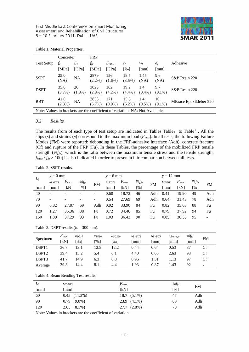
The main properties of the intervening materials are included in Table 1. The adhesives used the tests were those recommended by the FRP supplier, and had similar mechanical properties.
- 7 -
Table 1. Material Properties.
Test Setup
Concrete: FRP
Adhesive fc Ec ffu Ef,ISO εf wf df
[MPa] [GPa] [MPa] [GPa] [‰] [mm] [mm]
SSPT 25.0 (NA)
NA 2879 (2.2%)
156 (1.6%)
18.5 (3.5%)
1.45 (NA)
9.6 (NA)
S&P Resin 220
DSPT 35.0 (3.7%)
26 (1.8%)
3023 (2.3%)
162 (4.2%)
19.2 (4.4%)
1.4 (0.4%)
9.7 (0.1%)
S&P Resin 220
BBT 41.0 (2.3%)
NA 2833 (5.7%)
171 (0.9%)
15.5 (6.2%)
1.4 (0.5%)
10 (0.1%)
MBrace Epoxikleber 220
Note: Values in brackets are the coefficient of variation; NA: Not Available
3.2 Results
The results from of each type of test setup are indicated in Tables Table� to Table� . All the slips (s) and strains (ε) correspond to the maximum load (Fmax). In all tests, the following Failure Modes (FM) were reported: debonding in the FRP-adhesive interface (Adh), concrete fracture (Cf) and rupture of the FRP (Fu). In these Tables, the percentage of the mobilized FRP tensile strength (%ffu), which is the ratio between the maximum tensile stress and the tensile strength, ffmax / ffu × 100) is also indicated in order to present a fair comparison between all tests.
Table 2. SSPT results.
Lb y = 0 mm y = 6 mm y = 12 mm
sLVDT1 Fmax %ffu FM
sLVDT1 Fmax %ffu FM
sLVDT1 Fmax %ffu FM
[mm] [mm] [kN] [%] [mm] [kN] [%] [mm] [kN] [%]
40 - - - - 0.60 18.72 46 Adh 0.41 19.90 49 Adh
70 - - - - 0.54 27.69 69 Adh 0.64 31.43 78 Adh
90 0.82 27.87 69 Adh 0.92 33.90 84 Fu 0.82 35.63 88 Fu
120 1.27 35.36 88 Fu 0.72 34.46 85 Fu 0.79 37.92 94 Fu
150 1.89 37.29 93 Fu 1.03 36.43 90 Fu 0.85 38.35 95 -
Table 3. DSPT results (lb = 300 mm).
Specimen Fmax εSG10 εSG80 εSG220 sLVDT2 sLVDT3 sAverage %ffu
FM [kN] [‰] [‰] [‰] [mm] [mm] [mm] [mm]
DSPT1 36.7 13.1 12.5 12.2 0.44 0.64 0.53 87 Cf
DSPT2 39.4 15.2 5.4 0.1 4.40 0.65 2.63 93 Cf
DSPT3 41.7 14.9 6.3 0.8 0.96 1.31 1.13 97 Cf
Average 39.3 (6%)
14.4 (7.8%)
8.1 (47%)
4.4 (153%)
1.93 (110%)
0.87 (43%)
1.43 (78%)
92 (6%)
-
Table 4. Beam Bending Test results.
Lb sLVDT2 Fmax %ffu FM
[mm] [mm] [kN] [%]
60 0.43 (11.3%) 18.7 (5.1%) 47 Adh
90 0.79 (9.0%) 23.9 (4.1%) 60 Adh
120 2.65 (8.1%) 27.7 (2.8%) 70 Adh Note: Values in brackets are the coefficient of variation.

- 8 -
(a)0 1 2 3
0
20
40
60
80
100
SSPT DSPT BBT
% f fu
[%]
Loaded-End Slip [mm] (b)
0 1 2 3 40
25
50
75
100
SSPT (Lb = 150 mm)
y = 0 mm y = 6 mm y = 12 mm
DSPT (Lb = 300 mm)
Specimen 1 Specimen 2 Specimen 3
ff / f
fu
[%]
Loaded-end Slip [mm]
Figure 6. Comparison between the results collected.
(a)
(b) (c)
0 100 200 3000
5
10
15
25% ffu 50% f
fu 75% f
fu
DSPT1 DSPT2 DSPT3 Model
ε[‰]
xb [mm]
Figure 7. Double-Shear Pulling Test: (a, b) failures modes of DSPT1 and DSPT3; (c) strains along the Lb.
From Table 2 it is remarkable that the deeper is the FRP installed into the groove (Figure 1a) the larger is the maximum pullout load and the %ffu. The relationship %ffu – sl for the three types of bond tests is represented in Figure 6a, being visible that %ffu – sl of BBT is quite distinct of this relationship for the other two types of tests. This reinforces the idea that the results from BBT can not be directly related with the results from the SSPT and DSPT. This Figure also shows that the %ffu increases almost linearly with sl up to sl = 1 mm, at which %ffu ≈ 95%. Above sl = 1 mm the %ffu remains almost constant and equal to 95%. Figure 6b represents the relationship ff /ffu×100 – sl for the SSPT and DSPT. For a generic sl, the deeper the FRP is installed into the groove, the higher is the stress installed in the FRP, revealing the favourable confinement effect provided by the surrounding concrete. Figure 7a and b show the complex failure mode occurred in some DSPT specimens. During the process of stress transference from the FRP to the surrounding concrete, concrete fracture has occurred, which had an effect of decreasing the effective bond transfer length, and finally debond occurred. This type of mixed failure mode is well described by Bianco et al. (2009) and was observed in several experimental programs in RC beams NSM-CFRP shear strengthened (Dias & Barros 2010). In Figure 7c the strains recorded along the bond length are represented for the three DSPT specimens for three distinct stress levels: 25%, 50% and 75% of the tensile strength of the FRP. The results obtained

- 9 -
from numerical simulation are also indicated, where the materials were assumed as having linear and elastic behaviour. From the obtained results it can be concluded that up to a maximum tensile stress in the FRP of 50% of its tensile strength this numerical approach predicts with reasonable accuracy the strains along the bond length. The linear elastic analysis performed is no longer valid after the maximum bond stress is achieved, since the FRP-adhesive-concrete bond phenomenon is described by a nonlinear bond stress-slip relationship, mainly after peak bond strength (Bianco et al. 2009).
4 CONCLUSIONS
In the context of the bond characterization between NSM bars and concrete substrata, the performance of the Single-Shear Pushing Test (SSPT), Double-Shear Pulling Test (DSPT), and Beam Bending Test (BBT) is critically analyzed, taking into account the results obtained in experimental programs and from numerical simulations. From the performed studies it can be concluded that SSPT and DSPT are both appropriate to characterize the relevant bond data necessary for the formulations dedicated to the simulation of the contribution of NSM-FRP bars for the shear strengthening of RC beams. SSPT is, however, recommended since the specimen is simpler and faster to manufacture, and the test setup is easier to mount. The BBT is recommended for the characterization of the relevant bond data necessary for the formulations used to simulate the contribution of NSM-FRP bars for the flexural strengthening of RC beams/slabs. From the comparison between the results obtained experimentally and numerically it seems appropriate to assume a linear and elastic behaviour for the intervening materials, if the purpose is determining the strain profile in the FRP along the bond length up to a maximum stress in the FRP that does not exceed a stress level of about 50% of its tensile strength.
5 REFERENCES Barros, JAO, and Fortes, AS. 2005. Flexural strengthening of concrete beams with CFRP laminates
bonded into slits. Cement and Concrete Composites, 27: 471-480. Barros, JAO, and Costa, IG. 2010. Bond Tests on Near Surface Reinforcement Strengthening for Concrete
Structures. Report of the Round Robin Tests 2.2 carried out by EN-CORE Project at University of Minho, Guimarães, Portugal, 53pp.
Bianco, V, Barros, JAO, and Monti, G. 2009. Bond model of NSM-CFRP in the context of the shear strengthening of RC beams. Journal of Structural Engineering, ASCE, 135: 619-631.
Chen, JF, Yang, ZJ, and Holt, GD. 2001. FRP or steel plate-to-concrete bonded joints: Effect of test methods on experimental bond strength. Steel and Composite Structures, 1: 213-244.
Costa, IG, and Barros, JAO. 2010. Flexural and shear strengthening of RC beams with composite materials – The influence of cutting steel stirrups to install CFRP strips. Cement and Concrete Composites, 32: 544-553.
De Lorenzis, L, Rizzo, A, and La Tegola, A. 2002. A modified pullout test for bond of near-surface mounted FRP rods in concrete. Composites: Part B, 33: 589-603.
Dias, SJE, and Barros, JAO. 2010. Performance of reinforced concrete T beams strengthened in shear with NSM CFRP laminates. Engineering and Structures, 32: 373-384.
Macedo, LSLS, Costa, IG and Barros, JAO. 2008. Assessment of the influence of the adhesive properties and geometry of CFRP laminates in the bond behavior. Betão Estrutural 2008 (BE2008), Guimarães, Portugal, 5-7 November, 10pp.
Sena-Cruz, JM, and Barros, JAO, 2004a. Modeling of bond between near-surface mounted CFRP laminate strips and concrete. Computers and Structures Journal, 82: 1513-1521.
Sena-Cruz, JM, and Barros, JAO, 2004b. Bond Between Near-Surface Mounted Carbon-Fiber-Reinforced Polymer Laminate Strips and Concrete. Journal of Composites for Construction, ASCE, 8: 519-527.
Sena-Cruz, JM, Barros, JAO, Gettu, R and Azevedo, AFM. 2006. Embedding NSM FRP Plates for Improved IC Debonding Resistance. Journal of Composites for Construction, ASCE, 4: 295-303.