assessment of partial penetration and full thickness
TRANSCRIPT
Assessment of Partial Penetration and Full Thickness
Welding in Francis runners by Fracture Mechanics Approach
1Assessment of partial penetration weld | Wilhelm Weber | 2012-12-05
Wilhelm Weber, Li Chen, Ulrich Seidel, Jiri Koutnik
Freiburg, 2012-12-05
Outline
1. Overview, nomenclature and objective1. Overview, nomenclature and objective
2. Calculation and verification of stress intensity factors
3. Fatigue crack growth
4. Material resistance
5. Residual stresses
6. Assessment procedure
2Assessment of partial penetration weld | Wilhelm Weber | 2012-12-05
6. Assessment procedure
7. Summary

Overview, nomenclature and objective
3Assessment of partial penetration weld | Wilhelm Weber | 2012-12-05
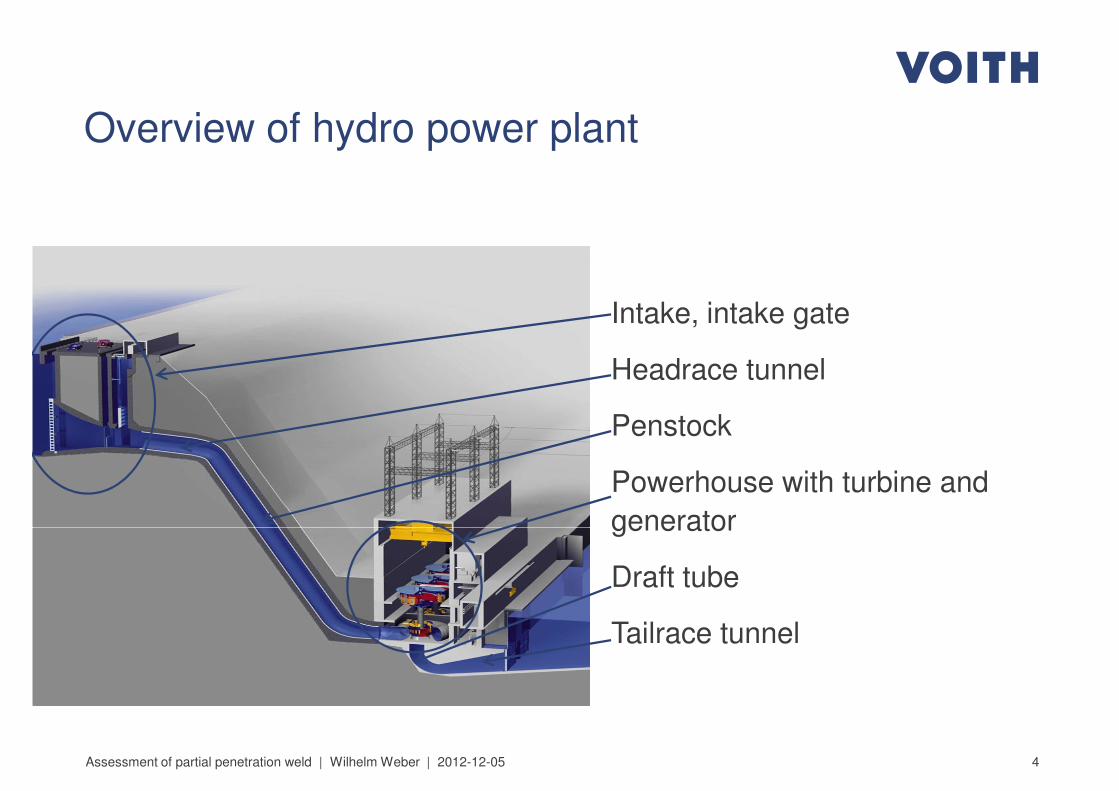
Overview of hydro power plant
Intake, intake gate
Headrace tunnel
Penstock
Powerhouse with turbine and
generator
4Assessment of partial penetration weld | Wilhelm Weber | 2012-12-05
generator
Draft tube
Tailrace tunnel
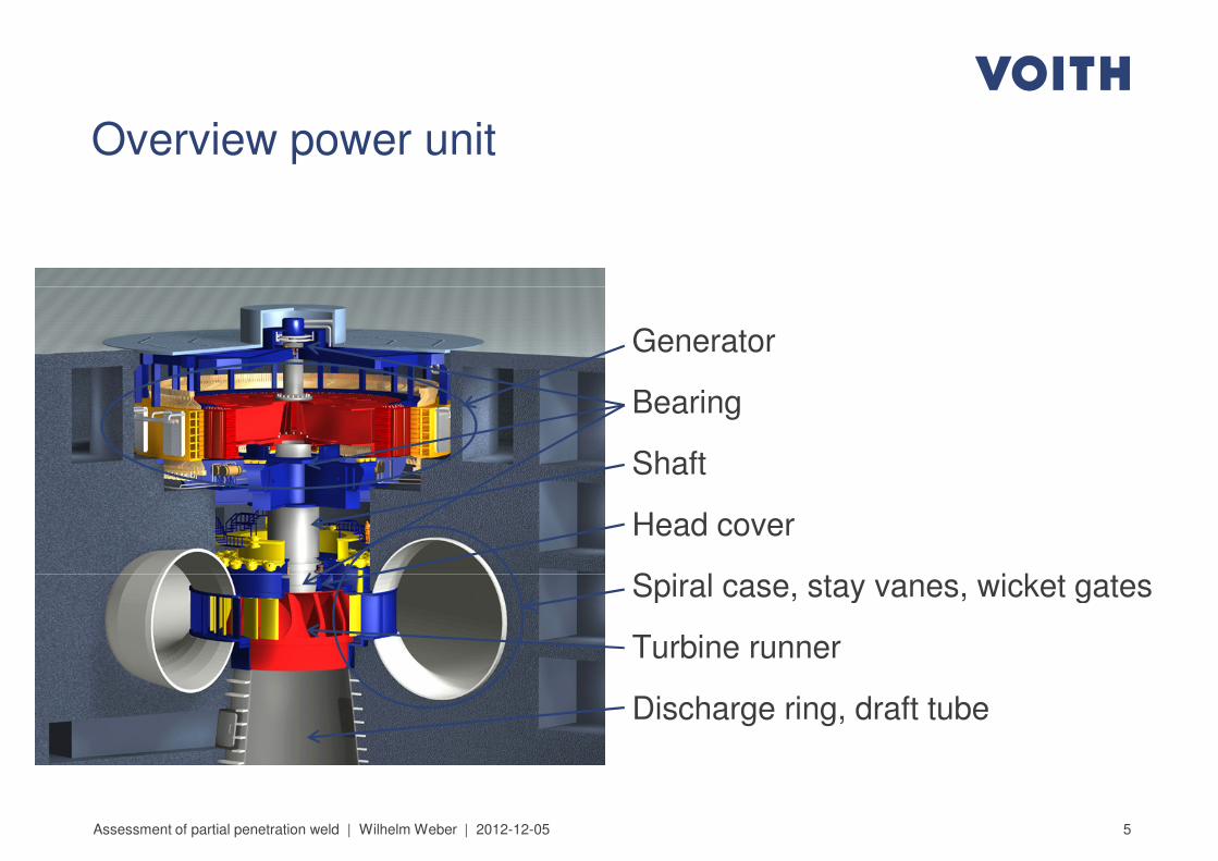
Overview power unit
Generator
Bearing
Shaft
Head cover
Spiral case, stay vanes, wicket gates
5Assessment of partial penetration weld | Wilhelm Weber | 2012-12-05
Spiral case, stay vanes, wicket gates
Turbine runner
Discharge ring, draft tube
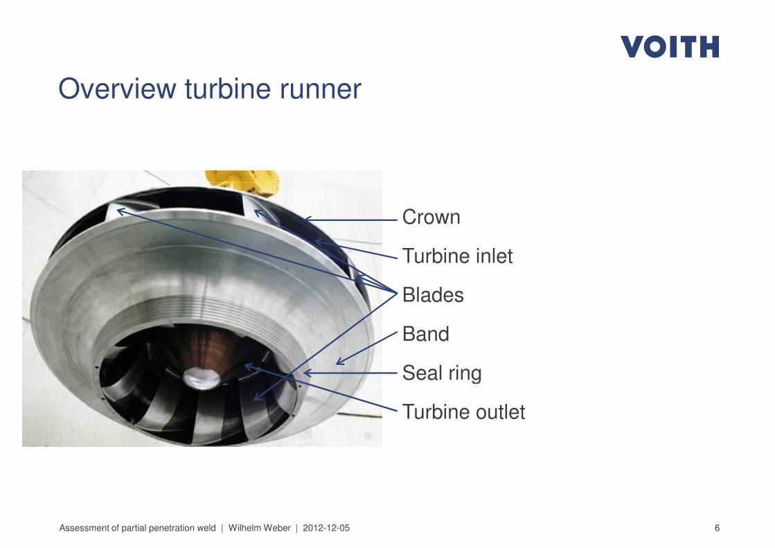
Overview turbine runner
Crown
Turbine inlet
Blades
Band
Seal ring
6Assessment of partial penetration weld | Wilhelm Weber | 2012-12-05
Seal ring
Turbine outlet
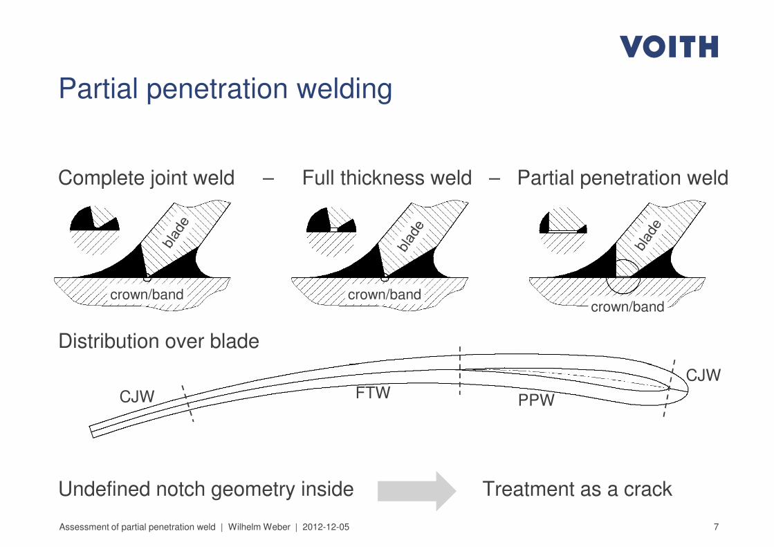
Partial penetration welding
Complete joint weld – Full thickness weld – Partial penetration weldComplete joint weld – Full thickness weld – Partial penetration weld
Distribution over blade
crown/band crown/bandcrown/band
7Assessment of partial penetration weld | Wilhelm Weber | 2012-12-05
Undefined notch geometry inside Treatment as a crack
CJW
CJWFTW PPW
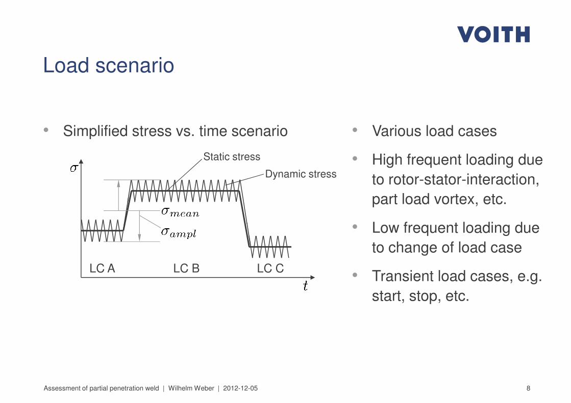
Load scenario
• Simplified stress vs. time scenario • Various load cases• Simplified stress vs. time scenario
Static stress
Dynamic stress
LC A LC B LC C
• Various load cases
• High frequent loading due
to rotor-stator-interaction,
part load vortex, etc.
• Low frequent loading due
to change of load case
• Transient load cases, e.g.
8Assessment of partial penetration weld | Wilhelm Weber | 2012-12-05
LC A LC B LC C• Transient load cases, e.g.
start, stop, etc.
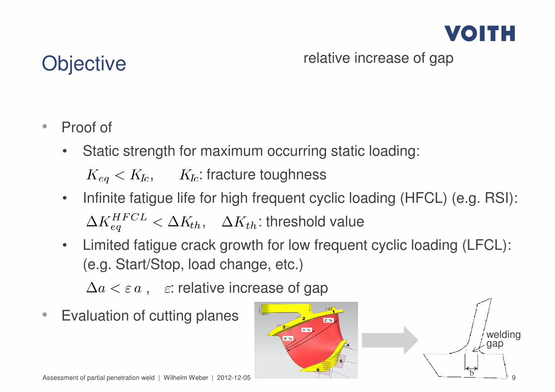
Objective
• Proof of
relative increase of gap
• Proof of
• Static strength for maximum occurring static loading:
, : fracture toughness
• Infinite fatigue life for high frequent cyclic loading (HFCL) (e.g. RSI):
, : threshold value
• Limited fatigue crack growth for low frequent cyclic loading (LFCL):
(e.g. Start/Stop, load change, etc.)
9
(e.g. Start/Stop, load change, etc.)
, : relative increase of gap
• Evaluation of cutting planes
Assessment of partial penetration weld | Wilhelm Weber | 2012-12-05
welding gap
b
Calculation and verification of stress intensity
factors
10Assessment of partial penetration weld | Wilhelm Weber | 2012-12-05
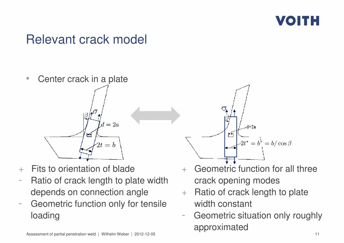
Relevant crack model
• Center crack in a plate• Center crack in a plate
11Assessment of partial penetration weld | Wilhelm Weber | 2012-12-05
+ Fits to orientation of blade
- Ratio of crack length to plate width
depends on connection angle
- Geometric function only for tensile
loading
+ Geometric function for all three
crack opening modes
+ Ratio of crack length to plate
width constant
- Geometric situation only roughly
approximated
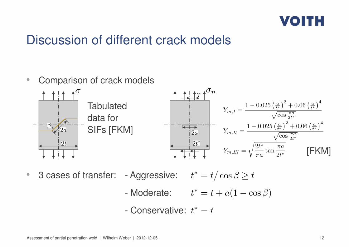
• Comparison of crack models
Discussion of different crack models
• Comparison of crack models
Tabulated
data for
SIFs [FKM]
[FKM]
12
• 3 cases of transfer: - Aggressive:
- Moderate:
- Conservative:
Assessment of partial penetration weld | Wilhelm Weber | 2012-12-05
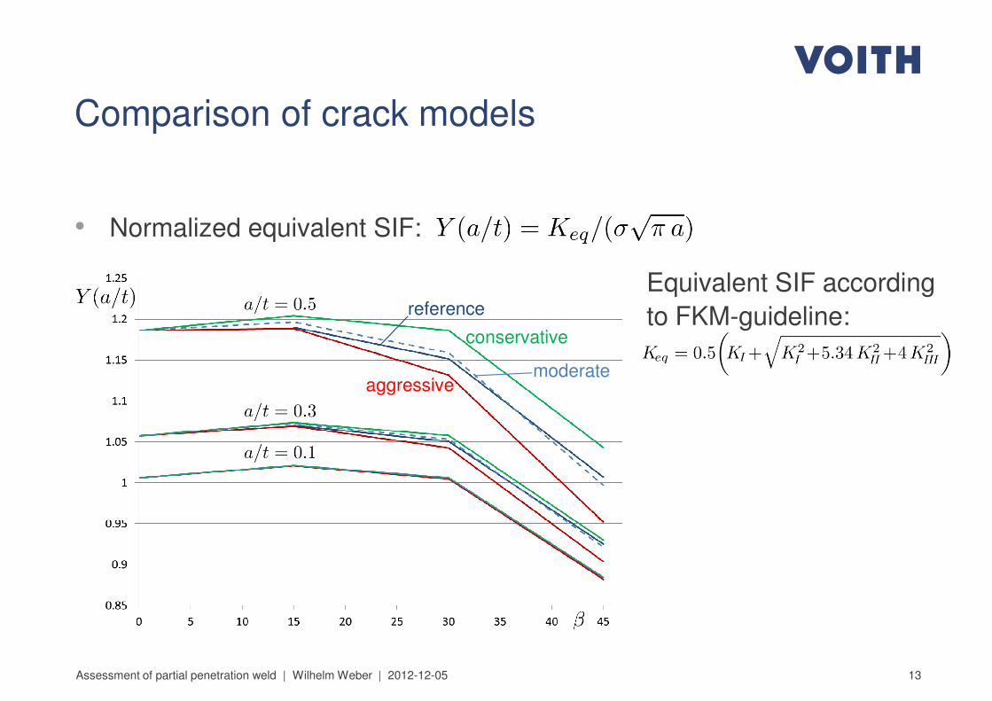
Comparison of crack models
• Normalized equivalent SIF:• Normalized equivalent SIF:
conservative
aggressivemoderate
reference
Equivalent SIF according
to FKM-guideline:
13Assessment of partial penetration weld | Wilhelm Weber | 2012-12-05
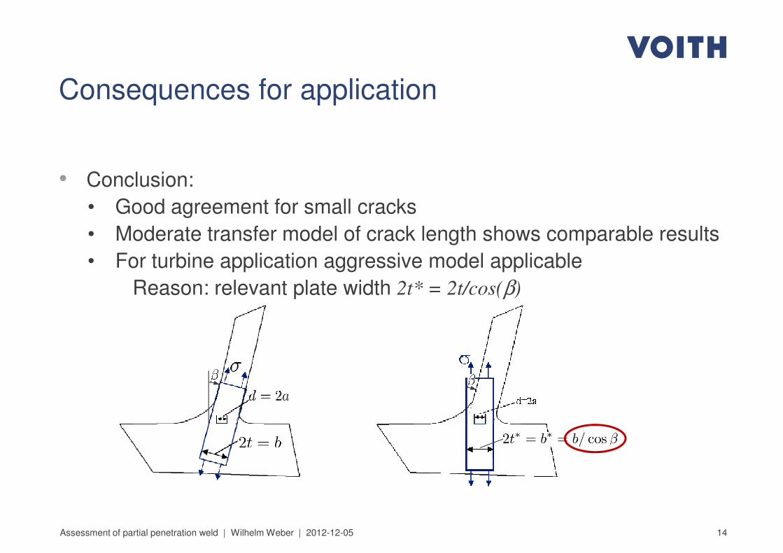
Consequences for application
• Conclusion:• Conclusion:
• Good agreement for small cracks
• Moderate transfer model of crack length shows comparable results
• For turbine application aggressive model applicable
Reason: relevant plate width 2t* = 2t/cos(β)
14Assessment of partial penetration weld | Wilhelm Weber | 2012-12-05
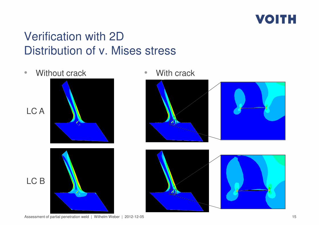
• With crack• Without crack
Verification with 2D
Distribution of v. Mises stress
• With crack• Without crack
LC A
15Assessment of partial penetration weld | Wilhelm Weber | 2012-12-05
LC B
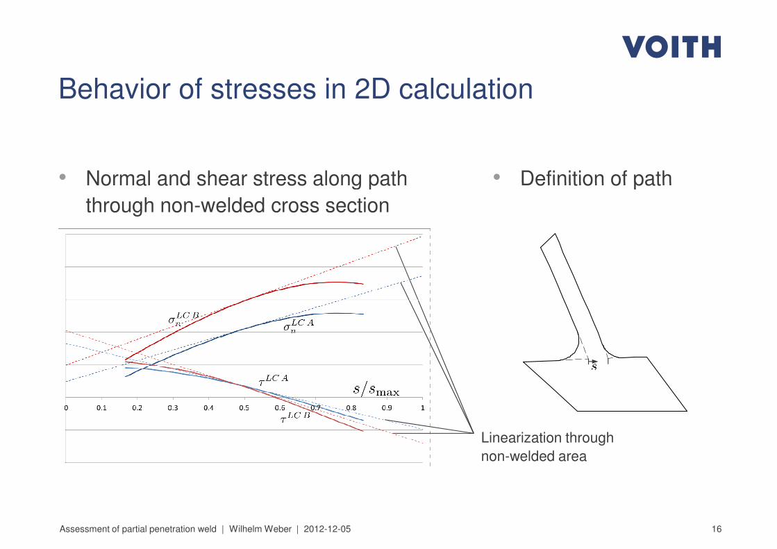
• Normal and shear stress along path
Behavior of stresses in 2D calculation
• Definition of path• Normal and shear stress along path
through non-welded cross section
• Definition of path
16Assessment of partial penetration weld | Wilhelm Weber | 2012-12-05
Linearization through
non-welded area
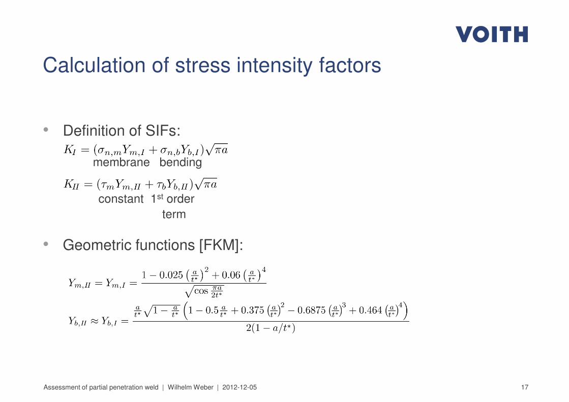
Calculation of stress intensity factors
• Definition of SIFs:• Definition of SIFs:
• Geometric functions [FKM]:
membrane bending
constant 1st order
term
17Assessment of partial penetration weld | Wilhelm Weber | 2012-12-05
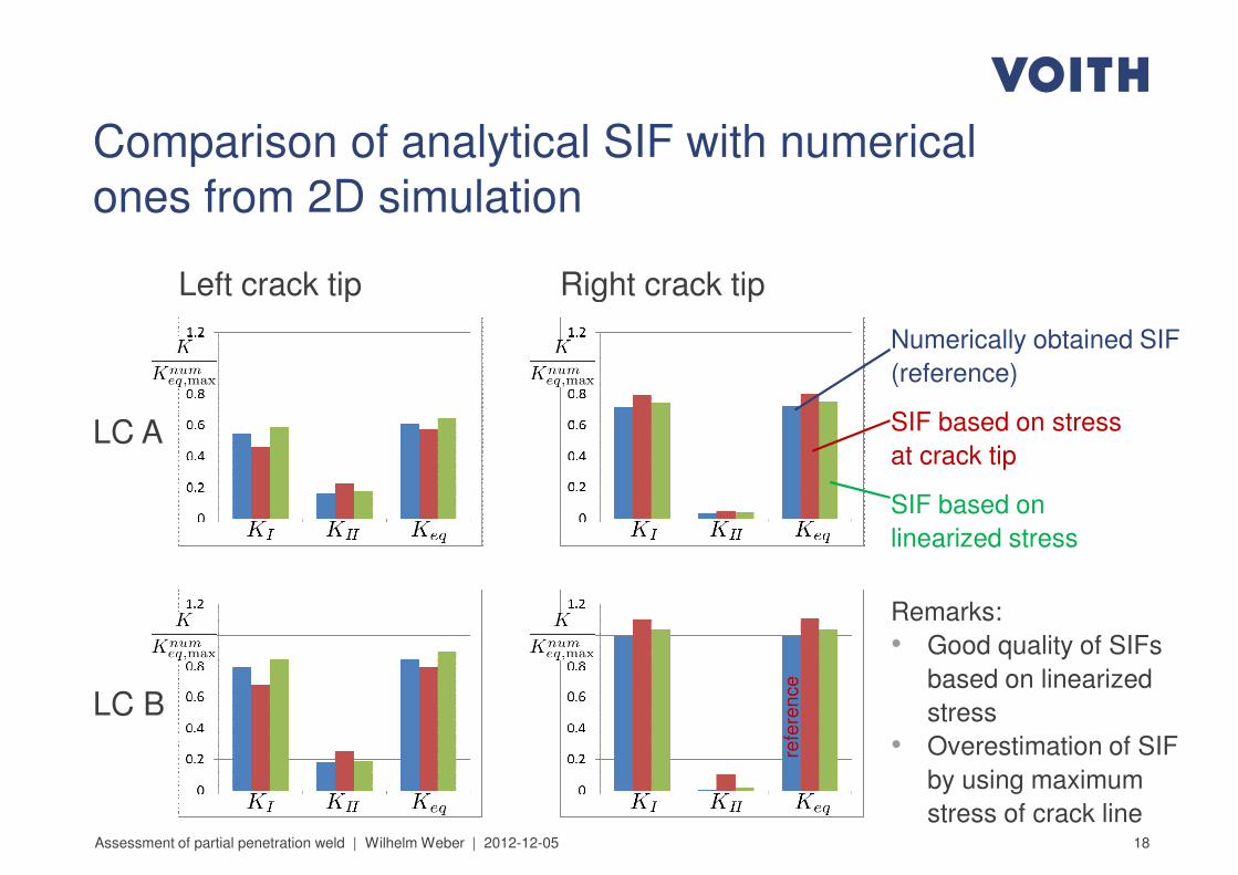
Comparison of analytical SIF with numerical
ones from 2D simulation
Left crack tip Right crack tipLeft crack tip Right crack tip
LC A
Numerically obtained SIF
(reference)
SIF based on stress
at crack tip
SIF based on
linearized stress
18Assessment of partial penetration weld | Wilhelm Weber | 2012-12-05
LC B
Remarks:
• Good quality of SIFs
based on linearized
stress
• Overestimation of SIF
by using maximum
stress of crack linere
fere
nce
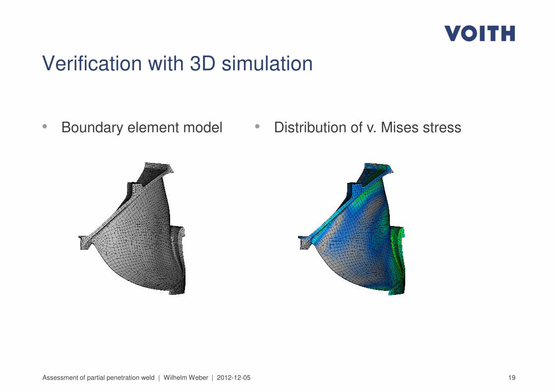
• Distribution of v. Mises stress
Verification with 3D simulation
• Boundary element model • Distribution of v. Mises stress• Boundary element model
19Assessment of partial penetration weld | Wilhelm Weber | 2012-12-05
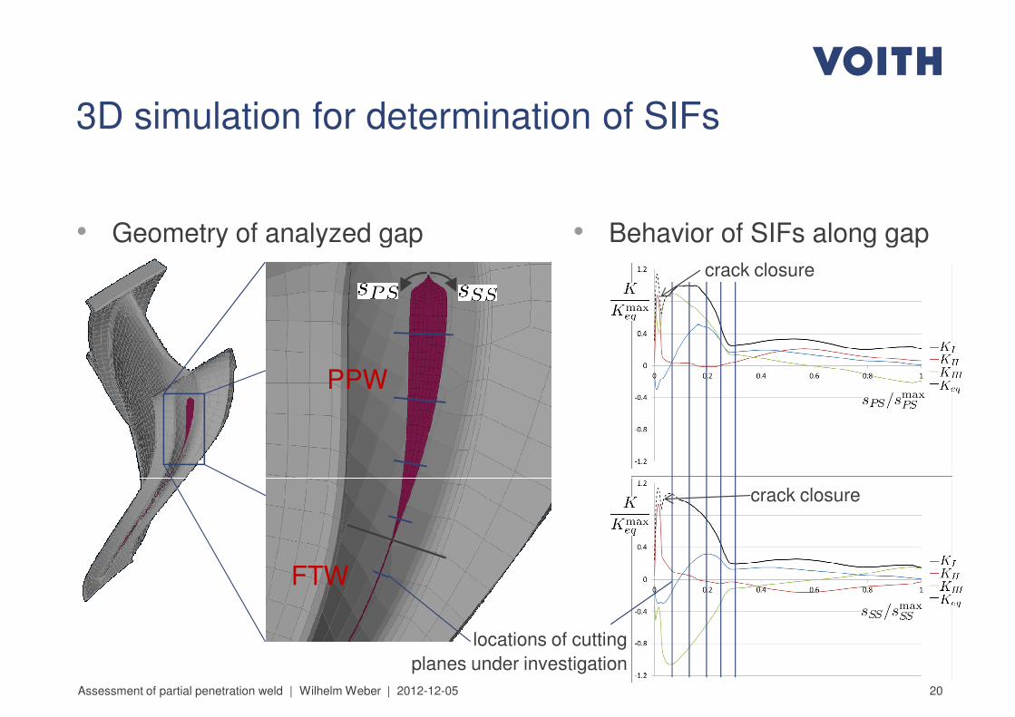
• Geometry of analyzed gap
3D simulation for determination of SIFs
• Behavior of SIFs along gap• Geometry of analyzed gap
PPW
• Behavior of SIFs along gap
crack closure
20Assessment of partial penetration weld | Wilhelm Weber | 2012-12-05
FTW
crack closure
locations of cutting
planes under investigation
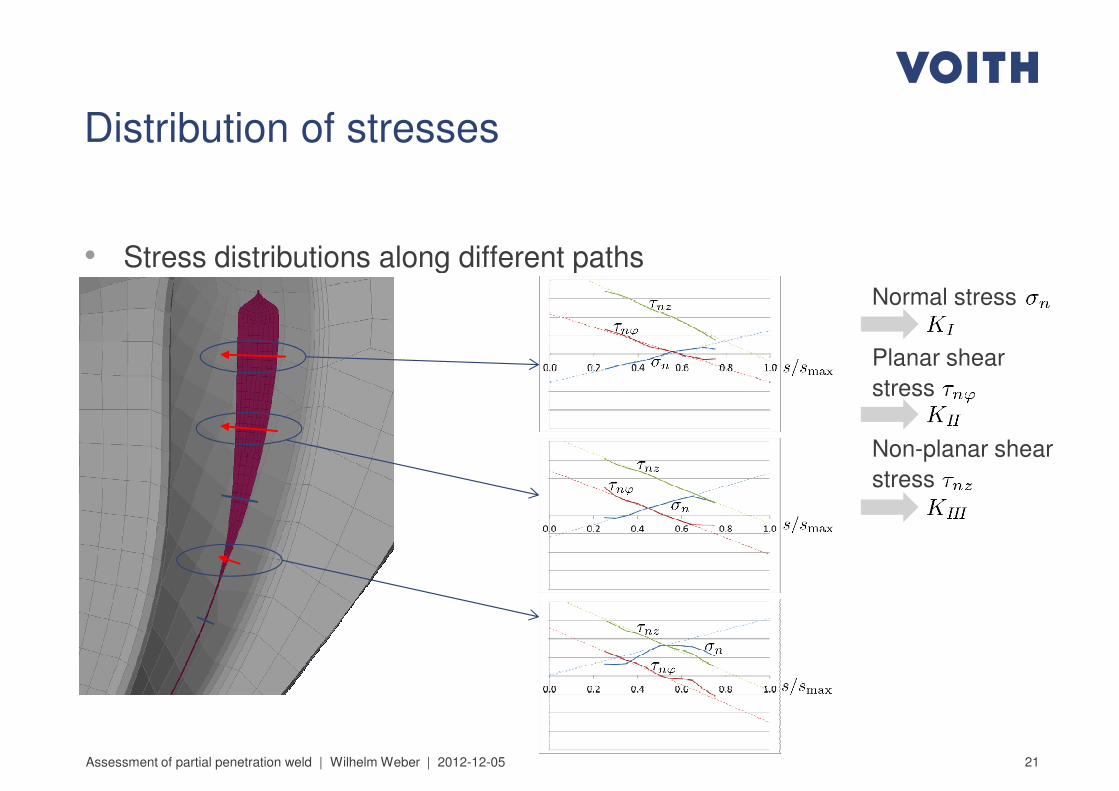
Distribution of stresses
• Stress distributions along different paths
Normal stress
Planar shear
stress
Non-planar shear
stress
• Stress distributions along different paths
21Assessment of partial penetration weld | Wilhelm Weber | 2012-12-05
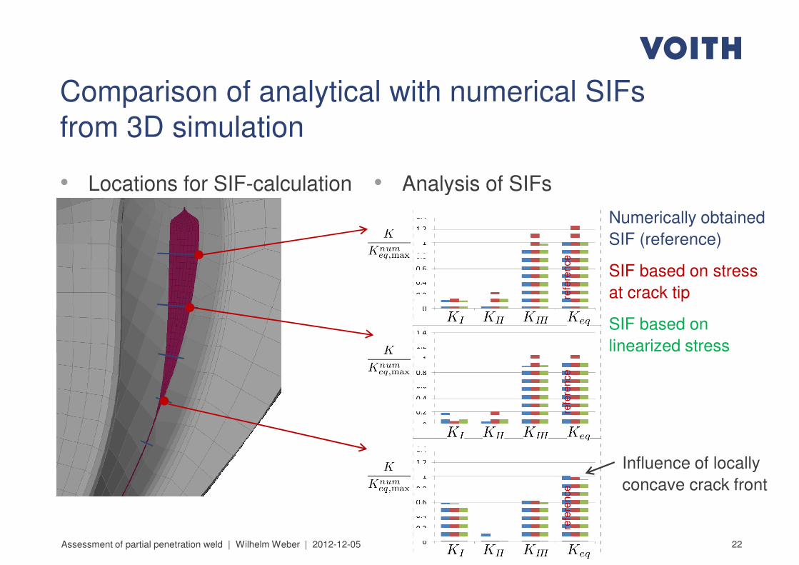
• Analysis of SIFs• Locations for SIF-calculation
Comparison of analytical with numerical SIFs
from 3D simulation
• Analysis of SIFs• Locations for SIF-calculation
Numerically obtained
SIF (reference)
SIF based on stress
at crack tip
SIF based on
linearized stress
refe
rence
refe
rence
22Assessment of partial penetration weld | Wilhelm Weber | 2012-12-05
refe
rence
refe
rence
Influence of locally
concave crack front

Fatigue crack growth
23Assessment of partial penetration weld | Wilhelm Weber | 2012-12-05
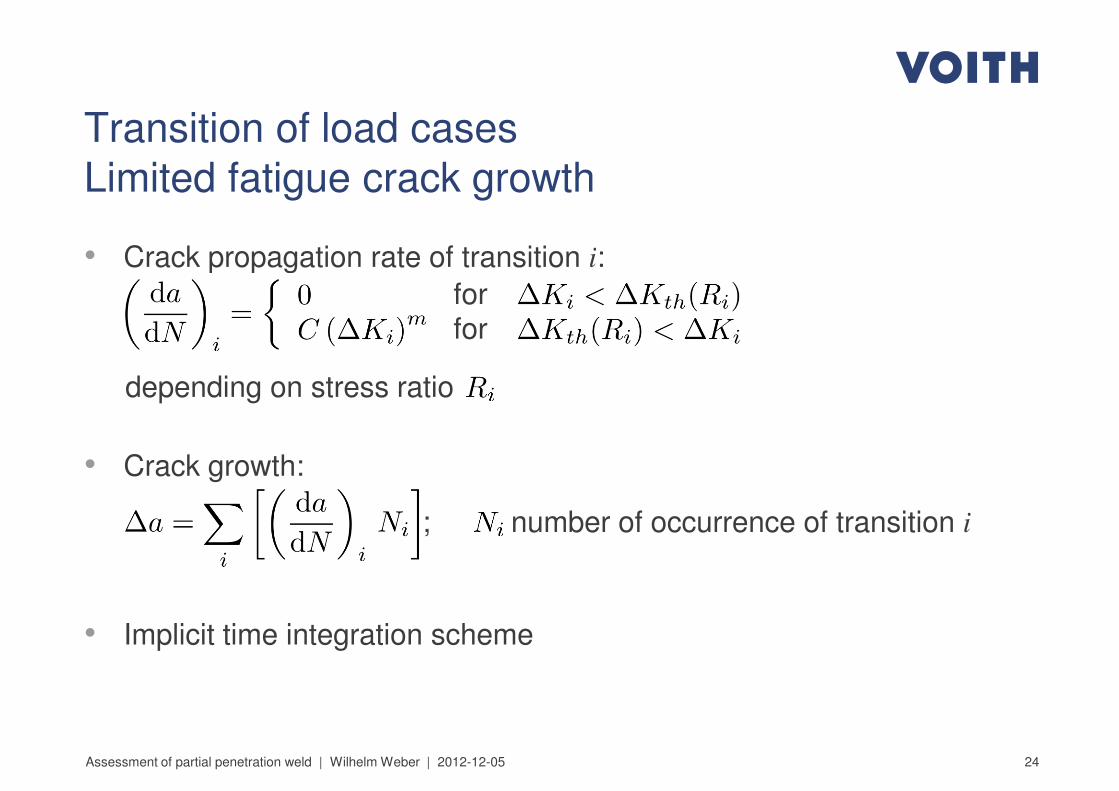
Transition of load cases
Limited fatigue crack growth
• Crack propagation rate of transition i:• Crack propagation rate of transition i:
depending on stress ratio
• Crack growth:
; number of occurrence of transition i
forfor
24
; number of occurrence of transition i
• Implicit time integration scheme
Assessment of partial penetration weld | Wilhelm Weber | 2012-12-05
Material resistance
25Assessment of partial penetration weld | Wilhelm Weber | 2012-12-05
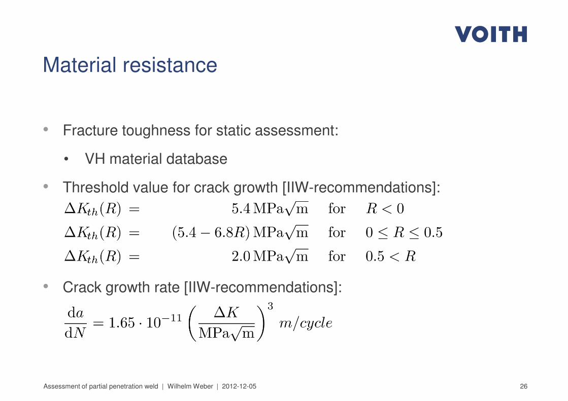
Material resistance
• Fracture toughness for static assessment:• Fracture toughness for static assessment:
• VH material database
• Threshold value for crack growth [IIW-recommendations]:
26
• Crack growth rate [IIW-recommendations]:
Assessment of partial penetration weld | Wilhelm Weber | 2012-12-05
Residual stresses
27Assessment of partial penetration weld | Wilhelm Weber | 2012-12-05
Residual stresses
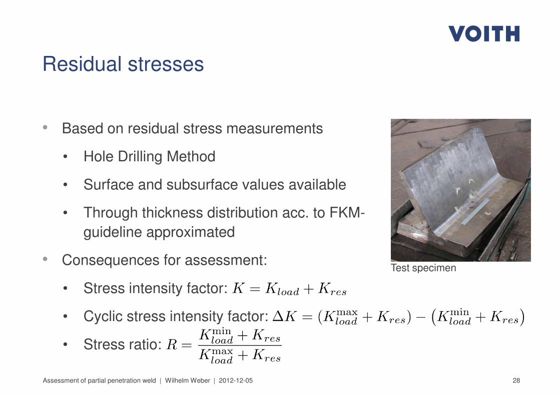
• Based on residual stress measurements• Based on residual stress measurements
• Hole Drilling Method
• Surface and subsurface values available
• Through thickness distribution acc. to FKM-
guideline approximated
• Consequences for assessment:Test specimen
28
• Consequences for assessment:
• Stress intensity factor:
• Cyclic stress intensity factor:
• Stress ratio:
Assessment of partial penetration weld | Wilhelm Weber | 2012-12-05
Test specimen

Assessment procedure
29Assessment of partial penetration weld | Wilhelm Weber | 2012-12-05
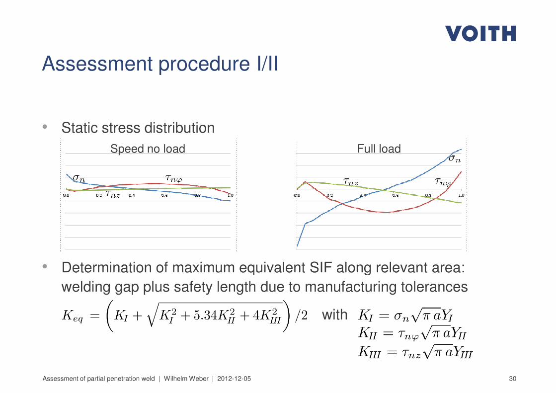
• Static stress distribution
Assessment procedure I/II
• Static stress distribution
• Determination of maximum equivalent SIF along relevant area:
Full loadSpeed no load
30
• Determination of maximum equivalent SIF along relevant area:
welding gap plus safety length due to manufacturing tolerances
with
Assessment of partial penetration weld | Wilhelm Weber | 2012-12-05
Assessment procedure II/II
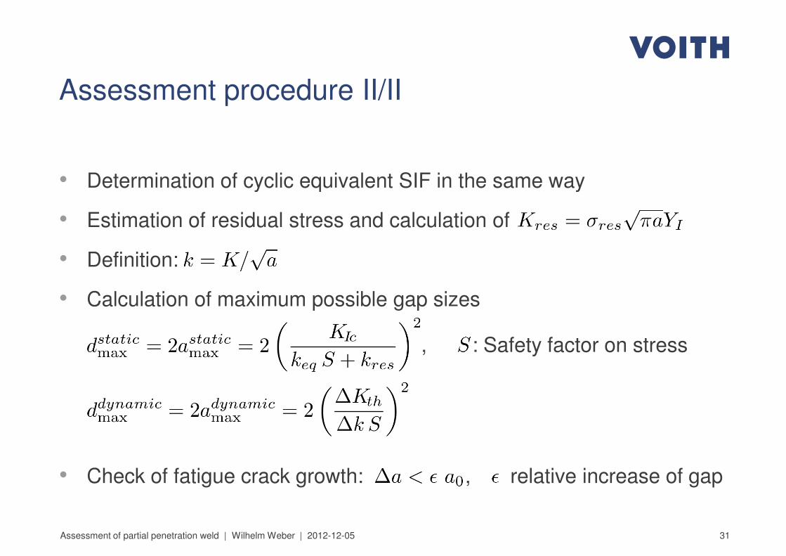
• Determination of cyclic equivalent SIF in the same way • Determination of cyclic equivalent SIF in the same way
• Estimation of residual stress and calculation of
• Definition:
• Calculation of maximum possible gap sizes
, : Safety factor on stress
31
• Check of fatigue crack growth: , relative increase of gap
Assessment of partial penetration weld | Wilhelm Weber | 2012-12-05

Summary
32Assessment of partial penetration weld | Wilhelm Weber | 2012-12-05
Summary
• Turbine runners are typically designed as welded structure.• Turbine runners are typically designed as welded structure.
• PPW is used to reduce manufacturing time and cost.
• Through-thickness crack in plate is chosen as crack model.
• Crack model is verified by comparison with 2D and 3D numerical
simulation.
• Fatigue crack growth can be assessed for cyclic loading due to load
33
• Fatigue crack growth can be assessed for cyclic loading due to load
change.
• Residual stresses are approximated for assessment procedure.
Assessment of partial penetration weld | Wilhelm Weber | 2012-12-05

Contact:Contact:
Dr.-Ing. Wilhelm Weber
Corporate Technology – R&D, Basic Development
Tel. 07321 37-9576
34Assessment of partial penetration weld | Wilhelm Weber | 2012-12-05

35Assessment of partial penetration weld | Wilhelm Weber | 2012-12-05