assessment and certification of seooc components
TRANSCRIPT

Assessment and Certification of SEooC Components

Outline SP Technical Research Institute of Sweden
Safety contracts for Safety Elements out-of-Context (SEooC) Example on assessment and certification process for SEooC by using safety contracts
SafetyADD tool developed by SP (SafeCer project)
Fault injection at different abstraction levels MODIFI tool (MOGENTES/BeSafe/VeTeSS projects)
FI-based B2B testing of SEooC components using MODIFI and GOOFI (VeTeSS)
Safe transitions from automated to manual driving (SHADES project)

SP in figures
SP Group owners 100% RISE
Subsidiaries 10
Employees 1400
Turnover EUR 148 million
Customers More than 10,000

Research Testing Calibration
Certification Courses and seminars SME

Food and Biotechnology
Machine Testing and Inspection
Measurement Technology
Process Development Wood Technology
Electronics Energy Technology Glass Research Agricultural and Environmental Engineering
Calibration and Verification
Chemistry, Materials and Surfaces
Concrete and Stone Bioeconomics Fire Research Structural and
Solid Mechanics Certification Active Safety
Water
Activities

Participation in EU projects on Dependable systems DECOS: SP evaluated e.g. effects of communication faults (using TTTech disturbance node)
MOGENTES: SP developed e.g. a B2B fault injection testing tool chain
SARTRE: Platoons, cooperative systems, SP responsible e.g. for communication nodes
ActiveTest: Testing of active safety systems, successor to eVALUE project
SafeCer: Safety certification, reusable SW components, safety arguing for composable systems
VeTeSS: Verification & Test Support for Safety Standards, SEooC (Safety Elements out of Context). SP has e.g. enhanced the work with FI-based B2B testing for model-based design
Karyon: Predictable and safe coordination of smart vehicles that autonomously cooperate in an uncertain environment. SP developed e.g. a quadcopter demonstrator (hw, sw, wireless FI)
PROWESS: SP has e.g. combined Fault injection (evaluate/exercise fault handling) and Property-based testing (finding bugs) in the same experiments

Safety Contracts - Cruise Controller Example
– Traditionally, safety certification is carried out on a complete system (in-context)
– Can a Software supplier develop independent improvements (Safety Element out-of-Context)?
– How is responsibility for safety distributed then?

Independent innovation by SW Supplier

Safety Contract – Tailoring of ISO 26262 Safety Life Cycle
6-9 Software unit
testing
4-7 System design
6-7 Software architectural
design
6-8 Software unit design and implementation
6-10 Software integration and
testing
6-11 Verification of
safety requirements
4-8 Item integration and
testing
6-6 Specification of software safety requirements
SWC development(SEooC)
6-5
Initi
atio
n of
pro
duct
dev
elop
men
t at
the
softw
are
leve
l
Safety Contract
2-4 Requirements for compliance 2-5 Overall safety management
2-6 Safety management during the concept phase and the product development
8 Supporting processes
Safety Contract
ISO 26262 Part 1: Vocabulary Part 2: Management of functional safety Part 3: Concept phase Part 4: Product development at the system level Part 5: Product development at the hardware level Part 6: Product development at the software level Part 7: Production and operation Part 8: Supporting processes Part 9: ASIL-oriented and safety-oriented analyses Part 10: Guideline on ISO 26262

Safety Element Contract
Data Sheet
references
Safety Element Contract Guarantee • GreeSetSpeed never over 5% of driver’s
chosen speed more than 10s, ASIL A • GreeSetSpeed never over 25% of driver’s
chosen speed more than 1s, ASIL A
Assume • SetSpeed as specified by CC HMI with a
maximum delay of 0,2s, ASIL A

Accredited Independent Assessor
Component Supplier
Defines
Safety Assessor
Assesses
Accredited Safety Assessment Report
Accreditation Body
Accreditation Body – An authority – Not a safety assessor
Accreditation implies – Assessor is
competent – Assessor is
independent – Assessor in
continuously evaluated
Applicable parts of Life Cycle

Summarizing in Certificate
Accredited Safety Assessment Report
Safety Assessment Report – Contains many details – Irrelevant for OEM – Intellectual Properties not to
share with OEM
Certificate – Sufficient information OEM
needs for Safety Case – Not containing sensitive IP – Suited to publish on supplier’s
web site
Issues
Safety Assessment Certificate
Certification Body

Out-of-Context Development and Assessment
Component Supplier
Safety Element Contract
Applicable parts of Life Cycle
Safety Assessor
Assesses
Accredited Safety Assessment Report
Certification Body
Accreditation Body
Issues
Accredited Safety Assessment Certificate
Out-of-Context development and assessment Note that no OEM is present during this process
13

SEooC Deployed by Several OEMs

Safety contract based design using SafetyADD

Design support

Assessment support

BeSafe - Benchmarking of Functional Safety
Comparison
A1
A2
Which one is safer?
A C B + + = ?
How safe will it be?
Properties
A2 ” ”, please.
OK
Requirements
Profiling
Any weak spots?
A B C
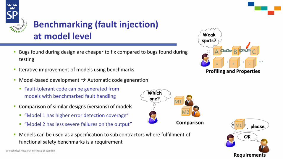
Benchmarking (fault injection) at model level
Bugs found during design are cheaper to fix compared to bugs found during testing
Iterative improvement of models using benchmarks
Model-based development Automatic code generation
Fault-tolerant code can be generated from models with benchmarked fault handling
Comparison of similar designs (versions) of models
“Model 1 has higher error detection coverage”
“Model 2 has less severe failures on the output”
Models can be used as a specification to sub contractors where fulfillment of functional safety benchmarks is a requirement
Profiling and Properties
Weak spots?
A B C A C B
+ + = ?
Comparison
M1
M2
Which one?
M1 ” ”, please.
OK
Requirements

MODIFI (MODel-Implemented Fault Injection) tool MODIFI is a fault injection tool for Simulink models Useful for early dependability evaluation of software developed as models
Provides a large number of fault models, e.g., bit-flip faults and sensor faults
Includes support for analyzing and visualizing fault injection results

Visualization techniques
Progress visualization for real-time status of fault injection campaigns
Sensitivity profiling for robustness visualization (for a FI campaign)
Error propagation analysis for understanding of the model and for evaluation of error handling mechanisms (for a single FI experiment)

Fault models (Failure modes) – ISO 26262 ISO 26262 Part 5 - Product development at the hardware level Table D.1 - Analyzed faults or failures modes in the derivation of diagnostic coverage
ISO 26262 fault models include (from Table D.1): Sensor (including signal switches) faults Stuck-in-range (Low DC = 60%) Stuck-out-of-range (Low DC = 60%) Offsets (Medium DC = 90%) Oscillations (High DC = 99%)
“direct current (d.c.) fault model” Stuck-at faults, stuck-open, open or high impedance outputs, short circuits
“soft error model” Includes bit-flip faults

Supported fault models in MODIFI
E.g. bit-flip fault model to emulate the effects of transient faults
Different fault models for sensors
Lower limitUpper limit
Out of range Stuck in range
Offset Oscillation
Fault injected
Stuck at zero
Sen
sor v
alue
TimeFault injected
Gain
Time

Fault Injection at Different Abstraction Levels
Model-implemented, software-implemented and hardware-implemented fault injection
Implementation
models Object code
C code
Back-to-back comparison
Code generation, Compilation & Linking

Fault injection, Simulink, Functional Safety Standard ISO 26262

Example workflow for model-based development:
“The test environment for software unit testing shall correspond as closely as possible to the target environment. …” ISO2626-6, 9.4.6
Testing on models
Textual
requriements
Abstract
models
Implementation
models Object code C code …
Code generation
Compilation & linking
Modeling

Testing on models (cont’d)
Example workflow for model-based development:
For model-based development: ISO2626-6, 9.4.6 NOTE 4
Perform software unit testing at the model level Use back-to-back comparison to ensure that the behaviour of the models with regard to the test objectives is
equivalent to the automatically-generated code
Textual
requriements
Abstract
models
Implementation
models Object code C code …
Back-to-back comparison
Code generation
Compilation & linking
Modeling
Testing on models Target system testing

Example workflow (to be presented at SafeComp15) Objective: Demonstrate that software developed using Simulink models achieves robustness. (ISO 2626-6, 9.4.3, 10.4.3)
Fault injection is needed to test error detection and handling.
1. Select workload and faultload
2. Perform fault injection on the Simulink model using MODIFI
3. Generate code from model, compile and download to target HW
4. Use physical fault injection (GOOFI) and perform back-to-back testing with the same workload, but a subset of the faultload
5. Check that the obtained results are equivalent with respect to the test objectives

Safe transitions from automated to manual driving Separate slides…

Thanks for your attention
Questions?


The SHADES project
SHADES - System safety through combination of HMI and Dependable Systems

Driver assistance systems
• Information/Warning Systems – Forward Collision Warning – Lane Departure Warning – Blind Spot Monitoring
• Active assistance/Semi automation – Collision Avoidance by Braking – Lane Keep Assist – Adaptive Cruise Control
• Full/High automation – Lateral and longitudinal automation – Platooning
longitudinal
lateral

Focus in this study
Driver assistance
system
Driver
Vehicle
malfunctions that cause hazards

• Adaptive Cruise Control (ACC) • Driving simulator study • Four failure modes
– Unwanted acceleration – Complete brake failure – Partial brake failure – Speed limit violation
• There was no warning indicating a failure • All with the same initial settings
– ACC activated – 105 kph (65 mph) – Following leader with a 2 second time-gap – No vehicle in left lane (free to overtake)
Experimental setup
Ego
Lead
2 s

Chalmers driving simulator

Driving simulator experiment – Fault injection support
Upper level controller
Relative Velocity
Relative Distance
Own Velocity
Set Time-Headway
Set Maximum-Speed
Desired Acceleration
Lower level controller
Desired Acceleration
Engine torque
Brake pedal position

Driving simulator experiment – Adaptive cruise control
Upper level controller
Relative Velocity
Relative Distance
Own Velocity
Set Time-Headway
Set Maximum-Speed
Desired Acceleration
Lower level controller
Desired Acceleration
Engine torque
Brake pedal position
Fault injection
block
Fault injection
block
Speed failure
Unwanted acceleration
Complete brake failure
Partial brake failure

• 48 participants – 33 men and 15 women – between 25 and 59 years of age – annual driving distance more than 5000 km – no experienced ACC users
Participants

Scenario A: Unwanted acceleration
Braking or steering required to avoid collision
Car in front drives at 105 kph (65 mph), ACC in ego car accelerates unintentionally towards vehicle ahead (fails to keep the set distance and speed)
Fails to follow leader with a 2 second time gap

Scenario B&C: Complete and partial brake failure
Braking or steering required to avoid collision
B: Car in front brakes, ACC in ego car does not brake
C: Car in front brakes, ACC in ego car brakes less than necessary to avoid a collision

Scenario D: Speed limit violation
Braking required to avoid speeding 110
90 110 100
Car in front accelerates above speed limit, ACC in ego car also accelerates keeping set distance (2s) but fails to keep set speed limit (110 kph)
Following leader with a 2 second time-gap

Order of scenarios Subjects 1 2 3 n = 4 Practice A B n = 4 Practice B A n = 4 Practice A C n = 4 Practice C A n = 4 Practice A D n = 4 Practice D A n = 4 Practice B C n = 4 Practice C B n = 4 Practice B D n = 4 Practice D B n = 4 Practice C D n = 4 Practice D C
Design
* A=B=C=D=Experimental scenario including experimental situation and preceding baseline ** N = 48 *** n = 24 for each experimental scenario

RESULTS

The drivers available strategies when system fails

Scenario A: Ego car accelerates unintentionally
• No collisions
• Majority used steering
• One third slowed down – Six braked
– One turned off the ACC using the button
• Three drivers got the vehicle unstable which automatically aborted the experiment

Scenario B&C: Brake failures
• Both brake failures caused collisions
• Partial brake failure caused more collisions than complete failure – But with lower impact speed (36
kph vs. 82 kph)!
• Changing lane most common for drivers with successful outcome
Complete brake failure
Partial brake failure

Scenario D: Ego car accelerates keeping the set distance but fails to keep the set speed limit • Eight drivers did nothing within 30 seconds of speeds
above 110 kph • Braking more common than pressing the ACC on/off
button

Conclusions
• More drivers changed lane than braked to acceleration and brake failures – But note that drivers were always free to change lane
• Collisions only occurred in scenarios with brake failures • More collisions for partial brake failure than for complete
brake failure – However, impact speed was less for partial brake failure
• Comparing brake failures: – Higher controllability for complete brake failure (fewer collisions) – Lower severity for partial brake failure (lower impact speed)
Risk = Exposure x Controllability x Severity

Human Interactive Autonomous Driving – Challenges • Safe transitions from automated to manual driving?
– Disable automated control may not be safe! – How should the driver be included in the loop when system fails?
• Driver cannot take over in all situations Back-up needed? – What can the system do before including the driver?
TTC
Acceleration
THW
Driver controllability set
Safe transition?

Human Interactive Autonomous Driving – Research Perspectives • Cooperation needed between different research areas
– Main goal of the SHADES project – E.g. Human behavior science, Control theory and Dependable
systems
• Drivers can behave differently depending on level of
automation – We have carried out a driving simulator study (with brake failures)
comparing longitudinal control (ACC) with longitudinal and lateral control (Traffic Jam Assist, TJA)
– Preliminary simulator results show that going from ACC to TJA leads to worse performance when longitudinal automation fails