assembly manual - seascape...
TRANSCRIPT

Assembly Manual
DRAFT31 / 3 / 2017

2
0) The Equipment
Dear ownerYou are holding the first draft of the Assembly Manual for your brand new Seascape24. It was de-signed to help you with the first assembly of your boat. We also included some sections which should help you with some tips and tricks regarding the launch, mast hoist and other operations you will encounter while using her. As mentioned this is the first draft which we plan to update on regular in-tervals so check back to Knowledge base section of www.thinkseascape.com for the latest versions. For technical details always refer to the Owners manual you received with your boat.
Fair winds and lots of funYours Seascape

3
1) The Mast and Rigging
Content of the cardboard box with small equipment.
Parts needed to assemble your mast with standing and running rigging.
Make sure you untwist the halyards before installing them. Use the pilot line to pull the halyard trough the mast tube. Make sure to use electric tape when you attach the halyard to the pilot line.
4
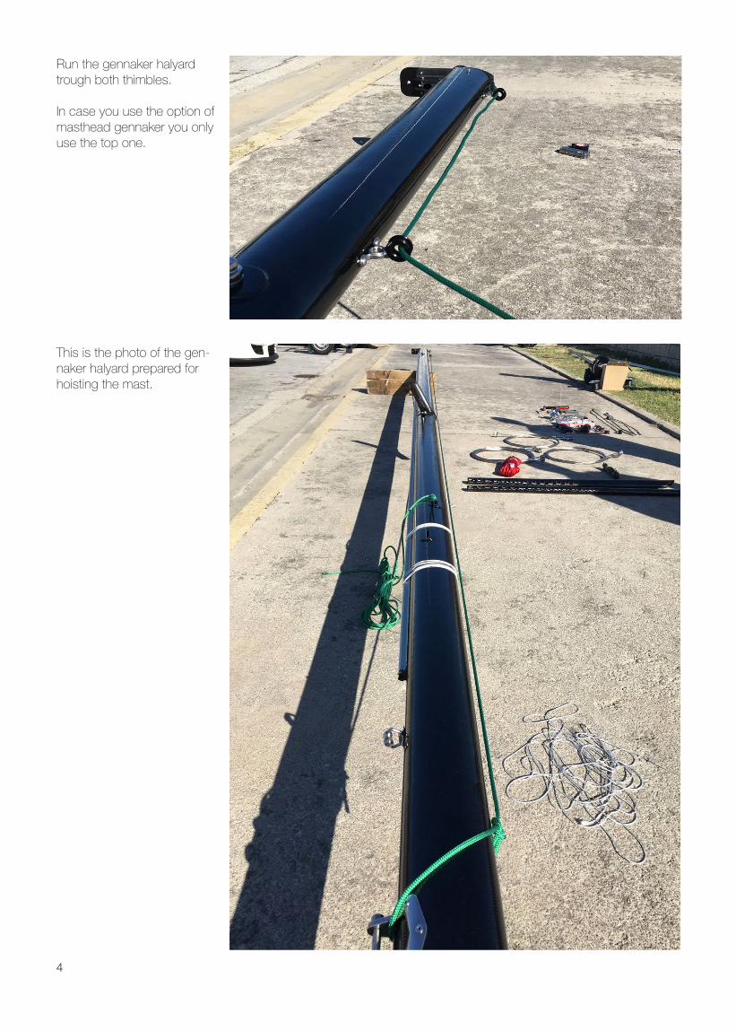
Run the gennaker halyard trough both thimbles.
In case you use the option of masthead gennaker you only use the top one.
This is the photo of the gen-naker halyard prepared for hoisting the mast.

5
Seascape 24 features 2:1 main halyard to reduce com-pression on the mast tube.
Pin holes for spreaders are make them asymmetric so make sure you match the markings on the spreaders with those on spreader butts.
Use electric or Vulcanizing tape to protect the Spreader pins.

6
Unscrew turnbuckles from the shrouds and forestay. Make sure not to loose lock-ing nuts.
Attach toggles with turnbuck-les on the chain-plates and secure the pins with electric/vulcanizing tape.
Attach forestay toggle to the jib furler and attach the furler to the bow. Again make sure to secure the split pins with some tape.

7
Slide shrouds into the spreader slots. Make sure to tighten the screw which is securing the shrouds in the slot.
Attach the shrouds to the mast hounds. When new the hounds are quite close to the mast so be careful not to scratch the paint when attaching the shrouds. They will bend outwards after first use. Use electric tape to protect the safety pins.
Attach the top jib furler on the forestay hound and secure the split pins with electric tape.Attach Slide thicker (4mm) part of jib halyard trough the block on the furling mechanism and pull it to the point where the thinner part of the halyard (3mm) reaches the block (see next photo).

8
Pull the jib halyard to the point where the thinner part of the halyard reaches the block on the furler. Make sure that you always end up with the loop of the thicker end of the halyard sticking out of the furler.
Tie the think and thin end of the jib halyard together so you don’t loose it when stepping the mast.

9
2) Setting the mast using the A-frameA frame comes with following parts. It is powder coated so make sure you don’t damage the paint to prevent corro-sion.
Slide the top part of the tube into the bottom part of the tube and secure it using the pin. Make sure you tighten the nuts all the way.
The aft support lines are already attached to the top of the A-frame. Use the gennaker sheets for forward support. Attach them to the side rings on the top of the A-frame.Use composite shackle to attach one of the blocksUse Tack-line for the mast hoist line. Run it trough the thimble and tie the loose end together.

10
Once the A-frame is ready put the mast on the boat as shown. After the first assem-bly of the mast when all the halyards are already in place you can assemble the mast on the boat to simplify ma-nipulation.
Use a fender on the coach roof for supporting the mast as you will reposition it in the hoist position. (Left)
Attach the aft A-frame sup-port lines on the pad-eyes as shown on the photo (right)
Leverage the A-frame against the stanchions and attach the aft support lines on the deck.

11
Reposition the mast to the center of the boat and for-ward as shown on the photo.
Prepare the forward support lines - make sure they are lead trough the triangle be-tween the mast, the spread-er and the V1 (top shroud).
Leverage the A-frame against the stanchion and push/pull it forward to lift it in vertical position.

12
Move the legs of the A-frame backwards...
So it is positioned roughly 20cm forward of the Shroud chain-plates.
Attach front A-frame support lines on the forward mooring cleats.
Repeat the process on both sides.
Double-check weather the support lines are lead trough the triangle of mast/spread-er/top shroud.

13
Attach the hoist line on the mast with a loop. Make sure to leave a long tail on the bowline so you can pull the loop downwards after the mast is hoisted. The loop can jam under the lower shroud hounds.
Lead the other end of the hoist rope trough the mast foot block and the clutch to the winch.
The mast is a little bit top heavy so keep slight pres-sure on the foot while hoist-ing. Use the Winch to lift the mast.
Once the mast is raised swing the mast foot over the mast support and gently lower it in place. Keep a slight tension on the hoist rope until you secure the mast with the shrouds and forestay.

14
Attach the shrouds and forestay. Upper shrouds are lead outside of the guardrail while the lower shrouds are lead inside.
When you are attaching the turnbuckles make sure that the threads are evenly lead into the turnbuckles.
Put the rig under tension using number 8 and 14 fork key. Use the screwdriver to help you fix the forestay furling drum as shown on the photo. Set the forestay rake as shown on the photo on the right.
Recommended rig tensions for the Seascape 24 as measured with the Loos type A tensiometer (supplied with the boat).
Light Medium HeavyTop shrouds (V1) 30 Lower shrouds D1) 20ForestayForestay rake
15
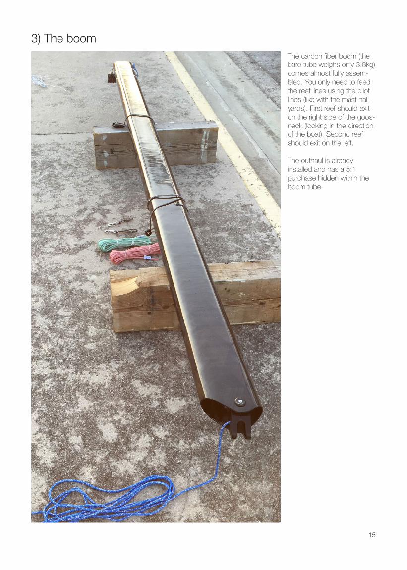
3) The boomThe carbon fiber boom (the bare tube weighs only 3.8kg) comes almost fully assem-bled. You only need to feed the reef lines using the pilot lines (like with the mast hal-yards). First reef should exit on the right side of the goos-neck (looking in the direction of the boat). Second reef should exit on the left.
The outhaul is already installed and has a 5:1 purchase hidden within the boom tube.

16
Attach the boom to goos-neck as shown on the photo. Attach the reef hooks around the goos-neck pin.
Make sure to put the plastic washer between the bot-tom of the boom part of the goos-neck and the mast goos-neck.
Attach Main sheet A-frame to Rope-eye loops using the composite shackles.
Attach triple block on the top of the A-frame.
Attach Main sheet A-frame to Rope-eye loops using the composite shackles.
Attach triple block on the top of the A-frame.
Run the Main sheet trough the purchase system...

17
And the Vang. Assemble it as shown on the photo.
... and trough the Main sheet ratchet. The arrow on the block should be pointing towards the trimmer.To engage the ratchet turn the red lever on both sides of the block.To engage automatic func-tion slide the black slider inside the red lever on both sides of the block.
Attach the tail ends of the vang cascade on the t-bone attached to the mast foot.

18
4) The Pit
Looking at the picture from right to left:
- Tack-line,- Pole out - Jib furling- Gennaker- 1st reef- Cunningham- Vang- Outhaul- 2nd Reef- Main halyard
In case of “Classic jib halyard option” there is additional mast food block and a clutch for jib halyard.
The mast foot with rope arrangements.
19
5) The Sails
a) The Jib
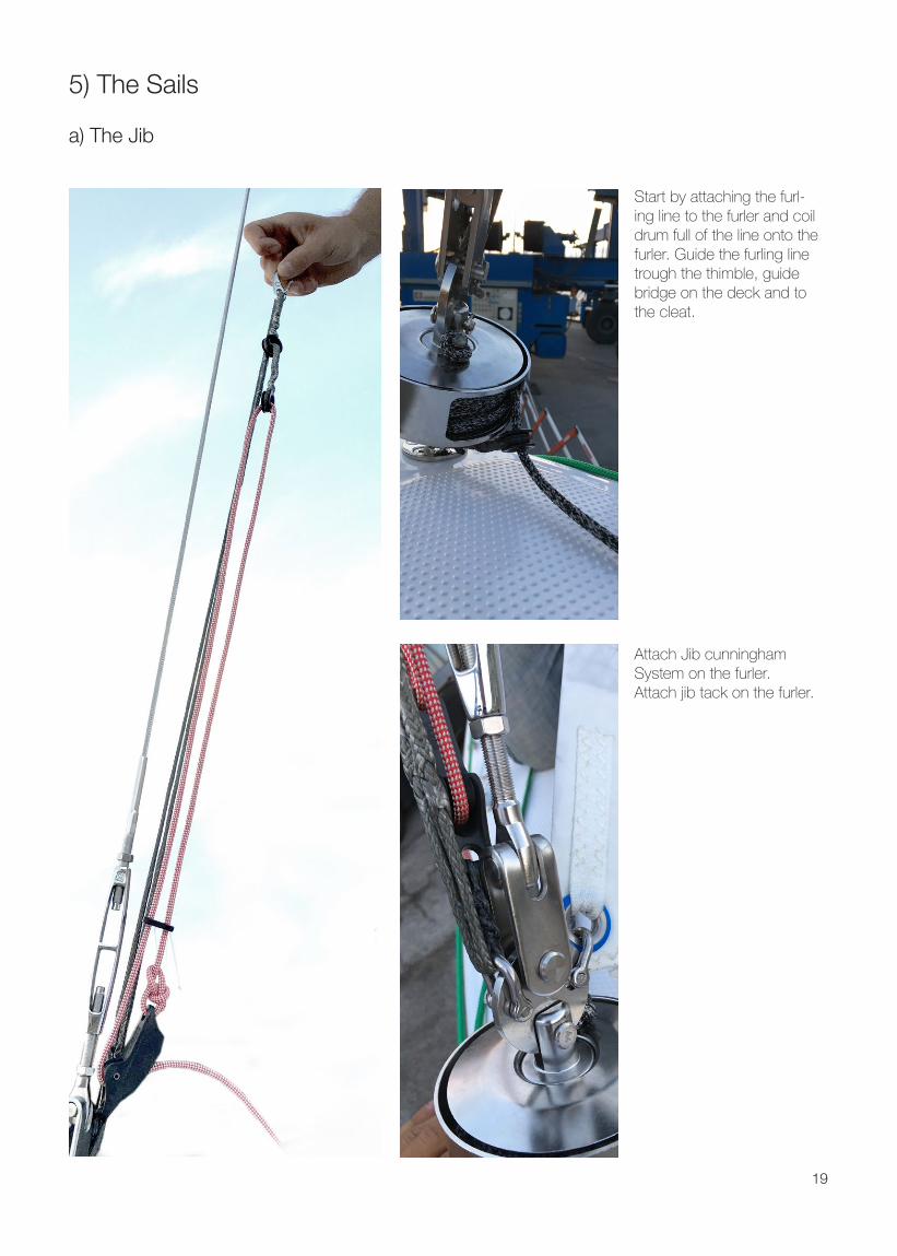
Start by attaching the furl-ing line to the furler and coil drum full of the line onto the furler. Guide the furling line trough the thimble, guide bridge on the deck and to the cleat.
Attach Jib cunningham System on the furler.Attach jib tack on the furler.

20
Use the composite shackle to attach both ends of the jib halyard on the jib head.
Close the top of the zipper and run the thin end of the jib halyard trough the zipped pocket.
Hoist the jib by pulling on the thin part of the jib halyard while closing the zipper as the sail is hoisted.

21
Hook the jib cunningham into the loop of the thick part of the jib halyard and put it under tension by pulling the jib cunningham control line. You can stow the excess line into the pocket in the protec-tive flap.
Attach the sheets on the jib clew and run them trough the lead blocks on the coach roof. Furl the jib by pulling the jib furling line and you are done.
22
b) The Mainsail
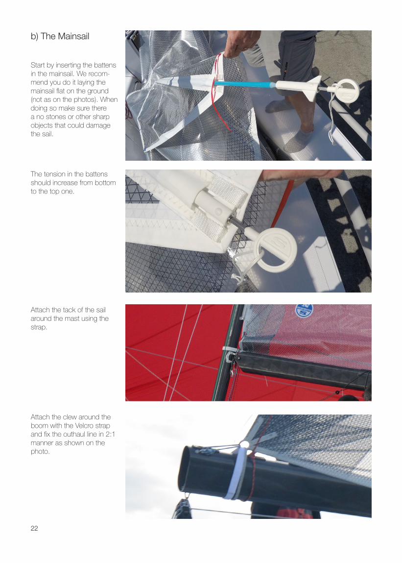
Start by inserting the battens in the mainsail. We recom-mend you do it laying the mainsail flat on the ground (not as on the photos). When doing so make sure there a no stones or other sharp objects that could damage the sail.
Attach the clew around the boom with the Velcro strap and fix the outhaul line in 2:1 manner as shown on the photo.
Attach the tack of the sail around the mast using the strap.
The tension in the battens should increase from bottom to the top one.

23
Run the cunnigham system trough dedicated eye on the mainsail. Attach the loop at the end on the dog bone fixed on the left side of the mast support.
Attach the 2:1 halyard and you are ready to hoist. Make sure that the Halyard is not twisted before you do so.

24
c) The Gennaker
Gennaker sheets are run trough the system that pro-vides maximum grip on the ratchet block. This allows the crew to hand trim the Gen-naker even in fresh breeze.

25
6) The keelThe 24 features fully retract-able composite keel with a lead insert at its bottom. This amongst other things allows you to literally beach the boat to the sandy beach (make sure there are no rocks or big stones though).
To operate the keel use stan-dard winch handle. You turn the handle Anticlockwise to raise the keel and Clockwise to lower it.
Use the inspection window on the winch cover to posi-tion the keel in the:UP: the red mark on the keel hoist rope is positioned over the keel winch axis.DOWN: green mark on the rope is in the same position.
Keel can ONLY be used in up or down position.

26
The keel pin should be inserted at all times when the boat is sailing. When insert-ing them you might have to move the keel head up and down until you find the right position. Remember the exact position of the green mark on the keel rope to simplify later insertions.
Keel head has a hole which should be aligned with the holes on the keel box to allow insertion of the pin.
Keel fin must always be resting on the trailer sup-port without any load on the winch during the transport.

27
6) The dataIf your 24 has the Elec-tric package she is also equipped with the Sentinel GPS/GSM tracker. Down-load the Sentinel marine app or login to web.sentinelmarine.net to get access to your boats data.
Like that you can follow your sailing trough the digital log book. Your data also allows you to participate in the 3rd party partners like the ww.sailingrecord.com
In the sentinel web applica-tion look for the two triangles which send the track straight to the sailing record
www.sailingrecord.com is hosting web based compe-titions amongst sailors. Use your Sentinel or otherwise acquired tracks to join the fun.