assembly instructions arf - tower hobbies. test fit the aileron servo in the 3mm plywood aileron...
TRANSCRIPT
WARRANTY
Tower Hobbies guarantees this kit to be free from defects in both material and workmanship at the date of purchase. Thiswarranty does not cover any component parts damaged by use or modification. In no case shall Tower Hobbies’ liabilityexceed the original cost of the purchased kit. Further, Tower Hobbies reserves the right to change or modify thiswarranty without notice.
In that Tower Hobbies has no control over the final assembly or material used for final assembly, no liability shall beassumed nor accepted for any damage resulting from the use by the user of the final user-assembled product. By the actof using the user-assembled product, the user accepts all resulting liability.
If the buyer is not prepared to accept the liability associated with the use of this product, the buyer is advised toreturn this kit immediately in new and unused condition to the place of purchase.
READ THROUGH THIS MANUAL COMPLETELY BEFORE STARTING CONSTRUCTION. IT CONTAINSIMPORTANT INSTRUCTIONS AND WARNINGS CONCERNING THE ASSEMBLY AND USE OF THIS MODEL.
© Copyright 2002 V 1.0 TOWZ1152 for TOWA1110
Tower HobbiesP.O. Box #90788
Champaign, IL 61826(800) 637-6050
www.towerhobbies.com
Wingspan: 62 in [1,550mm]
Wing Area: 698 sq in [45.0 sq dm]
Weight: 5 lbs [2,268 g] Length: 50.5 in [1,283mm]
Wing Loading: 17 oz/sq ft [52 g/sq dm]
Engine: .40 - .46 cu in [6.6 – 7.5cc] two-stroke
Radio: 4 channel
TOWER TRAINER 40 MKIIALMOST-READY-TO-FLY RADIO CONTROLLED MODEL AIRPLANE
ASSEMBLY INSTRUCTIONS
ARFARF
®
®
™

TABLE OF CONTENTSINTRODUCTION..............................................................2
ADDITIONAL ITEMS REQUIRED ...................................3
ENGINE RECOMMENDATIONS.................................3
RADIO RECOMMENDATIONS ...................................3
COVERING ACCESSORIES.......................................3
ADHESIVES AND ASSEMBLING SUPPLIES.................3
OPTIONAL SUPPLIES AND TOOLS ..............................3
PREPARATIONS ..............................................................3
ASSEMBLE THE WING...................................................4
JOIN THE WING.........................................................4
HOOK UP THE AILERONS ........................................7
ASSEMBLE THE FUSELAGE .......................................10
MOUNT THE STAB AND FIN ...................................10
INSTALL THE WING MOUNTING DOWELS................13
INSTALL THE FUEL TANK............................................14
MOUNT THE ENGINE ...................................................15
MOUNT THE LANDING GEAR .....................................17
PARTS LIST ................................................center section
FINAL ASSEMBLEY ......................................................19
HOOK UP THE CONTROLS ....................................20
INSTALL THE RADIO GEAR.....................................21
APPLY THE DECALS................................................23
PREPARE THE MODEL FOR FLIGHT..........................24
BALANCE THE MODEL (C.G.) .................................25
BALANCE THE MODEL LATERALLY .......................25
PREFLIGHT ...................................................................26
IDENTIFY YOUR MODEL.........................................26
CHARGE THE BATTERIES.......................................26
BALANCE PROPELLERS.........................................26
GROUND CHECK ....................................................26
RANGE CHECK........................................................26
ENGINE SAFETY PRECAUTIONS................................26
AMA SAFETY CODE (EXCERPTS)...............................27
CHECK LIST ..................................................................27
GETTING READY TO FLY.............................................28
USING RUBBER BANDS .........................................28
TAXIING ....................................................................28
TAKEOFF ..................................................................29
FLYING .....................................................................29
LANDING..................................................................29
FUEL MIXTURE ADJUSTMENTS.................................29
MODELING TERMS AND TRIVIA.................................30
INTRODUCTION
Thank you for purchasing our Tower Trainer 40 MKII ARF.This model has been specially created for you and otherfirst-time radio control modelers. The Tower Hobbies TowerTrainer 40 MKII ARF offers nearly all the excitement ofpiloting a real airplane…and develops skills that will takeyou anywhere you want in your new hobby.
SAFETY PRECAUTIONS
PROTECT YOUR MODEL, YOURSELF &OTHERS...FOLLOW THESE IMPORTANT SAFETY
PRECAUTIONS
1. Your Tower Trainer 40 MKII ARF should not beconsidered a toy, but rather a sophisticated, workingmodel that functions very much like a full-size airplane.Because of its performance capabilities, the Tower Trainer40 MKII ARF, if not assembled and operated correctly,could possibly cause injury to yourself or spectators anddamage property.
2. You must assemble the model according to theinstructions. Do not alter or modify the model, as doing somay result in an unsafe or unflyable model.
3. You must take time to assemble straight, true and strong.
4. You must use an R/C radio system that is in first-classcondition, and a correctly sized engine and components(fuel tank, wheels, etc.) throughout the assembly process.
5. You must properly install all R/C and other componentsso that the model operates properly on the ground and inthe air.
6. You must check the operation of the model before everyflight to insure that all equipment is operating and that themodel has remained structurally sound. Be sure to checkclevises or other connectors often and replace them if theyshow any signs of wear or fatigue.
7. If you are not already an experienced R/C pilot, youshould fly the model only with the help of a competent,experienced R/C pilot.
Remember: Take your time and follow the instructions toend up with a well-built model that is straight and true.
We, as the kit manufacturer, provide you with a topquality kit and instructions, but ultimately the quality andflyability of your finished model depends on how youassemble it; therefore, we cannot in any way guaranteethe performance of your completed model, and norepresentations are expressed or implied as to theperformance or safety of your completed model.
2

If you have not flown this type of model before, werecommend that you get the assistance of an experiencedpilot in your R/C club for your first flights. If you’re not amember of a club, your local hobby shop has informationabout clubs in your area whose membership includesexperienced pilots.
In addition to joining an R/C club, we strongly recommendyou join the AMA (Academy of Model Aeronautics). AMAmembership is required to fly at AMA sanctioned clubs.There are over 2,500 AMA chartered clubs across thecountry. Among other benefits, the AMA providesinsurance to its members who fly at sanctioned sites andevents. Additionally, training programs and instructors areavailable at AMA club sites to help you get started the rightway. Contact the AMA at the address or toll-free phonenumber below:
Academy of Model Aeronautics5151 East Memorial DriveMuncie, IN 47302-9252
Tele. (800) 435-9262Fax (765) 741-0057
Or via the Internet at: http://www.modelaircraft.org
ADDITIONAL ITEMS REQUIRED
This is the list of hardware and accessories required tofinish the Tower Trainer 40 MKII ARF. Order numbers areprovided in parentheses.
Engine Recommendations
TOWER HOBBIES 46 ABC [TOWG0146]OS® 40 LA [OSMG0041]OS 40 FX [OSMG0540]OS 46 LA [OSMG0046]OS 46 FX [OSMG0546]SUPER TIGRE® GS-40 Ring [SUPG0122]SUPER TIGRE GS-45 ABC [SUPG0150]
Radio Recommendations
FUTABA 4VF [FUTJ62**]
Covering accessories
Tower Custom Sealing Iron (TOWR3250)Top Flite® Hot Sock™ Iron Cover (TOPR2175)
ADHESIVES AND ASSEMBLING SUPPLIESIn addition to common household tools and hobby tools,this is the “short list” of the most important items requiredto assemble the Tower Trainer 40 MKII ARF. TowerHobbies Build-it™ CA and Epoxy glue are recommended.
❍ 2 oz. Tower Hobbies Build-it™ CA (TOWR3800)❍ 30-Minute Tower Hobbies Build-it Epoxy (TOWR3811)❍ 6-Minute Tower Hobbies Build-it Epoxy (TOWR3807)❍ Hobby Knife (HCAR0105), #11 Blades (HCAR0211)❍ Small T-pins (HCAR5100)❍ Builder’s triangle (HCAR0480)❍ Small Phillips and flat blade screwdrivers❍ Small metal file❍ Pliers with wire cutter (HCAR0630)❍ Threadlocker (GPMR6060)❍ RTV Silicone❍ Great Planes® Easy-Touch™ Bar Sander (GPMR6170)❍ Easy-Touch Sandpaper, 180 Grit (GPMR6184)
OPTIONAL SUPPLIES AND TOOLSHere is a list of optional supplies and tools mentioned inthe manual that will help you assemble the Tower Trainer40 MKII ARF.
❍ Great Planes CG Machine™ (GPMR2400)❍ Top Flite Precision Magnetic Prop Balancer™ (TOPQ5700)❍ Masking Tape (TOPR8018)❍ Epoxy Brushes (GPMR8060)❍ Mixing Sticks (GPMR8055)❍ Denatured Alcohol (for epoxy clean up)❍ Non-elastic monofilament or Kevlar fishing line
(K+SR4575)❍ Builder’s Triangle Set (HCAR0480) ❍ Masking Tape (TOPR8018)❍ Felt-Tip Marker (TOPQ2510)❍ Hobbico Servo Horn Drill (HCAR0698)❍ Great Planes AccuThrow™ Deflection Gauge (GPMR2405)❍ Great Planes Stick-on Weight (GPMQ4485)
PREPARATIONS❍ 1. Remove the major parts of the kit from the box (wings,fuselage, tail parts, etc.) and inspect them for damage. If anyparts are damaged or missing, contact Product Support at theaddress or telephone number listed in this manual.
❍ 2. Remove the masking tape and separate the aileronsfrom the wing, the rudder from the fin and the elevator fromthe stabilizer. Where necessary, use a covering iron with acovering sock to tighten the covering that may haveloosened during storage or from removing the maskingtape. Apply pressure over sheeted areas to thoroughlybond the covering to the wood.
3

❍ 1. In order to assemble the wing you will need thefollowing items as shown in the photo above.
#1 Right Wing Panel (1)#2 Left Wing Panel (1)#3 CA Hinges (8)#4 Wing Dihedral Braces (2)#5 Aileron Servo Tray (1) #6 Aileron Servo Tray Mounting Blocks (2)#7 Aileron Pushrods (2)#8 Faslinks (2)#9 Clevises (2)
#10 Nylon Torque Rod Horns (2)#11 Silicone Clevis Retainers (2)
❍ 2. In order to assemble the wing you will need the itemsshown in the photo above from your radio control system contents.
JOIN THE WING
❍ 3. Use 6-minute epoxy to glue both 3mm plywood wingjoiners together. Use weights or clamps to hold the joinersin place until the epoxy cures.
4
ASSEMBLE THE WING

❍ 4. Test fit the aileron servo in the 3mm plywood aileronservo tray. If necessary, trim the opening in the tray toaccommodate the servo. Once you are satisfied with the fit ofthe servo, remove it from the tray and set it aside for now.
❍ 5. Measure the width of your servo. Mark and cut 1/2 ofthis distance from the sheeting over the aileron servomounting area in both wing panels to accommodate 1/2 ofyour aileron servo.
❍ 6. The servo will be centered in the wing after the twopanels are joined. Test fit the servo into the cutout of both
the wing panels. Trim the root rib if necessary toaccommodate the servo and the servo wire. Prepare theleft wing panel the same way.
❍ 7. Trim the covering from the ends of the root ribs onboth wing panels. This is easily done with a sanding blockand medium-grit sandpaper as shown. Do both wingpanels at this time.
❍ 8. Draw a centerline on both sides of the plywood wingjoiner as shown.
❍ 9. Locate the two 8mm square x 38mm aileron servotray mounting blocks. Mark a centerline on each block.
Using the wing joiner as a guide, mark the wing dihedralangle on both of the aileron mounting blocks. Trim andsand to shape at this time.
Set the blocks aside for now.5

❍ 10. Test fit the wing joiner into one wing panel, then theother. Be certain the joiner is installed upright with thejoiner angled upward for wing dihedral. Also make sure thatthe joiner slides in all the way to the centerline. Test fit thewing panels together with the joiner. Make certain bothpanels fit well.
❍ 11. The measurement for this wing is 5-1/4” [133mm]plus/minus 1/2” [13mm] from the top of your table to thehighest point of the wing tip as shown in the photo. Tocheck that this is correct, join the two wing panels togetherwith the joiner in place. Lay the wing on a flat surface with onepanel flat on your bench or table. To do this you will need toallow the trailing edge of the wing to overhang the edge of yourtable in order to avoid the aileron torque rods as shown in thephotograph above. After making sure the root ribs are fittingtogether with no gaps on the top or bottom of the wing,measure the distance from the bench surface to the wing tip.
If this measurement is not 5-1/4” [133mm] plus/minus 1/2”[13mm] make adjustments in the plywood joiner. (It is possiblethat the joiner may require slight sanding to remove slivers ofwood or excess epoxy that may interfere with the fit).
❍ 12. Once satisfied with the fit of the joiner and the winghas the proper dihedral, it is time to glue the two panelstogether. First thoroughly coat the inside of both pocketswhere the joiner fits and one half of the joiner with 30-minute epoxy. Making certain the joiner is upright andinsert the coated end into one of the wing panels. Coat theother end of the joiner and both wing root ribs with theepoxy and join the two wing panels together.
❍ 13. Wipe away any epoxy that squeezes out frombetween the wing halves with paper towels saturated withalcohol. Use masking tape on the top and bottom to holdthe wing together as shown. Be certain the root ribs on theends of the wing panels accurately align. Again, wipe awayexcess epoxy and do not disturb the wing until the epoxyhas fully hardened.
6

HOOK UP THE AILERONS
Do the left wing first so the assembly matches thephotographs the first time through. You can do one wing ata time, or work on them together.
❍ ❍ 1. Take a close look at the supplied hinges. The abovephoto has this slot highlighted and must be inserted intoplace in the proper direction as indicated in the photo.
❍ ❍ 2. Test fit the hinges in the hinge slots of the aileronand the wing. If you have difficulty inserting the hinges,insert a #11 blade into the slot and carefully move it backand forth to slightly widen the slot. Test fit the aileron to thewing with the hinges.
❍ ❍ 3. If the hinges don’t remain centered, stick a pin throughthe middle of the hinge to hold it in position as shown.
❍ ❍ 4. Coat the “arm” portion of the aileron torque rodthat slips inside the aileron and the groove and the hole inthe aileron where the torque rod fits with 30-minute epoxy.Tip: You may want to use a toothpick to get epoxy into thehole drilled in the aileron for the aileron torque rod.
❍ ❍ Use a strip of waxed paper between the torque rodand the wing to keep from gluing the torque rod to thewing. Be careful to keep the epoxy out of the area wherethe rod enters the trailing edge of the wing. Place a smallamount of petroleum jelly in this area. Join the aileron to thewing and the torque rod with the hinges. Wipe away excessepoxy with a tissue saturated with alcohol.
❍ ❍ 5. Remove the T-pins if you’ve used any. Adjust theaileron so there is a small gap—just enough to see lightthrough or to slip a piece of paper through—between theaileron and the wing.
❍ ❍ 6. Apply six drops of thin CA to the top and bottomof each hinge. Do not use CA accelerator. After the CA hasfully hardened, test the hinges by pulling on the aileron. Goback and install the other aileron in the same manner.
7

❍ 7. Glue the two 8mm square x 38mm aileron servo traymounting blocks that you cut to shape earlier to the aileronservo tray. Be sure that you glue the flat side of the blocksto the aileron servo mounting tray.
❍ 8. Place the servo into this assembly and test fit this intolocation in the center of the wing. Mark the location of themounting blocks with a felt tipped pen.
Use a sharp #11 blade to cut the covering from the wingfor the aileron servo mount. Be extremely careful to cutonly the covering and do not cut into the balsa wood underthe covering.
Be sure to allow room for the aileron servo lead. Ifnecessary, cut away a small area for the lead to exit thewing as shown. Glue the servo mount to the wing with 6-minute epoxy.
❍ 9. Assemble the servo using the four servo grommetsand four brass eyelets as shown in the sketch above. Insertthe servo into the mount and mark the location for the 4screws. Remove the servo and drill 1/16” [1.6mm] holesthrough the servo mount for the servo mounting screws.
Run the servo mounting screws into the mount and thenremove them, which will make threads in the wooden servomount. Add a drop of thin CA to the holes and allow to fullyharden, thus hardening the threads for more strength. Note: Do not apply the thin CA with the servo in place asyou will glue it to the mount. Mount the aileron servo usingthe servo mounting screws.
❍ 10. Thread the nylon torque rod horns onto bothaileron torque rods until the top of the horn is even with thetop of the torque rod as shown in the photograph.
❍ 11. Make a two-arm servo arm by cutting two arms offa four-arm servo arm. Enlarge the outer holes in the armwith a Hobbico Servo Horn Drill (or a #48 or 5/64” [2mm]drill bit).
How to cut covering from balsa.To avoid cutting into the balsa, use a soldering ironinstead of a hobby knife to cut the covering from the stab.The tip of the soldering iron doesn’t have to be sharp, buta fine tip does work best. Allow the iron to heat fully. Usea straightedge to guide the soldering iron at a rate that willjust melt the covering and not burn into the wood. Goingtoo slowly burns into the wood and weakens it. The hotterthe soldering iron, the faster it must travel to melt a finecut. Peel off the covering.
8

❍ 12. Assemble the two aileron pushrods made from two200mm wire pushrods, clevises, and silicone retainers.To make the pushrods, thread the clevises onto the wirepushrods approximately 25 full turns.
❍ 13. Center the servo arm on the servo. Attach the clevis tothe torque rod horn; hold the aileron level with the bottom ofthe wing, using a straight edge to assure accuracy. Mark thelocation where the wire crosses the hole in the servo arm. Atthis location bend the wire 90 degrees.
❍ 14. After bending the pushrods at your mark, slide theFaslink over the wire and snap it into place on the pushrod.
❍ Cut the wire that extends beyond the Faslink; be certainto leave 1/16” [1.6mm] of wire protruding from the Faslinkas shown in the photograph.
❍ 15. Install the remaining pushrod in the same manner.The above photo shows how your assembly should lookwhen finished.
9

MOUNT THE STABILIZER AND FIN
❍ 1. In order to complete this section you will need thefollowing items as shown in the photograph above. You willalso need the wing (not shown) for alignment purposes.
#1 Fuselage (1)#2 Stabilizer (Stab) (1)#3 Elevator (1)#4 Fin (1)#5 Rudder (1)#6 CA Hinges (7)
❍ 2. Test fit the hinges into hinge slots in the stabilizerand elevator and the fin and rudder. If necessary insert a#11 blade into the hinge slots and run it back and forth toenlarge them slightly. Important Note: Remember to insert the hinges with thecut running the correct direction.
❍ 3. Use a hobby knife with a sharp #11 blade and cut thecovering from the openings on both sides of the fuselage forthe stab. Also cut the covering from the opening in the top ofthe fuselage for the fin. Remove the elevator from the stab.
❍ 4. Taking accurate measurements, locate the center ofthe stab along the trailing edge. Slide the stab into thefuselage and center it over the aft end of the fuselage.Insert a T-pin through the stab and into the fuse at thelocation shown in the photograph above. This will hold it inplace but will still allow for correct alignment.
10
ASSEMBLE THE FUSELAGE

❍ 5. Support the model with a small stand or cardboardbox. Place the wing into the wing saddle on the top of thefuselage. Stand five to ten feet behind the model and viewthe stab and wing. If the stab and wing align with eachother, proceed to the next step. If the stab and wing do notalign, place a small weight on the “high” side of the stab tobring it into alignment. If much weight is required, removethe stab and carefully sand the slot in the fuselage wherethe stab fits until it aligns with the wing.
❍ 6. Stick a T-pin into the top of the fuselage centered in themiddle stringer over the firewall. Tie a small loop in one end ofa piece of non-elastic string (K & S #801 Kevlar thread;K&SR4575). Slip the loop in the string over the T-pin.
❍ 7. Fold a piece of masking tape over the other end ofthe string and draw an arrow on it. Slide the tape along thestring and align the arrow with one end of the stab asshown in the photograph.
Swing the string over to the same position on the other endof the stab. If the distance is not equal move the stab ½way to the arrow then move the string back to the otherside to check alignment. Adjust the stab in this manneruntil both sides are equal.
❍ 8. When you are satisfied with the alignment of the stabuse a fine-point felt-tip pen such as a Top Flite Panel LinePen (TOPQ2510) to mark the outline of the fuselage ontothe top and bottom of the stab.
11
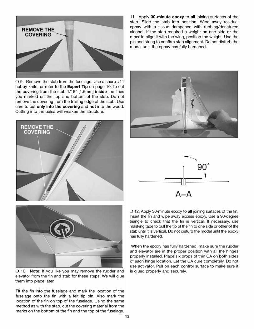
❍ 9. Remove the stab from the fuselage. Use a sharp #11hobby knife, or refer to the Expert Tip on page 10, to cutthe covering from the stab 1/16” [1.6mm] inside the linesyou marked on the top and bottom of the stab. Do notremove the covering from the trailing edge of the stab. Usecare to cut only into the covering and not into the wood.Cutting into the balsa will weaken the structure.
❍ 10. Note: If you like you may remove the rudder andelevator from the fin and stab for these steps. We will gluethem into place later.
Fit the fin into the fuselage and mark the location of thefuselage onto the fin with a felt tip pin. Also mark thelocation of the fin on top of the fuselage. Using the samemethod as with the stab, cut the covering material from themarks on the bottom of the fin and the top of the fuselage.
11. Apply 30-minute epoxy to all joining surfaces of thestab. Slide the stab into position. Wipe away residualepoxy with a tissue dampened with rubbing/denaturedalcohol. If the stab required a weight on one side or theother to align it with the wing, position the weight. Use thepin and string to confirm stab alignment. Do not disturb themodel until the epoxy has fully hardened.
❍ 12. Apply 30-minute epoxy to all joining surfaces of the fin.Insert the fin and wipe away excess epoxy. Use a 90-degreetriangle to check that the fin is vertical. If necessary, usemasking tape to pull the tip of the fin to one side or other of thestab until it is vertical. Do not disturb the model until the epoxyhas fully hardened.
When the epoxy has fully hardened, make sure the rudderand elevator are in the proper position with all the hingesproperly installed. Place six drops of thin CA on both sidesof each hinge location. Let the CA cure completely. Do notuse activator. Pull on each control surface to make sure itis glued properly and securely.
12
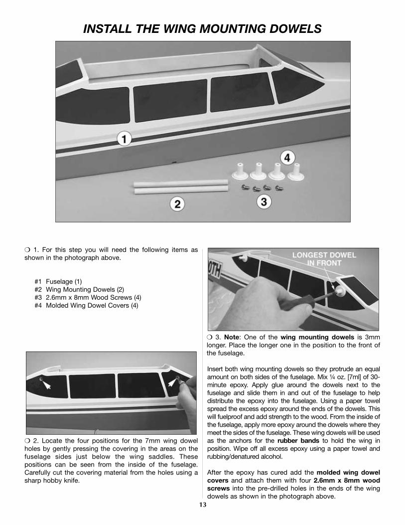
❍ 1. For this step you will need the following items asshown in the photograph above.
#1 Fuselage (1)#2 Wing Mounting Dowels (2)#3 2.6mm x 8mm Wood Screws (4)#4 Molded Wing Dowel Covers (4)
❍ 2. Locate the four positions for the 7mm wing dowelholes by gently pressing the covering in the areas on thefuselage sides just below the wing saddles. Thesepositions can be seen from the inside of the fuselage.Carefully cut the covering material from the holes using asharp hobby knife.
❍ 3. Note: One of the wing mounting dowels is 3mmlonger. Place the longer one in the position to the front ofthe fuselage.
Insert both wing mounting dowels so they protrude an equalamount on both sides of the fuselage. Mix ¼ oz. [7ml] of 30-minute epoxy. Apply glue around the dowels next to thefuselage and slide them in and out of the fuselage to helpdistribute the epoxy into the fuselage. Using a paper towelspread the excess epoxy around the ends of the dowels. Thiswill fuelproof and add strength to the wood. From the inside ofthe fuselage, apply more epoxy around the dowels where theymeet the sides of the fuselage. These wing dowels will be usedas the anchors for the rubber bands to hold the wing inposition. Wipe off all excess epoxy using a paper towel andrubbing/denatured alcohol.
After the epoxy has cured add the molded wing dowelcovers and attach them with four 2.6mm x 8mm woodscrews into the pre-drilled holes in the ends of the wingdowels as shown in the photograph above.
13
INSTALL THE WING MOUNTING DOWELS

❍ 1. To complete this step you will need the following itemsas shown in the photograph above.
#1 Fuel Tank (1)#2 Clunk (1)#3 Fuel Pickup Tube (1)#4 Vent Tube (1)#5 Fuel Line for Pickup (1)#6 Stopper with Hardware (1)#7 Fuel Line (1)
Note: The fuel tank parts shown in the photo are placedinside the tank at the factory.
❍ 2. Assemble the stopper, tubes, and clunk as shownin the photograph. Bend the vent tube so it is just below
the top of the tank and then insert this assembly into in thetank. Tighten the screw to expand the stopper, thus sealingthe tank. Be certain the clunk at the end of the fuel lineinside the tank does not contact the rear of the tank.Otherwise, the line may become stuck above the fuel leveland discontinue fuel flow.
Remember (or use a felt-tip pen to mark) which tube is thefuel pick-up tube and which tube is the vent (that will beconnected to the pressure fitting on the muffler). Place thefuel lines on the vent and fuel pick-up tubes at this time.
❍ 3. Install the tank in the fuselage with the neck of thetank inserted into the hole in the firewall. Secure the tankinto place with RTV silicone or Zap-A-Dap-A-Goo(PAAR3200) around the stopper. Then slip the tank intoplace. Also put a bead of silicone around the stopper onthe front of the firewall.
14
INSTALL THE FUEL TANK

❍ 1. To complete this step you will need the following itemsas shown in the photograph above.
#1 Fuselage (1)#2 Muffler for Engine (1) (not supplied)#3 Engine (1) (not supplied)#4 Spinner (1)#5 Propeller (1) (not supplied)#6 Engine Mount, .40 size (1)#7 Engine Mounting Straps (2)#8 4mm x 20mm Machine Screws (4)#9 4mm x 25mm Machine Screws (4)
#10 4mm Lock Washers (8)#11 4mm Nuts (4)
❍ 2. Secure the engine mount to the firewall with four 4mmx 20mm machine screws and 4mm lock washers. Use
Threadlocker on the machine screws to keep them fromvibrating loose. Blind nuts are pre-installed behind the firewall.
❍ 3. The engine’s mounting lugs are “sandwiched” betweenthe engine mount and the engine mount straps. Begin byplacing four 4mm lock washers onto each of the four 4mm x25mm machine screws.
Pass two of the screws through the two engine mount strapsand place the screws through the back holes of the enginemount as shown in the photograph. Place two 4mm nuts intothe recesses on the bottom of the engine mount. Start thescrews, but do not tighten them at this time.
15
MOUNT THE ENGINE
NOTE: The engine in your airplane is mounted slightly different from that of most R/C aircraft. This is done to allow the use of manydifferent types of engines. It also allows a “no-drill” approach to ease the engine installation. Read through the procedure andunderstand all the steps before actually performing them.

❍ 4. With the engine in place, install the remaining two4mm x 25mm machine screws, 4mm lock washers, and4mm nuts in place at the front of the engine mount asshown in the photograph. Do not tighten the screws at thistime to allow for the positioning of the engine.
❍ 5. Install the spinner backplate, propeller, propeller washerand the propeller nut onto the engine. Turn the propellercounterclockwise until it is against the smallest pins on thebackplate. Keep the propeller horizontal when the engine isagainst its compression [the point at which you feel resistancewhen you turn the crankshaft counterclockwise]. Use anadjustable wrench to securely tighten the propeller nut.
❍ 6. Measure the distance from the spinner backplate to thefirewall. It should be 3-3/4” [95mm] on both sides of thespinner backplate. Adjust the engine if needed and tighten thescrews evenly, using Threadlocker on the screws and the nutsto secure the engine to the mount. Following the enginemanufacturer’s instructions, install the muffler to the engine.
❍ 7. Attach the silicone fuel lines to the engine. The lineyou marked “Vent” should be attached to the muffler. Theother line will be attached to the needle valve. Make surethere are no sharp bends in the lines. If so, carefully adjustthe lines to allow for a smooth flowing bend to theappropriate fitting of the engine.
8. Attach the spinner cone with the screws provided. Becareful not to overtighten these screws. They are threadedinto plastic that can strip out if they are over tightened.
16

❍ 1. To complete this step you will need the following itemsas shown in the photograph above.
#1 Fuselage (1)#2 Main Landing Gear (2)#3 Nose Gear (1)#4 Wheels (3)#5 4mm x 12mm Phillips Head Screws (2)#6 Nose Gear Bearing Block (1)#7 4mm Wheel Collars (8)#8 3mm x 8mm Phillips Head Set Screw (1)
(For Nose Gear Steering Arm Only)#9 3mm x 5mm Phillips Head Set Screw (7)
#10 4mm Flat Washers (2)#11 Landing Gear Straps (2)#12 3mm X 10mm Phillips Head Wood Screws (4)#13 Nylon Steering Arm (1)#14 Screw Lock Pushrod Connector Assembly (1)
❍ 2. Test fit the two main landing gear wires into the pre-drilled holes inside the channel located in the bottom
of the fuselage. If they will not go in easily, drill out the twoholes using a 5/32” [4mm] drill bit. Next, use the drill bit orhobby knife to bevel the inside corners of the holes so thatthe bend in the wire will seat fully into the holes and thewire will be flush with the bottom of the fuselage. Place thelanding gear wires into the channel. Look carefully and youwill find four pre-drilled holes under the covering. They canbe seen in the photograph.
❍ 3. At the locations of the pre-drilled holes attach thenylon landing gear straps to the fuselage using the four3mm x 10mm Phillips head wood screws and the nylonlanding gear straps as shown in the above photograph.
17
MOUNT THE LANDING GEAR

❍ 4. Install the nose gear by attaching the nose gearbearing bracket to the firewall with two 4mm x 12mmPhillips head screws and the two 4mm washers whichmust go behind the bracket so they act as spacers asshown in the photograph above. Apply Threadlocker tothese screws before installing them.
❍ 5. The steering arm should be cut off as shown in theabove photograph. Place one of the wheel collars into thesteering arm base, making sure the threaded hole for theset screw is aligned with the hole in the steering arm baseas shown in the photograph above. The 3mm x 8mmPhillips head set screw is then placed into the wheelcollar through the hole in the base of the steering arm.
❍ 6. Place the screw lock pushrod connector onto thesteering arm exactly as shown in the above photograph.Important Note: The screw lock pushrod connector isassembled in the bag. In order to place it onto the steering armyou will need to remove the wheel-type nut and the washer onthe end of the unit. Insert the threaded stem of the unit into thehole on the steering arm in the manner shown in the
photograph. Place the washer on the threaded stem followedby the wheel-type nut. Apply Threadlocker to the threadedstem and then gently tighten the nut. It is important not toovertighten this nut; this would not allow the screw lockpushrod connector to rotate on the steering arm while inoperation. Adjust the tightness of the nut and test theconnector’s ability to rotate but still be somewhat tight. Whenyou are satisfied with this adjustment place a small amount ofThreadlocker on the top of the nut and allow it to wick downinto the threads.
❍ 7. Place another wheel collar with a 3mm x 5mmPhillips head set screw onto the nose gear wire theninsert the nose gear wire into the nose gear bearingbracket. As you slide it through the bearing bracket, holdthe assembled steering arm in place and slide the nosegear through the steering arm and into the hole in thebottom of the engine mount. Note that the existing flat spoton the nose gear wire is facing forward. When you have thenose gear installed tighten the two Phillips head set screwsin the wheel collars to complete the installation.
❍ 8. Place a wheel collar and a wheel on the nose gear andlanding gear axles. Add the second wheel collar on the outsideof the wheel to each axle. Center the wheel on the axles asshown in the photograph. Mark the location of the outer wheelcollar on the axles with a felt tipped pen. Remove the wheelcollars and wheels. Then file or grind a 1/4” [6mm] flat spot onthe axles of the main and nose gear at the locations youmarked. This is done to prevent the wheel collar from turningor becoming loose during flight. Secure the 3 wheels on theaxles using the 3mm x 5mm Phillips head set screws in thewheel collars, using Threadlocker on the set screws to holdthem securely in place.
Double check all the wheels to make sure they still spinfreely. If not, move the inner wheel collar away from thewheel slightly and retighten the screw.
18

#1 Servos (3)#2 Receiver (1)#3 Switch (1)#4 Rubber Grommets (12)
#5 Brass Eyelets (12)#6 Servo Mounting Screws (12)#7 Aileron Extension Wire (1)#8 Receiver Battery (1)
19
FINAL ASSEMBLY
#1 Protective Foam (2)#2 Faslinks (2)#3 Screw Lock Pushrod Connector (1)#4 Silicone Clevis Retainers (3)#5 Clevises (3)#6 Control Horn Backplates (2)#7 Control Horns (2)#8 2mm x 14mm Phillips Head Screws (4)
#9 680mm Threaded Elevator-Rudder Pushrods (2)#10 Battery/Receiver Tray (1)#11 2.6mm x 8mm Wood Screws (4)#12 105mm Threaded One End Throttle Pushrod (1)#13 105mm Un-threaded Steering Pushrod (1)#14 Plastic Steering/Throttle Pushrod Guide Tubes (2)#15 10mm x 13mm x 80mm Balsa Pushrod Support (1)#16 Hook and Loop Material (2)
To complete this step you will need the following items, as shown in the photograph above.
The items shown in the above photograph will also be needed from the radio system.

HOOK UP THE CONTROLS
❍ 1. There is a 5mm hole in the firewall for the pushrodguide tube that will align with the throttle arm on most two-stroke engines. Use medium sandpaper to roughen bothplastic pushrod guide tubes. Insert one pushrod guide tubethrough the hole in the firewall for the throttle, and the otherfor the steering pushrod guide tube.
❍ 2. Thread a nylon clevis 25 full turns onto the 500mmthreaded throttle pushrod wire. Slip a silicone retainerover the clevis. Insert the pushrod with the clevis all theway into the throttle pushrod guide tube and connect theclevis to the throttle arm on the engine as shown in thephotograph above.
❍ 3. Run the un-threaded 500mm steering pushrod throughthe Screw Lock Pushrod Connector and continue pushing it allthe way into the steering rod guide tube. Position the pushrodguide tubes to extend approximately 1/8” [3mm] past thefirewall and glue them into place using 6-minute epoxy.
❍ 4. Screw two nylon clevises 25 full turns onto the two680mm threaded wire pushrods. Slip silicone retainers overthe clevises.
Slit the covering material where the guide tubes exit thefuselage with a hobby knife. The location of the ruddertube exit is on top of the fuse next to the fin and theelevator tube exit is located on the same side of fuse underthe stab. After you have made your cuts, slide thepushrods through the guide tubes. Connect the clevises tothe control horns placing them in the second hole fromthe end of the horn as shown.
❍ 5. Position the control horns on the elevator and rudderas shown in the photograph. The row of holes in the hornsshould be over the hinge line. If necessary small bendsmay be made in the pushrods to position them with thecontrol surfaces. Mark the locations of the holes in thebase of the control horns on the elevator and rudder. Atthese locations drill 5/64” [2mm] holes through the elevatorand rudder for mounting the control horns with 2mm x14mm phillips head screws, and then mount the controlhorns using the screws and the nylon backing plates on theother side of the control surfaces.
20

INSTALL THE RADIO GEAR
Elevator Arm Throttle Arm Rudder/Steering Arm
❍ 1. You must modify 3 servo arms to be used in thissection. Starting with the 4 armed servo arms supplied withyour radio system, modify them exactly as shown in theabove illustration. Enlarge the holes in the locations shownwith a Hobbico Servo Horn Drill (or a #48 or 5/64" [2mm]drill bit). Note: You may wish to trim the excess material from the armsas shown in the illustration and the following photographs.
❍ 2. Place the grommets and brass eyelets on the threeservos using the diagram above as a guide. Place theservos in the servo tray in the orientation shown in thefollowing photographs.
❍ 3. With your servo arms aligned at 90-degrees to theservos, position the servos so the holes in the servo arms,the holes you enlarged, cross the elevator and rudderpushrods. Carefully mark on the servo tray the fourlocations of each servo for the servo mounting screws. Atthese locations drill 1/16” [1.6mm] holes through the servotray. Install the servo mounting screws and then removethem, creating threads in the wood at all the locations. Adda drop of thin CA to each hole and allow it to harden (it isbest to take the servos out of the tray while doing this toavoid gluing the servos to the tray). Reposition the servosand mount them to the tray with the screws.
❍ 4. With the servos mounted into place, carefully centerthe rudder with the fin and the elevator with the stab. Whilethe control surfaces are centered, use a felt-tip pin to placea mark on the pushrod wire at the location of the hole in theservo arm as shown in the above photograph.
❍ 5. Use pliers to make a 90-degree bend at the marks.Disconnect the clevises from the elevator and ruddercontrol horns. Remove the servo arms from the servos andrun the pushrod through the hole in the servo arm from thebottom of the arm. Place a nylon Faslink to each pushrod,and then cut the wire with 1/16” [1.5mm] protruding fromthe Faslinks. Reattach the clevises to the control horns.
Reinstall the elevator servo arm on the servo with the screw.
Use a hobby knife with a sharp blade and cut the steeringpushrod guide tube at the location shown in the abovephotograph. Do not cut the steering pushrod at this time.
21

❍ 6. Carefully align the nose wheel as straight as possible.Align the steering pushrod with the second hole (out fromthe center) in the rudder servo arm and place a mark on thesteering pushrod as shown in the above photograph. Asyou did with the previous pushrods, make a 90-degreebend at the mark, install the servo arm and the Faslink, andcut off the excess steering push rod. Put the rudder/nosegear steering arm on the servo with the screw.
❍ 7. Install the throttle servo into the servo tray as shownabove using the same method used to mount the previoustwo servos with the servo mounting screws. Center thethrottle servo arm on the throttle servo as shown in theabove photograph.
Cut the guide tube using a sharp hobby knife at thelocation in the photograph. Remove the throttle servo armand install the screw lock pushrod connector in the lasthole on the servo arm. Slip the throttle pushrod into thescrew lock pushrod connector and reinstall the servo armonto the servo with the screw. Before tightening the screw lock pushrod connector lookinside the carburetor on the engine and move the throttlepushrod until the barrel of the carburetor is ½ open. Withthe throttle servo arm still centered on the servo, tightenthe screw on top of the screw lock pushrod connector.Using the above photograph as a reference, cut off theexcess throttle pushrod but leave a minimum of ½” (13mm)of excess rod for adjustments later.
❍ 8. Install the battery/receiver mounting plate into thefuselage using four 2.6mm x 8mm wood screws as shownin the above photograph. Note: You may place the supplied hook and loop materialinto the battery/receiver mounting plate prior to mountingthe plate into the fuselage. It is a bit more difficult if youwait to do this when you mount the receiver and battery.Refer to step #10 for location.
❍ 9. Locate the cutout for the on/off switch on the leftside of the fuselage, away from your engine exhaust andcut the covering from this cutout. Remove the cover platefrom the radio system on/off switch and use it as a patternto drill the two holes on either side of the cutout. This willallow you to mount the on/off switch by placing the twoscrews back into the cover plate and placing them throughthe fuselage side. Hold the on/off switch in place andreinsert and tighten the two screws in the on/off switch.
22

❍ 10. Connect the aileron extension, servo leads, batteryand switch wires to the receiver as directed by your radiosystem manual. Wrap both the battery pack and receiver inthe supplied protective foam rubber to protect them fromvibration. Secure both the battery pack and receiver in themodel by placing the supplied hook and loop materialthrough the slots in the battery/receiver mounting plate andthen around the battery and receiver.
❍ 11. Make an antenna strain relief from one of the cut-offservo arms and install it on the antenna. Route the receiverantenna out of the fuselage as close to the receiver as youcan by drilling a 5/64” (2mm) hole in the side of thefuselage and running the antenna through the side of thefuselage. Connect the antenna to a hook made fromanother leftover servo arm that was connected to a rubberband and a T-pin inserted into the top of the fin.
❍ 12. Make a pushrod guide tube support by using thesupplied 10mm x 13mm x 80mm balsa material. Place itinto the fuse as shown in the photograph above and markthe locations of the throttle and steering guide tubes. Cut,sand, or file a V or notch at these locations. Use sandpaperto roughen the outer surface of the tubes where they meetthe guide tube support.
Reposition the guide tube support making sure the tubes restin the notches and do not bind or put pressure on thepushrods. When satisfied with the fit, glue the support intoplace and glue the guide tubes to the support using 6-minuteepoxy. Be careful not to get glue in the opening of the guidetube or on the pushrod.
APPLY THE DECALS
❍ 1. Use scissors or a sharp hobby knife to cut the decalsfrom the sheet.
❍ 2. Be certain the model is clean and free from oilyfingerprints and dust. Prepare a dishpan or small bucketwith a mixture of liquid dish soap and warm water-aboutone teaspoon of soap per gallon of water. Submerse thedecal in the soap and water and peel off the paper backing.Note: Even though the decals have a "sticky-back" and arenot the water transfer type, submersing them in soap &water allows accurate positioning and reduces air bubblesunderneath.
❍ 3. Position decal on the model where desired. Holdingthe decal down, use a paper towel to wipe most of thewater away.
❍ 4. Use a piece of soft balsa or something similar tosqueegee remaining water from under the decal. Apply therest of the decals the same way.
23
PREPARE THE MODEL FOR FLIGHT
Check the Control Surface Movements
❍ 1. Turn on the transmitter and receiver and center thetrims on the transmitter. If necessary, remove the servoarms from the servos and reposition them so they arecentered. Reinstall the screws that hold on the servo arms.
❍ 2. With the transmitter and receiver still on, check all thecontrol surfaces to see if they are centered. Use a straightedge to help get them set correctly. If necessary, adjust theclevises on the pushrods to center the control surfaces.
❍ 3. Make certain that the control surfaces and thecarburetor respond in the correct direction as shown in thediagram above. If any of the controls respond in the wrongdirection, use the servo reversing switches in thetransmitter to reverse the servos connected to thosecontrols. Be certain the control surfaces have remainedcentered. Re-adjust if necessary.
For added safety and convenience, the throttle should beset up so that the engine can be stopped using the throttletrim. To do this remove the clevis from the carburetor armand move the throttle pushrod so that the carburetor iscompletely closed with the throttle stick and trim lever onthe transmitter fully back. Next, adjust the clevis so thatwhen the clevis is connected the carburetor barrel is in thefully closed position. Then test the trim lever by advancingit to full. This will be a fast idle position with the carburetorbarrel open slightly [about 1/32” or .8mm].
Now move the throttle stick forward to full. Make sure thatthe carburetor barrel opens all the way. If it doesn’t openfar enough or opens too far [bending the rod] move thepushrod and screw lock pushrod connector in or out onthe servo arm and/or the clevis on the carburetor arm togain or reduce movement. The throw will be correct whenthe carburetor barrel will stop fully open at the same timethe throttle stick reaches full. With the throttle set upproperly, you should be able to run the engine with the trimlever set midway to the full position [adjusted for a smoothbut slow idle]. Then when it is time to stop the engine,simply pull back the trim to close the carburetor and theengine will stop running.
Set the Control Throws
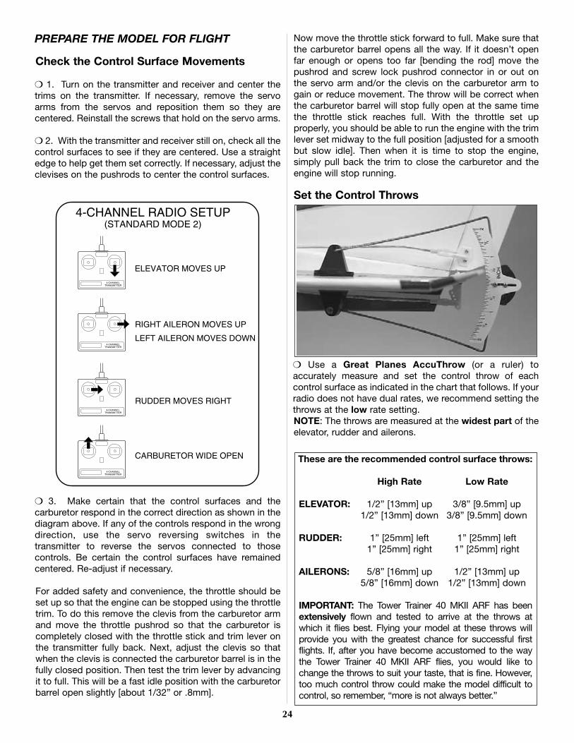
❍ Use a Great Planes AccuThrow (or a ruler) toaccurately measure and set the control throw of eachcontrol surface as indicated in the chart that follows. If yourradio does not have dual rates, we recommend setting thethrows at the low rate setting.NOTE: The throws are measured at the widest part of theelevator, rudder and ailerons.
These are the recommended control surface throws:
High Rate Low Rate
ELEVATOR: 1/2” [13mm] up 3/8” [9.5mm] up1/2” [13mm] down 3/8” [9.5mm] down
RUDDER: 1” [25mm] left 1” [25mm] left1” [25mm] right 1” [25mm] right
AILERONS: 5/8” [16mm] up 1/2” [13mm] up5/8” [16mm] down 1/2” [13mm] down
IMPORTANT: The Tower Trainer 40 MKII ARF has beenextensively flown and tested to arrive at the throws atwhich it flies best. Flying your model at these throws willprovide you with the greatest chance for successful firstflights. If, after you have become accustomed to the waythe Tower Trainer 40 MKII ARF flies, you would like tochange the throws to suit your taste, that is fine. However,too much control throw could make the model difficult tocontrol, so remember, “more is not always better.”
24

Balance the Model (C.G.)
At this stage the model should be in ready-to-fly conditionwith all of the systems in place including the engine,landing gear, and the radio system.
❍ 1. Use a felt-tip pen or 1/8”-wide tape to accurately markthe C.G. on the bottom of the wing on both sides of thefuselage. The C.G. is located 3-1/2“ [89 mm] back from theleading edge of the wing. This is where your model shouldbalance for your first flights. Later, you may wish toexperiment by shifting the C.G. up to 1/4” [6 mm] forwardor 1/4” [6 mm] back to change the flying characteristics.Moving the C.G. forward may improve the smoothness andstability, but it may then require more speed for takeoff andmake it more difficult to slow for landing. Moving the C.G.aft makes the model more maneuverable, but could alsocause it to become too difficult for you to control. In anycase, start at the location we recommend and do not at anytime balance your model outside the recommended range.
❍ 2. With the wing attached to the fuselage, all parts of themodel installed (ready to fly) and an empty fuel tank, placethe model on a Great Planes CG Machine (GPMR2400),or lift it at the balance point you marked.
❍ 3. If the tail drops, the model is “tail heavy” and thebattery pack and/or receiver must be shifted forward orweight must be added to the nose to balance. If the nosedrops, the model is “nose heavy” and the battery packand/or receiver must be shifted to the rear or weight mustbe added to the tail to balance. If possible, relocate thebattery pack and receiver to minimize or eliminate anyadditional ballast required. If additional weight is required,nose weight may be easily added by using a “spinnerweight” (GPMQ4645 for the 1 oz. weight, or GPMQ4646 forthe 2 oz. weight). If spinner weight is not practical or is notenough, use Great Planes (GPMQ4485) “stick-on” lead. Agood place to add stick-on nose weight is to the firewall.
Begin by placing incrementally increasing amounts ofweight on the fuselage over the firewall until the modelbalances. Once you have determined the amount of weightrequired, it can be permanently attached. If required, tailweight may be added by cutting open the bottom of thefuselage and gluing it permanently inside.
Note: Do not rely upon the adhesive on the back of thelead weight to permanently hold it in place. Over time, fueland exhaust residue may soften the adhesive and causethe weight to fall off. Use #2 sheet metal screws, RTVsilicone or epoxy to permanently hold the weight in place.
❍ 4. IMPORTANT: If you found it necessary to add anyweight, recheck the C.G. after the weight has been installed.Also, if you found it necessary to move any radio componentsmake sure they are securely reinstalled inside the fuselage.
Balance the Model Laterally
❍ 1. With the wing level, have an assistant help you lift themodel by the engine propeller shaft and the bottom of thefuselage under the TE of the fin. Do this several times.
❍ 2. If one wing always drops when you lift the model, itmeans that side is heavy. Balance the airplane by addingthe necessary amount of stick-on weight to the other wingtip. An airplane that has been laterally balanced willtrack better in loops and other maneuvers.
More than any other factor, the C.G. (center of gravity or,balance point) can have the greatest effect on how amodel flies, and may determine whether or not your firstflight will be successful. If you value this model and wish toenjoy it for many flights, DO NOT OVERLOOK THISIMPORTANT PROCEDURE. A model that is not properlybalanced will be unstable and possibly unflyable.
25

PREFLIGHT
Identify Your ModelNo matter if you fly at an AMA sanctioned R/C club site orif you fly somewhere on your own, you should always haveyour name, address, telephone number and AMA numberon or inside your model. It is required at all AMA R/C clubflying sites and AMA sanctioned flying events. Fill out theidentification tag at the end of this manual and place it onor inside your model.
Charge the BatteriesFollow the battery charging instructions that came withyour radio control system to charge the batteries. Youshould always charge your transmitter and receiverbatteries the night before you go flying, and at other timesas recommended by the radio manufacturer.
NOTE: Checking the condition of your receiver battery packis highly recommended. All battery packs, whether it’s atrusty pack you’ve just taken out of another model, or a newbattery pack you just purchased, should be cycled, noting thedischarge capacity. Oftentimes, a weak battery pack can beidentified (and a valuable model saved!) by comparing itsactual capacity to its rated capacity. Refer to the instructionsand recommendations that come with your cycler. If you don’town a battery cycler, perhaps you can have a friend cycle yourpack and note the capacity for you.
Balance Propellers
Carefully balance your propeller and spare propellersbefore you fly. An unbalanced prop can be the single mostsignificant cause of vibration that can damage your model.Not only will engine mounting screws and bolts loosen,possibly with disastrous effect, but vibration may alsodamage your radio receiver and battery. Vibration can alsocause your fuel to foam, which will, in turn, cause yourengine to run hot or quit.
We use a Top Flite Precision Magnetic Prop Balancer™(TOPQ5700) in the workshop and keep a Great PlanesFingertip Prop Balancer (GPMQ5000) in our flight box.
Ground CheckIf the engine is new, follow the engine manufacturer’sinstructions to break-in the engine. After break-in,confirm that the engine idles reliably, transitions smoothlyand rapidly to full power and maintains full power—indefinitely. After you run the engine on the model, inspectthe model closely to make sure all screws remained tight,the hinges are secure, the prop is secure and all pushrodsand connectors are secure.
Range CheckRefer to your radio system’s manual and ground check theoperational range of your radio before the first flight of theday. With the transmitter antenna collapsed and thereceiver and transmitter on, you should be able to walk atleast 100 feet away from the model and still have control.Have an assistant stand by your model and, while youwork the controls, tell you what the control surfaces aredoing. Repeat this test with the engine running at variousspeeds with an assistant holding the model, using handsignals to show you what is happening. If the controlsurfaces do not respond correctly, do not fly! Find andcorrect the problem first. Look for loose servo connectionsor broken wires, corroded wires on old servo connectors,poor solder joints in your battery pack or a defective cell,or a damaged receiver crystal from a previous crash.
ENGINE SAFETY PRECAUTIONS
Keep all engine fuel in a safe place, away from high heat,sparks or flames, as fuel is very flammable. Do not smokenear the engine or fuel; and remember that engine exhaustgives off a great deal of deadly carbon monoxide. Thereforedo not run the engine in a closed room or garage.
Get help from an experienced pilot when learning tooperate engines.
Use safety glasses when starting or running engines.
Do not run the engine in an area of loose gravel or sand;the propeller may throw such material in your face or eyes.
Keep your face and body as well as all spectators awayfrom the plane of rotation of the propeller as you start andrun the engine.
Keep these items away from the prop: loose clothing, shirtsleeves, ties, scarves, long hair or loose objects such aspencils or screwdrivers that may fall out of shirt or jacketpockets into the prop.
Use a “chicken stick” or electric starter to start the engine.
Failure to follow these safety precautions may resultin severe injury to yourself and others.
26

Do not use your fingers to flip the propeller. Make certainthe glow plug clip or connector is secure so that it will notpop off or otherwise get into the running propeller.
Make all engine adjustments from behind the rotating propeller.
The engine gets hot! Do not touch it during or right afteroperation. Make sure fuel lines are in good condition sofuel will not leak onto a hot engine, causing a fire.
To stop a glow engine, cut off the fuel supply by closing offthe fuel line or following the engine manufacturer’srecommendations. Do not use hands, fingers or any otherbody part to try to stop the engine. Do not throw anythinginto the propeller of a running engine.
AMA SAFETY CODE (excerpts)
Read and abide by the following Academy of ModelAeronautics Official Safety Code:
GENERAL1. I will not fly my model aircraft in sanctioned events, airshows, or model flying demonstrations until it has beenproven to be airworthy by having been previouslysuccessfully flight-tested.
2. I will not fly my model aircraft higher than approximately400 feet within 3 miles of an airport without notifying theairport operator. I will give right of way to, and avoid flyingin the proximity of full-scale aircraft. Where necessary anobserver shall be used to supervise flying to avoid havingmodels fly in the proximity of full-scale aircraft.
3. Where established, I will abide by the safety rules for theflying site I use, and I will not willfully and deliberately flymy models in a careless, reckless and/or dangerousmanner.
7. I will not fly my model unless it is identified with my nameand address or AMA number, on or in the model.
9. I will not operate models with pyrotechnics (any devicethat explodes, burns, or propels a projectile of any kind).
RADIO CONTROL1. I will have completed a successful radio equipmentground check before the first flight of a new or repairedmodel.2. I will not fly my model aircraft in the presence ofspectators until I become a qualified flier, unless assistedby an experienced helper.
3. I will perform my initial turn after takeoff away from thepit or spectator areas, and I will not thereafter fly over pitor spectator areas, unless beyond my control.
4. I will operate my model using only radio control frequenciescurrently allowed by the Federal Communications Commission.
CHECKLIST
❍ 1. Fuelproof all areas exposed to fuel or exhaustresidue such as the wing saddle area, etc.
❍ 2. Check the C.G. according to the measurementsprovided in the manual.
❍ 3. Be certain the battery and receiver are securelymounted in the fuselage. Simply stuffing them intoplace with foam rubber is not sufficient.
❍ 4. Extend your receiver antenna and make sure it hasa strain relief inside the fuselage to keep tension offthe solder joint inside the receiver.
❍ 5. Balance your model laterally as explained in the manual.❍ 6. Use thread locking compound to secure critical
fasteners such as the screws that hold the wheelcollars to the axles, screws that hold the carburetorarm (if applicable), screw-lock pushrod connectors, etc.
❍ 7. Add a drop of oil to the axles so the wheels will turn freely.
❍ 8. Make sure all hinges are securely glued in place.❍ 9. Reinforce holes for wood screws with thin CA
where appropriate (servo mounting screws, etc.).❍ 10. Confirm that all controls operate in the correct direction
and the throws are set up according to the manual.❍ 11. Make sure there are silicone retainers on all the
clevises and that all servo arms are secured to theservos with the screws included with your radio.
❍ 12. Secure connections between servo wires or servoextensions, and the connection between your batterypack and the on/off switch with vinyl tape, heat shrinktubing or special clips suitable for that purpose.
❍ 13. Make sure any servo extension cords you may haveused do not interfere with other systems (servoarms, pushrods, etc.).
❍ 14. Secure the pressure tap (if used) to the muffler withhigh temp RTV silicone, thread locking compoundor J.B. Weld.
❍ 15. Make sure the fuel lines are connected and not kinked.❍ 16. Balance your propeller (and spare propellers).❍ 17. Tighten the propeller nut and spinner.❍ 18. Place your name, address, AMA number and
telephone number on or inside your model.❍ 19. Cycle your receiver battery pack (if necessary) and
make sure it is fully charged.❍ 20. If you wish to photograph your model, do so before
your first flight.❍ 21. Range check your radio when you get to the flying field.
During the last few moments of preparation your mindmay be elsewhere anticipating the excitement of the firstflight. Because of this, you may be more likely tooverlook certain checks and procedures that should beperformed before the model is flown. To help avoid this,a checklist is provided to make sure these importantareas are not overlooked. Many are covered in theinstruction manual, so where appropriate, refer to themanual for complete instructions. Be sure to check theitems off as they are completed.
27

GETTING READY TO FLY
You have put a lot of effort into assembling your model andit looks great! Protect your investment by following a fewsimple tips:
1. If possible, have an experienced modeler look over yourwork before you head out to your flying field. It’s easier tofix problems in the workshop instead of on the flight line. Itis also highly recommended to obtain help from anexperienced modeler to act as a flight instructor. It ispossible to teach yourself to fly a radio controlled model,but you will have a much more pleasant experience andincur a lot less damage to your first model with the help ofa qualified flight instructor.
2. Become familiar with starting your engine, and break itin before your first flight. Be sure the engine will stop whenthe trim lever is pulled all the way back.
3. Assemble a simple flight kit which should include astarting battery and a glow-plug clip (or ni-starter),“chicken stick” for flipping the prop, fuel and a means offilling the tank, a couple of small screwdrivers, #64 rubberbands, spare prop and glow plug, 6” adjustable wrench,and a pair of needle nose pliers. In addition to tools, youshould also take along some paper towels and spraywindow cleaner to remove fuel residue after each flight.
4. When you load up to go to the flying field be sure that theradio system batteries have charged for at least 14 hours, andthat you have your fuselage, wing, transmitter and flight box.And, most important, you have your AMA license.
5. Range check the radio! See the manufacturersinstructions included with your radio system.
USING RUBBER BANDSMount the wing to the fuselage with the 12 supplied rubberbands. Install them from front to back, crisscrossing thelast two. Never use torn, cracked or oily rubber bands.After removing the rubber bands from your model, storethem in a container with talcum powder or clay-type kittylitter to absorb oil and keep them fresh for the next flyingsession.
If the rubber bands you will be using are different fromthose recommended, consult an experienced modeler tomake certain they are strong enough, and that you haveused enough of them. If uncertain, force the front of thewing off of the wing saddle. There should be considerableresistance! If the wing can be forced from the fuselagewithout having to strain your hands, then there areprobably not enough rubber bands.
TAXIINGStart the engine and set the throttle trim for a slow, steadyidle. Have your instructor or a helper hold the plane whileyou work the controls. Upon release of the plane, advancethe throttle slightly to start rolling, and then back off thepower to prevent going too fast and possibly taking off.Stand behind the plane as it taxies away from you and notethe direction it turns as you move the rudder control. Onething to keep in mind with R/C models (whether it be cars,boats, or planes) is that the steering controls may seem to“reverse” when the model is moving toward you. Forexample, if you are flying toward yourself, and you give aright control input (ailerons or rudder), the model will moveoff to your left. The fact of the matter is, of course, that thecontrols are not reversed and the aircraft did actually entera right turn. The plane does move off to your left from yourvantage point, but if you imagined yourself in the cockpityou would realize the plane turned to the right ascommanded. All it takes is a little practice to maintainproper orientation of your aircraft, but that’s why werecommend finding an instructor.
When you feel comfortable, advance the throttle a littlewhile standing behind the plane to get the feel of a takeoffroll, but pull back on the power before the model lifts off.Try this several times, adding a little more power each time.Use the rudder stick on your transmitter to steer the planewith the nose wheel while on the ground. If the plane startsto veer off, immediately cut the power to prevent a mishap.
Although many R/C pilots have taught themselves to fly,we strongly recommend that you find an instructor to helpget you started. Although trainers offer the greatestopportunity of success for the self-taught, there is a highprobability that you will crash your airplane on the firstflight. Protect your investment of time and money—obtainthe assistance of an experienced R/C pilot.
IMPORTANT!!!Flying a model with too few rubber bands can bedangerous. If the wing momentarily lifts from thefuselage and acts as though a large amount of “up”elevator has suddenly been applied because thereare not enough rubber bands or they are too weak,internal structural damage may result. Even worse,the wing could actually detach from the fuselageresulting in a crash. If the model exhibits anytendencies that indicate there are not enoughrubber bands, immediately reduce power, land andclosely inspect the model for damage. If no damageis found, add more rubber bands.
28
TAKEOFFYour first flight should be made in little or no wind. If you havedual rates on your transmitter, set the switches to “low rate” fortakeoff. Taxi into position, pointing directly into the wind.Although this model has good low speed characteristics, youshould always gain as much speed as your runway will permitbefore lifting off, as this will give you a safety margin in case ofa “flame-out”. Advance the throttle smoothly to the wide-opensetting. When the plane has sufficient flying speed (you won’tknow until you try), lift off by smoothly applying a little upelevator (don’t force it off into a steep climb!), and climb outgradually, trying to keep it straight and the wings level. Climbto about 100 feet before starting a VERY gentle turn by movingthe aileron stick. Apply a little more backpressure on theelevator stick as the model turns. Stop the turn by moving theaileron stick in the opposite direction until the wings are level,then return the stick to the neutral position. Pull the powerback to 1/2 throttle.
FLYINGWe recommend that you take it easy with your model for thefirst several flights and gradually “get acquainted” with theplane as your engine becomes fully broken-in. Trainers aredesigned to fly level with neutral elevator trim at approximately1/3 – ½ throttle – this is the best speed for learning to fly. Onlater flights, if you want your model to maintain level flight at fullthrottle, you will need to give it a little down trim.
Your first flights should consist of mostly straight and level flightwith gentle turns to keep the model over the field. These flightswill give you practice at coordinating your control inputs andmaintaining the proper orientation of the airplane. Asmentioned earlier, turns are accomplished by banking theaircraft with the ailerons then gently adding some back stick(up elevator). Enough back stick should be held in to keep theaircraft at a constant altitude. To stop turning, apply oppositeaileron to level the wings, then release the stick. There is amemory aid that may help keep you out of trouble when theplane is flying toward you –“put the stick under the low wing.”In other words, move the aileron stick in the direction of the lowwing to raise that wing. When you are comfortable flying theaircraft, you can practice using the rudder along with theailerons to “coordinate” the turns – usually, a small amount ofrudder applied in the direction of the turn will keep the tailfollowing in the exact same track as the nose.
The most common mistake when learning to fly is “overcontrol.” Think of pressure instead of large movements of thecontrol sticks. Remember, most trainers will recover fromalmost any over-control situation (given enough altitude) if yousimply let go of the sticks.
Add and practice one maneuver at a time, learning howyour model behaves in each one. For ultra-smooth flyingand normal maneuvers, we recommend using the “low-rate” settings. High rate control throws will give your modelenough control for loops, barrel rolls, and many other basicaerobatic maneuvers.
LANDINGWhen it’s time to land, fly a normal landing pattern andapproach as follows: Reduce the power to about ¼ throttleand fly a downwind leg far enough out from the runway toallow you to make a gentle 180-degree turn. As you make theturn into the wind for your final approach, pull the throttle backto idle. Most trainer planes have a lot of lift, so you will need aslow, reliable idle in order to achieve a nice, slow landing. Allowthe plane to keep descending on a gradual glide slope until youare about 3 feet off the runway. Gradually apply a little upelevator to flare for landing. You should apply just enough upelevator to hold the plane just off the runway while the excessspeed bleeds off. The model should settle onto the runway fora slow slightly nose-high landing.
After you have several flights on your model, it’s time to rewardyourself with your first aerobatic maneuver – a loop. Climb to asafe altitude and turn into the wind. Apply full throttle, level thewings, then slowly pull back on the elevator stick to about ½to ¾ up elevator (depending on your throws), and hold thiscontrol input. After you go over the top and start down thebackside of the loop, pull the throttle back to about half. Thiswill keep the stresses on the airplane low and the airspeedrelatively constant. Keep holding “up” elevator until the planeis level, and then slowly release the stick. You’re done! It’s reallythat easy!
Fuel Mixture AdjustmentsThe fuel mixture should be richened so the engine runs atabout 200 rpm below peak speed. By running the engineslightly rich, you will help prevent dead-stick landingscaused by overheating and will keep your enginelubricated well during the break-in period.
Have a ball! But always stay in control and fly in a safemanner. GOOD LUCK AND GREAT FLYING!
CAUTION (THIS APPLIES TO ALL R/C AIRPLANES): If,while flying, you notice any unusual sounds, such as alow-pitched “buzz,” this may indicate control surfaceflutter. Because flutter can quickly destroy componentsof your airplane, any time you detect flutter you mustimmediately cut the throttle and land the airplane!Check all servo grommets for deterioration (this mayindicate which surface fluttered), and make sure allpushrod linkages are secure and free of play. If thecontrol surface fluttered once, it probably will flutteragain under similar circumstances unless you caneliminate the free-play or flexing in the linkages. Hereare some things which can cause flutter: Excessivehinge gap; Not mounting control horns solidly; Poor fitof clevis pin in horn; Side-play of pushrod in guide tubecaused by tight bends; Excessive play or backlash inservo gears; and Insecure servo mounting.
29

MODELING TERMS AND TRIVIA
Adverse Yaw - The tendency of an airplane to yaw in theopposite direction of the roll. For instance, when rightaileron is applied, the airplane yaws to the left, thusopposing the turn. Adverse yaw is common in trainer typeairplanes having flat bottom wings. It is most noticeable atslow speeds and high angles of attack, such as duringtakeoffs and when stretching a landing approach. Causedby the unequal drag of the upward and downwarddeflection of the ailerons, this undesirable trait can beminimized by setting up the ailerons with Differential Throwor by coordinating the turns, using the aileron and ruddercontrols simultaneously. (See Differential Throw.)
Ailerons - Hinged control surfaces located on the trailingedge of the wing, one on each side, which provide controlof the airplane about the roll axis. The control direction isoften confusing to first time modelers. For a right roll orturn, the right hand aileron is moved upward and the lefthand aileron downward, and vice versa for a left roll or turn.
Angle of Attack - The angle that the wing penetrates theair. As the angle of attack increases so does lift and drag,up to a point.
ARF - A prefabricated model - Almost Ready to Fly.
Buddy Box - Two similar transmitters that are wiredtogether with a “trainer cord.” This is most useful whenlearning to fly — it’s the same as having dual controls. Theinstructor can take control by using the “trainer switch” onhis transmitter.
CA (Abbreviation for “Cyanoacrylate”) - An instant typeglue that is available in various viscosities (Thin, Medium,Thick, and Gel). These glues are ideal for the assembly ofwood airplanes and other materials. Note: Most CA glueswill attack Styrofoam.
Carburetor - The part of the engine which controls thespeed or throttle setting and lean/rich mixture via setting ofthe needle valve.
CG (“Center of Gravity”) - For modeling purposes, this isusually considered — the point at which the airplanebalances fore to aft. This point is critical in regards to howthe airplane reacts in the air. A tail-heavy plane will be verysnappy but generally very unstable and susceptible to morefrequent stalls. If the airplane is nose heavy, it will tend totrack better and be less sensitive to control inputs, but, willgenerally drop its nose when the throttle is reduced to idle.This makes the plane more difficult to land since it takesmore effort to hold the nose up. A nose heavy airplane willhave to come in faster to land safely.
Charge Jack - The plug receptacle of the switch harnessinto which the charger is plugged to charge the airbornebattery. An expanded scale voltmeter (ESV) can also beplugged into it to check battery voltage between flights. It
is advisable to mount the charge jack in an accessible areaof the fuselage so an ESV can be used without removingthe wing.
Charger - Device used to recharge batteries and usuallysupplied with the radio if NiCd batteries are included.
Chicken Stick - A hand-held stick used to “flip start” amodel airplane engine.
Clunk - A weighted fuel pick-up used in a fuel tank toassure the intake line is always in fuel.
Dead Stick - A term used to describe unpowered flight(glide) when the engine quits running.
Differential Throw - Ailerons that are set up to deflectmore in the upward direction than downward are said tohave Differential Throw. The purpose is to counteractAdverse Yaw.
Dihedral - The V-shaped bend in the wing. Typically, moredihedral causes more aerodynamic stability in an airplane,and causes the rudder to control both the roll and yaw axis.This is why some trainers and sailplanes require only 3channels of radio control—i.e., having no ailerons.
Ding - Minor dent or damage to the structure. Also, a nickin a prop. Dinged props must be replaced.
Down Thrust - Downward angle of the engine relative tothe centerline of the airplane. Down thrust helps overcomethe normal climbing tendency of flat bottom wings.
Electric Starter - A hand-held electric motor used forstarting a model airplane engine. Usually powered by a 12-volt battery.
Elevator - Hinged control surface located at the trailingedge of the horizontal stabilizer, which provides control ofthe airplane about the pitch axis and causes the airplane toclimb or dive. The correct direction of control is to pull thetransmitter elevator control stick back, toward the bottomof the transmitter, to move the elevator upward, whichcauses the airplane to climb, and vice versa to dive.
Epoxy - A two-part resin/hardener glue that is extremelystrong. It is generally available in 6 and 30-minute formulas.Used for critical points in the aircraft where high strength is necessary.
Expanded Scale Voltmeter (ESV) - Device used to readthe battery voltage of the on-board battery pack ortransmitter battery pack.
Field Charger - A fast battery charger designed to workfrom a 12-volt power source, such as a car battery.
Flaps - Hinged control surface located at the trailing edgeof the wing inboard of the ailerons. The flaps are lowered to
30

produce more aerodynamic lift from the wing, allowing aslower takeoff and landing speed. Flaps are often found onscale models, but usually not on basic trainers.
Flare - The point during the landing approach in which thepilot gives an increased amount of up elevator to smooththe touchdown of the airplane.
Flight Box - A special box used to hold and transport allequipment used at the flying field.
Flight Pack (or Airborne pack) - All of the radio equipmentinstalled in the airplane, i.e., Receiver, Servos, Battery,Switch Harness.
Flutter - A phenomenon whereby the elevator or aileroncontrol surface begins to oscillate violently in flight. Thiscan sometimes cause the surface to break away from theaircraft and cause a crash. There are many reasons for this,but the most common are excessive hinge gap orexcessive “slop” in the pushrod connections and controlhorns. If you ever hear a low-pitched buzzing sound,reduce throttle and land immediately.
Frequency Control - The FCC has allowed the 72MHzband to be used for R/C aircraft operations. This band isdivided up into many different channels in which you canchoose a radio system. You should be aware that certainareas have frequencies in which there is pager interference.This is why it is always a wise move to check with your localhobby shop to find out any channels that may betroublesome in the area you wish to fly.
Fuel Overflow Line (Vent) - The fuel line is either open toatmospheric pressure or attaches to the muffler pressurenipple to pressurize the fuel tank for better fuel flow to theengine. This is the line through which the fuel will overflowwhen the tank is full.
Fuel Pick Up-Line - The fuel line in the fuel tank throughwhich fuel travels to the carburetor. Typically a flexible tubewith a weight or “Clunk” on the end which allows it to followthe fuel with changes in aircraft attitude. This is the linethrough which the tank is filled.
Fuselage - The body of an airplane.
Glitch - Momentary radio problem that never happensunless you are over trees or a swamp.
Glow Plug - The heat source for igniting the fuel/air mixturein the engine. When starting the engine a battery is used toheat the filament. After the engine is running, the batterycan be removed. The wire filament inside the plug is kepthot by the “explosions” in the engine’s cylinder. (See nextheading and “Idle Bar” Plug.)
Glow Plug Clip/Battery - A 1.2-volt battery, which is connectedto the glow plug on a model airplane engine for starting. Thebattery is removed once the engine is running steadily.
Grease-In - A very smooth, gentle landing without a hint ofa bounce.
Hit (or to be hit) - Sudden radio interference which causesyour model to fly in an erratic manner. Most often causedby someone turning on a radio that is on your frequency,but can be caused by other radio sources miles away.
Horizontal Stabilizer - The horizontal tail surface at theback of the fuselage which provides aerodynamic pitchstability to the airplane.
Idle Bar Plug - This type of glow plug has a “bar” acrossthe tip to help prevent raw fuel from being splashed ontothe glow element. Too much raw fuel will cool the plug andprevent it from igniting the fuel/air mixture. An idle bar is ahelp in obtaining a low idle speed.
Lateral Balance - The left-right or side-to-side balance ofan airplane. An airplane that is laterally balanced will trackbetter through loops and other maneuvers.
Leading Edge (LE) - The very front edge of the wing orstabilizer. This is the edge that hits the air first.
Muffler - A device attached to the exhaust stack of theengine to reduce noise and increase back pressure whichhelps low speed performance. Note: Most R/C Clubsrequire the use of mufflers.
Muffler Baffle - A restrictor plate inside the muffler whichreduces engine noise. This plate can be removed toincrease power, but only if there are no noise restrictionswhere you fly.
Needle Valve - Adjustment on a carburetor used to set properfuel/air mixture. Some carburetors have separate needleadjustments for low and high throttle. Typically, turning theneedle clockwise (threading in) leans the mixture (less fuel), andvice versa. However, there are a few exceptions—refer to theengine manufacturer’s instructions.
NiCd - Nickel Cadmium battery. Rechargeable batteries whichare typically used as power for radio transmitters and receivers.
Nitro - Nitromethane, a fuel additive which increases amodel engine’s ability to idle low and improves high speedperformance. Ideal nitro content varies from engine toengine. Refer to the engine manufacturer’s instructions forbest results. Nitro content in fuel is indicated by the percentof the fuel.
Ni-Starter - A self-contained battery and glow plug clip,used when starting the engine. (See Glow Plug Clip.)
Pitch Axis - The airplane axis controlled by the elevator.Pitch is illustrated by holding the airplane at each wing tip.Raising or lowering the nose is the pitch movement. This ishow the climb or dive is controlled.
31

Prop Pitch - Props are designated by these two numbers,for instance 10 - 6. The first number is the prop’s length,10". The second number is the pitch or angle of the blades.The 6 represents the distance the propeller will moveforward in one revolution, in this case 6".
Receiver (Rx) - The radio unit in the airplane which receivesthe transmitter signal and relays the control to the servos.This is somewhat similar to the radio you may have in yourfamily automobile, except the radio in the airplaneperceives commands from the transmitter, while the radioin your car perceives music from the radio station.
Roll Axis - The airplane axis controlled by the ailerons. Rollis illustrated by holding the airplane by the nose and tail.Dropping either wing tip is the roll movement. This is usedto bank or turn the airplane. Many aircraft are not equippedwith ailerons and the Roll and Yaw motions are controlledby the rudder. This is one reason why most trainer aircrafthave a larger amount of dihedral.
Rudder - Hinged control surface located at the trailingedge of the vertical stabilizer, which provides control of theairplane about the Yaw axis and causes the airplane to Yawleft or right. Left rudder movement causes the airplane toYaw left, and right rudder movement causes it to Yaw right.
Servo - The electro-mechanical device which moves thecontrol surfaces or throttle of the airplane according tocommands from the receiver. The radio device which doesthe physical work inside the airplane.
Servo Output Arm - The removable arm or wheel which boltsto the output shaft of a servo and connects to the pushrod.
Shot Down - A “hit” that results in a crash landing.Sometimes caused by radios miles away.
Slop - Unwanted, excessive free movement in a controlsystem. Often caused by a hole in a servo arm or controlhorn that is too big for the pushrod wire or clevis pin. Thiscondition allows the control surface to move withouttransmitter stick movement. (See Flutter.)
Solo - Your first totally unassisted flight that results in acontrolled landing.
Spinner - The nose cone, which covers the propeller hub.
Sport Airplane - A model which possesses someattributes of many of the specialty airplanes and are bestfor general flying as they are the most versatile and durable.
Stall - What happens when the angle of attack is too greatto generate lift regardless of airspeed. (Every airfoil has anangle of attack at which it generates maximum lift — theairfoil will stall beyond this angle).
Tachometer - An optical sensor designed specifically tocount light impulses through a turning propeller and readout the engine RPM.
Tip Stall - The outboard end of one wing (the tip) stopsdeveloping lift, causing the plane to roll suddenly in thedirection of the stalled wing. This situation is not fun whenyou are only a few feet off the runway trying to land.
Trainer Airplane - A model designed to be inherentlystable and fly at low speeds, to give first-time modelerstime to think and react as they learn to fly.
Trailing Edge (TE) - The rearmost edge of the wing or stabilizer.
Transmitter (Tx) - The hand-held radio controller. This isthe unit that sends out the commands that you input.
Touch-And-Go - Landing and taking off without a pause.Often confused with a good bounce.
Vertical Fin - The non-moving surface that is perpendicularto the horizontal stabilizer and provides yaw stability. Thisis the surface to which the rudder attaches.
Washout - An intentional twist in the wing, causing thewing tips to have a lower angle of attack than the wing root.In other words, the trailing edge is higher than the leadingedge at the wing tips. Washout helps prevent tip stalls.
Wheel Collar - A small, round retaining device used tokeep wheels from sliding off an axle.
Wing - The main lifting surface of an airplane.
Wing Loading - This is the amount of weight per squarefoot that has to be overcome to provide lift. It is normallyexpressed in ounces per square foot. This specification canbe easily calculated as follows: If you know the squareinches of the wing, simply divide by 144 to obtain squarefeet. Divide the total weight (in ounces) of the airplane bythe wing area (in square feet). This information is valuablewhen deciding on which airplane to build next. Planes withhigh wing loading numbers must fly faster to stay in the air.These are generally “performance” airplanes. Conversely,planes with lower numbers do not need as much air flowingaround the wing to keep it flying. Gliders and trainerairplanes fall into this category because slow, efficient flightis desirable.
Wing Root - The centerline of the wing, where the left andright wing panels are joined.
Yaw Axis - The airplane axis controlled by the rudder. Yawis illustrated by hanging the airplane level by a wire locatedat the center of gravity. Left or right movement of the noseis the Yaw movement.
Z-Bend - A simple Z-shaped bend in the wire end of apushrod, which is used to attach the pushrod to a servooutput arm.
32

Parts List
❍ 1. Stabilizer/Elevator❍ 2. Fuselage❍ 3. Right Wing Panel w/Aileron❍ 4. Main Landing Gear (2 pcs.)❍ 5. Nose Landing Gear❍ 6. Wheels (3)❍ 7. Fuel Tank❍ 8. Molded Wing Dowel Covers (4 pcs.)❍ 9. Receiver/Battery Tray
❍ 10. Wing Dowels (2 pcs.)❍ 11. Hook and Loop Material❍ 12. Hardware Bag❍ 13. Plastic Parts Bag❍ 14. Rubber Bands (12)❍ 15. Aileron Servo Tray❍ 16. Aileron Servo Tray Mounting Blocks❍ 17. Wing Joiners❍ 18. Left Wing Panel w/Aileron❍ 19. Rudder/Fin
Hardware and Plastic Bag Contents
❍ (2) Aileron Pushrods❍ (2) Pushrods for Elevator and Rudder❍ (1) Pushrod for Nose Wheel Steering❍ (1) Pushrod for Throttle❍ (2) Outer Plastic Tubes for Throttle/Steering
Pushrods❍ (2) Protective Foam for Receiver and Battery❍ (1) Engine Mount, .40-Size❍ (2) Landing Gear Straps❍ (4) 4mm x 25mm Screws❍ (8) Lock Washers❍ (4) 4mm Nuts❍ (4) 4mm x 20mm Screws❍ (2) 4mm x 12mm Screws❍ (2) 4mm Flat Washers❍ (8) 4mm Wheel Collars for Wheels, Steering Arm,
and Nose Gear❍ (7) 3mm x 5mm Screws❍ (1) 3mm x 8mm Screw
❍ (2 sets) Screw-Lock Pushrod Connectors❍ (4) 3mm x 10mm Screws❍ (8) 2.6mm x 8mm Screws❍ (4) 2mm x 14mm Screws❍ (1) Nose Wheel Steering Arm❍ (1) Nose Wheel Bearing Block❍ (14) CA Hinges❍ (2 sets) Control Horns❍ (5) Clevises❍ (4) Nylon Faslink™ Keepers❍ (5) Silicone Clevis Keepers❍ (2) Engine Mounting Straps❍ (2) Nylon Aileron Torque Rod Control Horns❍ (1) Spinner❍ (1) Fuel Tubing, 305mm long
Ordering Replacement Parts
Replacement parts are available from Tower Hobbies foryour Tower Trainer 40 MKII ARF. Our order assistancerepresentatives are ready to answer your questions or toplace your order. Call us at (800) 637-6050 or e-mail us at:
Replacement Parts
Order Number Description
TOWA2060......………........Wing SetTOWA2061............………..Fuselage SetTOWA2062.........………....Tail Surface SetTOWA2063.....………........Landing Gear
Before assembly match the parts in the photo with the parts in the kit. Check off each part as they are located. If any parts are missing or damaged, consult Tower Hobbies Order Assistance (see phone numbers listed on the front page).
Note: All parts are one per kit unless otherwise stated.
1
2
3
4
5
6
7
8 9 10 11 12 13
18
19
17
16
15
14
PARTS LIST
This model belongs to:
Name
Address
City, State Zip
Phone number
AMA number
This model belongs to:
Name
Address
City, State Zip
Phone number
AMA number
Fill out the ID tag below and tape it in your model.We have included a spare tag.

Hobbico® DC Quick Field Charger (HCAM3000)
Fast-charge radio batteries anywhere.
Recharge 9.6V transmitter and 4.8V or 6.0V receiver batteries right on the spot,using any 12V DC input. Advanced Delta peak sensing technologyautomatically switches to trickle once batteries are fully charged. Uniquevoltage boost circuitry peaks transmitter NiCds even in diode-equippedradios. Includes 2.5A fuse, alligator clips on a 14" input cord and bananaplugs. 2-year warranty. Connectors required.
Tower Hobbies® 4-TH 4-Channel FM (TOWJ41**)
Take advantage of today’s best FM technology.
The 4-TH is all-NiCd, with all-channel servo reversing, mechanical trims for allfour channels, Futaba-compatible J plugs and a retractable, removeableantenna. Gimbal stick length is adjustable and all controls are in easy reach.The built-in trainer system is compatible with most FM radios. Requiresservos. Backed by a generous 1-year warranty. 72MHz.
Tower Hobbies® .46 RC ABC BB w/Muffler (TOWG0146)
Strong performance and long-lasting quality, for less!
Weight (w/muffler): 16.9 oz Practical RPM Range: 2,500-16,000BHP @ RPM: 1.75 @ 16,000
The ball-bearing Tower .46 ABC delivers the reliability you need for carefreeflying. Features include CNC-manufactured parts, a true ABC piston/liner,Schnuerle porting, remote needle valve, and a muffler with pressure tap androtatable exhaust outlet. Requires glow plug and prop. 2-year warranty pluspostage-free parts support.
Tower Hobbies® TS-53 Standard Servo (TOWM4525)
Cutting-edge quality for precision and power.
Torque: 42 oz-in Speed: .22 sec @ 60°Weight: 1.5 oz Dimensions: 0.77”x1.59”x1.41”
System 3000 TS-53 Servos offer exceptional strength and dependability. Vibration-resistant Surface Mount Technology keeps them operating perfectly in the thick ofaction. They also feature impact-resistant, fuelproof cases — and universalconnectors, compatible with Futaba®, JR®, Hitec® and all “Z” connector-equippedAirtronics systems, as well as all Tower systems. Includes ball bearings, completemounting hardware, and warranty protection for one year.