assembly and operating manual - york scaffold · assembly and operating manual ... inspection...
TRANSCRIPT

Bee Access Products Ayres Access
Assembly andOperating Manual
Modular Platform System
1
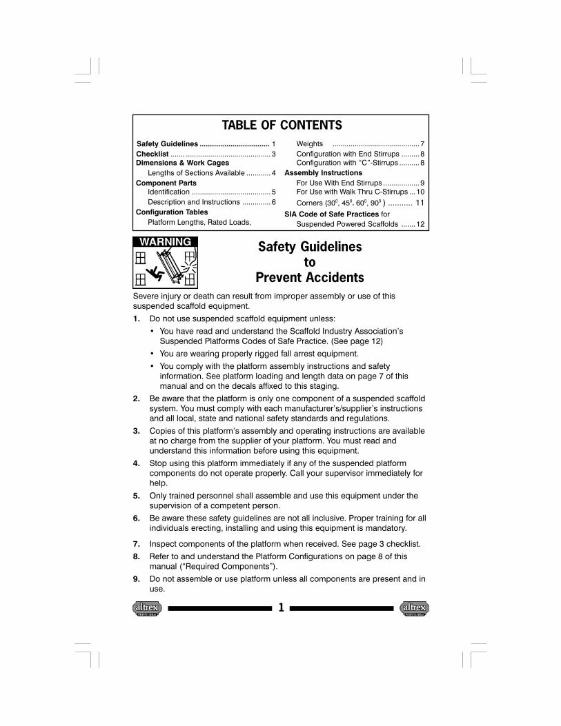
Safety Guidelinesto
Prevent AccidentsSevere injury or death can result from improper assembly or use of thissuspended scaffold equipment.
1. Do not use suspended scaffold equipment unless:
• You have read and understand the Scaffold Industry Association’sSuspended Platforms Codes of Safe Practice. (See page 12)
• You are wearing properly rigged fall arrest equipment.
• You comply with the platform assembly instructions and safetyinformation. See platform loading and length data on page 7 of thismanual and on the decals affixed to this staging.
2. Be aware that the platform is only one component of a suspended scaffoldsystem. You must comply with each manufacturer’s/supplier’s instructionsand all local, state and national safety standards and regulations.
3. Copies of this platform’s assembly and operating instructions are availableat no charge from the supplier of your platform. You must read andunderstand this information before using this equipment.
4. Stop using this platform immediately if any of the suspended platformcomponents do not operate properly. Call your supervisor immediately forhelp.
5. Only trained personnel shall assemble and use this equipment under thesupervision of a competent person.
6. Be aware these safety guidelines are not all inclusive. Proper training for allindividuals erecting, installing and using this equipment is mandatory.
7. Inspect components of the platform when received. See page 3 checklist.
8. Refer to and understand the Platform Configurations on page 8 of thismanual (“Required Components”).
9. Do not assemble or use platform unless all components are present and inuse.
Safety Guidelines .................................. 1 Checklist ....... .......................................... 3 Dimensions & Work Cages
Lengths of Sections Available ............ 4 Component Parts
Identification ....................................... 5Description and Instructions .............. 6
Configuration TablesPlatform Lengths, Rated Loads,
Weights ........................................... 7Configuration with End Stirrups ......... 8Configuration with “C”-Stirrups .......... 8
Assembly InstructionsFor Use With End Stirrups .................. 9For Use with Walk Thru C-Stirrups ... 10
Corners (300, 450, 600, 900 ) ........... 11 SIA Code of Safe Practices for
Suspended Powered Scaffolds ....... 12
TABLE OF CONTENTS

2
10. This platform has been designed, engineered, manufactured and tested toexacting standards - do not modify this platform in any way!
11. DANGER! metal conducts electricity. Never use metal platforms nearelectrical current. Contact the local electrical utility for recommendations.
12. Do not apply impact loads to platform (dropping anything on the deck ofthe platform).
13. If the platform is exposed to excessive heat (as in the case of a fire),remove platform from service (structural strength may be compromised).
14. Do not weld anything to the component parts of this platform (structuralstrength may be compromised).
15. Do not subject his Platform to acids (such as muriac or hydrochloric) orother corrosive substances that can seriously effect the strength of alumi-num. Should such substances come in contact with this platform, theymust be immediately cleaned from the equipment by flushing with waterand neutralizing as quickly as possible. Remove all platform sectionssuspected or subjected to corrosive attack from service.
16. Keep platform deck free from debris (especially oil or grease, which cancause a slipping hazard).
17. Keep the platform level at all times.
18. Do not overload or extend Platform’s total length or loading beyond U.L.classification (see information contained in chart of Page 7 of this manual).Be sure to evenly distribute weight (loading) on platform and to roof rigaccordingly (adequate counterweights and tie backs).
19. Replace broken or damaged platform components as necessary. Checkstirrups, connections and platform condition prior to each use.
20. Check that all quickpins are in place and retained with locking (lynch) pinsprior to each use.
21. When using cantilevered sections, refer to chart on Page 7 of this manualfor correct configurations to be used. Note that cantilevered sections mustbalance (be equal in length).
22. Be sure the hoists being used fit the platform properly and that their stirrupbar aligns with the platform mounting brackets/plates. Use only hardwarefurnished by the hoist manufacturer, (grade 5 hardware or better).
23. Be sure wire rope is properly routed through pulleys and inlet guides at topof walk thru type stirrups.
24. Additional copies of warning labels are available should the originallabeling become damaged, obscured or removed. Contact your Up-Stageplatform supplier.
25. DO NOT USE platform when the wind speed exceeds 25 mph.
Safety Guidelines (continued)

3
Checklists
If you check off any boxes under “NO”, do not use this platform until theproblem is corrected and immediately contact your supervisor or supplier.
Inspection checklist prior to installation
YES NO
I have read and understand this operating manual.
All labels (including load ratings and configurations) are in place andclearly legible.
All components are present per the configuration tables on page 8.
The spring-loaded buttons on the guardrails and guardrail posts arein place and operate properly. A Quickpin may be used in lieu of aspring-loaded button.
All components are in good working order and do not have any of thefollowing defects:
• Cracked or torn welds.
• Cracked or deformed parts that could weaken the platform.
• Deformations that do not allow normal installation.
• Deformations or cracked connection holes.
Inspection checklist after installationPerform this inspection after installation AND prior to each workshift.
YES NO
The load rating as listed in the table on page 7 is not exceeded.
Each Side Frame is connected to the U-frames with 4 Quickpins.
Each Quickpin is secured with a locking clip (lynch pin).
The Decks are properly locked in by the Deck Spring Clips.
The Roller Bumpers are properly fastened.
Each End Stirrup is secured with an axle rod or 2 Quickpins.
The toeboard brackets on the Walk Thru Stirrups are properly fastened.
The stirrups are in line with the rigging points above.
Operating instructions of hoists and platform are kept on the platform.
The platform is clear of any snow, ice, debris or other material.
All labels are in place and clearly legible.
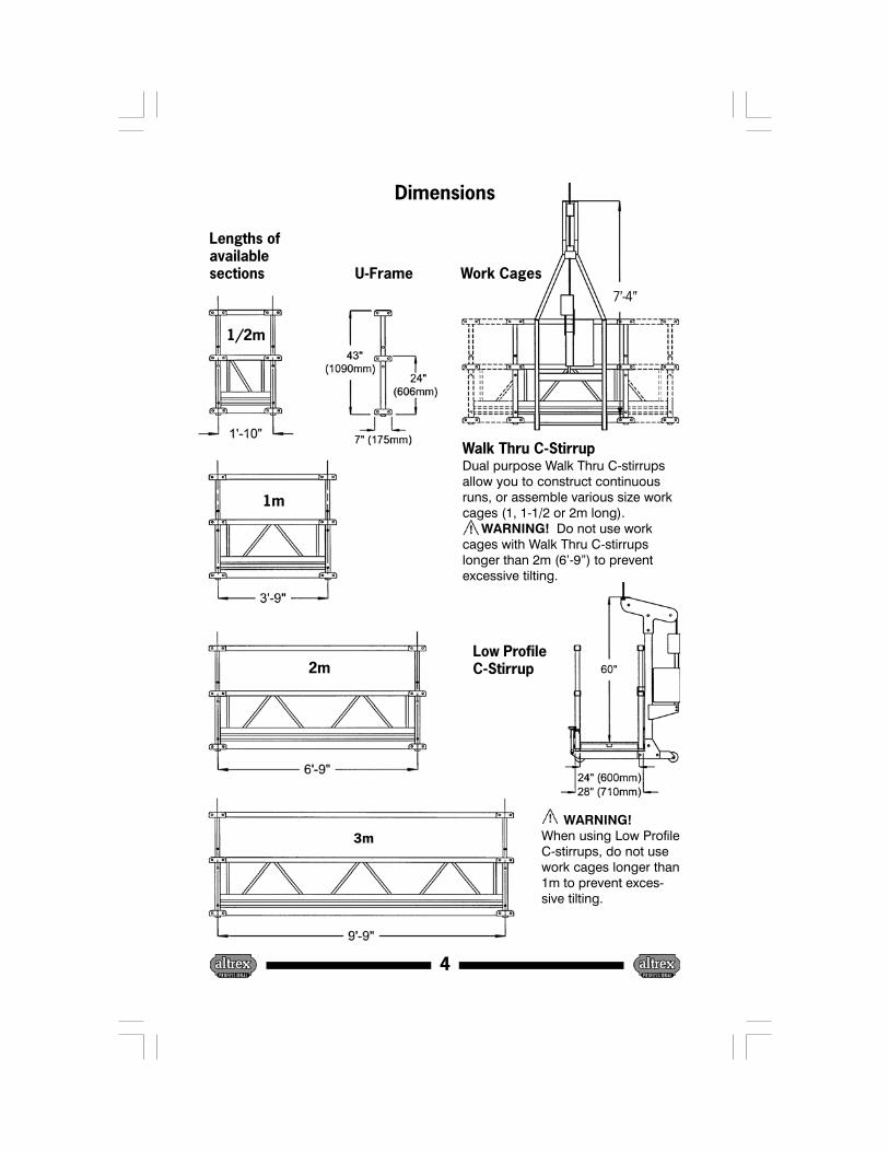
WARNING!When using Low ProfileC-stirrups, do not usework cages longer than1m to prevent exces-sive tilting.
Dual purpose Walk Thru C-stirrupsallow you to construct continuousruns, or assemble various size workcages (1, 1-1/2 or 2m long). WARNING! Do not use workcages with Walk Thru C-stirrupslonger than 2m (6’-9”) to preventexcessive tilting.
Dimensions
U-Frame
4
Lengths ofavailablesections
2m
3m
1m
7’-4”
1/2m
Work Cages
Walk Thru C-Stirrup
Low ProfileC-Stirrup
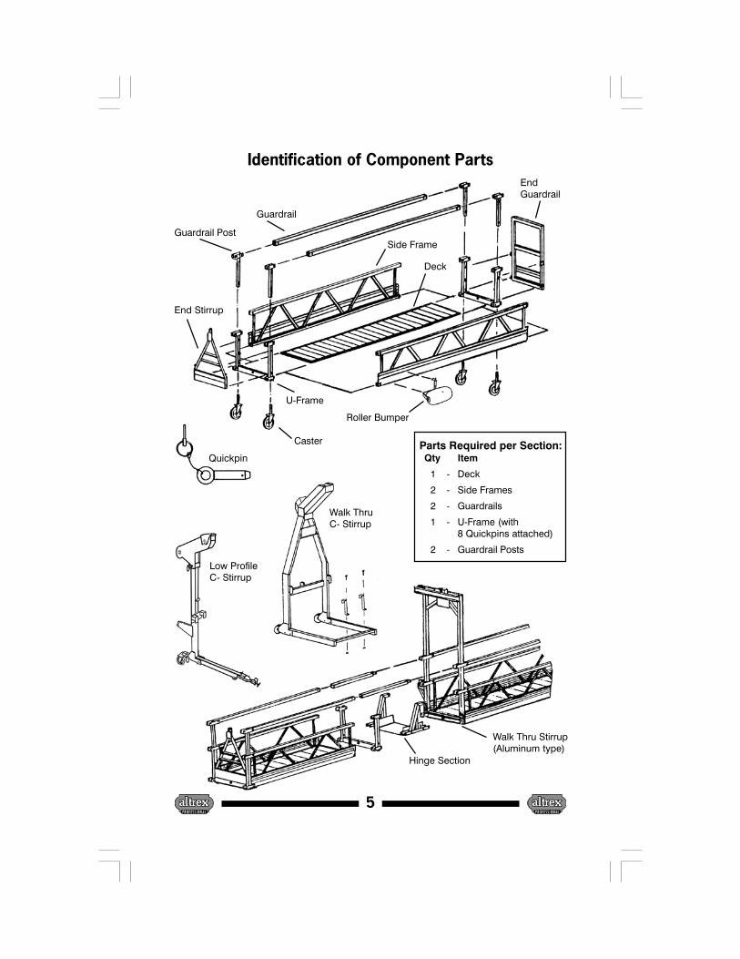
Identification of Component Parts
Side Frame
Deck
U-Frame
End Stirrup
Guardrail Post
Guardrail
Caster
EndGuardrail
Roller Bumper
5
Walk Thru Stirrup(Aluminum type)
Parts Required per Section:Qty Item
1 - Deck
2 - Side Frames
2 - Guardrails
1 - U-Frame (with8 Quickpins attached)
2 - Guardrail Posts
Walk ThruC- Stirrup
Hinge Section
Quickpin
Low ProfileC- Stirrup

1. Side Frame: The structural side panel that incorporates the toe board and mid rail.2. Aluminum Deck: Dual sided decks can be flipped over in order to utilize
both working surfaces. The panels in the deck are separated to reduce theeffects of wind on the platform and so water can properly drain.
3. U-Frame: Connects the side frames by using quickpins. The followingcomponents are mounted to the U-frame: guardrail posts, casters,end stirrup or end guardrail.
4. End Stirrup: Fastened to the U-frame with a stirrup rod and retaining lynchpin. This arrangement allows the end stirrup to fully pivot from the horizontalposition when the hoists are under load. The “^” saddle on each side of theU-frame, mates with the “^” saddle on the end stirrup A-frame. The saddlesallow the end stirrup, with hoist attached, to be stabilized in an uprightposition when there is no tension or load on the hoists.
5. Guardrail Post: Guardrail posts are mounted in the U-frame (two posts perU-Frame). They are fastened to the proper 42-inch height by means of aspring-loaded compression button.
6. Guardrail: The guardrail is mounted in the guardrail post by means of springloaded compression buttons. Guardrails are required on both sidesof each platform section unless special stabilization procedures are in effect(for front guard rail removal only).
7. Caster: Allows platform to be easily moved at ground level. Normally, aplatform requires 4 casters, but longer length platforms may require morecasters in the center to facilitate movement. Casters are mounted to agalvanized steel stem that are inserted into the bottom of the U-frame andfastened with an end stirrup axle rod or quick pins (if end guard rails arebeing used).
8. Quickpin: Quickpins secure the side frames to the U-frames. Quickpins aresecured in place by means of a lynch pin. There are four sets of quick pins(8 pins total) attached to each U-frame by a steel wire rope lanyard. Use onlyfactory supplied quickpin sets.
9. End Guardrail: Mounts inside the U-frame of a section by using quickpins.End guardrails are necessary when walk-thru stirrups are used.
10. Roller Bumper: Roller bumper brackets mount to the toeboard via a wingnut or T-handle securing system. Normally, 2 roller bumpers are used oneach platform; however, corner platforms may require additional rollerbumpers. At times replacement rollers should be installed on the rollerbumper brackets due to wear and job conditions.
11. Walk-Thru and Low Profile C-Stirrup: Can be mounted at any location on aplatform section. It is attached to the back midrail of a platform section via anattachment bracket. Also a front retaining bracket locks to the front toeboard.End guard rails must be used in conjunction with this type of stirrup.
12. Walk-Thru Aluminum Stirrup: Mounted in place of a U-frame. Normally usedin conjunction with a hinge section. Federal Regulations require use of ahinge section whenever there are more than two hoists (stirrups) mountedon a straight platform and in certain corner platform configurations. Hingesections relieve torque stresses that could otherwise cause a platform to fail.End guard rails must be employed when using this type of stirrup.
Description of Component Parts & Instructions
6

TOTAL LENGTH OF EA MAX. SPAN PLATFORM RATED TOTALLENGTH CANTILEVER Dist. Betw. Hoists CONFIGURATION WORKING LOAD PLATFORM WT
Ft. Meter Ft. Meter Ft. Meter In Meters Lbs. Kg. Lbs. Kg.
6 2 None 6 2 2 2000 907 160 73
10 3 None 10 3 3 2000 907 200 91
13 4 None 13 4 2-2 2000 907 271 123
16 5 None 16 5 3-2 2000 907 310 141
20 6 None 20 6 3-3 2000 907 348 158
23 7 None 23 7 2-3-2 1500 680 420 191
26 8 None 26 8 3-2-3 1500 680 458 208
30 9 None 30 9 3-3-3 1000 454 494 233
33 10 None 33 10 3-2-2-3 1000 454 568 258
36 11 None 36 11 3-3-3-2 1000 454 607 276
40 12 None 40 12 3-3-3-3 1000 454 645 293
43 13 None 43 13 3-3-2-2-3 750 340 717 326
46 14 None 46 14 3-3-2-3-3 750 340 755 343
49 15 None 49 15 3-3-3-3-3 750 340 830 361
30 9 3 1 23 7 1 2-3-2 1 750 340 847 385
33 10 3 1 26 8 1 3-2-3 1 1000 454 884 402
36 11 3 1 30 9 1 3-3-3 1 1000 454 924 420
40 12 3 1 33 10 1 3-2-2-3 1 1000 454 994 452
43 13 3 1 36 11 1 3-3-3-2 1 1000 454 1034 470
46 14 3 1 40 12 1 3-3-3-3 1 1000 454 1071 487
49 15 3 1 43 13 1 3-3-2-2-3 1 750 340 1144 520
52 16 3 1 46 14 1 3-3-2-3-3 1 750 340 1181 537
56 17 3 1 49 15 1 3-3-3-3-3 1 750 340 1221 555
46 14 6 2 33 10 2 3-2-2-3 2 750 340 1056 480
49 15 6 2 36 11 2 3-3-3-2 2 750 340 1096 498
52 16 6 2 40 12 2 3-3-3-3 2 750 340 1133 515
56 17 6 2 43 13 2 3-3-2-2-3 2 750 340 1206 548
59 18 6 2 46 14 2 3-3-2-3-3 2 750 340 1234 565
62 19 6 2 49 15 2 3-3-3-3-3 2 750 340 1283 583
CantileverPlatform
Maximum Span Between Supporting Stirrups CantileverPlatform
Explanation of Cantilevered SectionsWireRope
WireRope
Example of Platform Build(Refer to Configuration Column)
SUSPENSION POINT
1 3 - 3 - 3 1
CANTILEVERED SECTIONS
SECTION BETWEEN HOISTS
PLATFORM LENGTHS • CONFIGURATIONS • RATED LOADS • TOTAL WEIGHT
NOTES:• All Platforms must be assembled as detailed in the Platform Configuration Column (above). This is the
manner in which the Platforms were tested and classified by U.L.• This chart takes into consideration that 2 powered scaffold hoists will be used.• WARNING! Any platform configuration not listed on this chart must be approved by the
manufacturer prior to use. Failure to comply with this may result in death or serious injury.• Total platform weight does not include weight of hoist, bumpers, casters, material or workers.• WARNING! Rated Working Load must be evenly distributed on Platform.• The above figures allow for “C”- Type Stirrups not exceeding 140 lbs.
7

3’9” 6’-9” 9’-9” 13’-6” 16’-6” 19’-6” 23’-3” 26’-3” 29’-3” 33’-0” 36’-0” 39’-0” 42’-9” 45’-9” 48’-9”Item Part No. 1m 2m 3m 4m 5m 6m 7m 8m 9m 10m 11m 12m 13m 14m 15m
1M Side Frame 421061 2
1M Guardrail 422011 2
1M Deck 422901 1
2M Side Frame 421062 2 4 2 4 2 4 2 4 2
2M Guardrail 422012 2 4 2 4 2 4 2 4 2
2M Deck 422902 1 2 1 2 1 2 1 2 1
3M Side Frame 421063 2 2 4 2 4 6 4 6 8 6 8 10
3M Guardrail 422013 2 2 4 2 4 6 4 6 8 6 8 10
3M Deck 422903 1 1 2 1 2 3 2 3 4 3 4 5
U-Frame 421508 2 2 2 3 3 3 4 4 4 5 5 5 6 6 6
Guardrail Post 421520 4 4 4 6 6 6 8 8 8 10 10 10 12 12 12
End Stirrup 934102 2 2 2 2 2 2 2 2 2 2 2 2 2 2 2
8" Caster 934109 4 4 4 4 4 4 4 4 4 4 4 4 4 4 4
Roller Bumper 934113 2 2 2 2 2 2 2 2 2 2 2 2 2 2 2
Configuration Table with Walk Thru StirrupsRequired Components for Platform Length
9’-9” 13’-6” 16’-6” 19’-6” 23’-3” 26’-3” 29’-3” 33’-0” 36’-0” 39’-0” 42’-9” 45’-9” 48’-9” 52’3"ft 56’3"ft 59’3"ft 62’3"ftItem 3m 4m 5m 6m 7m 8m 9m l0m 11m 12m 13m 14m 15m 16m 17m 18m 19m
1M Side Frame 421061
1M Guardrail 422011
1M Deck 422901
2M Side Frame 421062 4 2 4 2 4 2 4 2 4 8 6 4
2M Guardrail 422012 4 2 4 2 4 2 4 2 4 8 6 4
2M Deck 422902 2 1 2 1 2 1 2 1 2 4 3 2
3M Side Frame 421063 2 2 4 2 4 6 4 6 8 6 8 10 8 6 8 10
3M Guardrail 422013 2 2 4 2 4 6 4 6 8 6 8 10 8 6 8 10
3M Deck 422903 1 1 2 1 2 3 2 3 4 3 4 5 4 3 4 5
U-Frame 421508 2 3 3 3 4 4 4 5 5 5 6 6 6 7 8 8 8
Guardrail Post 421520 4 6 6 6 8 8 8 10 10 10 12 12 12 14 16 16 16
End Guardrail 423072 2 2 2 2 2 2 2 2 2 2 2 2 2 2 2 2 2
C-Stirrup 934111 2 2 2 2 2 2 2 2 2 2 2 2 2 2 2 2 2
8" Caster 934109 4 4 4 4 4 4 4 4 4 4 4 4 4 4 4 4 4
Roller Bumper 934113 2 2 2 2 2 2 2 2 2 2 2 2 2 2 2 2 2
Configuration Table with End StirrupsRequired Components for Platform Length
PartNo
8
WARNING: Any platform configuration not listed on this chart must beapproved by the manufacturer prior to use. Failure to comply mayresult in death or serious injury.
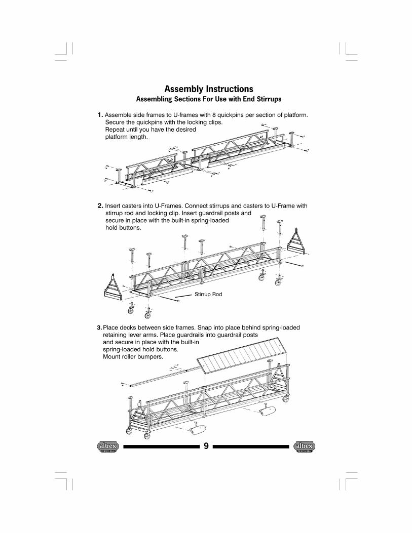
Assembly InstructionsAssembling Sections For Use with End Stirrups
9
1. Assemble side frames to U-frames with 8 quickpins per section of platform. Secure the quickpins with the locking clips. Repeat until you have the desired platform length.
2. Insert casters into U-Frames. Connect stirrups and casters to U-Frame with stirrup rod and locking clip. Insert guardrail posts and secure in place with the built-in spring-loaded hold buttons.
3. Place decks between side frames. Snap into place behind spring-loadedretaining lever arms. Place guardrails into guardrail postsand secure in place with the built-inspring-loaded hold buttons.Mount roller bumpers.
Stirrup Rod
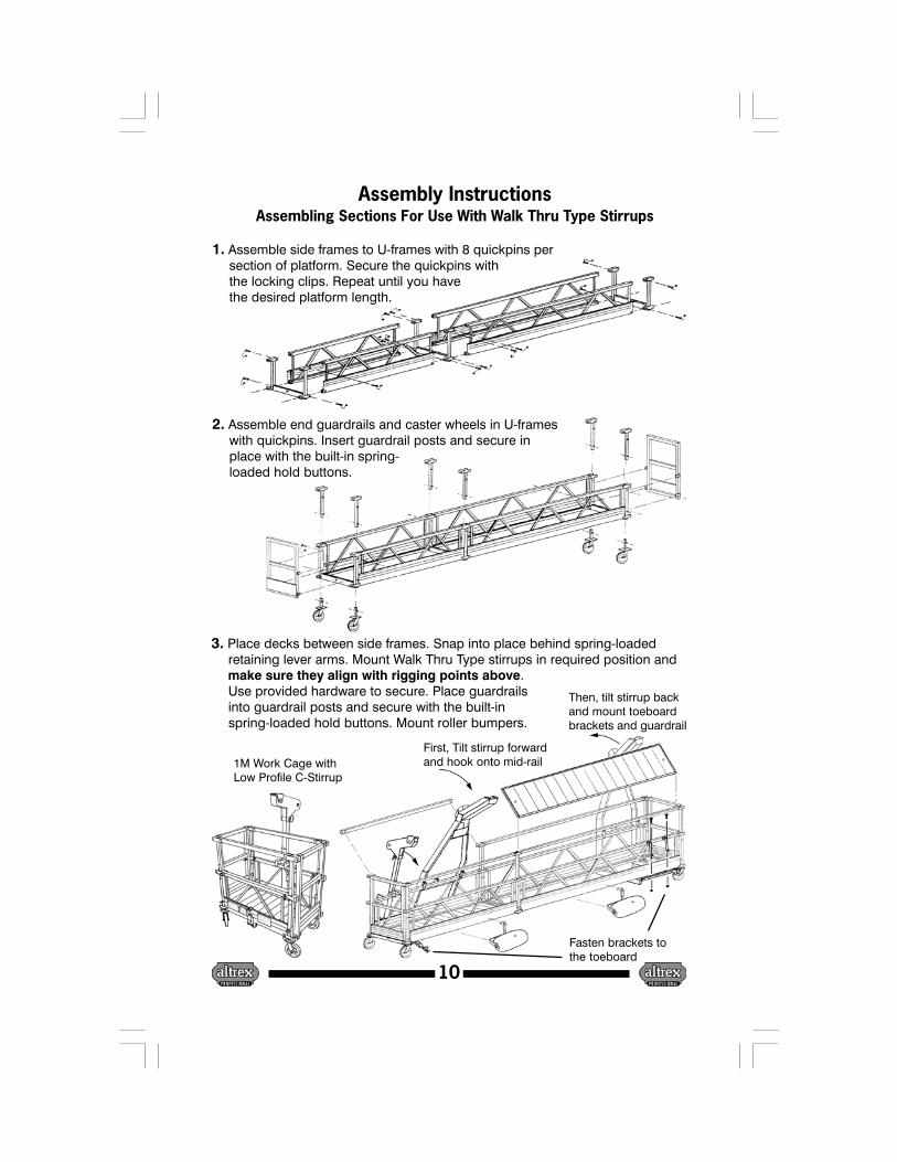
Assembly InstructionsAssembling Sections For Use With Walk Thru Type Stirrups
10
2. Assemble end guardrails and caster wheels in U-frames with quickpins. Insert guardrail posts and secure in place with the built-in spring- loaded hold buttons.
1. Assemble side frames to U-frames with 8 quickpins per section of platform. Secure the quickpins with the locking clips. Repeat until you have the desired platform length.
3. Place decks between side frames. Snap into place behind spring-loaded retaining lever arms. Mount Walk Thru Type stirrups in required position and make sure they align with rigging points above. Use provided hardware to secure. Place guardrails into guardrail posts and secure with the built-in spring-loaded hold buttons. Mount roller bumpers.
First, Tilt stirrup forwardand hook onto mid-rail
Then, tilt stirrup backand mount toeboardbrackets and guardrail
Fasten brackets tothe toeboard
1M Work Cage withLow Profile C-Stirrup

Assembly Instructions - Corners
11
Assembly drawings for fixed corners (300, 450, 600, 900). Note dimensions.
Component Description1= 900 Weldment Assembly2= Deck3= Front Side Frame4= Rear Side Frame5= Front Guardrail5= Rear Guardrail7= Guardrail Post
600 Corner
450 Corner
300 Corner
900 Corner
It shall be the responsibility of all users to readand comply with the following common senseguidelines which are designed to promote safetyin the erecting, dismantling and use of Sus-pended Powered Scaffolds. These guidelines donot purport to be all-inclusive nor to supplant orreplace other additional safety and precautionarymeasures to cover usual or unusual conditions. Ifthese guidelines in any way conflict with any state,local, provincial, federal or other governmentstatute or regulation, said statute or regulationshall supersede these guidelines and it shall bethe responsibility of each user to complytherewith.
II. GENERAL GUIDELINES
A. POST THESE SAFETY GUIDELINES in aconspicuous place and be sure that all personswho erect, use, locate, or dismantle sus-pended scaffold systems are fully aware ofthem and also use them in tool box safetymeetings
B. FOLLOW ALL EQUIPMENT MANUFACTUR-ERS’ RECOMMENDATIONS as well as allstate, local and federal codes, ordinances andregulations relating to suspended poweredscaffolding.
C. SURVEY THE JOBSITE. A survey shall bemade of the jobsite by a competent person forhazards such as exposed electrical wires,obstructions that could overload or tip thesuspended powered scaffold when it is raisedor lowered, unguarded roof edges oropenings, inadequate or missing tiebacks.Those conditions should be corrected beforeinstalling or using suspended powered scaffoldsystems.
D. INSPECT ALL EQUIPMENT BEFORE EACHUSE. Never use any equipment that isdamaged or defective in any way. Mark it or tagit as damaged or defective equipment andremove it from the jobsite.
E. ERECT AND DISMANTLE SUSPENDEDPOWERED SCAFFOLD EQUIPMENT inaccordance with design and/or manufacturer’srecommendations.
F. DO NOT ERECT, DISMANTLE, OR ALTERSUSPENDED POWERED SCAFFOLDSYSTEMS unless under the supervision of acompetent person.
G. DO NOT ABUSE OR MISUSE SUSPENDEDPOWERED SCAFFOLD EQUIPMENT. Neveroverload platforms or hoists.
H. ERECTED SUSPENDED POWEREDSCAFFOLDS SHOULD BE CONTINUOUSLYINSPECTED by the user to ensure that theyare maintained in a safe condition. Report anyunsafe condition to your supervisor.
I. NEVER TAKE CHANCES! IF IN DOUBTREGARDING THE SAFETY OR USE OFSUSPENDED SCAFFOLDS, CONSULT YOURSCAFFOLD SUPPLIER.
J. NEVER USE SUSPENDED SCAFFOLDEQUIPMENT FOR PURPOSES OR IN WAYSFOR WHICH IT WAS NOT INTENDED.
K. CARE SHOULD BE TAKEN WHEN OPERAT-ING AND STORING EQUIPMENT DURINGWINDY CONDITIONS.
L. SUSPENDED POWERED SCAFFOLDSYSTEMS should be installed and used inaccordance with the manufacturer’s recom-mended procedures. Do not alter componentsin the field.
M. SUSPENDED POWERED PLATFORMSMUST NEVER BE OPERATED NEAR LIVEPOWER LINES unless proper precautions aretaken. Consult the power service company foradvice.
N. ALWAYS ATTACH FALL ARREST EQUIP-MENT when working on suspended poweredscaffolds.’
O. DO NOT WORK ON OR INSTALL SUS-PENDED POWERED SCAFFOLDS if yourphysical condition is such that you feel dizzy orunsteady in any way.
P. DO NOT WORK ON SUSPENDED POWEREDSCAFFOLDS when under the influence ofalcohol or illegal drugs.
II. GUIDELINES FOR ERECTION AND USE OFSUSPENDED SCAFFOLD SYSTEMS
A. RIGGING:
I. WEAR FALL PREVENTION EQUIPMENTwhen rigging on exposed roofs or floors.
2. ROOF HOOKS, PARAPET CLAMPS,OUTRIGGER BEAMS, OR OTHERSUPPORTING DEVICES must be capableof supporting the hoist machine rated loadwith a safety factor of 4.
3. VERIFY THAT THE BUILDING ORSTRUCTURE WILL SUPPORT thesuspended loads with a factor of safety of 4.
Code of Safe Practices for Suspended Powered Scaffolds
12
4. ALL OVERHEAD RIGGING must besecured from movement in any direction.
5. COUNTERWEIGHTS USED WITHOUTRIGGER BEAMS must be of a non-flowable material and must be secured tothe beam to prevent accidentaldisplacement.
6. OUTRIGGER BEAMS THAT DO NOT USECOUNTERWEIGHTS must be installed andsecured on the roof structure with devicesspecifically designed for that purpose. Directconnections shall be evaluated by acompetent person.
7. TIE BACK ALL TRANSPORTABLERIGGING DEVICES. Tiebacks shall beequivalent in strength to suspension ropes.
8. INSTALL TIEBACKS AT RIGHT ANGLESTO THE FACE OF THE BUILDING andsecure, without slack, to a structurally soundportion of the structure, capable ofsupporting the hoisting machine rated loadwith a safety factor of 4. IN THE EVENTTIEBACKS CANNOT BE INSTALLED ATRIGHT ANGLES, two tiebacks at opposingangles must be used to prevent movement.
9. RIG AND USE HOISTING MACHINESDIRECTLY UNDER THEIR SUSPENSIONPOINTS.
B. WIRE ROPE AND HARDWARE:
1. USE ONLY WIRE ROPE ANDATTACHMENTS as specified by thehoisting machine manufacturer.
2. ASSURE THAT WIRE ROPE IS LONGENOUGH to reach to the lowest possiblelanding.
3. CLEAN AND LUBRICATE WIRE ROPEin accordance with the wire ropemanufacturer’s instructions.
4. HANDLE WIRE ROPE WITH CARE.
5. COIL AND UNCOIL WIRE ROPE inaccordance with the wire ropemanufacturer’s instructions in order to avoidkinks or damage.
6. TIGHTEN WIRE ROPE CLAMPS inaccordance with the clamp manufacturer’sinstructions.
7. DO NOT USE WIRE ROPE THAT ISKINKED, BIRDCAGED, CORRODED,UNDERSIZED, OR DAMAGED IN ANYWAY. Do not expose wire rope to fire, undueheat, corrosive atmosphere, electricity,chemicals, or damage by tool handling.
8. USE THIMBLES AND SHACKLES ATALL WIRE ROPE SUSPENSIONTERMINATIONS.
9. USE J-TYPE CLAMPS OR SWAGEDFITTINGS. Do not use U-bolts. Retighten J-Clamps under load and retighten daily.
10. WIRE ROPES USED WITH TRACTIONHOISTS MUST HAVE PREPARED ENDS.Follow manufacturer’s recommendations.
C. POWER SUPPLY
1. GROUND ALL ELECTRICAL POWERSOURCES AND POWER CORDCONNECTIONS and protect them withcircuit breakers.
2. USE POWER CORDS OF THE PROPERWIRE SIZE THAT ARE LONG ENOUGH forthe job.
3. POWER CORD CONNECTIONS MUST BERESTRAINED to prevent their separation.
4. USE STRAIN RELIEF DEVICES TOATTACH POWER CORDS TO THESUSPENDED SCAFFOLD to prevent themfrom falling.
5. PROTECT POWER CORDS AT SHARPEDGES.
6. USE GFI WITH POWER TOOLS.
D. FALL ARREST EQUIPMENT
I. EACH PERSON ON A SUSPENDEDPOWERED SCAFFOLD must be attached toa separate fall arrest system unless theinstallation was specifically designed not torequire one.
2. EACH LIFELINE MUST BE FASTENED to aseparate anchorage capable of holding aminimum of 5000 pounds.
3. DO NOT WRAP LIFELINES AROUNDSTRUCTURAL MEMBERS unless lifelinesare protected and a suitable anchorageconnection is used.
Code of Safe Practices for Suspended Powered Scaffolds(continued)
13

4. PROTECT LIFELINES AT SHARPCORNERS to prevent chafing.
5. RIG FALL ARREST SYSTEMS to preventfree fall in excess of six feet.
6. SUSPEND LIFELINES FREELY withoutcontact with structural members or buildingfacade.
7. USE LIFELINES OF SIZE ANDCONSTRUCTION that are compatible withthe rope grab used.
8. ASSURE A PROPERLY ATTACHED ROPEGRAB IS INSTALLED ON EACH LIFELINE. Install in accordance with themanufacturer’s recommendations.
9. KEEP FALL ARREST DEVICEPOSITIONED ABOVE YOUR HEADLEVEL.
10. USE ONLY FULL BODY HARNESSES ofthe proper size and that are tightlyfastened.
11. ASSURE FULL BODY HARNESS HASLANYARD attachment with D-ring at thecenter of your back.
12. CONSULT FALL PROTECTIONSUPPLIER FOR INSPECTIONPROCEDURE. INSPECT FALLPROTECTION ANCHORAGE /EQUIPMENT BEFORE EACH USE.
13 .WHEN A SECONDARY WIRE ROPESYSTEM IS USED, a horizontal lifelinesecured to two or more structural membersof the scaffold may be used in lieu ofvertical lifelines.
E. DURING USE:
I. USE ALL EQUIPMENT AND ALL DEVICESin accordance with the manufacturer’sinstructions.
2. DO NOT OVERLOAD, MODIFY, ORSUBSTITUTE EQUIPMENT
3. BEFORE COMMENCING WORKOPERATIONS preload wire rope andequipment with the maximum working load,then retighten wire rope rigging clamps andrecheck rigging to manufacturer’srecommendations.
Code of Safe Practices for Suspended Powered Scaffolds(continued)
4. INSPECT ALL RIGGING EQUIPMENTAND SUSPENDED POWER SCAFFOLDSYSTEMS DAILY.
5. INSPECT WIRE ROPE DURING EACHASCENT OR DESCENT FOR DAMAGE.
6. USE CARE TO PREVENT DAMAGE TOEQUIPMENT by corrosive or otherdamaging substances.
7. CLEAN AND SERVICE EQUIPMENTREGULARLY.
8. ALWAYS MAINTAIN AT LEAST ( 4) FOURWRAPS OF WIRE ROPE ON DRUM TYPEHOISTS.
9. DO NOT JOIN PLATFORMS unless theinstallation was designed for that purpose.
10. ONLY MOVE SUSPENDED SCAFFOLDSHORIZONTALLY WHEN NOT OCCUPIED.
11. WHEN RIGGING FOR ANOTHER DROPassure sufficient wire rope is availablebefore moving the suspended scaffoldsystem horizontally.
12. WHEN WELDING FROM SUSPENDEDPOWERED SCAFFOLDS:
a. Assure platform is grounded to structure.
b. Insulate wire rope above and below theplatform.
c. Insulate wire rope at suspension pointand assure wire rope does not contactstructure along its entire length.
d. Prevent the bitter end from touching theground.
14
UP-STAGE OPS MANUAL 984101
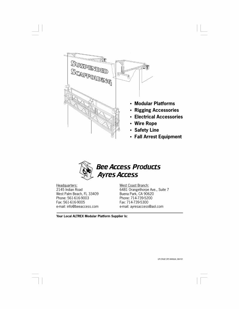
Your Local ALTREX Modular Platform Supplier Is:
• Modular Platforms• Rigging Accessories• Electrical Accessories• Wire Rope• Safety Line• Fall Arrest Equipment
West Coast Branch:6481 Orangethorpe Ave., Suite 7Buena Park, CA 90620Phone: 714-739-5200Fax: 714-739-5300e-mail: [email protected]
Headquarters:2145 Indian RoadWest Palm Beach, FL 33409Phone: 561-616-9003Fax: 561-616-9005e-mail: [email protected]
Bee Access Products Ayres Access