assembly & installation instructions revision 1
TRANSCRIPT

ASSEMBLY & INSTALLATION INSTRUCTIONS REVISION 1
www.sortimo.knapheide.com

2
ASSEMBLY & INSTALLATION INSTRUCTIONS
MOUNTING ITEMS
A
B
L1
L2
C
D
PN 1000002427
PN 1000002435
PN 71005206
PN 6000002059
PN 1000002442
PN 1000002441

3
ASSEMBLY & INSTALLATION INSTRUCTIONS
EM6
FM6
G
HI
TOOLS
PH2
4
HARDWARE* Some shelving staxx may contain extra hardware
PN 6000002069
PN 6000001148
Part supplied with blue frame grips
PN 71003884
PN 71003987PN 71003988
J
PN 71009864

4
ASSEMBLY & INSTALLATION INSTRUCTIONS
Exxpand Installation summary:
1. Exxpand block assembly Reference steps 1-7
2. Place the Exxpand block in the vehicle and place it in the best position for EcoFix bracket mounting Refer to step 1 for specific guidance on horizontal braces
3. Bend EcoFix mounting brackets for the side wall fastening Refer to steps 8-10
4. Mark the floor and wall mounting positions Refer to step 10 for floor mounting
5. Remove Exxpand block from vehicle
6. Drill all marks on vehicle floor and side wall mounting positions
7. Insert rivnuts in vehicle floor & wall Refer to step 10 for floor
8. Place the Exxpand block back in the vehicle
9. Align Exxpand block according to the floor and wall mounting points.
10. First, install floor mounting hardware, second install all hardware for side-wall mounting Refer to steps 10-11
Note: Van specific instructions located on pages 23-24. !

5
ASSEMBLY & INSTALLATION INSTRUCTIONS
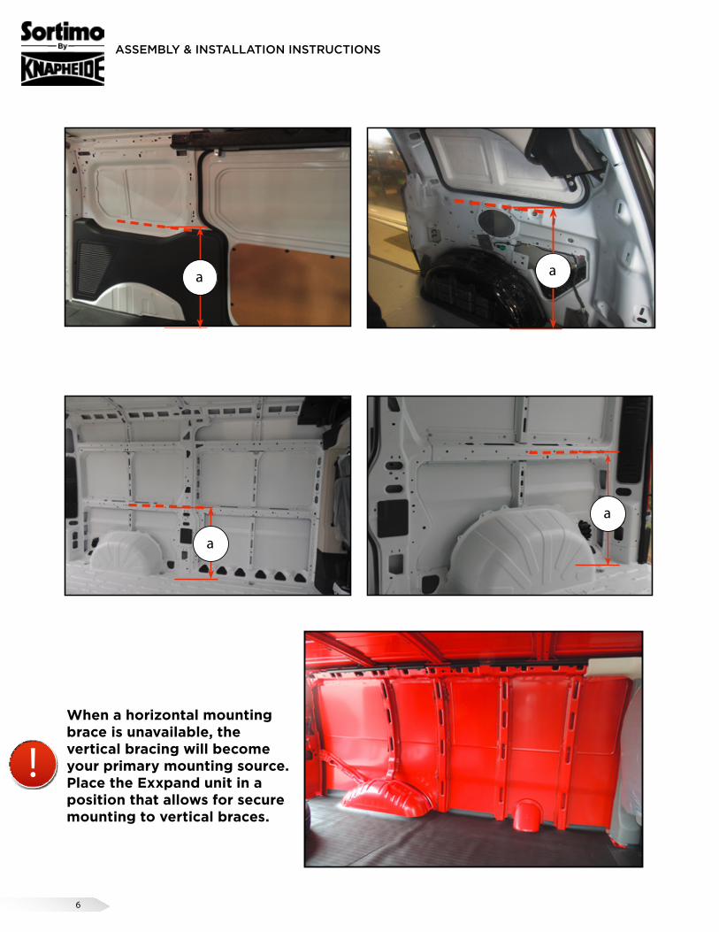
"A" Dimension
The measurement from vehicle floor to a horizontal mounting brace on the vehicle sidewall.
Note: Not all vehicles will have a horizontal mounting option.
1
a
a
6
ASSEMBLY & INSTALLATION INSTRUCTIONS
When a horizontal mounting brace is unavailable, the vertical bracing will become your primary mounting source. Place the Exxpand unit in a position that allows for secure mounting to vertical braces.
a
!
a
a
a

7
ASSEMBLY & INSTALLATION INSTRUCTIONS
2x 4
"A" Dimension ShelfOnly attach the shelf to the pultrusion with the side mounting bolts at this time. Leave the rear holes open for mounting purposes (reference page 5).
Top ShelfTop shelf must be mounted to allow for a minimum of two open holes above for clearance of Sortimo top piece. (See step 6).
Bottom ShelfBottom shelf needs to be placed in a way so that it will clear the wheel well.
F 10
4
E
2
Assemble all other shelves as pictured.
PN 6000002069 PN 71003884

8
ASSEMBLY & INSTALLATION INSTRUCTIONS
Floor angles should face the front of the vehicle per crash test data depicted in illustration below.
ÆÅA ÅA
A
2x A
8x F2x A
2x 4
3
!
10
4
8x E
A
PN 1000002427 PN 6000002069 PN 71003884

9
ASSEMBLY & INSTALLATION INSTRUCTIONS
In certain vehicles this will not be possible due to mounting obstructions. When this happens you must use the supplied backing plates in conjunction with the mounting foot that is facing the incorrect way to help strengthen the side wall pultrusion.
The above photo simulates an obstruction not allowing the floor angle to be placed facing forward in its correct position. This shows the placement of the backing plates to help strengthen sidewall pultrusion.
Vehicle Front
!

10
ASSEMBLY & INSTALLATION INSTRUCTIONS
Primary Method for ease of installation around wheel well.
Diagonal brace must always start at the top of the stack from the front of the vehicle descending rearward on the Exxpand unit.
2x B
!
Æ
Æ
Æ
4x F 10
4
4x E
4
PN 1000002435
PN 6000002069 PN 71003884

11
ASSEMBLY & INSTALLATION INSTRUCTIONS
N M BF E� �
8x F 10
4
8x E
5PN 6000002069 PN 71003884
N
MB
N
B
M
J
J
PN 6000001148
N M BF E� �
12
ASSEMBLY & INSTALLATION INSTRUCTIONS
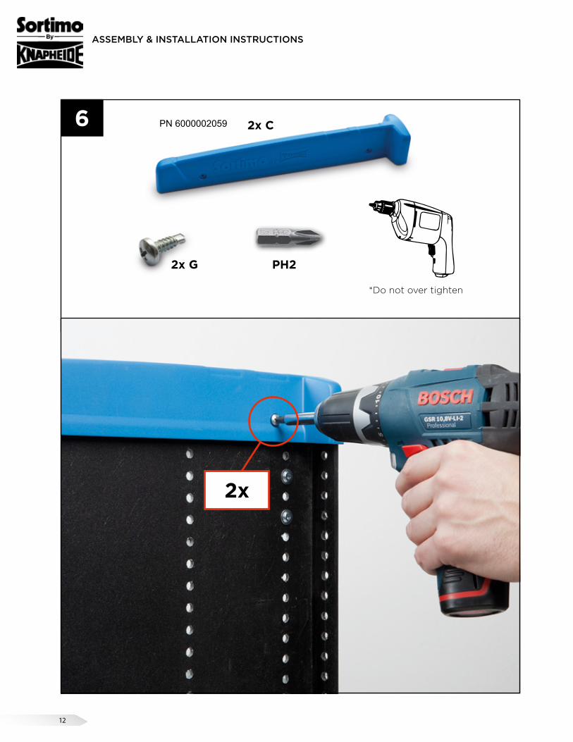
2x
2x G
*Do not over tighten
PH2
2x C6 PN 6000002059

13
ASSEMBLY & INSTALLATION INSTRUCTIONS
7
1. Insert plastic slide into the holes
2. Push it forward as far as it will go
3. Press plastic slide down until it snaps in.

14
ASSEMBLY & INSTALLATION INSTRUCTIONS
L2
L18
PN 1000002441 PN 1000002442
EcoFix bracket bending & mounting rules.
15
ASSEMBLY & INSTALLATION INSTRUCTIONS
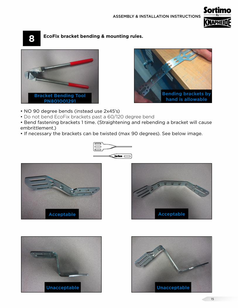
EcoFix bracket bending & mounting rules.
• NO 90 degree bends (instead use 2x45's)• Do not bend EcoFix brackets past a 60/120 degree bend• Bend fastening brackets 1 time. (Straightening and rebending a bracket will cause embrittlement.)• If necessary the brackets can be twisted (max 90 degrees). See below image.
Bracket Bending Tool PN801001291
Acceptable Acceptable
Unacceptable Unacceptable
Bending brackets by hand is allowable
8
09.03.2009 TU Allgemeine Einbauanleitung einer FE englisch – Index 01 12
Preparation/ fastening to the side wall
You can now adjust the fastening brackets. When bending the brackets please follow the guide lines below:
• No 90°-bendings (instead: 2x45°)
• Bend fastening bracket only once (embrittlement)
• Please observe bending radius (notch effect! Smallest permissible bending radius is 4mm)
• If necessary, the brackets can be twisted (max. 90°)
Please observe the difference between the fastening bracket in direction motion and the fastening bracket in thrust motion:
As many as possible fastening brackets should be fastened in direction motion. However, at least one fastening bracket should be fastened in thrust motion.
Fastening bracket in direction motion
Fasteningbracket in thrust
motion
Direction motion A combination of direction andthrust motion is o.k.
Fastening bracket in direction motion
Fasteningbracket in
thrust motion
Direction motion

16
ASSEMBLY & INSTALLATION INSTRUCTIONS
EcoFix bracket bending & mounting rules.
It is recommended to keep the EcoFix bracket on a horizontal plane when mounting it from the Exxpand unit to the wall. However, that is not always attainable. In this situation you are allowed to break the horizontal plane up to a 45 degree angle. See images below
Acceptable
Unacceptable
Horizontal Plane
Horizontal Plane
Horizontal Plane
45
45
Horizontal Plane
Horizontal Plane
8

17
ASSEMBLY & INSTALLATION INSTRUCTIONS
09.03.2009 TU Allgemeine Einbauanleitung einer FE englisch – Index 01 12
Preparation/ fastening to the side wall
You can now adjust the fastening brackets. When bending the brackets please follow the guide lines below:
• No 90°-bendings (instead: 2x45°)
• Bend fastening bracket only once (embrittlement)
• Please observe bending radius (notch effect! Smallest permissible bending radius is 4mm)
• If necessary, the brackets can be twisted (max. 90°)
Please observe the difference between the fastening bracket in direction motion and the fastening bracket in thrust motion:
As many as possible fastening brackets should be fastened in direction motion. However, at least one fastening bracket should be fastened in thrust motion.
Fastening bracket in direction motion
Fasteningbracket in thrust
motion
Direction motion A combination of direction andthrust motion is o.k.
Fastening bracket in direction motion
Fasteningbracket in
thrust motion
Direction motion
EcoFix BracketsExxpand
UnitInstallation
KitsDirectionalBrackets
Thrust Brackets
4450-1 2 1 14460-1 2 2 14460-2 1 1 14660-1 2 3 1
4480-1 3 3 24480-2 1 1 1
4680-1 3 4 24680-2 1 1 1
Directional & thrust motion brackets are required for mounting the Exxpand unit to the vehicle wall. The table below defines how many are required per unit size. Figures are derived from crash test data and should be closely adhered to.
A combination of direction and thrust motion is ok.
EcoFix bracket bending & mounting rules.8

ASSEMBLY & INSTALLATION INSTRUCTIONS
18
!
a
Note: The EcoFix mounting brackets must be attached to the
shelves or the supplied mounting adapter plate. They are not al-lowed to attach to the end panels only.
The mounting adapter plate is to be installed on the back of the unit and MUST be touching/spanning 2 shelves (see illustration below). Using existing/included hardware from the assembly hardware kit, you MUST fasten the bracket a minimum of two points on each shelf upper and lower (4 total points of contact). The hardware at ALL 4 mounting locations MUST go through the Shelf Staxx Stability Bracket, shelf staxx side panel AND SHELF. The same applies when using this bracket on an end panel that supports a -1 and -2, you must place hardware on both sides of the stability bracket (8 total points of contact, see illustration below). With the Exxpand Stability Mounting Adapter Plate correctly mounted, you are allowed to mount the EcoFix bracket anywhere on the adapter plate.

19
ASSEMBLY & INSTALLATION INSTRUCTIONS
D F
M
N
10
9
2x 2
D
M N D2x F
�� �
L1/L2
N D2x F
�� �
L1/L2
Primary Method
Secondary Method
Note: Primary Method: You must mount the EcoFix bracket to the end panel and a shelf. Secondary Method: Brackets may be attached to a shelf in certain situations. It is not allowed to attach the EcoFix brackets to the end panel only.
PN 71005206 PN 71003884

20
ASSEMBLY & INSTALLATION INSTRUCTIONS
IH
13
CAUTIONPrior to drilling, so as not to cut electric wires, fuel lines, brake lines etc., check behind and underneath drilling and mounting locations. Failure to heed this warning will result in death or serious injury.
ø 11
10
!
A
B
PN 71003988PN 71003987
21
ASSEMBLY & INSTALLATION INSTRUCTIONS
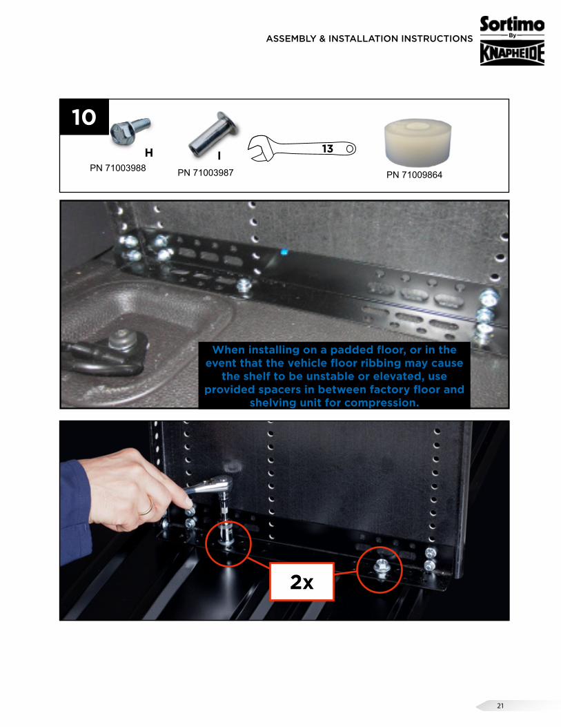
When installing on a padded floor, or in the event that the vehicle floor ribbing may cause
the shelf to be unstable or elevated, use provided spacers in between factory floor and
shelving unit for compression.
H 13
10
2x
IPN 71003988 PN 71003987 PN 71009864

22
ASSEMBLY & INSTALLATION INSTRUCTIONS
Whenever possible, the use of two rivnuts and bolts are required to anchor the EcoFix bracket to the vehicle.
11
23
ASSEMBLY & INSTALLATION INSTRUCTIONS
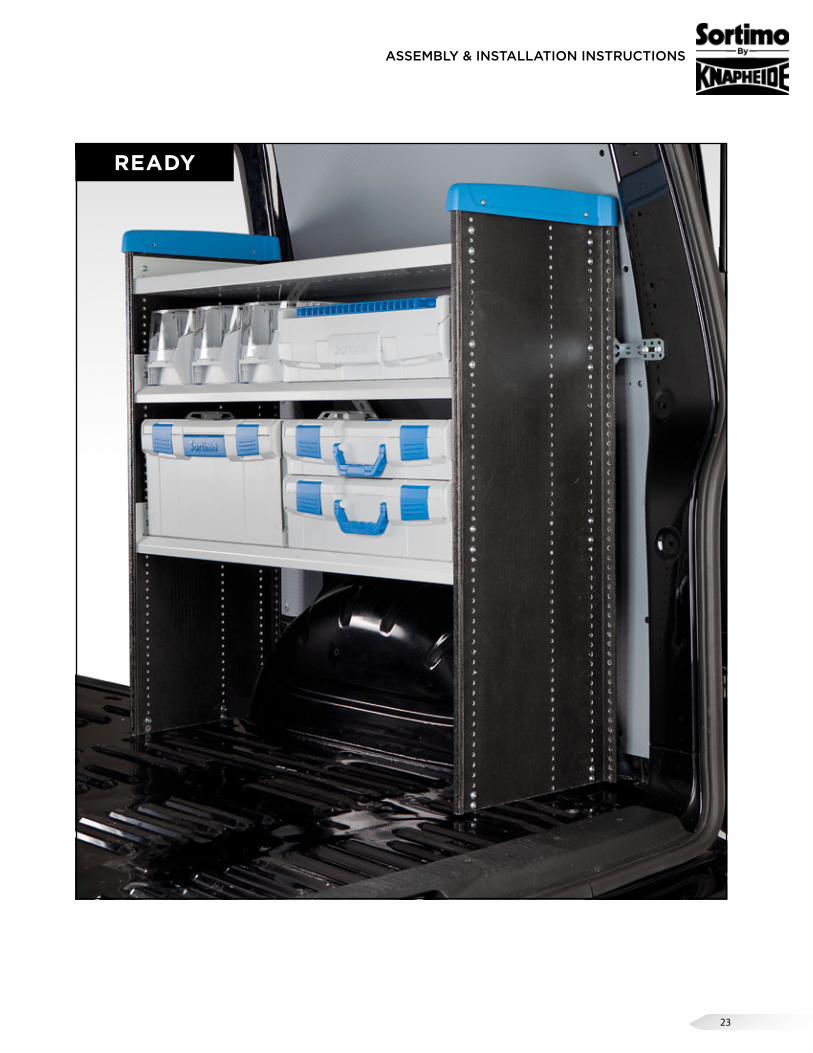
READY
24
VAN SPECIFIC INSTRUCTIONS
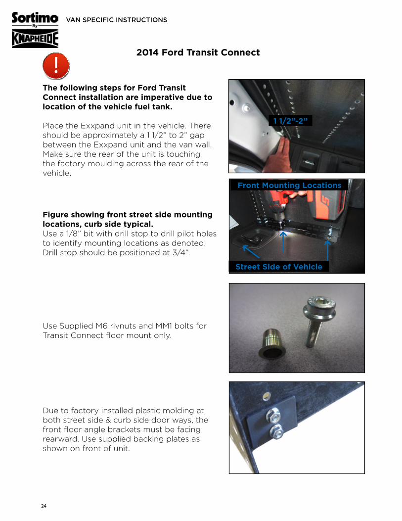
The following steps for Ford Transit Connect installation are imperative due to location of the vehicle fuel tank.
Place the Exxpand unit in the vehicle. There should be approximately a 1 1/2” to 2” gap between the Exxpand unit and the van wall. Make sure the rear of the unit is touching the factory moulding across the rear of the vehicle.
2014 Ford Transit Connect
Figure showing front street side mounting locations, curb side typical.Use a 1/8” bit with drill stop to drill pilot holes to identify mounting locations as denoted. Drill stop should be positioned at 3/4”.
Use Supplied M6 rivnuts and MM1 bolts for Transit Connect floor mount only.
Due to factory installed plastic molding at both street side & curb side door ways, the front floor angle brackets must be facing rearward. Use supplied backing plates as shown on front of unit.
1 1/2”-2”
Front Mounting Locations
Street Side of Vehicle
!

25
VAN SPECIFIC INSTRUCTIONS
Ram C/V
Chevrolet/ GMC Full Size Van
Curbside specific rear of block will require backing plates due to wheel well width.
Curb side of vehicle only will require the trimming of factory ductwork.
Using headliner as a guide, trim along the ductwork where ductwork meets factory headliner so that cut is flush.
Depending on whether your Ram C/V is equipped with Sortimo floor or aluminum floor will determine the mounting locations on the floor angle bracket.

26
ASSEMBLY & INSTALLATION INSTRUCTIONS
For fitting side panels to special requirements, we recommend following tools:
BOSCH-Order-Number
• Jig Saw 0 601 517 000
• Suction device 0 601 9C3 100
• Saw blade 2 608 667 450
PLEASE PAY ATTENTION
Cutting side panels harms stability of the racking, therefore, do not cut out a width (w) of more than 3.93 inches and a height (h) of more than 19.68 in-ches.
TECHNICAL NOTES
h
h
w w

27
ASSEMBLY & INSTALLATION INSTRUCTIONS
MAXIMUM LOAD
• Shelves 177.8 lbs
• Maximum area load 220 lbs
AREA
MAX. 220 lbs
ÈMAX. 220 lbs
ÈMAX. 220 lbs
È
BLOCK

28
ASSEMBLY & INSTALLATION INSTRUCTIONS
Grid L-BOXX LS-BOXX i-BOXX-Rack
10 Grid = 10 holes
12 Grid = 12 holes
18 Grid = 18 holes
21 Grid = 19 holes
22 Grid = 22 holes
26 Grid = 26 holes
31 Grid = 29 holes
Grid S-BOXX M-BOXX T-BOXX
8 Grid = 8 holes
12 Grid = 12 holes
29
ASSEMBLY & INSTALLATION INSTRUCTIONS
Grid L-BOXX LS-BOXX i-BOXX-Rack
10 Grid = 10 holes
12 Grid = 12 holes
18 Grid = 18 holes
21 Grid = 19 holes
22 Grid = 22 holes
26 Grid = 26 holes
31 Grid = 29 holes
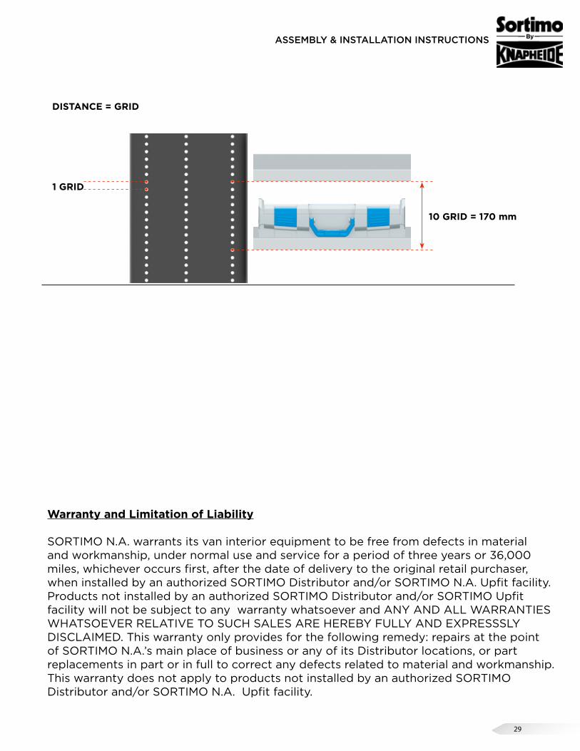
1 GRID
10 GRID = 170 mm
DISTANCE = GRID
Warranty and Limitation of Liability
SORTIMO N.A. warrants its van interior equipment to be free from defects in material and workmanship, under normal use and service for a period of three years or 36,000 miles, whichever occurs first, after the date of delivery to the original retail purchaser, when installed by an authorized SORTIMO Distributor and/or SORTIMO N.A. Upfit facility. Products not installed by an authorized SORTIMO Distributor and/or SORTIMO Upfit facility will not be subject to any warranty whatsoever and ANY AND ALL WARRANTIES WHATSOEVER RELATIVE TO SUCH SALES ARE HEREBY FULLY AND EXPRESSSLY DISCLAIMED. This warranty only provides for the following remedy: repairs at the point of SORTIMO N.A.’s main place of business or any of its Distributor locations, or part replacements in part or in full to correct any defects related to material and workmanship. This warranty does not apply to products not installed by an authorized SORTIMO Distributor and/or SORTIMO N.A. Upfit facility.