assembler.pdf · read this first msp430 family read this first this preface summarizes the...
TRANSCRIPT

Read This First MSP430 Family
Read This First
This preface summarizes the chapters, lists related documentation, and describes the styleand symbol conventions used in this manual.
How This Manual Is Organized
This document contains the following chapters:
Chapter 1 Introduction and InstallationProvides an overview of the assembly language development tools, awalkthrough, and installation information.
Chapter 2 Introduction to Common Object File FormatDiscusses the basic COFF concept of sections and how they can help youuse the assembler and linker more efficiently. Common object file format,or COFF, is the object file format used by the MSP430 family tools. ReadChapter before using the assembler and linker.
Chapter 3 Assembler DescriptionTells you how to invoke the assembler and discusses source statementformat, valid constants and expressions, and assembler output.
Chapter 4 Assembler DirectivesDivided into two parts: the first part describes the directives according tofunction, and the second part presents the directives in alphabetical order.
Chapter 5 Instruction Set SummarySummarizes the MSP430 instruction set alphabetically.
Chapter 6 Macro LanguageDescribes macro directives, substitution symbols used as macro para-meters, and how to create macros.
Chapter 7 Archiver DescriptionContains instructions for invoking the archiver, creating new archivelibraries, and modifying existing libraries.
Chapter 8 Linker DescriptionTells you how to invoke the linker, provides details about linker operation,discusses linker directives, and presents a detailed linking example.
Chapter 9 Absolute Lister DescriptionTells you how to invoke the absolute lister so that you can obtain a listing ofthe absolute addresses of an object file.
Chapter 10 Object Format Converter DescriptionTells you how to invoke the object format converter so that you can converta COFF object file into an Intel, Tektronix, or TI-tagged object format.

MSP430 Family Read This First
Appendix A Common Object File FormatContains supplemental technical data about the internal format andstructure of COFF object files.
Appendix B Symbolic Debugging DirectivesLists symbolic debugging directives that a high level language can use.
Appendix C Assembler Error MessagesLists the assembler error messages.
Appendix D Linker Error MessagesLists the linker error messages.
Appendix E ASCII Character SetProvides a table of the ASCII character set.
Appendix F GlossaryContains a glossary of terms and acronyms used in this book.
Appendix G Floating Point FormatsContains informations about the internal format of floating point constants.
Related Documentation
The following MSP430 documents are also available.
The MSP430 Family Data Manual (literature number SPNSxxx) discusses hardwareaspects of the MSP430, such as pin functions, architecture, stack operation, and inter-faces, and contains the MSP430 instruction set.
The MSP430 data sheets contain the recommended operating conditions, electricalspecifications, and timing characteristics of the MSP430 family devices.• MSP430C201 16–Bit Microcontroller Data Sheet (literature number SPNSxxx)

Read This First MSP430 Family
Style and Symbol Conventions
This document uses the following conventions:
• Program listings, program examples, and interactive displays are shown in a special font.Examples use a bold version of the special font for emphasis. Here is a sample programlisting:
1 0000 2δ ξ .βψτε 45 2 0001 2φ ψ .βψτε 47 3 0002 32 ζ .βψτε 50 4 0003 .τεξτ
• In syntax descriptions, the instruction, command, or directive is in a bold face font andparameters are in italics. Portions of a syntax that are in bold face should be entered asshown; portions of a syntax that are in italics describe the type of information that shouldbe entered. Here is an example of a directive syntax:
.space size
.space is the directive. This directive has one parameter, indicated by size. When youuse .space, the first and only parameter must be the size.
• Square brackets ( [ and ] ) identify an optional parameter. If you use an optionalparameter, you specify the information within the brackets; you don’t enter the bracketsthemselves. This is an example of an instruction that has an optional parameter:
.text [ address ]
• Braces ( { and } ) indicate a list. The symbol | (read as or) separates items within the list.Here’s an example of a list:
{ a | b | c }
This provides three choices: a, b, or c.
• Some directives can have a varying number of parameters. For example, the .bytedirective can have up to 100 parameters. The syntax for this directive is:
.byte value1 [, ... , valuen]
This syntax shows that .byte must have at least one value parameter, but you have theoption of supplying additional value parameters, separated by commas.

MSP430 Family Read This First
Following are other symbols and abbreviations used throughout this document.
Symbol Definition Symbol Definition
R0-R3 Registers with special functions R4-R15 Working registers, generalpurpose
PC Program counter register SP Stack pointer register
SR Status register CG1,CG2 Constant generator registers
LSB Least significant bit MSB Most significant bit
H,h Suffix – hexadecimal number B,b Suffix – binary integer
Q,q Suffix – octal integer
{ } List of parameters [ ] Optional parameter
text Indicates a “fill in the blank" – replace the text in italics with an appropriatesubstitute. For example, substitute an actual label for label; substitute an actualdestination expression for expression.
TrademarksIBM, IBM PC, IBM PC/XT, PC–DOS, IBM OS/2, and PS/2 are trademarks of International BusinessMachines Corp.MS, MS OS/2, MS–DOS, and MS–Windows are registered trademarks of Microsoft Corp.Sun–3, Sun–4, SunView, SunWindows, and Sun Workstation are trademarks of Sun Microsystems,Inc.UNIX is a registered trademark of AT&T Bell Laboratories, Inc.VAX and VMS are trademarks of Digital Equipment Corp.

MSP430 Family Introduction and Installation
1-1
Topics
1 Introduction and Installation 1-3
1.1 Development Tools Overview 1-4
1.2 Software Installation 1-61.2.1 Installing the Tools on IBM PC/ATs or 100% Compatible Machines With
PC–DOS, MS–DOS, or OS/2 1-6
1.3 Getting Started 1-7
Figures
Fig. Title Page1.1 MSP430 Assembly Language Development Flow 1-4

Introduction and Installation MSP430 Family
1-2

MSP430 Family Introduction and Installation
1-3
1 Introduction and Installation
The MSP430 devices are well supported by a full set of hardware and software developmenttools. This document discusses the software development tools included with the MSP430assembly language package:
• Assembler
• Archiver
• Linker
• Absolute Lister
• ROM Utility
These tools can be installed on the following systems:
• PC/AT with PC–DOS, MS–DOS, OS/2 or MS-Windows
The MSP430 assembly language tools create and use object files that are in common objectfile format (COFF) to facilitate modular programming. Object files contain separate blocks(called sections) of code and data that you can load into different MSP430 memory spaces.You will be able to program the MSP430 more efficiently if you have a basic understandingof COFF.

Introduction and Installation MSP430 Family
1-4
1.1 Development Tools Overview
The figure shows the assembly language development flow. The shaded portion highlightsthe most common development path; the other portions are optional.
Assembler Source
Assembler
COFF ObjectFiles
Linker
ExecutableCOFF Objekt
Files
MacroSource Files
Archiver
Macro Library
ObjectFormat
Converter
Archiver
Library ofObject Files
EPROMProgrammer
AbsoluteLister
MSP430SoftwareSimulator
EvaluationModule
In-CircuitEmulator
Figure 1.1: MSP430 Assembly Language Development Flow

MSP430 Family Introduction and Installation
1-5
• The assembler translates assembly language source files into machine language objectfiles. Source files can contain instructions, assembler directives, and macro directives.You can use assembler directives to control various aspects of the assembly process,such as the source listing format, symbol definition, and section content.
• The archiver allows you to collect a group of files into a single archive file. For example,you can collect several macros together into a macro library. The assembler will searchthrough the library and use only the members that are called as macros by the sourcefile. You can also use the archiver to collect a group of object files into an object library.The linker will include in the library the members that resolve external references duringthe link.
• The linker combines object files into a single executable object module. As it creates theexecutable module, it performs relocation and resolves external references. The linkeraccepts relocatable COFF object files (created by the assembler) as input. It alsoaccepts archiver library members and output modules created by a previous linker run.Linker directives allow you to combine object file sections, bind sections or symbols toaddresses or within memory ranges, and define or redefine global symbols.
• The absolute lister provides a file that can be reassembled to produce a listing of theabsolute addresses of an object file.
• The MSP430 microcontroller programmer accepts COFF files as input, but most EPROMprogrammers do not. The object format converter converts a COFF object file into TI–tagged, Intel, Motorola or Tektronix object format. The converted file can be downloadedto an EPROM programmer.
• The main purpose of this development process is to produce a module that can beexecuted in a system that contains a MSP430 device. You can use one of severaldebugging tools to refine and correct your code before downloading it to a MSP430system.

Introduction and Installation MSP430 Family
1-6
1.2 Software Installation
This section contains instructions for installing the assembly language tools.
1.2.1 Installing the Tools on IBM PC/ATs or 100% Compatible Machines With PC–DOS, MS–DOS, OS/2 or MS-Windows
The MSP430 assembly language software package is shipped on a double–sided, high–density disk. Your system must have at least 512K bytes of memory space and 1MB ofharddisk space.
First make a backup of the product disk.Insert the backup disk into the floppy disk drive of your choice.Change to that drive and enter:
INSTALL
Follow the instructions displayed on screen.

MSP430 Family Introduction and Installation
1-7
1.3 Getting Started
The tools you will probably use most often are the assembler and the linker. This sectionprovides a quick walkthrough so that you can get started without reading the whole user’sguide. These examples show the most common methods for invoking the assembler andlinker.
1) Create two short source files to use for the walkthrough; call them file1.asm andfile2.asm.
file1.asm file2.asm
.global addqstart clr R10 clr R11
loop call #addq jnc loop .end
.global addqaddq inc R10 inc R11
skp ret .end
2) Enter the following command to assemble file1.asm.
asm430 file1
3) The asm430 command invokes the MSP430 assembler; file1.asm is the input sourcefile.
If the input file extension is .asm, you don’t have to specify the extension; the assembleruses .asm as the default. This example creates an object file called file1.obj. Theassembler creates an object file only if there are no errors. You can specify a name forthe object file, but if you don’t, the assembler will append the .obj extension to the inputfilename.
4) Now assemble file2.asm; enter:
asm430 file2 -l
5) This time, the assembler creates an object file called file2.obj. The -l (lowercase “L")option tells the assembler to create a listing file; the listing file for this example is calledfile2.lst.
6) Link file1.obj and file2.obj; enter:
lnk430 file1 file2 -o prog.out
7) The lnk430 command invokes the linker. file1.obj and file2.obj are the input objectfiles. (If the input file extension is .obj, you don't have to specify the extension; the linkeruses .obj as the default.) The linker combines file1.obj and file2.obj to create anexecutable object module called prog.out. The -o option supplies the name of theoutput module.

Introduction and Installation MSP430 Family
1-8
MSP430 Family Introduction to COFF Format
2-1
Topics
2 Introduction to Common Object File Format 2-3
2.1 Sections 2-4
2.2 How the Assembler Handles Sections 2-62.2.1 Uninitialized Sections 2-62.2.2 Initialized Sections 2-72.2.3 Named Sections 2-72.2.4 Section Program Counters 2-82.2.5 An Example That Uses Sections Directives 2-8
2.3 How the Linker Handles Sections 2-112.3.1 Default Memory Allocation 2-122.3.2 Placing Sections in the Memory Map 2-13
2.4 Relocation 2-14
2.5 Runtime Relocation 2-15
2.6 Loading a Program 2-16
2.7 Symbols in a COFF File 2-172.7.1 External Symbols 2-172.7.2 The Symbol Table 2-17
Figures
Fig. Title Page2.1 Partitioning Memory Into Logical Blocks 2-5
2.2 Using Sections Directives 2-9
2.3 Generated Object Code according to previous source code example 2-10
2.4 Combining Input Sections to Form an Executable Object Module 2-12
2.5 An Example of Code That Generates Relocation Entries 2-14
Notes
Title Page2.1
Default Section Directive 2-6

Introduction to COFF Format MSP430 Family
2-2

MSP430 Family Introduction to COFF Format
2-3
2 Introduction to Common Object File Format
The assembler and linker create object files that can be executed by a MSP430 device. Theformat that these object files are in is called common object file format (COFF).
COFF makes modular programming easier because it encourages you to think in terms ofblocks of code and data when you write an assembly language program. These blocks areknown as sections. Both the assembler and the linker provide directives that allow you tocreate and manipulate sections.
For more information about COFF object file structure refer to the Appendix.

Introduction to COFF Format MSP430 Family
2-4
2.1 Sections
The smallest unit of an object file is called a section. A section is a block of code or data thatwill ultimately occupy contiguous space in the MSP430 memory map. Each section of anobject file is separate and distinct from the other sections. COFF object files always containthree default sections:
.text section usually contains executable code.
.data section usually contains initialized data.
.bss section usually reserves space for uninitialized variables.
In addition, the assembler and linker allow you to create, name, and link named sectionsthat are used like the .data, .text, and .bss sections.
It is important to note that there are two basic types of sections:
Initialized sections contain data or code. The .text and .data sections are initialized;named sections created with the .sect assembler directive are alsoinitialized.
Uninitialized sections reserve space in the memory map for uninitialized data. The .bsssection is uninitialized; named sections created with the .usect,reg, and .regpair assembler directive are also uninitialized.
The assembler provides several directives that allow you to associate various portions ofcode and data with the appropriate sections. The assembler builds these sections during theassembly process, creating an object file that is organized like the object file shown in thefollowing figure.
One of the linker’s functions is to relocate sections into the target memory map; this is calledallocation. Because most systems contain several different types of memory, using sectionscan help you to use target memory more efficiently. All sections are independentlyrelocatable; you can place different sections into various blocks of target memory. Forexample, you can define a section that contains an initialization routine and then allocate theroutine into a portion of the memory map that contains ROM.

MSP430 Family Introduction to COFF Format
2-5
Object File Target File
.bss
.data
.text
RAM
EEPROM
ROM
Figure 2.1: Partitioning Memory Into Logical Blocks

Introduction to COFF Format MSP430 Family
2-6
2.2 How the Assembler Handles Sections
The assembler’s main function related to sections is to identify the portions of an assemblylanguage program that belong in a particular section. The assembler has seven directivesthat support this function:
• .bss
• .data
• .sect
• .text
• .usect
The .bss and .usect directives create uninitialized sections; the .text, .data, and .sectdirectives create initialized sections.
Note: Default Section DirectiveIf you don´t use any of the sections directives, the assembler assembles everything intothe .text section.
2.2.1 Uninitialized Sections
Uninitialized sections reserve space in MSP430 memory; they are usually allocated intoRAM. These sections have no actual contents in the object file; they simply reserve memory.A program can use this space at runtime for creating and storing variables.
Uninitialized data areas are built by using the .bss and .usect assembler directives. The .bssdirective reserves space in the .bss section. The .usect directive reserves space in a specificuninitialized named section. If the section name is specified, the space is reserved in thenamed section. Each time you invoke one of these directives, the assembler reserves morespace in the appropriate section.
The syntaxes for these directives are:
.bss name [,size in bytes]
symbol .usect “section name", size in byte
symbol points to the first byte reserved by this invocation of the .bss or .usectdirective. The symbol corresponds to the name of the variable that you'rereserving space for. It can be referenced by any other section and can also bedeclared as a global symbol (with the .global assembler directive).
size is an absolute expression. The .bss directive reserves size bytes in the .bsssection; the .usect directive reserves size bytes in section name. If the sectionname is specified, the space is reserved in the named section.The default sizefor .bss is one byte.
section name tells the assembler which named section to reserve space in.

MSP430 Family Introduction to COFF Format
2-7
The .text, .data, and .sect directives tell the assembler to stop assembling into the currentsection and begin assembling into the indicated section. The .bss and .usect, however, donot end the current section and begin a new one; they simply “escape" from the currentsection temporarily. The .bss and .usect directives can appear anywhere in an initializedsection without affecting the contents of the initialized section.
2.2.2 Initialized Sections
Initialized sections contain executable code or initialized data. The contents of these sectionsare stored in the object file and placed in MSP430 memory when the program is loaded.Each initialized section is separately relocatable and may reference symbols that are definedin other sections. The linker automatically resolves these section–relative references.
Three directives tell the assembler to place code or data into a section. The syntaxes forthese directives are:
.text
.data
.sect “section name"
When the assembler encounters one of these directives, it stops assembling into the currentsection (acting as an implied “end current section" command). It then assembles subsequentcode into the respective section until it encounters another .text, .data, or .sect directive.
Sections are built up through an iterative process. For example, when the assembler firstencounters a .data directive, the .data section is empty. The statements following this first.data directive are assembled into the .data section (until the assembler encounters a .text or.sect directive). If the assembler encounters subsequent .data directives, it adds the state-ments following these .data directives to the statements that are already in the .data section.This creates a single .data section that can be allocated contiguously into memory.
2.2.3 Named Sections
Named sections are sections that you create. You can use them like the default .text, .data,and .bss sections, but they are assembled separately from the default sections.
For example, repeated use of the .text directive builds up a single .text section in the objectfile. When linked, this .text section is allocated into memory as a single unit. Suppose thereis a portion of executable code (perhaps an initialization routine) that you don't wantallocated with .text. If you assemble this segment of code into a named section, it will beassembled separately from .text, and you will be able to allocate it into memory separatelyfrom .text. Note that you can also assemble initialized data that is separate from the .datasection, and you can reserve space for uninitialized variables that is separate from the .bsssection.

Introduction to COFF Format MSP430 Family
2-8
Two directives let you create named sections:
• The .usect directive creates sections that are used like the .bss section. These sectionsreserve space in RAM for variables.
• The .sect directive creates sections that can contain code or data, similar to the default.text and .data sections. The .sect directive creates named sections with relocatableaddresses.
The syntaxes for these directives are:
symbol .usect “section name", size
.sect “section name"
The section name parameter is the name of the section. Section names are significant to 8characters. You can create up to 32,767 separate named sections.
Each time you invoke one of these directives with a new name, you create a new namedsection. Each time you invoke one of these directives with a name that was already used,the assembler assembles code or data (or reserves space) into the section with that name.You cannot use the same names with different directives. That is, you cannot create asection with the .usect directive and then try to use the same section with .sect.
2.2.4 Section Program Counters
The assembler maintains a separate program counter for each section. These programcounters are known as section program counters, or SPCs.
An SPC represents the current address within a section of code or data. Initially, theassembler sets each SPC to 0. As the assembler fills a section with code or data, itincrements the appropriate SPC. If you resume assembling into a section, the assemblerremembers the appropriate SPC’s previous value and continues incrementing the SPC atthat point.
The assembler treats each section as if it begins at address 0; the linker relocates eachsection according to its final location in the memory map.
2.2.5 An Example That Uses Sections Directives
The figure on the next page shows how you can build COFF sections incrementally, usingthe sections directives to swap back and forth between the different sections. You can usesections directives to:
• Begin assembling into a section for the first time.
• Continue assembling into a section that already contains code. In this case, theassembler simply appends the new code to the code that is already in the section.

MSP430 Family Introduction to COFF Format
2-9
The SPCs are modified during assembly. A line in a listing file has four fields:Field 1 contains the source code line counter.Field 2 contains the section program counter.Field 3 contains the object code.Field 4 contains the original source statement.
1 ********************************************** 2 ** Assemble an initialized table into .data ** 3 ********************************************** 4 0000 .data 5 0000 0011 coeff .word 011h, 022h 0002 0022 6 7 ********************************************** 8 ** Reserve space in .bss for a variable ** 9 ********************************************** 10 11 0000 .bss buffer, 10 12 ********************************************** 13 ** Still in .data ** 14 ********************************************** 15 16 0004 0123 ptr .word 0123h 17 ********************************************** 18 ** Assemble code into the .text section ** 19 ********************************************** 20 21 0000 .text 22 0000 5504 addl add R5,R4 23 0002 4304 clr R4 24 0004 ’23fd jnz addl 25 ********************************************** 26 ** Assemble more data into the .data section** 27 ********************************************** 28 29 0006 .data 30 0006 00aa ivals .word 0aah, 0bbh 0008 00bb 31 ********************************************** 32 ** define another section for more variables** 33 ********************************************** 34 35 0000 var2 .usect "newvars",1 36 0001 inbuf .usect "newvars",7 37 ********************************************** 38 ** Assembler more code into .text ** 39 ********************************************** 40 41 0006 .text 42 0006 4524 acode mov @R5, R4 43 0008 4407 mov R4, R7 44 ********************************************** 45 ** Define a named section for int. vectors ** 46 ********************************************** 47 48 0000 .sect "vectors" 49 0000 ’0000 .word addl, acode 0002 ’0006
Field 1 Field 2 Field 3 Field 4
Figure 2.2: Using Sections Directives

Introduction to COFF Format MSP430 Family
2-10
The listing file creates five sections:
.text contains 10 bytes of object code.
.data contains 10 bytes of object code.
vectors is a named section created with the .sect directive; it contains 4 bytes ofinitialized data.
.bss reserves 10 bytes in memory.
newvars is a named section created with the .usect directive; it reserves 8 bytes inmemory.
The second column shows the object code that is assembled into these sections; the firstcolumn shows the source statements that generated the object code.
5504430423FD45244407
00110022012300AA00BB
00000006
No data10 bytesreserved
No data8 bytesreserved
Object Code SectionLine Numbers2223244243
55163030
4949
11
35 36
.text
.data
vectors
.bss
newvars
Figure 2.3: Generated Object Code according to previous source code example

MSP430 Family Introduction to COFF Format
2-11
2.3 How the Linker Handles Sections
The linker has two main functions related to sections. First, the linker uses the sections inCOFF object files as building blocks; it combines input sections (when more than one file isbeing linked) to create output sections in an executable COFF output module. Second, thelinker chooses memory addresses for the output sections.
The linker provides two directives that support these functions:
• The MEMORY directive allows you to define the memory map of a target system. Youcan name portions of memory and specify their starting addresses and their lengths.
• The SECTIONS directive tells the linker how to combine input sections and where toplace the output sections in memory.
It is not always necessary to use linker directives. If you don’t use them, the linker uses thetarget processor’s default allocation algorithm. When you do use linker directives, you mustspecify them in a linker command file.

Introduction to COFF Format MSP430 Family
2-12
2.3.1 Default Memory Allocation
.bss
.text
.data
Init(named section)
.bss
.text
.data
Tables(named section)
file 1(.bss)
file 2(.bss)
file 1(.data)
file 2(.data)
file 1(.text)
file 2(.text)
Init
Tables
Init
Tables
ExecutableCode(.text)
InitializedData
(.data)
Space for
Variables
(.bss)
file1.obj
ExecutableObject Module Memory Map
file2.obj
Figure 2.4: Combining Input Sections to Form an Executable Object Module
In the figure, file1.obj and file2.obj have been assembled to be used as linker input. Eachcontains the .text, .data, and .bss default sections; in addition, each contains a namedsection. The executable output module shows the combined sections. The linker combinesfile1.text with file2.text to form one .text section, then combines the .data sections, then the.bss sections, and finally places the named sections at the end. The memory map showshow the sections are put into memory.

MSP430 Family Introduction to COFF Format
2-13
2.3.2 Placing Sections in the Memory Map
The figure also illustrates the linker’s default methods for combining sections. Sometimesyou may not want to use the default setup. For example, you may not want all of the .textsections to be combined into a single .text section. Or you might want a named sectionplaced where the .data section would normally be allocated. Most memory maps comprisevarious types of memories (RAM, ROM, EPROM, etc.) in varying amounts; you may want toplace a section in a particular type of memory.
• The MEMORY directive allows you to define the memory map for your particular system.
• The SECTIONS directive lets you build sections and place them into memory.

Introduction to COFF Format MSP430 Family
2-14
2.4 Relocation
The assembler treats each section as if it began at address 0. All relocatable symbols(labels) are relative to address 0 in their sections. Of course, all sections can’t actually beginat address 0 in memory, so the linker relocates sections by:
• allocating sections into the memory map so that they begin at the appropriate address.
• adjusting symbol values to correspond to the new section addresses.
• adjusting references to relocated symbols to reflect the adjusted symbol values.
The linker uses relocation entries to adjust references to symbol values. The assemblercreates a relocation entry each time a relocatable symbol is referenced. The linker then usesthese entries to patch the references after the symbols are relocated.
Figure 2.5: An Example of Code That Generates Relocation Entries
Both symbols x and y are relocatable. y is defined in the .text section of this module; x isdefined in some other module. When the code is assembled, x has a value of 0 (theassembler assumes all undefined external symbols have values of 0), and y has a value of 8(relative to address 0 in the .text section). The assembler generates two relocation entries,one for x and one for y. The reference to x is an external reference (indicated by the !character in the listing). The reference to y is to an internally defined relocatable symbol(indicated by the ’ character in the listing).
After the code is linked, suppose that x is relocated to address 7100h. Suppose also that the.text section is relocated to begin at address 7200h; y now has a relocated value of 7208h.The linker uses the two relocation entries to patch the two references in the object code:
40300000 br #x becomes 40307100
12B00008 call #y becomes 12B07208
Each section in a COFF object file has a table of relocation entries. The table contains onerelocation entry for each relocatable reference in the section. The linker usually removesrelocation entries after it uses them. This prevents the output file from being relocated again(if it is relinked or when it is loaded). A file that contains no relocation entries is an absolutefile (all its addresses are absolute addresses). If you want the linker to retain relocationentries, invoke the linker with the -r option.
1 .global x 2 0000 .text 3 0000 !40300000 br #x ;uses an external relocation 4 0004 ’12B00008 call #y ;uses an internal relocation 5 0008 5504 y: add R5, R4 ;defines internal relocation

MSP430 Family Introduction to COFF Format
2-15
2.5 Runtime Relocation
It may be necessary or desirable at times to load code into one area of memory and run it inanother. For example, you may have performance–critical code in a ROM–based system.The code must be loaded into ROM but would run much faster if it were in RAM.
The linker provides a simple way to specify this. In the SECTIONS directive, you canoptionally direct the linker to allocate a section twice: once to set its load address, and againto set its run address.
Use the load keyword for the load address and the run keyword for the run address.
The load address determines where a loader will place the raw data for the section. Anyreferences to the section (such as labels in it) refer to its run address. The application mustcopy the section from its load address to its run address; this does not happen automaticallyjust because you specify a separate run address.
If you provide only one allocation (either load or run) for a section, the section is allocatedonly once and will load and run at the same address. If you provide both allocations, thesection is actually allocated as if it were two different sections of the same size.
Uninitialized sections (such as .bss) are not loaded, so the only significant address is the runaddress. The linker allocates uninitialized sections only once: if you specify both run andload addresses, the linker warns you and ignores the load address.

Introduction to COFF Format MSP430 Family
2-16
2.6 Loading a Program
The linker produces executable COFF object modules. An executable object file has thesame COFF format as object files that are used as linker input; however, the sections in anexecutable object file are combined and relocated to fit into target memory.
In order to run a program, the data in the executable object module must be transferred, orloaded, into target system memory.
Several methods can be used for loading a program, depending on the executionenvironment. Some of the more common situations are listed below.
• The MSP430 development tools (In-Circuit-Emulator and Evaluation Module) provideCOFF object module loading capabilities.
• You can use the object format converter (the rom430, which is shipped as part of theassembly language package) to convert the executable COFF object module into one ofseveral object file formats. You can then use the converted file with almost any EPROMprogrammer to burn the program into an EPROM.

MSP430 Family Introduction to COFF Format
2-17
2.7 Symbols in a COFF File
A COFF file contains a symbol table that stores information about symbols in the program.The linker uses this table when it performs relocation. Debugging tools can also use thesymbol table to provide symbolic debugging.
2.7.1 External Symbols
External symbols are symbols that are defined in one module and referenced in anothermodule. You can use the .def, .ref, or .global directives to identify symbols as external:
Defined (.def) Defined in the current module and used in another module
Referenced (.ref) Referenced in the current module, but defined in another module
Global (.global) May be either of the above
The following code segment illustrates these definitions.
x: ADD #56h, R4 ; Define xBR #y ; Reference y.global x ; DEF of x.global y ; REF of y
The .global definition of x says that it is an external symbol defined in this module and thatother modules can reference x. The .global definition of y says that it is an undefined symbolthat is defined in some other module.
The assembler places both x and y in the object file’s symbol table. When the file is linkedwith other object files, the entry for x defines unresolved references to x from other files. Theentry for y causes the linker to look through the symbol tables of other files for y’s definition.
The linker must match all references with corresponding definitions. If the linker cannot find asymbol’s definition, it prints an error message about the unresolved reference. This type oferror prevents the linker from creating an executable object module.
2.7.2 The Symbol Table
The assembler always generates an entry in the symbol table when it encounters an externalsymbol (both definitions and references). The assembler also creates special symbols thatpoint to the beginning of each section; the linker uses these symbols to relocate referencesto other symbols in a section.
The assembler does not usually create symbol table entries for any other type of symbol,because the linker does not use them. For example, labels are not included in the symboltable unless they are declared with .global. For symbolic debugging purposes, it issometimes useful to have entries in the symbol table for each symbol in a program. Toaccomplish this, invoke the assembler with the -s option.

Introduction to COFF Format MSP430 Family
2-18

MSP430 Family Assembler Description
3-1
Topics
3 Assembler Description 3-3
3.1 Assembler Development Flow 3-4
3.2 Invoking the Assembler 3-5
3.3 Naming Alternate Directories for Assembler Input 3-73.3.1 -i Assembler Option 3-73.3.2 Environment Variable (A_DIR) 3-8
3.4 Source Statement Format 3-9
3.5 Constants 3-12
3.6 Character Strings 3-14
3.7 Symbols 3-15
3.8 Expressions 3-183.8.1 Operators 3-193.8.2 Expression Overflow and Underflow 3-193.8.3 Well–Defined Expressions 3-203.8.4 Conditional Expressions 3-203.8.5 Relocatable Symbols and Legal Expressions 3-20
3.9 Source Listings 3-23
3.10 Cross–Reference Listings 3-26
Examples
Ex. Title Page3.1 An Assembler Listing 3-25
3.2 An Assembler Cross–Reference Listing 3-26
Figures
Fig. Title Page3.1 Assembler Development Flow 3-4
Tables
Table Title Page3.1 Operators Used in Expressions (Precedence) 3-19
3.2 Expressions With Absolute and Relocatable Symbols 3-21
3.3 Symbol Attributes 3-26

Assembler Description MSP430 Family
3-2

MSP430 Family Assembler Description
3-3
3 Assembler Description
The assembler translates assembly language source files into machine language object files.These files are in common object file format (COFF). Source files can contain the followingassembly language elements:
Assembler directives
Assembly language instructions
Macro directives
This two–pass assembler does the following:
• Processes the source statements in a text file to produce a relocatable object file.
• Produces a source listing (if requested) and provides you with control over this listing.
• Allows you to segment your code into sections and maintain an SPC (section programcounter) for each section of object code.
• Defines and references global symbols and appends a cross–reference listing to thesource listing (if requested).
• Assembles conditional blocks.
• Supports macros, allowing you to define macros inline or in a library.

Assembler Description MSP430 Family
3-4
3.1 Assembler Development Flow
The figure illustrates the assembler’s role in the assembly language development flow. Theassembler accepts assembly language source files as input.
Assembler Source
Assembler
COFF ObjectFiles
Linker
ExecutableCOFF Objekt
Files
MacroSource Files
Archiver
Macro Library
ObjectFormat
Converter
Archiver
Library ofObject Files
EPROMProgrammer
AbsoluteLister
MSP430SoftwareSimulator
EvaluationModule
In-CircuitEmulator
Figure 3.1: Assembler Development Flow

MSP430 Family Assembler Description
3-5
3.2 Invoking the Assembler
To invoke the assembler, enter the following:
asm430 [input file [object file [listing file [ rawdata file]]]] [-options]
asm430 is the command that invokes the assembler.
input file names the assembly language source file. If you do not supply an extension, theassembler assumes that the input file has the default extension .asm. If you donot supply an input filename when you invoke the assembler, the assembler willprompt you for one.
object file names the object file that the assembler creates. If you do not supply anextension, the assembler uses .obj as a default extension. If you do not supplyan object file, the assembler creates a file that uses the input file name with the.obj extension.
listing file names the optional listing file that the assembler can create. If you do not supplya name for a listing file, the assembler does not create one unless you use the -loption. In this case, the assembler uses the input filename. If you do not supplyan extension, the assembler uses .lst as a default extension.
rawdata file names the optional ascii-format object file that the assembler can create. If youdo not supply a name for the rawdata file, the assembler does not create oneunless you use the -z option. In this case, the assembler uses the input filename.If you do not supply an extension, the assembler uses .txt as a default extension
options identifies the assembler options that you want to use.
Options are not case–sensitive and can appear anywhere on the command linefollowing the command. Precede each option with a hyphen (-). You can stringthe options together; for example, -lc is equivalent to -l -c. The valid assembleroptions are as follows:
-a creates an absolute listing. When you use -a, the assembler does notproduce an object file. The absolute listing option is used in conjunctionwith the absolute lister.
-b suppress banner on all pages except page 1.
-c makes case insignificant. For example, the symbols ABC and abc will beequivalent. If you do not use this option, case is significant.
-i specifies a directory where the assembler can find files named by the.copy, .include, or .mlib directives. The format of the -i option is -ipath-name. You can specify up to 10 directories in this manner; each path-name must be preceded by the -i option.
-l (lowercase “L") produces a listing file.
-q (quiet) suppresses the banner and all progress information.

Assembler Description MSP430 Family
3-6
-s puts all defined symbols in the object file’s symbol table. Usually, theassembler puts only global symbols into the symbol table. When you use-s, symbols that are defined as labels or as assembly–time constants arealso placed in the symbol table.
-x produces a cross–reference table and appends it to the end of the listingfile. If you do not request a listing file, the assembler creates one anyway.
-z creates an objext file in ascii format containing no relocation and debuginformation. The generation of the COFF object file is not affected. Thisoption is used in conjunction with the evaluation module.

MSP430 Family Assembler Description
3-7
3.3 Naming Alternate Directories for Assembler Input
The .copy, .include, and .mlib directives tell the assembler to use code from external files.The .copy and .include directives tell the assembler to read source statements from anotherfile, and the .mlib directive names a library that contains macro functions. The syntaxes forthese directives are:
.copy "filename"
.include "filename"
.mlib "filename"
The filename names a copy/include file that the assembler reads statements from or amacro library that contains macro definitions. The filename may be a complete pathname, apartial pathname, or a filename with no path information. The assembler searches for the filein:
1) The directory that contains the current source file. The current source file is the file beingassembled when the .copy, .include, or .mlib directive is encountered.
2) Any directories named with the -i assembler option.
3) Any directories set with the environment variable A_DIR.
You can augment the assembler’s directory search algorithm by using the -i assembleroption or the A_DIR environment variable.
3.3.1 -i Assembler Option
The -i assembler option names an alternate directory that contains copy/include files ormacro libraries. The format of the -i option is as follows:
asm430 -ipathname source filename
You can use up to 10 -i options per invocation; each -i option names one pathname. Inassembly source, you can use the .copy, .include, or .mlib directive without specifying anypath information. If the assembler doesn’t find the file in the directory that contains thecurrent source file, it searches the paths provided by the -i options.
For example, assume that a file called source.asm is in the current directory; source.asmcontains the following directive statement:
.copy "copy.asm"

Assembler Description MSP430 Family
3-8
Pathname for copy.asm Invocation Command
DOS c:\430\files\copy.asm asm430 -ic:\430\files source.asm
The assembler first searches for copy.asm in the current directory because source.asm is inthe current directory. Then, the assembler searches in the directory named with the -i option.
3.3.2 Environment Variable (A_DIR)
An environment variable is a system symbol that you define and assign a string to. Theassembler uses the environment variable A_DIR to name alternate directories that containcopy/include files or macro libraries. The command for assigning the environment variable isas follows:
DOS set A_DIR = pathname;another pathname ...
The pathnames are directories that contain copy/include files or macro libraries. You canseparate the pathnames with a semicolon or with blanks. In assembly source, you can usethe .copy, .include, or .mlib directive without specifying any path information. If the assemblerdoesn’t find the file in the directory that contains the current source file or in directoriesnamed by -i, it searches the paths named by the environment variable.
For example, assume that a file called source.asm contains these statements:
.copy "copy1.asm"
.copy "copy2.asm"
Pathname Invocation Command
DOS c:\430\files\copy1.asmc:\dsys\copy2.asm
set A_DIR=c:\dsys; c:\exec\sourceasm430 -ic:\430\files source.asm
The assembler first searches for copy1.asm and copy2.asm in the current directory becausesource.asm is in the current directory. Then the assembler searches in the directory namedwith the -i option and finds copy1.asm. Finally, the assembler searches the directory namedwith A_DIR and finds copy2.asm.
Note that the environment variable remains set until you reboot the system or reset thevariable by entering one of these commands:
DOS set A_DIR=

MSP430 Family Assembler Description
3-9
3.4 Source Statement Format
MSP430 assembly language source programs consist of source statements that can containassembler directives, assembly language instructions, macro directives, and comments.Source statement lines can be as long as the source file format allows, but the assemblerreads up to 200 characters per line. If a statement contains more than 200 characters, theassembler truncates the line and issues a warning.
The next several lines show examples of source statements:
sym .equ 2 ; Symbol sym = 2Begin: ADD #sym+5,R11 ; Add (sym+5) to contents of R11
.word 016h ; Initialize a word with 016h
A source statement can contain four ordered fields. The general syntax for sourcestatements is as follows:
[label] [:] mnemonic [operand list] [;comment]
Follow these guidelines:
• All statements must begin with a label, a blank, an asterisk, or a semicolon.
• Labels are optional; if used, they must begin in column 1.
• One or more blanks must separate each field. Note that tab characters are equivalent toblanks.
• Comments are optional. Comments that begin in column 1 can begin with an asterisk ora semicolon (* or ;), but comments that begin in any other column must begin with asemicolon.
Label Field
Labels are optional for all assembly language instructions and for most (but not all)assembler directives. When used, a label must begin in column 1 of a source statement. Alabel can contain up to 32 alphanumeric characters (A-Z, a-z, 0-9, _, and $). Labels arecase–sensitive, and the first character cannot be a number. A label can be followed by acolon (:); the colon is not treated as part of the label name. If you don't use a label, the firstcharacter position must contain a blank, a semicolon, or an asterisk.
When you use a label, its value is the current value of the section program counter (the labelpoints to the statement it's associated with). If, for example, you use the .word directive toinitialize several words, a label would point to the first word. In the following example, thelabel Start has the value 40h.
. . . .
. . . .
. . . .9 003F * Assume some other code was assembled10 0040 000A Start: .word 0Ah,3,7 0041 0003 0043 0007

Assembler Description MSP430 Family
3-10
A label on a line by itself is a valid statement. It assigns the current value of the sectionprogram counter to the label; this is equivalent to the following directive statement:
label .equ $ ; $ provides the current value of the SPC
When a label appears on a line by itself, it points to the instruction on the next line (the SPCis not incremented):
3 0050 Here:4 0050 0003 .word 3
Mnemonic Field
The mnemonic field follows the label field. The mnemonic field cannot start in column 1, or itwould be interpreted as a label. The mnemonic field can contain one of the followingopcodes:
• Machine–instruction mnemonic (such as ADC, MOV, POP)
• Assembler directive (such as .data, .list, .equ)
• Macro directive (such as .macro, .var, .mexit)
• A macro call
Operand Field
The operand field is a list of operands that follow the mnemonic field. An operand can be aconstant, a symbol, or a combination of constants and symbols in an expression. You mustseparate operands with commas.
• Operand Prefixes for Instructions
The assembler allows you to specify that a constant, symbol, or expression should beused as an address, an immediate value, or an indirect value. The following rules applyto the operands of instructions.
• No prefix — the operand is an address or a register . If you do not use a prefixwith an operand, the assembler treats an operand representing a constant value asan absolute address. When the operand is a label, the assembler generates asymbolic address. A register name specifies the contents of the named register. Thisare examples of instructions that use operands without prefixes:
Label: ADD 0FFFEh,R5 ; add contents of absolute address to register ADD Label,R5 ; add contents of symbolic address to register
• & prefix — the operand is an absolute address . If you use the & sign as a prefix,the assembler treats the operand as an absolute address, similar to using no prefix.The operand has to specify a constant value:
MOV &200h,R5 MOV 200h,R5
Both instructions generate the same object code, moving the contents of absoluteaddress 200h to register R5.

MSP430 Family Assembler Description
3-11
• # prefix — the operand is an immediate value . If you use the # sign as a prefix, theassembler treats the operand as an immediate value. This is true even when theoperand is an address; the assembler treats the address as a value instead of usingthe contents of the address. This is an example of an instruction that uses anoperand with the # prefix:
Label: ADD #123,R5
The operand #123 is an immediate value. The assembler adds 123 (decimal) to thecontents of register R5.
• @ prefix — the operand is an indirect address. If you use the @ sign as a prefix,the assembler treats the operand as an indirect address; that is, it uses the contentsof the operand as an address. This is an example of an instruction that uses anoperand with the @ prefix:
Label: MOV @R4,R4
The operand @R4 specifies an indirect address. The assembler goes to the addressspecified by the contents of register R4 and then moves the contents of that locationto register R4.
• Immediate Addressing for Directives
The immediate addressing mode is used mostly with instructions; in some cases, it canalso be used with the operands of directives.
Usually, it is not necessary to use the immediate addressing mode for directives.Compare the following statements:
ADD #10, R4
.byte 10
In the first statement, the immediate addressing mode is necessary to tell the assemblerto add the value 10 to register R4. In the second statement, however, immediateaddressing is not used; the assembler expects the operand to be a value and initializes abyte with the value 10.
Comment Field
A comment can begin in any column and extends to the end of the source line. A commentcan contain any ASCII character, including blanks. Comments are printed in the assemblysource listing, but they do not affect the assembly.
A source statement that contains only a comment is valid. If it begins in column 1, it can startwith a semicolon ( ; ) or an asterisk ( *). Comments that begin anywhere else on the linemust begin with a semicolon. The asterisk identifies a comment only if it appears in column1.

Assembler Description MSP430 Family
3-12
3.5 Constants
The assembler supports six types of constants:
• Binary integer constants• Octal integer constants• Decimal integer constants• Hexadecimal integer constants• Character constants• Assembly–time constants
The assembler maintains each constant internally as a 32–bit quantity. Note that constantsare not sign extended. For example, the constant 0FFH is equal to 00FF (base 16) or 255(base 10); it does not equal -1.
Binary Integers
A binary integer constant is a string of up to 16 binary digits (0s and 1s) followed by the suffixB (or b). If fewer than 16 digits are specified, the assembler right–justifies the value andzero–fills the unspecified bits. These are examples of valid binary constants:
00000000BConstant equal to 010 or 0160100000b Constant equal to 3210 or 201601b Constant equal to 110 or 11611111000BConstant equal to 24810 or 0F816
Octal Integers
An octal integer constant is a string of up to 6 octal digits (0 through 7) followed by the suffixQ (or q). These are examples of valid octal constants:
10Q Constant equal to 810 or 816100000Q Constant equal to 32,76810 or 800016226Q Constant equal to 15010 or 9616
Decimal Integers
A decimal integer constant is a string of decimal digits, ranging from? -32,768 to 65,535.These are examples of valid decimal constants:
1000 Constant equal to 100010 or 3E816-32768 Constant equal to -32,76810 or 80001625 Constant equal to 2510 or 1916
Hexadecimal Integers
A hexadecimal integer constant is a string of up to 4 hexadecimal digits followed by the suffixH (or h). Hexadecimal digits include the decimal values 0-9 and the letters A-F or a-f. A

MSP430 Family Assembler Description
3-13
hexadecimal constant must begin with a decimal value (0-9). If fewer than 4 hexadecimaldigits are specified, the assembler right–justifies the bits. These are examples of validhexadecimal constants:
78h Constant equal to 12010 or 0078160Fh Constant equal to 1510 or 000F1637ACh Constant equal to 14,25210 or 37AC16
Character Constants
A character constant is a single character enclosed in single quotes. The characters arerepresented internally as 8–bit ASCII characters. Two consecutive single quotes are requiredto represent each single quote that is part of a character constant. A character constantconsisting only of two single quotes is valid and is assigned the value 0. These are examplesof valid character constants:
'a' Defines the character constant a and is represented internally as 6116'C' Defines the character constant C and is represented internally as 4316'''' Defines the character constant "" and is represented internally as 2716'' Defines a null character and is represented internally as 0016
Note the difference between character constants and character strings. A character constantrepresents a single integer value; a string is a list of characters.
Assembly-Time Constants
If you use the .equ directive to assign a value to a symbol, the symbol becomes a constant.In order to use this constant in expressions, the value that is assigned to it must be absolute.For example:
sym .equ 3MOV #sym,R10
You can also use the .equ directive to assign symbolic constants for register names. In thiscase, the symbol becomes a synonym for the register:
sym .equ R14MOV #10,sym

Assembler Description MSP430 Family
3-14
3.6 Character Strings
A character string is a string of characters enclosed in double quotes. Double quotes that arepart of character strings are represented by two consecutive double quotes. The maximumlength of a string varies and is defined for each directive that requires a character string.Characters are represented internally as 8–bit ASCII characters. Appendix lists validcharacters.
These are examples of valid character strings:
"sample program" defines a 14–character string, sample program
"PLAN ""C""" defines an 8–character string, PLAN "C"
Character strings are used for the following:
• Filenames, as in .copy "filename"
• Section names, as in .sect "section name"
• Data initialization directives, as in .byte "charstring"
• Operand of .string or .byte directive

MSP430 Family Assembler Description
3-15
3.7 Symbols
Symbols are used as labels, constants, and substitution symbols. A symbol name is a stringof up to 32 alphanumeric characters (A-Z, a-z, 0-9, $, _and?). The first character in asymbol cannot be a number; symbols cannot contain embedded blanks. The symbols youdefine are case sensitive; for example, the assembler recognizes ABC, Abc, and abc asthree unique symbols. You can override case sensitivity with the -c assembler option. Thistype of symbol is valid only during the assembly in which it is defined, unless you use the.global directive to declare it as an external symbol.
Labels
Symbols that are used as labels become symbolic addresses that are associated withlocations in the program. A label used locally within a file must be unique. Mnemonic op-codes and assembler directive names (without the _‘.’ prefix) are valid label names.
Labels can also be used as the operand of a .global, .ref, .def, or .bss directive; for example:
.global label1
label2 nopmov label1, R4br label2
Local Labels
Local labels are a special type of label whose scope and effect are only temporary. A locallabel has the form $n, where n is a decimal digit in the range 0-9. For example, $4 and $1are valid local labels.
Normal labels must be unique (they can be declared only once), and they can be used asconstants in the operand field. Local labels, however, can be undefined and defined again. Ifa local label is used as an operand, it can be used only as an operand for a 10–bit jumpinstruction.
A local label can be undefined, or reset, in one of four ways:
• By the .newblock directive
• By changing sections (using a .sect, .text, or .data directive)
• By entering an include file (specified by the .include or .copy directive)
• By leaving an include file (specified by the .include or .copy directive)

Assembler Description MSP430 Family
3-16
This is an example of code that declares and uses a local label legally:
Label1: mov R12,R13jnz $1mov #–1,R13
$1 cmp R13,R4.newblock; Undefine $1 so it can be used againjne $1inc R13
$1 add R13,R14
The following code uses a local label illegally:
Label1: mov R12,R13jnz $1mov #–1,R13
$1 cmp R3,R4jne $1inc R13
$1 add R13,R14 ; WRONG — $1 is multiply defined
Local labels are especially useful in macros. If a macro contains a normal label and is calledmore than once, the assembler issues a multiple–definition error. However, if you use alocal label within a macro and then use .newblock within the macro, the local label is usedand reset each time the macro is expanded.
Up to ten local labels can be in effect at one time. After you undefine a local label, you candefine it and use it again. Local labels do not appear in the object code symbol table.
Constants
Symbols can be set to constant values. By using constants, you can equate meaningfulnames with constant values. The .equ, .set, and .struct/.tag/.endstruct directives enable youto set constants to symbolic names. Symbolic constants cannot be redefined. The followingexample shows how these directives can be used:
K .set 1024 ; constant definitionsmaxbuf .set 2*K
item .struct ; item structure definition.byte value ; constant offsets value = 0.byte delta ; constant offsets delta = 1
i_len .endstruct
array .tag item ; array declaration.bss array, i_len*K
MOV array.delta,R4 ; array+1
The assembler also has several predefined symbolic constants; these are discussed in thenext subsection.

MSP430 Family Assembler Description
3-17
Symbolic Constants
The assembler has several predefined symbols, including the following:
• $, the dollar sign character, represents the current value of the section program counter(SPC).
• Register symbols, which are of the form Rn or rn , where n is an expression thatevaluates in the range 0-15. (If the number is greater than 15, the symbol is notconsidered a register symbol.) The number may be decimal. Note that PC, SP and SRare valid register symbols; they represent registers with special functions (R0 - R3).
Substitutions Symbols
Symbols can be assigned a string value (variable). This enables you to alias characterstrings by equating them to symbolic names. Symbols that represent character strings arecalled substitution symbols. When the assembler encounters a substitution symbol, its stringvalue is substituted for the symbol name. Unlike symbolic constants, substitution symbolscan be redefined.
A string can be assigned to a substitution symbol anywhere within a program; for example:
.asg "R13", SP1
.asg "+", pls
.asg "-5", min5
ADD # min5,SP1
When you are using macros, substitution symbols are important because macro parametersare actually substitutions symbols that are assigned a macro argument. The following codeshows how substitution symbols are used in macros:
add2 .macro src,dest ; add2 macro definition
mov src,R4mov R4,R5mov dest,R4add R5,R4mov R4,dest
.endm
*add2 invocationadd2 loc1, loc2

Assembler Description MSP430 Family
3-18
3.8 Expressions
An expression is a constant, a symbol, or a series of constants and symbols separated byarithmetic operators. The range of valid expression values is -32,768 to 65,535. These arethe three main factors that influence the order of expression evaluation:
Parentheses Expressions that are enclosed in parentheses are alwaysevaluated first.
8/(4/2) = 4, but 8/4/2 = 1
Note that you cannot substitute braces ( { } ) or brackets ( [ ] )for parentheses.
Precedence groups Operators, listed in the next table, are divided into nineprecedence groups. When the order of expression evaluation isnot determined by parentheses, the highest precedenceoperation is evaluated first.
8 + 4/2 = 10 (4/2 is evaluated first)
Left–to–right evaluation When parentheses and precedence groups do not determinethe order of expression evaluation, the expressions areevaluated from left to right. Note that the highest precedencegroup is evaluated from right to left.
8/4*2 = 4, but 8/(4*2) = 1

MSP430 Family Assembler Description
3-19
3.8.1 Operators
Group Operator Description
1 +-~!
Unary plusUnary minus1s complementLogical NOT
2 */
%
MultiplicationDivisionModulo
3 +-
AdditionSubtraction
4 <<>>
Shift leftShift right
5 <<=>
>=
Less thanLess than or equal toGreater thanGreater than or equal to
6 = (==)!= (<>)
Equal toNot equal to
7 & Bitwise AND
8 ^ Bitwise XOR
9 | Bitwise OR
Notes: 1) Operators in parentheses ( ) indicate an alternate form.2) Group 1 operators are evaluated right to left. All other operators
are evaluated left to right.
Table 3.1: Operators Used in Expressions (Precedence)
3.8.2 Expression Overflow and Underflow
The assembler checks for overflow and underflow conditions when arithmetic operations areperformed at assembly time. The assembler issues a Value Truncated warning whenever anoverflow or underflow occurs. The assembler does not check for overflow or underflow inmultiplication.

Assembler Description MSP430 Family
3-20
3.8.3 Well–Defined Expressions
Some assembler directives require well–defined expressions as operands. Well–definedexpressions contain only symbols or assembly–time constants that are defined before theyare encountered in the expression. The evaluation of a well–defined expression must beabsolute.
This is an example of a well–defined expression:
1000h+X
where X was previously defined as an absolute symbol.
3.8.4 Conditional Expressions
The assembler supports relational operators that can be used in any expression; they areespecially useful for conditional assembly. Relational operators include the following:
= Equal to = = Equal to! = Not equal to <> Not Equal to< Less than < = Less than or equal to> Greater than > = Greater than or equal to
Conditional expressions evaluate to 1 if true and 0 if false, and may be used only onoperands of equivalent types, e.g., absolute value compared to absolute value, but notabsolute value compared to relocatable value.
3.8.5 Relocatable Symbols and Legal Expressions
The following table summarizes valid operations on absolute, relocatable, and externalsymbols. An expression cannot multiply or divide by a relocatable or external symbol. Anexpression cannot contain unresolved symbols that are relocatable with respect to differentsections.
Symbols that have been defined as global with the .global directive can also be used inexpressions; in the table, these symbols are referred to as external.

MSP430 Family Assembler Description
3-21
If A is... If B is... A + B is... A - B is...
absolute absolute absolute absolute
absolute relocatable relocatable illegal
absolute external external illegal
relocatable absolute relocatable relocatable
relocatable relocatable illegal absolute *
relocatable external illegal illegal
external absolute external external
external relocatable illegal illegal
external external illegal illegal
* A and B must be in the same section; otherwise, this is illegal.
Table 3.2: Expressions With Absolute and Relocatable Symbols
Here are some examples of expressions that use relocatable and absolute symbols. Theseexamples use four symbols that are defined in the same section:
.global extern_1 ;Defined in an external moduleintern_1: .word ’D’ ;Relocatable, defined in current moduleLAB1: .equ 2 ;LAB1 = 2intern_2: ;Relocatable, defined in current module
• Example 1:
The first statement in this example puts the value 51 into register R4. The secondstatement puts the value 27 into register R4.
MOV #(LAB1 + (4+3) * 7), R4 ; R4 = 51MOV #(LAB1 + 4 + 3 * 7), R4 ; R4 = 27
• Example 2
All legal expressions can be reduced to one of two forms:
relocatable symbol ± absolute symbol
or
absolute value
Unary operators can be applied only to absolute values; they cannot be applied torelocatable symbols. Expressions that cannot be reduced to contain only one relocatablesymbol are illegal. The first statement in the following example is legal; the others areillegal.
MOV extern_1 – 10, R4 ; LegalMOV 10–extern_1, R4 ; Can't negate relocatable symbolMOV –(intern_1), R4 ; Can't negate relocatable symbolMOV extern_1/10, R4 ; / is not an additive operatorMOV intern_1 + extern_1,R4 ; Multiple relocatables

Assembler Description MSP430 Family
3-22
• Example 3
The first statement below is legal; although intern_1 and intern_2 are relocatable, theirdifference is absolute because they’re in the same section. Subtracting one relocatablesymbol from another reduces the expression to relocatable symbol + absolute value. Thesecond statement is illegal because the sum of two relocatable symbols is not anabsolute value.
MOV intern_1 - intern_2 + extern_1, R4 ; (legal)MOV intern_1 + intern_2 + extern_1, R4 ; (illegal)
• Example 4
An external symbol’s placement in an expression is important to expression evaluation.Although the statement below is similar to the first statement in the previous example, itis illegal. This is because of left–to–right operator precedence; the assembler attempts toadd intern_1 to extern_1.
MOV intern_1 + extern_1 - intern_2, R4 ; (illegal)

MSP430 Family Assembler Description
3-23
3.9 Source Listings
A source listing shows source statements and the object code they produce. To obtain alisting file, invoke the assembler with the -l (lowercase “L") option.
At the top of each source listing page are two banner lines, a blank line, and a title line. Anytitle supplied by a .title directive is printed on this line; a page number is printed to the right ofthe title. If you don't use the .title directive, the title area is left blank. The assembler inserts ablank line below the title line.
Each line in the source file may produce a line in the listing file that shows a sourcestatement number, an SPC value, the object code assembled, and the source statement. Asource statement may produce more than one byte of object code and may be listed onmore than one line. If so, each additional line is listed immediately following the sourcestatement line.
Field 1 Source Statement NumberLine NumberThe source statement number is a decimal number. The assembler numberssource lines as it encounters them in the source file; some statementsincrement the line counter but are not listed. (For example, .title statements andstatements following a .nolist are not listed.) The difference between twoconsecutive source line numbers indicates the number of statements in thesource file that are not listed.
Include File LetterThe assembler may precede a line with a letter; the letter indicates that the lineis assembled from an include file.
Nesting Level NumberThe assembler may precede a line with a number; the number indicates thenesting level of macro expansions and loop blocks.
Field 2 Section Program CounterThis field contains the section program counter (SPC) value (hexadecimal). Allsections (.text, .data, .bss, and named sections) maintain separate SPCs.Some directives do not affect the SPC; they leave this field blank.
Field 3 Object CodeThis field contains the hexadecimal representation of the object code. Allmachine instructions and directives use this field to list object code. This fieldalso contains two columns immediately preceding the object code, whichindicate additional information about the line of object code.The first column either will be blank or will contain an asterisk (*). The asteriskindicates that the object code is not a direct mapping from the assemblysource.

Assembler Description MSP430 Family
3-24
The second column indicates a relocation type that is associated with one ofthe operands for this line of source code. If more than one operand isrelocatable, this column indicates the relocation type for the first one. Thecharacters that may appear in this column and their associated relocation typesare illustrated in the following table:
! external reference (global) " .data relocatable
’ text relocatable - .bss, .usect relocatable
+ .sect relocatable
Field 4 Source Statement FieldThis field contains the characters of the source statement as they werescanned by the assembler. The assembler accepts a maximum line length of200 characters. Spacing in this field is determined by the spacing in the sourcestatement.

MSP430 Family Assembler Description
3-25
Example of an assembler listing with each of the four fields identified:
1 .global func3 2 0000 .bss data1,1 3 0001 .bss data2,1 4 5 .copy "mac1.inc" 1 add2 .macro src, dest 2 mov src, R4 3 mov R4, R5 4 mov dest, R4 5 add R5,R4 6 mov R4, dest 7 .endm 8 9 ;******************************** 10 ;** interrupt vectors ** 11 ;******************************** 12 0000 .sect "int_vecs" 13 0000 ’0000 .word func1 14 0002 +0000 .word func2 15 0004 !0000 .word func3 16 17 ;******************************** 18 ;** .text section ** 19 ;******************************** 20 0000 .text 21 0000 func1: 22 0000 add2 data1, data21 0000 -40140000 mov data1, R41 0004 4405 mov R4, R51 0006 -4014fff9 mov data2, R41 000a 5504 add R5,R41 000c -4480fff3 mov R4, data2 33 0020 -40140000 mov data1, R4 34 0024 940a cmp R4,R10 35 0026 ’3401 jge lab 36 0028 4304 clr R4 37 002a 1300 lab: reti 38 39 0000 .sect "other_code" 40 0000 9405 func2 cmp R4,R5 41 0002 1300 reti
Field 1 Field 2 Field 3 Field 4
Example 3.1: An Assembler Listing

Assembler Description MSP430 Family
3-26
3.10 Cross–Reference Listings
A cross–reference listing shows symbols and their definitions. To obtain a cross–referencelisting, invoke the assembler with the -x option or use the .option directive. The assemblerwill append the cross–reference to the end of the source listing.
LABEL
data1data2func1func2func3lab
VALUE
0000 -0001 -0000 ´0000 +REF002a ´
DEFN
23
2640
37
REF
27271819
135
2827*
20
Example 3.2: An Assembler Cross–Reference Listing
LABEL column contains each symbol that was defined or referenced during theassembly.
VALUE column contains a 4–digit hexadecimal number, which is the valueassigned to the symbol or a name that describes the symbol's attributes. Avalue may also be preceded by a character that describes the symbol'sattributes. The next table lists these characters and names.
DEFINITION (DEFN) column contains the statement number that defines the symbol.This column is blank for undefined symbols.
REFERENCE (REF) column lists the line numbers of statements that reference thesymbol. If the line number is followed by an asterisk (*), that reference maymodify the contents of the object. A blank in this column indicates that thesymbol was never used.
Character or Name MeaningREF External reference (global symbol)
UNDF Undefined
` Symbol defined in a .text section
" Symbol defined in a .data section
+ Symbol defined in a .sect section
- Symbol defined in a .bss or .usect section
Table 3.3: Symbol Attributes

MSP430 Family Assembler Directives
4-1
Topics
4 Assembler Directives 4-3
4.1 Directives Summary 4-4
4.2 Directives That Define Sections 4-8
4.3 Directives That Initialize Memory 4-10
4.4 Directives That Align the Section Program Counter 4-13
4.5 Directives That Format the Output Listing 4-14
4.6 Directives That Reference Other Files 4-15
4.7 Conditional Assembly Directives 4-16
4.8 Assembly–Time Symbol Directives 4-17
4.9 Miscellaneous Directives 4-18
4.10 Directives Reference 4-19
Examples
Ex. Title Page4.1 Sections Directives 4-9
4.2 Initialization Directives 4-10
4.3 The .field Directive 4-11
4.4 The .space Directive 4-12
4.5 The .align Directive 4-13
4.6 The .align Directive 4-20
4.7 The .field Directive 4-35
4.8 The .usect Directive 4-66
List of Tables
Table Title Page4.1 Assembler Directives Summary 4-4

Assembler Directives MSP430 Family
4-2
Notes
Title PageHow the .byte, .word, .string, .float, and .field Directives Function in a
.struct/.endstruct Sequence 4-10
Use .endm to End a Macro 4-30
Automatic Alignment on Word Boundary 4-31
Creating a Listing File (-l option) 4-44
The Types of Directives That Can Appear in a .struct/.endstruct Sequence 4-61

MSP430 Family Assembler Directives
4-3
4 Assembler Directives
Assembler directives supply program data and control the assembly process. Assemblerdirectives enable you to do the following:
• Assemble code and data into specified sections
• Reserve space in memory for uninitialized variables
• Control the appearance of listings
• Initialize memory
• Assemble conditional blocks
• Define global variables
• Specify libraries that the assembler can obtain macros from
• Generate symbolic debugging information

Assembler Directives MSP430 Family
4-4
4.1 Directives Summary
The table summarizes the assembler directives. Note that all source statements that containa directive may have a label and a comment. To improve readability, they are not shown aspart of the directive syntax.
Directives That Define SectionsMnemonic and Syntax Description
.bss symbol [, size in bytes, address] Reserve size bytes in the .bss(uninitialized data) section
.data [address] Assemble into the .data (initialized data)section
.sect “section name" [, address] Assemble into a named (initialized) section
.text [address] Assemble into the .text (executable code)section
symbol .usect “section name", size in bytes [, address]
Reserve size bytes in a named(uninitialized) section
Directives That Initialize Constants (Data and Memory)Mnemonic and Syntax Description
.byte value1 [, ... , valuen] Initialize one or more successive bytes inthe current section
.double floating point value Initialize a 48-bit MSP430 floating-pointconstant
.field value [, size in bits] Initialize a variable–length field
.float floating point value Initialize a 32-bit, MSP430 floating–pointconstant
.space size in bytes Reserve size bytes in the current section;note that a label points to the beginning ofthe reserved space
.string “string1" [, ... , “stringn"] Initialize one or more text strings
.word value1 [, ... , valuen] Initialize one or more 16–bit integers
Table 4.1: Assembler Directives Summary

MSP430 Family Assembler Directives
4-5
Directives That Align the Section Counter (SPC)Mnemonic and Syntax Description
.align Align the SPC on a byte boundary
.even Align the SPC on a word boundary
Directives That Format the Output ListingMnemonic and Syntax Description
.fclist Allow false conditional code block listing (default)
.fcnolist Inhibit false conditional code block listing
.length page length Set the page length of the source listing
.list Restart the source listing
.mlist Allow macro listings and loop blocks (default)
.mnolist Inhibit macro listings and loop blocks
.nolist Stop the source listing
.option {A|B|F|M|T|W|X} Select output listing options
.page Eject a page in the source listing
.sslist Allow expanded substitution symbol listing
.ssnolist Inhibit expanded substitution symbol listing(default)
.title “string" Print a title in the listing page heading
.width page width Set the page width of the source listing
Table 4.1: Assembler Directives Summary (Continued)

Assembler Directives MSP430 Family
4-6
Directives That Reference Other FilesMnemonic and Syntax Description
.copy [“]filename["] Include source statements from another file
.def symbol1 [, ... , symboln] Identify one or more symbols that are defined inthe current module and used in other modules
.global symbol1 [, ... , symboln] Identify one or more global (external) symbols
.include [“]filename["] Include source statements from another file
.mlib [“]filename["] Define macro library
.ref symbol1 [, ... , symboln] Identify one or more symbols that are used inthe current module but defined in anothermodule
Conditional Assembly DirectivesMnemonic and Syntax Description
.break [well–defined expression] Optional repeatable block assembly
.if well–defined expression Begin conditional assembly
.else Optional conditional assembly
.elseif well–defined expression Optional conditional assembly
.endif End conditional assembly
.endloop End repeatable block assembly
.loop [well–defined expression] Begin repeatable block assembly
Table 4.1: Assembler Directives Summary (Continued)

MSP430 Family Assembler Directives
4-7
Assembly–Time SymbolsMnemonic and Syntax Description
.asg [“] character string ["],substitution
Assign a character string to a substitutionsymbol
.endstruct End structure definition
.equ Equate a value with a symbol
.eval well–defined expression, sub–stitution symbol
Perform arithmetic on numeric substitutionsymbols
.newblock Undefine local labels
.set Equate a value with a symbol
.struct Begin structure definition
.tag Assign structure attributes to a label
Miscellaneous DirectivesMnemonic and Syntax Description
.emsg string Send user–defined error messages to the outputdevice
.end Program end
.label “symbol" Define a load address label
.mmsg string Send user–defined messages to the outputdevice
.setsect “section name",addr Produced by absolute lister, See Chapter 9
symbol .setsym addr Produced by absolute lister, See Chapter 9
.wmsg string Send user–defined warning messages to theoutput device
Table 4.1: Assembler Directives Summary (Concluded)

Assembler Directives MSP430 Family
4-8
4.2 Directives That Define Sections
Five directives associate the various portions of an assembly language program with theappropriate sections:
• .bss reserves space in the .bss section for uninitialized variables.
• .data identifies portions of code in the .data section. The .data section usually containsinitialized data.
• .sect defines initialized named sections and associates subsequent code or data withthat section. A section defined with .sect can contain code or data.
• .text identifies portions of code in the .text section. The .text section usually containsexecutable code.
• .usect reserves space in an uninitialized named section. The .usect directive is similar tothe .bss directive, but it allows you to reserve space separately from the .bss section.
The output listing on the next page shows how you can use sections directives to associatecode and data with the proper sections. Column 1 shows line numbers, and column 2 showsthe SPC values. (Each section has its own program counter, or SPC.) When code is firstplaced in a section, its SPC equals 0. When you resume assembling into a section, its SPCresumes counting as if there had been no intervening code.
After the code in is assembled, the sections contain:
.text Initializes bytes with the values 1, 2, 3, 4, 5, 6, 7, and 8
.data Initializes bytes with the values 9, 10, 11, 12, 13, 14, 15, and 16
var_defs Initializes bytes with the values 17 and 18
.bss Reserves 19 bytes
xy Reserves 20 bytes
Note that the .bss and .usect directives do not end the current section or begin new sections;they reserve the specified amount of space, and then the assembler resumes assemblingcode or data into the current section.

MSP430 Family Assembler Directives
4-9
1 ;********************************** 2 ;* Start assembling into .text * 3 ;********************************** 4 0000 .text 5 0000 01 .byte 1,2 0001 02 6 0002 03 .byte 3,4 0003 04 7 8 ;********************************** 9 ;* Start assembling into .data * 10 ;********************************** 11 0000 .data 12 0000 09 .byte 9,10 0001 0a 13 0002 0b .byte 11,12 0003 0c 14 15 ;********************************** 16 ;* Start assembling into named * 17 ;* section, var_defs * 18 ;********************************** 19 0000 .sect "var_defs" 20 0000 11 .byte 17,18 0001 12 21 22 ;********************************** 23 ;* Resume assembling into .data * 24 ;********************************** 25 0004 .data 26 0004 0d .byte 13,14 0005 0e 27 0000 .bss sym,19 ; reserve space in .bss 28 0006 0f .byte 15,16 ; still in .data 0007 10 29 30 ;********************************* 31 ;* Resume assembling into .text * 32 ;********************************* 33 0004 .text 34 0004 05 .byte 5,6 0005 06 35 0000 usym .usect "xy",20 ; reserve space in xy 36 0006 07 .byte 7,8 ; still in .text
0007 08
Example 4.1: Sections Directives

Assembler Directives MSP430 Family
4-10
4.3 Directives That Initialize Memory
Several directives initialize memory:
• .byte places one or more 8–bit values into consecutive bytes of the current section.
• .word places one or more 16–bit values into consecutive bytes in the current section.
• .string places 8–bit characters from one or more character strings into the currentsection. This directive is identical to .byte.
• .float calculates a (32–bit) MSP430 floating–point representation of a single precisionfloating–point value and stores it in four consecutive bytes in the current section.
• .double calculates a (48 bit) MSP430 floating-point representation of a double precisionfloating-point value and stores it in six consecutive bytes in the current section.
The following code has been assembled for the example, that compares the .byte, .float,.word, and .string directives:
1 0000 aa .byte 0AAh, 0BBh 0001 bb 2 0002 1234 .word 01234h 3 0004 68 .string "help" 0005 65 0006 6c 0007 70 4 0008 81490fdb .float 3.141592654
5 000C 81490fdaa292 .double 3.141592654
Note: How the .byte, .word, .string, .float, .double and .field DirectivesFunction in a .struct/.endstruct Sequence
The .byte, .word, .string, .float, .double and .field directives do not initalize memory whenthey are part of a .struct/.endstruct sequence; rather, they define a member´s size.
7 70 0
7 70 0
7 70 0
7 70 0A
1
66
8
A
8
2
1
C
B
3
67
B
5
4
0
BYTE
0,1
2,3
4,56,7
8,9
.byte 0AAh, 0BBh
.word 01234h
.string "help"
.float 3.141592654
CODE
0 F D B4 9
10,117 0 7 0
12,1314,1516,17
8 1 4 90 F D AA 2 9 2
.double 3.141592654
Example 4.2: Initialization Directives

MSP430 Family Assembler Directives
4-11
• The .field directive places a single value into a specified number of bits in the currentbyte. With a field, you can pack multiple fields into a single byte; the assembler does notincrement the SPC until a byte is filled.
The next example shows how fields are packed into a byte. For this example, assumethe following code has been assembled; note that the SPC doesn’t change. (The fieldsare packed into the same byte.)
1 0000 03 .field 3,32 0000 23 .field 4,33 0000 63 .field 1,2
0 1 1
0 1 1
0 1 1
1 0 0
0 00 1 1
0
0
07
7
7
.field 3,3
.field 4,3
.field 1,2
Example 4.3: The .field Directive
• The .space directive reserves a specified number of bytes in the current section. Theassembler fills these reserved bytes with 0s.
When you use a label with .space, it points to the first byte of the reserved block.
The following code has been assembled for the example of the .space directive:
45 0000 0100 .word 100h,200h 0002 0200 46 0004 Res_1: .space 17
47 0016 000f .word 15
Res_1 points to the first byte in the space reserved by .space.

Assembler Directives MSP430 Family
4-12
Res_1 = 04h
17 bytesreserved
Example 4.4: The .space Directive

MSP430 Family Assembler Directives
4-13
4.4 Directives That Align the Section Program Counter
• The .align directive aligns the SPC at the next byte boundary. This directive is usefulwith the .field directive when you do not wish to pack two adjacent fields in the samebyte. The following code has been assembled for the example:
1 0000 03 .field 3,3 2 .align 3 0001 07 .field 7,4 4
0 1 1
0 1 10 0
07
000
0 1 10 0000
0 1 11
.field 3,3
.align
.field 7,4
(a) 0
(b) 0
(c) 0
1
1
1
Byte Code
Example 4.5: The .align Directive
• The .even directive aligns the SPC at the next word boundary. It can be used to alignbytes or strings on word boundaries:
1 0000 41 .string "ABC"
0001 42
0002 43
2 .even
3 0004 58 .string "XYZ"
0005 59
0006 5a
4

Assembler Directives MSP430 Family
4-14
4.5 Directives That Format the Output Listing
The following directives format the listing file:
• The source code contains a listing of false conditional blocks that do not generate code.The .fclist and .fcnolist directives turn this listing on and off. You can use the .fclistdirective to list false conditional blocks exactly as they appear in the source code. Youcan use the .fcnolist directive to list only the conditional blocks that are actuallyassembled.
• The .length directive controls the page length of the listing file. You can use this directiveto adjust listings for various output devices.
• The .width directive controls the page width of the listing file. You can use this directiveto adjust listings for various output devices.
• The .list and .nolist directives turn the output listing on and off. You can use the .nolistdirective to prevent the assembler from printing selected source statements in the listingfile. Use the .list directive to turn the listing back on.
• The .mlist and .mnolist directives allow and inhibit macro expansion and loop blocklistings. You can use the .mlist directive to print all macro expansions and loop blocks tothe listing.
• The .option directive controls several features in the listing file. This directive has severaloperands:
A Turns on all listing (overrides all other directives and options).
B Limits the listing of .byte directives to one line.
F Resets the B, W, M, and T directives.
M Turns off macro expansions in the listing.
T Limits the listing of .string directives to one line.
W Limits the listing of .word directives to one line.
X Produces a cross–reference listing of symbols. (You can also obtain a cross–reference listing by invoking the assembler with the -x option.)
• The .page directive causes a page eject in the output listing.
• The .sslist and .ssnolist directives allow and inhibit substitution symbol expansionlisting. These directives are useful for debugging substitution symbols outside of macros.
• The .title directive supplies a title that the assembler prints at the top of each page.

MSP430 Family Assembler Directives
4-15
4.6 Directives That Reference Other Files
These directives supply information for or about other files:
• The .copy and .include directives tell the assembler to begin reading source statementsfrom another file. When the assembler finishes reading the source statements in thecopy/include file, it resumes reading source statements from the current file. Thestatements read from a copied file are printed in the listing file; the statements read froman included file are not printed in the listing file.
• The .global directive declares a symbol to be external so that it is available to othermodules at link time. This directive does double duty, acting as a .def for defined symbolsand as a .ref for undefined symbols. Note that the linker will resolve an undefined globalsymbol only if it is used in the program. The .global directive declares a symbol as 16bits.
• The .def directive identifies a symbol that is defined in the current module and can beused by other modules. The assembler puts the symbol in the symbol table.
• The .ref directive identifies a symbol that is used in the current module but defined inanother module. The assembler marks the symbol as an undefined external symbol andputs it in the object symbol table so that the linker can resolve its definition.
• The .mlib directive supplies the assembler with the name of an archive library thatcontains macro definitions. When the assembler encounters a macro that is not definedin the current module, it searches for it in the macro library specified with .mlib.

Assembler Directives MSP430 Family
4-16
4.7 Conditional Assembly Directives
Conditional assembly directives enable you to instruct the assembler to assemble certainsections of code according to a true or false evaluation of an expression. Two sets ofdirectives allow you to assemble conditional blocks of code:
• The .if/.elseif/.else/.endif directives tell the assembler to conditionally assemble a blockof code according to the evaluation of an expression.
.if expression Marks the beginning of a conditional block and assembles code ifthe .if condition is true.
.elseif expression Marks a block of code to be assembled if .if is false and .elseif istrue.
.else Marks a block of code to be assembled if .if is false.
.endif Marks the end of a conditional block and terminates the block.
• The .loop/.break/.endloop directives tell the assembler to repeatedly assemble a blockof code according to the evaluation of an expression.
.loop expression Marks the beginning a repeatable block of code.
.break expression Continue to repeatedly assemble when the .break expression isfalse. Go to code immediately after .endloop if expression is true.
.endloop Marks the end of a repeatable block.
The assembler supports several relational operators that are especially useful for conditionalexpressions.

MSP430 Family Assembler Directives
4-17
4.8 Assembly–Time Symbol Directives
These directives equate meaningful symbol names to constant values or strings.
• The .set and .equ directives set a constant value to a symbol. The symbol is stored inthe symbol table and cannot be redefined; for example:
bval .set 0100h.word bval, bval*2, bval+12br bval
Note that the .set and .equ directives produce no object code.
• The .struct/.endstruct directives set up C–like structure definitions, and the .tagdirective assigns the C–like structure characteristics to a label.
The .struct./endstruct directives enable you to set up a C–like structure definition so thatsimilar elements can be grouped together. Element offset calculation is then left up to theassembler. The .struct/.endstruct directives do not allocate memory. They simply createa symbolic template that can be used repeatedly.
The .tag directive assigns structure characteristics to a label. This simplifies the symbolicrepresentation and also provides the ability to define structures that contain otherstructures.The .tag directive does not allocate memory, and the structure tag (stag) mustbe defined before it is used.
type .struct ; structure tag definitionx .bytey .bytet_len .endstruct
coord .tag type ; declare coord (coordinate).usect coord,t_len ;actual?memory?allocationadd coord.y,R4
• The .asg directive assigns a character string to a substitution symbol. The value is storedin the substitution symbol table. When the assembler encounters a substitution symbol, itreplaces the symbol with its character string value. Substitution symbols can beredefined.
.asg "10, 20, 30, 40", coefficients
.byte coefficients
• The .eval directive evaluates an expression, translates the results into a character string,and assigns the character string to a substitution symbol. This directive is most useful formanipulating counters; for example:
.asg 1 , x
.loop
.byte x*10h
.break x = 4
.eval x+1, x
.endloop

Assembler Directives MSP430 Family
4-18
4.9 Miscellaneous Directives
This section discusses miscellaneous directives.
• The .setsect directive is generated by the absolute lister. It specifies an absolute startingaddress for a section name so that the assembler can generate an absolute listing.
• The .setsym directive is generated by the absolute lister. It specifies an absoluteaddress for a global symbol. This allows the assembler to generate an absolute listing.
• The .end directive terminates assembly. It should be the last source statement of aprogram. This directive has the same effect as an end–of–file.
• The .label directive defines a special symbol that refers to the loadtime address ratherthan the runtime address within the current section.
These three directives enable you to define your own error and warning messages:
• The .emsg directive sends error messages to the standard output device. The .emsgdirective generates errors in the way the assembler does, incrementing the error countand preventing the assembler from producing an object file.
• The .wmsg directive sends warning messages to the standard output device. The .wmsgdirective functions in the same way the .emsg directive does, but increments the warningcount and does not prevent the assembler from producing an object file.
• The .mmsg directive sends assembly–time messages to the standard output device. The.mmsg directive functions in the same way the .emsg and .wmsg directives do, but doesnot set the error count or the warning count and does not prevent the assembler fromproducing an object file.

MSP430 Family Assembler Directives
4-19
4.10 Directives Reference
The remainder of this chapter is a reference. Generally, the directives are organizedalphabetically, one directive per page; related directives (such as .if/.else/.endif), however,are presented together on one page. Here’s an alphabetical table of contents for thedirectives reference:
Directive Page Directive Page
.align....................................................4-20
.asg......................................................4-21
.break ..................................................4-46
.bss......................................................4-23
.byte.....................................................4-24
.copy....................................................4-25
.data ....................................................4-27
.double.................................................4-28
.def ......................................................4-37
.elseif ...................................................4-40
.else.....................................................4-40
.emsg...................................................4-29
.end .....................................................4-30
.endif....................................................4-40
.endloop...............................................4-46
.endstruct.............................................4-61
.equ .....................................................4-56
.eval.....................................................4-21
.even....................................................4-31
.fclist ....................................................4-32
.fcnolist ................................................4-32
.field.....................................................4-33
.float.....................................................4-36
.global..................................................4-37
.if .........................................................4-40
.include ................................................4-25
.label....................................................4-42
.length..................................................4-43
.list .......................................................4-44
.loop.....................................................4-46
.mlib.....................................................4-48
.mlist ....................................................4-50
.mmsg..................................................4-29
.mnolist ................................................4-50
.newblock ............................................ 4-51
.nolist .................................................. 4-44
.option ................................................. 4-52
.page................................................... 4-54
.ref....................................................... 4-37
.sect .................................................... 4-55
.set ...................................................... 4-56
.space ................................................. 4-58
.sslist ................................................... 4-59
.ssnolist ............................................... 4-59
.string .................................................. 4-24
.struct .................................................. 4-61
.tag...................................................... 4-61
.text ..................................................... 4-63
.title ..................................................... 4-64
.usect .................................................. 4-65
.width .................................................. 4-43
.wmsg ................................................. 4-29
.word ................................................... 4-67

Assembler Directives MSP430 Family
4-20
Syntax .align
Description The .align directive aligns the section program counter (SPC) on thenext byte boundary. This directive is useful with the .field directivewhen you do not wish to pack two adjacent fields in the same byte.
Example This example shows the creation of two fields that would normally bepacked within the same byte. The .align directive forces these fieldsinto separate bytes.
1 0000 03 .field 3,32 .align3 0001 07 .field 7,44
0 1 1
0 1 10 0000
0 1 10 0000
0 1 11
.field 3,3
.align
.field 7,4
(a) 0
(b) 0
(c) 0
1
1
1
Byte Code
Example 4.6: The .align Directive

MSP430 Family Assembler Directives
4-21
Syntax .asg [ " ] character string[ " ], substitution symbol
.eval well–defined expression, substitution symbol
Description The .asg directive assigns character strings to substitution symbols;substitution symbols are stored in the substitution symbol table.
The .asg directive can be used in many of the same ways as the .setdirective, but while .set assigns a constant value (cannot be redefined)to a symbol, .asg assigns a character string (can be redefined) to asubstitution symbol.
• The assembler assigns the character string to the substitutionsymbol. The quotation marks are optional. If there are no quotationmarks, the assembler reads characters up to the first comma andremoves leading and trailing blanks. In either case, a characterstring is read and assigned to the substitution symbol.
• The substitution symbol is a required parameter that must be avalid symbol name. The substitution symbol may be 32 characterslong and must begin with a letter. Remaining characters of thesymbol can be a combination of alphanumeric characters, under-scores, and dollar signs.
The .eval directive performs arithmetic operations on substitutionsymbols. This directive evaluates the expression and assigns thestring value of the result to the substitution symbol. The .evaldirective is especially useful as a counter in .loop/.endloop blocks.

Assembler Directives MSP430 Family
4-22
Example This example shows how .asg and .eval can be used.
1 .sslist; show expanded sub.syms 2 ;* 3 ;* .asg/.eval example 4 ;* 5 .asg &, AND 6 .asg R11, FP 7 8 0000 503b000c add #32 AND 44, FP# add #32 & 44, R11 9 10 .asg 0, x 11 .loop 5 12 .eval x+1, x 13 .word x 14 .endloop1 .eval x+1, x# .eval 0+1, x1 0004 0001 .word x# .word 11 .eval x+1, x# .eval 1+1, x1 0006 0002 .word x# .word 21 .eval x+1, x# .eval 2+1, x1 0008 0003 .word x# .word 31 .eval x+1, x# .eval 3+1, x1 000a 0004 .word x# .word 41 .eval x+1, x# .eval 4+1, x1 000c 0005 .word x# .word 5

MSP430 Family Assembler Directives
4-23
Syntax .bss name [, size in bytes, address]
Description The .bss directive reserves space in the .bss section for variables. Usethis directive to allocate space into RAM.
• The name is a required parameter. It defines a symbol that pointsto the first location reserved by the directive.
• The size is an optional parameter. It is a well–defined, absoluteexpression that specifies the number of bytes that are allocated.The default size for this directive is 1 byte.
• The address is an optional parameter that specifies a 16–bitaddress. It can be used only the first time a .bss directive isspecified. Normally, the SPC is set to 0 the first time a namedsection is assembled; you can use the address parameter toassign an initial value to the SPC. This parameter has no effect onthe final address of the section.
Section directives for initialized sections (.text, .data, and .sect) endthe current section and begin assembling into another section. Sectiondirectives for uninitialized sections (.bss, .reg, .regpair, and .usect),however, do not affect the current section. The assembler assemblesthe .bss, .reg, .regpair, or .usect directive and then resumesassembling code into the same section.
Example This example shows the .bss directive used to allocate space for twovariables, array and dflag. The symbol array points to 100 bytes ofuninitialized space (at .bss–SPC = 0). The symbol dflag points to 1byte of uninitialized space (at .bss–SPC = 100). Note that symbolsdeclared with the .bss directive can be referenced in the same manneras other symbols and can also be declared global.
1 ;*************************************** 2 ;* Begin assembling into .text * 3 ;*************************************** 4 0000 .text 5 0000 4a0b mov R10, R11 6 7 ;*************************************** 8 ;* Allocate 100 bytes in .bss * 9 ;***************************************10 0000 .bss array,10011 0002 4b0c mov R11, R12 ; assembled into .text1213 ;***************************************14 ;* Allocate 1 byte in .bss *15 ;***************************************16 0064 .bss dflag17 0004 -4014005e mov dflag,R4 ;assembled into .text1819 ;***************************************20 ;* Declare external .bss symbol *21 ;***************************************22 .global array ; still in .text

Assembler Directives MSP430 Family
4-24
Syntax .byte value1 [, ... , valuen].string value1 [, ... , valuen]
Description The .byte and .string directives place one or more 8–bit values intoconsecutive bytes of the current section. A value can be either :
• An expression that the assembler evaluates and treats as an 8–bitsigned number, or
• A character string enclosed in double quotes. Each character in astring represents a separate value.
The assembler truncates values that are greater than 8 bits. You canuse up to 100 value parameters, but the total line length cannotexceed 200 characters.
If you use a label, it points to the location at which the assemblerplaces the first byte.
Note that when you use .byte or .string in a .struct/.endstructsequence, .byte or .string defines a member's size; it does not initializememory.
Example This example shows several 8–bit values placed into consecutivebytes in memory. The label strx has the value 0h, which is the locationof the first initialized byte. The label stry has the value 6h, which is thefirst byte initialized by the .string directive.
1 0000 0a strx .byte 10,-1,"abc",’a’ 0001 ff 0002 61 0003 62 0004 63 0005 61 2 0006 0a stry .string 10,-1,"abc",’a’ 0007 ff 0008 61 0009 62 000a 63 000b 61

MSP430 Family Assembler Directives
4-25
Syntax .copy [ " ]filename[ " ].include [ " ]filename[ " ]
(The quote marks surrounding the filename are optional.)
Description The .copy and .include directives tell the assembler to read sourcestatements from a different file. The assembler:
1) Stops assembling statements in the current source file.
2) Assembles the statements in the copied/included file.
3) Resumes assembling statements in the main source file, startingwith the statement that follows the .copy or .include directive.
The filename is a required parameter that names a source file; thefilename may be enclosed in double quotes. The filename must followoperating system conventions. You can specify a full pathname (forexample, c:\430\file1.asm). If you do not specify a full pathname, theassembler searches for the file in:
1) The directory that contains the current source file.
2) Any directories named with the -i assembler option.
3) Any directories specified by the environment variable A_DIR.
The statements that are assembled from a copy file are printed in theassembly listing. The statements that are assembled from an includedfile are not printed in the assembly listing, regardless of the number of.list/.nolist directives that are assembled.
The .copy and .include directives can be nested within a file beingcopied or included. The assembler limits this type of nesting to eightlevels; the host operating system may set additional restrictions. Theassembler precedes the line numbers of copied files with a letter codeto identify the level of copying. An A indicates the first copied file, Bindicates a second copied file, etc.

Assembler Directives MSP430 Family
4-26
Example 1 This example shows how the .copy directive is used to tell theassembler to read and assemble source statements from other files,then to resume assembling into the current file.
copy.asm(source file)
byte.asm(first copy file)
word.asm(second copy file)
.space 29
.copy "byte.asm"
**Back in original file .string "done"
**In byte.asm .byte 32,1+’A’ .copy "word.asm"** Back in byte.asm .byte 67h+3q
** In word.asm .word 0ABCDh, 56q
Listing file: 1 0000 .space 29 2 .copy "byte.asm" A 1 ;** In byte.asm A 2 001d 20 .byte 32,1+’A’ 001e 42 A 3 .copy "word.asm" B 1 ;** In word.asm B 2 0020 abcd .word 0ABCDh, 56q 0022 002e A 4 ;** Back in byte.asm A 5 0024 6a .byte 67h+3q 3 4 ;** Back in original file 5 6 0025 64 .string "done" 0026 6f 0027 6e 0028 65
Example 2 This example shows how the .include directive is used to tell theassembler to read and assemble source statements from other files,then to resume assembling into the current file.
include.asm(source file)
byte2.asm(first include file)
word2.asm(second include file)
.space 29
.include "byte2.asm"
**Back in original file .string "done"
** In byte2.asm .byte 32,1+ ’A’ .include "word2.asm"** Back in byte.asm .byte 67h+3q
** In word2.asm .word 0ABCDh, 56q
Listing file:1 0000 .space 292 .include "byte2.asm"34 ;**Back in original file5 0025 64 .string "done" 0026 6f 0027 6e 0028 65

MSP430 Family Assembler Directives
4-27
Syntax .data [address]
Description The .data directive tells the assembler to begin assembling sourcecode into the .data section; .data becomes the current section. The.data section is normally used to contain tables of data or preinitializedvariables.
The address is an optional parameter that specifies a 16–bit address.It can be used only the first time a .data directive is specified.Normally, the section program counter is set to 0 the first time the.data section is assembled; you can use this parameter to assign aninitial value to the .data section program counter. This parameter hasno effect on the final address of the section; it simply makes the listingeasier to read.
Note that the assembler assumes that .text is the default section.Therefore, at the beginning of an assembly, the assembler assemblescode into the .text section unless you specify an explicit section controldirective.
Example This example shows the assembly of code into the .data and .textsections.
1 ;************************************ 2 ;** Reserve space in .data ** 3 ;************************************ 4 0000 .data 5 0000 .space 0cch 6 7 ;************************************ 8 ;** Assemble into .text ** 9 ;************************************10 0000 .text11 00 Index .equ 012 0000 4304 mov #Index, R41314 ;************************************15 ;** Assemble into .data **16 ;************************************17 00cc Table: .data18 00cc ffff .word -119 00ce ff .byte 0ffh2021 ;************************************22 ;** Assemble into .text **23 ;************************************24 0002 .text25 0002 "901400c8 cmp Table, R42627 ;************************************28 ;** Resume Assembling into .data **29 ;************************************30 00cf .data

Assembler Directives MSP430 Family
4-28
Syntax .double value
Description The .double directive places the floating-point representation of adouble floating-point constant into six bytes in the current section. Thevalue must be a floating-point constant. Each constant is converted toa floating-point value in the MSP430 (48-bit) format.
The 48-bit value consists of three fields:
• An 8-bit biased exponent (e)• A 1-bit sign field (s)• A 39-bit fraction (f)
The value is stored exponent byte first, most significant byte of fractionsecond, and least significant byte of fraction sixth in the followingformat:
47 40 39 38 0e s f
Note that when you use .double in a .struct/.endstruct sequence,.double defines a member’s size; it does not initialize memory. Formore information about MSP430 floating-point format, refer toAppendix G.
Examples Here are some examples of the .double directive.
1 0000 d38459516140 .double -1.0e25 2 0006 814000000000 .double 3 3 000c 8d40e4000000 .double 12345

MSP430 Family Assembler Directives
4-29
Syntax .emsg string
.mmsg string
.wmsg string
Description Use these directives to define your own error and warning messages.Note that the assembler tracks the number of errors and warnings itencounters and prints these numbers on the last line of the listing file.
• The .emsg directive sends error messages to the standard outputdevice. The .emsg directive generates errors in the same way theassembler does, incrementing the error count and preventing theassembler from producing an object file.
• The .wmsg directive sends warning messages to the standardoutput device. The .wmsg directive functions in the same way the.emsg directive does, but increments the warning count. Theassembler is not prevented from producing an object file.
• The .mmsg directive sends assembly–time messages to thestandard output device. The .mmsg directive functions in the sameway the .emsg and .wmsg directives do, but does not set the errorcount or the warning count. The assembler is not prevented fromproducing an object file.
Example In this example, the message "ERROR -- MISSING PARAMETER" issent to the standard output device.
1 MSG_EX .macro parm1 2 .if $symlen(parm1) = 0 3 .emsg "ERROR -- MISSING PARAMETER" 4 .else 5 MOV parm1, A 6 .endif 7 .endm 8 9 0000 MSG_EX1 .if $symlen(parm1) = 01 .emsg "ERROR -- MISSING PARAMETER"1 .else1 MOV parm1, A1 .endif
These messages will show in the readout like any other errormessage:
********* USER ERROR - ERROR -- MISSING PARAMETER********* USER WARNING - · · ·********* USER MESSAGE - · · ·

Assembler Directives MSP430 Family
4-30
Syntax .end
Description The .end directive is an optional directive that terminates assembly. Itshould be the last source statement of a program. The assemblerignores any source statements that follow an .end directive.
This directive has the same effect as an end–of–file. You can also use.end when you're debugging code and you'd like to stop assembling ata specific point in your code.
Note: Use .endm to End a MacroDo not use the .end directive to terminate a macro; use the endmmacro directive instead.
Example This example shows how the .end directive terminates assembly. Ifany source statements follow the .end directive, the assembler ignoresthem.
1 0000 Text_start: .text 2 0000 0a .byte 0ah 3 0002 aaaa .word 0aaaah 4 0004 61 .string "aaa" 0005 61 0006 61 5 .end

MSP430 Family Assembler Directives
4-31
Syntax .even
Description The .even directive aligns the section program counter (SPC) on thenext word boundary. This directive can be used to force the start of thenext initialized data on an even address.
Example This example shows the initialization of two strings, each aligned on aword boundary. Without the .even directive the second string wouldstart immediately after the first one (on an odd address).
1 0000 41 .string "ABC"0001 420002 43
2 .even 3 0004 58 .string "XYZ" 0005 59
0006 5a 4
Note: Automatic Alignment on Word Boundary
Instructions itself and data created by .word, .float and .double directives will be aligned ona word boundary automatically.

Assembler Directives MSP430 Family
4-32
Syntax .fclist
.fcnolist
Description Two directives enable you to control the listing of false conditionalblocks.
• The .fclist directive allows the listing of conditional blocks that donot produce code (false blocks). By default, the assemblerbehaves as if you had used .fclist.
• The .fcnolist directive inhibits the listing of false conditional blocksthat do not produce code. Only code in the conditional block thatactually assembles appears in the listing. The .if, .elseif, .else, and.endif directives do not appear.
Example This example shows the assembly language file and the listing file forcode with and without the conditional blocks listed. This is the un-assembled file:
x .set 1 ;Truey .set 0 ;False
.fclist
.if xMOV #5, R4.elseMOV #9, R4.endif
.fcnolist
.if xMOV #5, R4.elseMOV #9, R4.endif
This is the listing file:
1 01 x .set 1 ;True 2 00 y .set 0 ;False 3 4 .fclist 5 6 .if x 7 0000 40340005 MOV #5, R4 8 .else 9 MOV #9, R410 .endif1112 .fcnolist1315 0004 40340005 MOV #5, R4

MSP430 Family Assembler Directives
4-33
Syntax .field value [, size in bits]
Description The .field directive initializes multiple–bit fields within a single word ofmemory. This directive has two operands:
• The value is a required parameter; it is an expression that isevaluated and placed in the field. The value must be absolute.
• The size is an optional parameter; it specifies a number from 1 to16, which is the number of bits the field consists of. If you do notspecify a size, the assembler assumes that the size is 16 bits. Ifyou specify a value that cannot fit in size bits, the assemblertruncates the value and issues a warning message. For example,.field 3,1 causes the assembler to truncate the value 3 to 1; theassembler also prints the message:
***warning - value truncated.
Successive .field directives pack values into the specified number ofbits in the current word. Fields are packed starting at the leastsignificant part of the word, moving toward the most significant part asmore fields are added. If the assembler encounters a field size thatdoes not fit into the current word, it writes out the word, increments theSPC, and begins packing fields into the next word.
You can use the .align directive to force the next .field directive tobegin packing into a new byte.
If you use a label, it points to the word that contains the field.
Note also that when you use .field in a .struct/.endstruct sequence,.field defines a member's size; it does not initialize memory.

Assembler Directives MSP430 Family
4-34
Example This example shows how fields are packed into a word. Note that theSPC does not change until a word is filled and the next word is begun.
1 ******************************** 2 * Initialize a 11-bit field * 3 ******************************** 4 0000 04de .field 4deh,11 5 6 ******************************** 7 * Initialize a 12-bit field * 8 * in a new word * 9 ********************************10 0000 0b27 .field 0b27h,121112 ********************************13 * Initialize a 3-bit field *14 * in the same byte *15 ********************************16 0000 5b27 .field 5,31718 ********************************19 * Initialize a 5-bit field *20 * in the next byte *21 ********************************22 0000 1a .field 1ah,5

MSP430 Family Assembler Directives
4-35
The example shows how the directives affect memory.
1 0 00 0
07
000
11 0
(a) 0
(b) 0
(c) 0
1
1
Word Code
1 1 10
11-bit field
12-bit field
1 0 00 0000
0 11
3-bit field
(d) 0
1
1 0 00 0000
5-bit field
2
1 0 0 1 1 0 1 1 1 1 0
1 1 0 1 1 1 1 0
0 0 1 0 0 1 1 1
1 1 0 1 1 1 1 0
1 0 0 1 0 0 1 1 1
1 1 0 1 1 1 1 0
0 1 0 1 1 0 1 1 0 0 1 0 0 1 1 1
1 1 0 1 0
.field 4deh,11
.field 0b27h,12
.field 5,3
.field 1ah,5
Example 4.7: The .field Directive

Assembler Directives MSP430 Family
4-36
Syntax .float value
Description The .float directive places the floating–point representation of a singlefloating–point constant into four bytes in the current section. The valuemust be a floating–point constant. Each constant is converted to afloating–point value in MSP430 (32–bit) format.
The 32–bit value consists of three fields:
• An 8–bit biased exponent (e)
• A 1–bit sign field (s)
• A 23–bit fraction (f)
The value is stored exponent byte first, most significant byte of fractionsecond, and least significant byte of fraction fourth in the followingformat:
31 24 23 22 0e s f
Note that when you use .float in a .struct/.endstruct sequence, .floatdefines a member's size; it does not initialize memory. For moreinformation about MSP430 floating–point format, refer to Appendix G.
Example Here are some examples of the .float directive.
1 0000 d3845951 .float -1.0e25 2 0004 81400000 .float 3 3 0008 8d40e400 .float 12345

MSP430 Family Assembler Directives
4-37
Syntax .global symbol1 [, ... , symboln]
.def symbol1 [, ... , symboln]
.ref symbol1 [, ... , symboln]
Description The .global, .def, and .ref directives identify global symbols, which aredefined externally or can be referenced externally.
• The .def directive identifies a symbol that is defined in the currentmodule and can be accessed by other files. The assembler placesthis symbol in the symbol table.
• The .ref directive identifies a symbol that is used in the currentmodule but defined in another module. The linker resolves thissymbol’s definition at link time.
• The .global directive acts as a .ref or a .def, as needed.
A global symbol is defined in the same manner as any other symbol;that is, it appears as a label or is defined by the .set, .equ, .bss or.usect directive. As with all symbols, if a global symbol is defined morethan once, the linker issues a multiple–definition error. Note that .refalways creates an entry for a symbol, whether the module uses thesymbol or not; .global, however, create a symbol table entry only if themodule actually uses the symbol.
A symbol may be declared global for two reasons:
1) If the symbol is not defined in the current module (including macro,copy, and include files), the .global or .ref directive tells theassembler that the symbol is defined in an external module. Thisprevents the assembler from issuing an unresolved referenceerror. At link time, the linker looks for the symbol's definition inother modules.
2) If the symbol is defined in the current module, the .global, .globreg,or .def directive declares that the symbol and its definition can beused externally by other modules. These types of references areresolved at link time.
Example This example shows four files:
• file1.lst and file3.lst are equivalent. Both files define the symbol Initand make it available to other modules; both files use the externalsymbols x, y, and z. file1.lst uses the .global directive to identify theglobal symbols; file3.lst uses .ref and .def to identify the symbols.
• file2.lst and file4.lst are equivalent. Both files define the symbols x,y, and z and make them available to other modules; both files usethe external symbol Init. file2.lst uses the .global directive toidentify the nonregister global symbols; file4.lst uses .ref and .defto identify the nonregister symbols.

Assembler Directives MSP430 Family
4-38
file1.lst
1 ; Global symbol defined in this file 2 .global init 3 4 ; Global symbols defined in file2.lst 5 .global x, y, z 6 7 0000 5034002c init: add #44, R4 8 0004 !0000 .word x 9 ; .10 ; .11 ; .12 .end
file2.lst
1 ; Global symbol defined in this file 2 .global x, y, z 3 4 ; Global symbols defined in file1.lst 5 .global init 6 7 01 x .equ 1 8 02 y .equ 2 9 03 z .equ 310 0000 !0000 .word init11 ; .12 ; .13 ; .14 .end

MSP430 Family Assembler Directives
4-39
file3.lst 1 ; Global symbol defined in this file 2 .def init 3 4 ; Global symbols defined in file4.lst 5 .ref x, y, z 6 7 0000 5034002c init: add #44, R4 8 0004 !0000 .word x 9 ; .10 ; .11 ; .12 .end
file4.lst
1 ; Global symbol defined in this file 2 .def x, y, z 3 4 ; Global symbols defined in file3.lst 5 .ref init 6 7 01 x .equ 1 8 02 y .equ 2 9 03 z .equ 310 0000 !0000 .word init11 ; .12 ; .13 ; .14 .end

Assembler Directives MSP430 Family
4-40
Syntax .if well–defined expressioncode to assemble when the expression is true
.elseif well–defined expressioncode block to execute when the expression is true
.elsecode to assemble when the expression is false
.endifterminate condition block
Description Four directives provide conditional assembly:
• The .if directive marks the beginning of a conditional block. Theexpression is a required parameter.
• If the expression evaluates to true (nonzero), the assemblerassembles the code that follows it (up to an .elseif, an .else, oran .endif).
• If the expression evaluates to false (0), the assemblerassembles code that follows an .elseif (if present), an else (ifpresent), or an .endif (if no .elseif or .else is present).
• The .elseif directive identifies a block of code to be assembledwhen the .if expression is false (0) and the .elseif expression is true(nonzero). When the .elseif expression is false, the assemblercontinues to the next .elseif (if present), .else (if present), or an.endif. The .elseif directive is optional in the conditional block, andmore than one .elseif can be used. If an expression is false andthere is no .elseif statement, the assembler continues with thecode that follows an .else (if present) or an .endif.
• The .else directive identifies a block of code that the assemblerassembles when the .if expression is false (0). This directive isoptional in the conditional block; if an expression is false and thereis no .else statement, the assembler continues with the code thatfollows the .endif.
• The .endif directive terminates a conditional block.
The .elseif and .else directives can be used in the same conditionalassembly block, and the .elseif directive can be used more than oncewithin a conditional assembly block.

MSP430 Family Assembler Directives
4-41
Example Here are some examples of conditional assembly:
1 01 sym1 .set 1 2 02 sym2 .set 2 3 03 sym3 .set 3 4 04 sym4 .set 4 5 If_4: .if sym4=sym2*sym2 6 0000 04 .byte sym4 ; Equal values 7 .else 8 .byte sym2 * sym2 ; Unequal values 9 .endif10 If_5: .if sym1<=1011 0001 0A .byte 10 ; Less than/equal12 .else13 .byte sym1 ; Greater than14 .endif15 If_6: .if sym3*sym2!=sym4+sym216 .byte sym3*sym2 ;Unequal values17 .else18 0002 06 .byte sym4+sym2 ;Equal values19 .endif20 If_7 .if sym1=221 .byte sym122 .elseif sym2+sym3=523 0003 05 .byte sym2+sym324 .endif

Assembler Directives MSP430 Family
4-42
Syntax .label symbol
Description The .label directive defines a special symbol that refers to the loadtimeaddress rather than the runtime address within the current section.Most sections created by the assembler have relocatable addresses.The assembler assembles each section as if it started at zero, and thelinker relocates it to the address at which it loaded and ran.
For some applications, it is desirable to have a section load at oneaddress and run at a different address. For example, you may wish toload a block of performance–critical code into slower off–chip memoryto save space, and then move the code to high–speed on–chipmemory to run it.
Such a section is assigned two addresses at link time: a load addressand a separate run address. All labels defined in the section arerelocated to refer to the runtime address so that references to thesection (such as branches) are correct when the code runs.
The .label directive creates a special “label" that refers to the loadtimeaddress. This is useful primarily so that the code that relocates thesection knows where the section was loaded. For example:
;---------------------------------------------; .label Example;---------------------------------------------
.sect ".examp"
.label examp_load ; load address of sectionstart: ; run address of section
<code>finish: ; run address of section end
.label examp_end ; load address of section end

MSP430 Family Assembler Directives
4-43
Syntax .length page length.width page width
Description The .length directive sets the page length of the output listing file. Itaffects the current page and following pages; you can reset the pagelength with another .length directive.
• Default length: 60 lines• Minimum length: 1 line• Maximum length: 32,767 lines
The .width directive sets the page width of the output listing file. Itaffects the next line assembled and following lines; you can reset thepage width with another .width directive.
• Default width: 132 characters• Minimum width: 80 characters• Maximum width: 200 characters
Note that the width refers to a full line in a listing file; the line countervalue, SPC value, and object code are counted as part of the width ofa line. Comments and other portions of a source statement that extendbeyond the page width are truncated in the listing.
The assembler does not list the .width and .length directives.
Example The following example shows how to change the page length andwidth.
*********************************************** Page length = 65 lines **** Page width = 85 characters *********************************************** .length 65 .width 85
*********************************************** Page length = 55 lines **** Page width = 100 characters *********************************************** .length 55 .width 100

Assembler Directives MSP430 Family
4-44
Syntax .list.nolist
Description The .nolist directive suppresses the source listing output until a .listdirective is encountered. The .list directive tells the assembler toresume printing the source listing after it has been stopped by a .nolistdirective. By default, the assembler acts as if a .list directive had beenspecified. The .nolist directive can be used to reduce assembly timeand the size of the source listing; it can be used in macro definitions toinhibit the listing of the macro expansion.
The assembler does not print the .list or .nolist directives or the sourcestatements that appear after a .nolist directive; however, it continues toincrement the line counter. You can nest the .list/.nolist directives;each .nolist needs a matching .list to restore the listing. At thebeginning of an assembly, the assembler acts as if it has assembled a.list directive.
Note: Creating a Listing File (-l option)
If you don’t request a listing file when you invoke the assembler, the assembler ignoresthe .list directive.
Example This example shows how to use the .copy directive to insert sourcestatements from another file. The first time this directive isencountered, the assembler lists the copied source lines in the listingfile. The second time this directive is encountered, the assembler doesnot list the copied source lines, because a .nolist directive wasassembled. Note that the .nolist, the second .copy, and .list directivesdo not appear in the listing file; note also that the line counter isincremented even when source statements are not listed.
Source file:
.copy "copy2.asm"* Back in original file .nolist .copy "copy2.asm" .list* Back in original file .string "Done"

MSP430 Family Assembler Directives
4-45
Listing file:
1 .copy "copy2.asm" A 1 * In copy2.asm (copy file) A 2 0000 0020 .word 32, 1+’A’ 0002 0042 2 * Back in original file 6 * Back in original file 7 0008 44 .string "Done" 0009 6f 000a 6e 000b 65

Assembler Directives MSP430 Family
4-46
Syntax .loop [well–defined expression]code block to repeatedly assemble
.break [well–defined expression]continue to assemble repeatedly when the .break expression is false(zero); go to code immediately following .endloop if expression is true(nonzero)
.endloopcode block to execute when the .break directive is true (nonzero) orwhen the .break expression is omitted and the loop count equals theexpression
Description Three directives enable you to repeatedly assemble a block of code:
• The .loop directive begins a repeatable block of code. The optionalexpression evaluates to the loop count. If there is no expression,the loop count defaults to 1024, unless the assembler encountersa .break directive.
• The .break directive is optional, along with its expression. Whenthe expression is false (0), the loop continues. When the expres-sion is true (nonzero) or omitted, the assembler breaks the loopand assembles the code after the .endloop directive.
• The .endloop directive terminates a repeatable block of code.

MSP430 Family Assembler Directives
4-47
Example This example illustrates how these directives can be used with the.eval directive.
1 .eval 0, x 2 coef .loop 3 .word x*100 4 .eval x+1,x 5 .break x = 7 6 .endloop1 0000 0000 .word 0*1001 .eval 0+1,x1 .break 1 = 71 0002 0064 .word 1*1001 .eval 1+1,x1 .break 2 = 71 0004 00c8 .word 2*1001 .eval 2+1,x1 .break 3 = 71 0006 012c .word 3*1001 .eval 3+1,x1 .break 4 = 71 0008 0190 .word 4*1001 .eval 4+1,x1 .break 5 = 71 000a 01f4 .word 5*1001 .eval 5+1,x1 .break 6 = 71 000c 0258 .word 6*1001 .eval 6+1,x1 .break 7 = 7

Assembler Directives MSP430 Family
4-48
Syntax .mlib ["]filename["]
(The quote marks surrounding the filename are optional.)
Description The .mlib directive provides the assembler with the name of a macrolibrary. A macro library is a collection of files that contain macrodefinitions. These files are bound into a single file (called a library orarchive) by the archiver. Each member of a macro library may containone macro definition that corresponds to the name of the file. Notethat:
• Macro library members must be source files (not object files).
• The filename of a macro library member must be the same as themacro name, and its extension must be .asm.
The filename must follow host operating system conventions; it may beenclosed in double quotes. You can specify a full pathname (forexample, c:\430\macs.lib). If you do not specify a full pathname, theassembler searches for the file in:
1) The directory that contains the current source file.
2) Any directories named with the -i assembler option.
3) Any directories specified by the environment variable A_DIR .
When the assembler encounters an .mlib directive, it opens the libraryand creates a table of the library’s contents. The assembler enters thenames of the individual library members into the opcode table aslibrary entries; this redefines any existing opcodes or macros that havethe same name. If one of these macros is called, the assemblerextracts the entry from the library and loads it into the macro table.The assembler expands the library entry in the same manner as othermacros, but it does not place the source code into the listing. Onlymacros that are actually called from the library are extracted, and theyare extracted only once.
Example This example shows how to create a macro library that defines twomacros, inc1 and dec1. The file inc1.asm contains the definition ofinc1, and dec1.asm contains the definition of dec1.
inc1.asm dec1.asm* Macro for incrementinginc1 .MACRO nam
mov nam, R4inc R4mov R4, nam.ENDM
* Macro for decrementingdec1 .MACRO nam
mov nam, R4dec R4mov R4, nam.ENDM

MSP430 Family Assembler Directives
4-49
ar430 -a mac inc1.asm dec1.asm
Now you can use the .mlib directive to reference the macro library anddefine the inc1 and dec1 macros:
1 0000 .bss var1,1 2 0001 .bss var2,1 3 4 .mlib "mac.lib" 5 6 0000 inc1 var1 ; macro call1 0000 -40140000 mov var1, R41 0004 5314 inc R41 0006 -44800000 mov R4, var1 7 000a dec1 var2 ; macro call1 000a -4014fff5 mov var2, R41 000e 8314 dec R41 0010 -4480ffef mov R4, var2
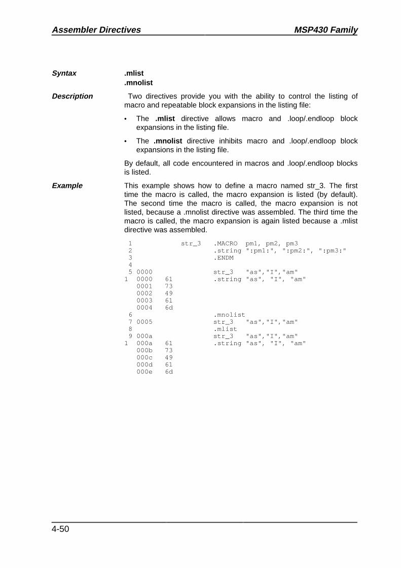
Assembler Directives MSP430 Family
4-50
Syntax .mlist.mnolist
Description Two directives provide you with the ability to control the listing ofmacro and repeatable block expansions in the listing file:
• The .mlist directive allows macro and .loop/.endloop blockexpansions in the listing file.
• The .mnolist directive inhibits macro and .loop/.endloop blockexpansions in the listing file.
By default, all code encountered in macros and .loop/.endloop blocksis listed.
Example This example shows how to define a macro named str_3. The firsttime the macro is called, the macro expansion is listed (by default).The second time the macro is called, the macro expansion is notlisted, because a .mnolist directive was assembled. The third time themacro is called, the macro expansion is again listed because a .mlistdirective was assembled.
1 str_3 .MACRO pm1, pm2, pm3 2 .string ":pm1:", ":pm2:", ":pm3:" 3 .ENDM 4 5 0000 str_3 "as","I","am"1 0000 61 .string "as", "I", "am" 0001 73 0002 49 0003 61 0004 6d 6 .mnolist 7 0005 str_3 "as","I","am" 8 .mlist 9 000a str_3 "as","I","am"1 000a 61 .string "as", "I", "am" 000b 73 000c 49 000d 61 000e 6d

MSP430 Family Assembler Directives
4-51
Syntax .newblock
Description The .newblock directive undefines any local labels currently defined. Alocal label, by nature, is temporary; the .newblock directive resets locallabels and terminates their scope.
A local label is a label in the form $n, where n is a single decimal digit.A local label, like other labels, points to an instruction byte. Unlikeother labels, local labels cannot be used in expressions; they can beused only as the operand in 10-bit jump instructions. Local labels arenot included in the symbol table.
After a local label has been defined and (perhaps) used, you shoulduse the .newblock directive to reset it. Note that the .text, .data, and.sect directives also reset local labels and that local labels that aredefined within an include file are not valid outside of the include file.
Example This example shows how the local label $1 is declared, reset, and thendeclared again.
1 0000 4c0d Label1: mov R12, R13 2 0002 2000 jnz $1 3 0004 433d mov #-1, r13 4 0006 9d04 $1 cmp R13, R4 5 .newblock ;undefine $1 6 0008 2000 jne $1 7 000a 531d inc R13 8 000c 5d0e $1 add R13, R14

Assembler Directives MSP430 Family
4-52
Syntax .option option list
Description The .option directive selects several options for the assembler outputlisting. The option list is a list of options separated by commas; eachoption selects a listing feature. Valid options include:
A Turns on all listing (overrides all other directives and options).
B Limits the listing of .byte directives to one line.
F Resets the B, M, W, and T options.
M Turns off macro expansions in the listing.
T Limits the listing of .string directives to one line.
W Limits the listing of .word directives to one line.
X Produces a symbol cross–reference listing.
Options are not case–sensitive.

MSP430 Family Assembler Directives
4-53
Example This example shows how to limit the listings of the .byte, .word, and.string directives to one line each.
1 ;**************************************** 2 ;* Limit the listing of .byte, .word, * 3 ;* .string directives to 1 line each * 4 ;**************************************** 5 .option B, W, T 6 0000 bd .byte -’C’, 0B0h, 5 7 0004 15aa .word 5546, 78h 8 0008 59 .string "YES" 9 ;****************************************10 ;* Reset the listing options *11 ;****************************************12 .option F13 000b bd .byte -’C’, 0B0h, 5 000c b0 000d 0514 000e 15aa .word 5546, 78h 0010 007815 0012 59 .string "YES" 0013 45 0014 5316 ;****************************************17 ;* Use The A option to ignore all *18 ;* other options and directives *19 ;****************************************20 .option A21 .nolist22 .option B, W, T23 0015 bd .byte -’C’, 0B0h, 5 0016 b0 0017 0524 0018 15aa .word 5546, 78h 001a 007825 001c 59 .string "YES" 001d 45 001e 5326 .list

Assembler Directives MSP430 Family
4-54
Syntax .page
Description The .page directive produces a page eject in the listing file. The .pagedirective is not printed in the source listing, but the line counter isincremented. Using the .page directive to divide the source listing intological divisions improves program readability.
Example This example shows how the .page directive causes the assembler tobegin a new page of the source listing.
Source file:
.title "**** Page Directive Example ****"; .; .; . .page
Listing file:
MSP TSS430 Macro Assembler Prototype Version 1.0 [Mar 22] Wed Aug 18 08:34:18 1993 Copyright (c) 1993 Texas Instruments Incorporated
**** Page Directive Example **** PAGE 1
2 ; . 3 ; . 4 ; .MSP TSS430 Macro Assembler Prototype Version 1.0 [Mar 22] Wed Aug 18 08:34:18 1993 Copyright (c) 1993 Texas Instruments Incorporated
**** Page Directive Example **** PAGE 2

MSP430 Family Assembler Directives
4-55
Syntax .sect "section name"[,address]
Description The .sect directive defines a named section that can be used like thedefault .text and .data sections. The .sect directive begins assemblingsource code into the named section.
• The section name identifies a section that the assemblerassembles code into. The name is significant to 8 characters andmust be enclosed in double quotes.
• The address is an optional parameter that specifies a 16–bitaddress. It can be used only the first time a .sect directive isspecified for a particular section. Normally, the SPC is set to 0 thefirst time a named section is assembled; you can use the addressparameter to assign an initial value to the SPC. This parameter hasno effect on the final address of the section; it simply makes thelisting easier to read.
Example This example shows how two special–purpose sections, Sym_Defsand Vars, are defined, and how code assembles into them.
1 ;************************************* 2 ;* Begin assembling into .text * 3 ;************************************* 4 0000 .text 5 0000 4b0c MOV R11, R12 6 0002 4d0e MOV R13, R14 7 8 ;************************************* 9 ;* Begin assembling into Sym_Defs *10 ;*************************************11 0000 .sect "Sym_Defs"12 0000 00aa X .word 0aah13 0002 50340005 ADD #5, R41415 ;*************************************16 ;* Begin assembling into Vars *17 ;*************************************18 4000 .sect "Vars", 4000h19 10 Word_Len .set 1620 08 Byte_Len .set 16 / 22122 ;*************************************23 ;* Resume assembling into .text *24 ;*************************************25 0004 .text26 0004 5034002a ADD #42, R427 0008 03 .byte 3,4 0009 0428 ;*************************************29 ;* Resume assembling into Vars *30 ;*************************************31 4000 .sect "Vars"32 4000 01 .field 1,233 4000 09 .field 2,2

Assembler Directives MSP430 Family
4-56
Syntax symbol .set valuesymbol .equ value
Description The .set and .equ directives equate a constant value to a symbol. Thesymbol can then be used in place of a value in assembly source. Thisallows you to equate meaningful names with constants and othervalues. The .set and .equ directives are identical and can be usedinterchangeably.
• The symbol must appear in the label field.
• The value must be a well–defined expression; that is, all symbolsin the expression must be previously defined in the current sourcemodule.
Undefined external symbols and symbols that are defined later in themodule cannot be used in the expression. If the expression isrelocatable, the symbol to which it is assigned is also relocatable.
The value of the expression appears in the object field of the listing.This value is not part of the actual object code and is not written to theoutput file.

MSP430 Family Assembler Directives
4-57
Example This example shows how symbols can be assigned with .set.
1 ;************************************* 2 ;* Equate symbol FP to register R11 * 3 ;* and use it instead of R11 * 4 ;************************************* 5 0b FP .set R11 6 0000 4b24 MOV @FP, R4 7 8 ;************************************* 9 ;* Set symbol count to an integer *10 ;* expression and use it as an *11 ;* immediate operand *12 ;*************************************13 35 count .equ 100/2+314 0002 40340035 MOV #count, R41516 ;*************************************17 ;* Set symbol symtab to relocatable *18 ;* expression *19 ;*************************************20 0006 000a label .word 1021 ’07 symtab .set label+122 0008 ’0007 .word symtab2324 ;*************************************25 ;* Set symbol nsyms to another *26 ;* symbol (count) and use it instead *27 ;* of count *28 ;*************************************29 35 nsyms .equ count30 000a 40340035 MOV #nsyms, R4

Assembler Directives MSP430 Family
4-58
Syntax .space size in bytes
Description The .space directive reserves size number of bytes in the currentsection and fills them with 0s. The section program counter isincremented to point to the byte following the reserved space.
When you use a label with the .space directive, it points to the firstbyte reserved.
Example This example shows how the .space directive reserves memory.
1 ;************************************ 2 ;* Begin assembling into .text * 3 ;************************************ 4 0000 .text 5 6 ;************************************ 7 ;* Reserve 15 bytes in .text * 8 ;************************************ 9 0000 .space 0fh10 0010 0100 .word 100h, 200h 0012 02001112 ;************************************13 ;* Begin assembling into .data *14 ;************************************15 0000 .data16 0000 2e .string ".data" 0001 64 0002 61 0003 74 0004 611718 ;************************************19 ;* Reserve 100 bytes in .data; *20 ;* Res_1 points to the first byte *21 ;************************************22 0005 Res_1 .space 10023 006a 000f .word 1524 006c "0005 .word Res_1

MSP430 Family Assembler Directives
4-59
Syntax .sslist
.ssnolist
Description Two directives enable you to control substitution symbol expansion inthe listing file:
• The .sslist directive allows substitution symbol expansion in thelisting file. The expanded line appears below the actual source line.
• The .ssnolist directive inhibits substitution symbol expansion inthe listing file.
By default, all substitution symbol expansion in the listing file isinhibited. The lines with the pound (#) character denote expandedsubstitution symbols.

Assembler Directives MSP430 Family
4-60
Example This example shows code that by default (.ssnolist directive) inhibitsthe listing of substitution symbol expansion, and it shows the .sslistdirective assembled, which tells the assembler to list substitutionsymbol code expansion.
1 0000 .bss x,1 2 0001 .bss y,1 3 4 ADD2 .macro pm1, pm2 5 mov pm1,R4 6 mov R4, R5 7 mov pm2, R4 8 add R5, R4 9 mov R4, pm2 10 .endm 11 12 .asg R11, FP 13 .asg R13, SSP 14 15 0000 4b0d mov FP, SSP 16 0002 add2 x, y1 0002 -40140000 mov x,R41 0006 4405 mov R4, R51 0008 -4014fff7 mov y, R41 000c 5504 add R5, R41 000e -4480fff1 mov R4, y 17 18 .sslist 19 20 0012 4b0d mov FP, SSP# mov R11, R13 21 0014 add2 x, y1 0014 -40140000 mov pm1,R4# mov x,R41 0018 4405 mov R4, R51 001a -4014ffe5 mov pm2, R4# mov y, R41 001e 5504 add R5, R41 0020 -4480ffdf mov R4, pm2# mov R4, y

MSP430 Family Assembler Directives
4-61
Syntax [ stag1 ] .struct [ expr1 ][ mem0 ] element [ expr2 ][ mem1 ] element [ expr2 ] . . . . . .[ memn ] .tag stag2 [,expr2] . . .[ memN ] element [ expr2 ][ size ] .endstruct
label .tag stag1
Description The .struct directive assigns symbolic offsets to the elements of a datastructure definition. This enables you to group similar data elementstogether and then let the assembler do the element offset calculation.This is similar to a C structure or a Pascal record. The .struct directivedoes not allocate any memory; it merely creates a symbolic templatethat can be used repeatedly.
The .tag directive gives structure characteristics to a label, simplifyingthe symbolic representation and providing the ability to definestructures that contain other structures. .tag does not allocate memory.The structure tag (stag) of a .tag directive must have been previouslydefined.
[ stag1 ] Is the structure’s tag. Its value is associated with thebeginning of the structure. If no stag is present, this tells theassembler to put the structure members in the global symboltable with their value being their absolute offset from the topof the structure.
[ expr1 ] Is an expression indicating the beginning offset of thestructure. Structures default to start at 0.
[ memn ] Is a label for a member of the structure. This label isabsolute and equates to the present offset from thebeginning of the structure.
element Is one of the following descriptors: .string, .byte, .word,.float, .double, .tag, and .field. All of these, except .tag, aretypical directives that initialize memory. Following a .structdirective, these directives describe the structure element’ssize. They do not allocate memory. A .tag directive is aspecial case because a stag must be specified (such asstag2 in the definition).
[ expr2 ] Is an expression for the number of elements described. Thisvalue defaults to 1.
[ size ] Is a label for the total size of the structure.

Assembler Directives MSP430 Family
4-62
Note: The Types of Directives That Can Appear in a .struct/.endstructSequence
The only directives that can appear in a .struct/.endstruct sequence are elementdescriptors, conditional assembly directives, and the .align and .even directives, whichalign the member offsets on byte resp. word boundaries. Note that empty structures areillegal.
Examples 1 0000 real_rec .struct ;stag 2 0000 nom .byte ;member1 = 0 3 0001 den .byte ;member2 = 1 4 0002 real_len .endstruct ;real_len = 2 5 6 0000 -4014ffff mov real+real_rec.den,R4 ;access 7 8 0000 .bss real,real_len ;allocate 9
10 0000 cplx_rec .struct ;stag11 0000 reali .tag real_rec ;member1 = 012 0002 imagi .tag real_rec ;member2 = 213 0004 cplx_len .endstruct ;cplx_len = 41415 complex .tag cplx_rec16 0002 .bss complex,cplx_len ;allocate1718 0004 -4014fffe mov complex.imagi.nom,R419 0008 -9014fff9 cmp complex.reali.den,R420
21 0000 .struct ;no stag puts members22 ;into global symbol table23 0000 x .byte ;create 3dim templates24 0001 y .byte25 0002 z .byte26 .endstruct27
28 0000 bit_rec .struct ;stag29 0000 stream .string 6430 0040 bit7 .field 731 0040 bit2 .field 232 0041 bit5 .field 533 0042 x_int .byte34 0043 bit_len .endstruct3536 bits .tag bit_rec37 0006 .bss bits,bit_len3839 000c -40140038 mov bits.bit7,R4 ;load field40 0010 f034007f and #7fh,R4 ;mask off garbage

MSP430 Family Assembler Directives
4-63
Syntax .text [address]
Description The .text directive tells the assembler to begin assembling into the.text section, which usually contains executable code. The sectionprogram counter is set to 0 if nothing has yet been assembled into the.text section. If code has already been assembled into the .textsection, the section program counter is restored to its previous value inthe section.
The address is an optional parameter that specifies a 16–bit address.It can be used only the first time a .text directive is specified. Normally,the section program counter is set to 0 the first time the .text section isassembled; you can use this parameter to assign an initial value to the.text section program counter. This parameter has no effect on thefinal address of the section; it simply makes the listing easier to read.
Note that the assembler assumes that .text is the default section.Therefore, at the beginning of an assembly, the assembler assemblescode into the .text section unless you specify one of the other sectionsdirectives (.data or .sect).
Example This example shows code assembled into the .text and .data sections.The .data section contains integer constants, and the .text sectioncontains character strings.
1 ;************************************** 2 ;* Begin assembling into .data * 3 ;************************************** 4 0000 .data 5 0000 05 .byte 5,6 0001 06 6 7 ;************************************** 8 ;* Begin assembling into .text * 9 ;**************************************10 7000 .text 7000h11 7000 01 .byte 112 7001 02 .byte 2, 3 7002 031314 ;**************************************15 ;* Resume assembling into .data *16 ;**************************************17 0002 .data18 0002 07 .byte 7,8 0003 081920 ;**************************************21 ;* Resume assembling into .text *22 ;**************************************23 7003 .text24 7003 04 .byte 4

Assembler Directives MSP430 Family
4-64
Syntax .title "string"
Description The .title directive supplies a title that is printed in the heading on eachlisting page. The source statement itself is not printed, but the linecounter is incremented. The string is a quote–enclosed title of up to 65characters. If you supply more than 65 characters, the assemblertruncates the string and issues a warning.
The assembler prints the title on the page that follows the directive andon subsequent pages until another .title directive is processed. If youwant a title on the first page of a listing, the first source statement mustcontain a .title directive.
Example This example shows how to print one title on the first page and adifferent title on succeeding pages.
Source file:
.title "** Integer Routines **"; .; .; . .title "** Floating Point Routines **" .page
Listing file:
MSP TSS430 Macro Assembler Prototype Version 1.0 [Mar 22] Wed Aug 18 11:01:02 1993 Copyright (c) 1993 Texas Instruments Incorporated
** Integer Routines ** PAGE 1
2 ; . 3 ; . 4 ; .MSP TSS430 Macro Assembler Prototype Version 1.0 [Mar 22] Wed Aug 18 11:01:02 1993 Copyright (c) 1993 Texas Instruments Incorporated
** Floating Point Routines ** PAGE 2

MSP430 Family Assembler Directives
4-65
Syntax symbol .usect "section name", size in bytes
Description The .usect directive reserves space for variables in an uninitialized,named section. This directive is similar to the .bss directive; bothsimply reserve space for data and have no contents. .usect definesadditional sections, however, that can be placed anywhere inmemory, independently of the .bss section.
• The symbol points to the first location reserved by this invocationof the .usect directive. The symbol corresponds to the name of thevariable that you’re reserving space for.
• The section name must be enclosed in double quotes; only the first8 characters are significant. This parameter names the uninitializedsection.
• The size is an expression that defines the number of bytes that arereserved in section name.
• The address is an optional parameter that specifies a 16–bitaddress. It can be used only the first time a .usect directive isspecified for a particular section. Normally, the SPC is set to 0 thefirst time a named section is assembled; you can use the addressparameter to assign an initial value to the SPC. This parameter hasno effect on the final address of the section.
Other sections directives (.text, .data, and .sect) end the currentsection and tell the assembler to begin assembling into anothersection. The .usect, .bss, .regpair, and .reg directives, however, do notaffect the current section. The assembler assembles the .usect, .bss,.regpair, and .reg directives and then resumes assembling into thecurrent section.
You can repeat the .usect directive to define more than one variable inthe specified section. Variables that can be located contiguously inmemory can be defined in the same section by using multiple .usectdirectives with the same section name.
Example This example shows how to use the .usect directive to define twouninitialized, named sections, var1 and var2. The symbol ptr points tothe first byte reserved in the var1 section. The symbol array points tothe first byte in a block of 100 bytes reserved in var1, and dflag pointsto the first byte in a block of 50 bytes in var1. The symbol vec points tothe first byte reserved in the var2 section.

Assembler Directives MSP430 Family
4-66
1 ;************************************ 2 ;* Assemble into .text * 3 ;************************************ 4 0000 .text 5 0000 40340003 mov #03h, R4 6 7 ;************************************ 8 ;* Reserve 1 byte in var1 * 9 ;************************************10 0000 ptr .usect "var1",11112 ;************************************13 ;* Reserve 100 more bytes in var1 *14 ;************************************15 0001 array .usect "var1",1001617 0004 50340037 add #37h, R4 ; still in .text1819 ;************************************20 ;* Reserve 50 more bytes in var1 *21 ;************************************22 0065 dflag .usect "var1",502324 0008 -4014005b mov dflag, R4; still in .text2526 ;************************************27 ;* Reserve 100 bytes in var2 *28 ;************************************29 0000 vec .usect "var2", 1003031 000c -90140000 cmp vec, R4 ; still in .text3233 ;************************************34 ;* Declare external .usect symbol *35 ;************************************36 .global array
100 bytes
100 bytes
50 bytes
1 byteptr
array
dflag
vecsection var1 section var2
100 bytes reserved in var2
151 bytes reserved in var1
Example 4.8: The .usect Directive

MSP430 Family Assembler Directives
4-67
Syntax .word value1 [, ... , valuen]
Description The .word directive places one or more 16–bit values into consecutivetwo–byte pairs in the current section.
The values can be either absolute or relocatable expressions. If anexpression is relocatable, the assembler generates a relocation entrythat refers to the appropriate symbol; the linker can then correctlypatch (relocate) the reference. This allows you to initialize memorywith pointers to variables or labels.
You can use as many values as fit on a single line. If you use a label, itpoints to the first word that is initialized.
Note that when you use .word in a .struct/.endstruct sequence, itdefines a member's size; it does not initialize memory.
Example This example shows how to use the .word directive to initialize words.The symbol WordX points to the first word that is reserved.
1 0000 0c80 Wordx: .word 3200, 1+’B’, -0afh, ’X’ 0002 0043 0004 ff51 0006 0058

Assembler Directives MSP430 Family
4-68

MSP430 Family Instruction Set Summary
5-1
Topics
5 Instruction Set Summary 5-3
5.1 Symbols and Abbreviations 5-4
5.2 Addressing Modes 5-5
5.3 Instruction Set Summary 5-6
5.4 Clock cycles, Length of Instruction 5-85.4.1 Format I Instructions 5-85.4.2 Format II Instructions 5-95.4.3 Format III Instructions 5-95.4.4 Miscellanous Instructions or Operators 5-9
Tables
Table Title Page5.1 Symbols and Abbreviations used in the Instruction Set Summary 5-4
5.2 Addressing Modes 5-5
5.3 MSP430 Family Instruction Set Summary 5-6
5.4 Format I Instructions 5-8
5.5 Format II Instructions 5-9
Notes
Title Page5.1 Addressing Modes 5-5
5.2 Emulated Instructions 5-7
5.3 Cycle Time of the DADD Instruction 5-8
5.4 Immediate mode in destination field 5-9

Instruction Set Summary MSP430 Family
5-2

MSP430 Family Instruction Set Summary
5-3
5 Instruction Set Summary
This chapter summarizes the MSP430 family instruction set.

Instruction Set Summary MSP430 Family
5-4
5.1 Symbols and Abbreviations
The following table lists the instruction set symbols and abbreviations used throughout therest of this chapter.
Symbol Definition Symbol Definition
src The source operand defined byAs and S-reg
dst The destination operand definedby Ad and D-reg
As The bits representing theaddressing mode used for thesource
Ad The bit representing theaddressing mode used for thedestination
S-reg The used Working Register forthe source src
D-reg The used Working Register forthe destination dst
R0 or PC Register 0 or Program Counter R1 or SP Register 1 or Stack Pointer
R2 orSR/CG1
Register 2 or StatusRegister/Constant Generator 1
R3 orCG2
Register 3 or ConstantGenerator 2
R4 toR15
Working Register,general purpose
Rn Working Register with n=4-15,general purpose
# Immediate Data @ Register indirect addressing
& Absolute address --> Data transfer direction
label 16-bit label TOS Top of Stack
C Carry Bit N Negative Bit
V Overflow Bit Z Zero Bit
.B The suffix .B at the instructionmemonic will result in a byteoperation
.W The suffix .W or no suffix at theinstruction memonic will result ina word operation
MSB Most significant Bit LSB Least significant Bit
Table 5.1: Symbols and Abbreviations used in the Instruction Set Summary

MSP430 Family Instruction Set Summary
5-5
5.2 Addressing Modes
All seven addressing modes for the source operand and all four addressing modes for thedestination operand can address the complete address space. The bit numbers show thecontents of the As resp. Ad mode bits.
As Ad Addressing Mode Syntax Description
00 0 Register Mode Rn Register contents are operand
01 1 Indexed Mode X(Rn) (Rn + X) points to the operand.X is stored in the next word
01 1 Symbolic Mode ADDR (PC + X) points to the operand.X is stored in the next word. IndexedMode X(PC) is used
01 1 Absolute Mode &ADDR The word following the instructioncontains the absolute address.
10 - Indirect RegisterMode
@Rn Rn is used as a pointer to the operand
11 - IndirectAutoincrement
@Rn+ Rn is used as a pointer to the operand.Rn is incremented afterwards
11 - Immediate Mode #N The word following the instructioncontains the immediate constant N.Indirect Autoincrement Mode @PC+ isused
Table 5.2: Addressing Modes
Note: Addressing Modes
The addressing modes using the PC as the working register use the normal effects of theaddressing modes. The special addressing modes are caused by the pointing of the PC tothe ROM word following the currently executed instruction.

Instruction Set Summary MSP430 Family
5-6
5.3 Instruction Set Summary
Status Bits
V N Z C* ADC(.B) dst dst + C → dst x x x x
ADD(.B) src,dst src + dst → dst x x x xADDC(.B) src,dst src + dst + C → dst x x x xAND(.B) src,dst src .and. dst → dst 0 x x xBIC(.B) src,dst .not.src .and. dst → dst - - - -BIS(.B) src,dst src .or. dst → dst - - - -BIT(.B) src,dst src .and. dst 0 x x x
* BR dst Branch to ....... - - - -CALL dst PC+2 → stack, dst → PC - - - -
* CLR(.B) dst Clear destination - - - -* CLRC Clear carry bit - - - 0* CLRN Clear negative bit - 0 - -* CLRZ Clear zero bit - - 0 -
CMP(.B) src,dst dst - src x x x x* DADC(.B) dst dst + C → dst (decimal) x x x x
DADD(.B) src,dst src + dst + C → dst (decimal) x x x x* DEC(.B) dst dst - 1 → dst x x x x* DECD(.B) dst dst - 2 → dst x x x x* DINT Disable interrupt - - - -* EINT Enable interrupt - - - -* INC(.B) dst Increment destination, dst +1 → dst x x x x* INCD(.B) dst Double-Increment destination, dst+2→dst x x x x* INV(.B) dst Invert destination x x x x
JC/JHS Label Jump to Label if Carry-bit is set - - - -JEQ/JZ Label Jump to Label if Zero-bit is set - - - -JGE Label Jump to Label if (N .XOR. V) = 0 - - - -JL Label Jump to Label if (N .XOR. V) = 1 - - - -JMP Label Jump to Label unconditionally - - - -JN Label Jump to Label if Negative-bit is set - - - -
Legend: 0 Status bit always cleared 1 Status bit always setx Status bit cleared or set on results - Status bit not affected* Emulated Instructions
Table 5.3: MPS430 Family Instruction Set Summary

MSP430 Family Instruction Set Summary
5-7
Status Bits
V N Z CJNC/JLO Label Jump to Label if Carry-bit is reset - - - -JNE/JNZ Label Jump to Label if Zero-bit is reset - - - -MOV(.B) src,dst src → dst - - - -
* NOP No operation - - - -* POP(.B) dst Item from stack, SP+2 → SP - - - -
PUSH(.B) src SP - 2 → SP, src → @SP - - - -RETI Return from interrupt x x x x
TOS → SR, SP + 2 → SPTOS → PC, SP + 2 → SZP
* RET Return from subroutine - - - -TOS → PC, SP + 2 → SP
* RLA(.B) dst Rotate left arithmetically x x x x* RLC(.B) dst Rotate left through carry x x x x
RRA(.B) dst MSB → MSB ....LSB → C 0 x x xRRC(.B) dst C → MSB .........LSB → C x x x x
* SBC(.B) dst Subtract carry from destination x x x x* SETC Set carry bit - - - 1* SETN Set negative bit - 1 - -* SETZ Set zero bit - - 1 -
SUB(.B) src,dst dst + .not.src + 1 → dst x x x xSUBC(.B) src,dst dst + .not.src + C → dst x x x xSWPB dst swap bytes - - - -SXT dst Bit7 → Bit8 ........ Bit15 0 x x x
* TST(.B) dst Test destination x x x xXOR(.B) src,dst src .xor. dst → dst x x x x
Legend: 0 The Status Bit is cleared 1 The Status Bit is setx The Status Bit is affected - The Status Bit is not affected* Emulated Instructions
Table 5.3: MPS430 Family Instruction Set Summary (Concluded)
Note: Emulated InstructionsAll marked instructions ( * ) are emulated instructions. The emulated instructions use coreinstructions combined with the architecture and implementation of the CPU for higher codeefficiency and faster execution.

Instruction Set Summary MSP430 Family
5-8
5.4 Clock cycles, Length of Instruction
The operating speed of the CPU is independent from individual instructions. It depends onthe instruction format and the addressing modes. The number of clock cycles refer to theinternal oscillator frequency.
5.4.1 Format I Instructions
Address Mode #of cycles Length of ExampleAs Ad instruction
00, Rn 0, Rm0,PC
12
11
MOV R5,R8BR R9
00, Rn 1, x(Rm)1, EDE
4 22
ADD R5,3(R6)XOR R8,EDE
1, &EDE 2 MOV R5,&EDE01, x(Rn)01, EDE01, &EDE
0, Rm 3 22
MOV 2(R5),R7AND EDE,R6MOV &EDE,R8
01, x(Rn)01, EDE
1, x(Rm)1, TONI
6 33
ADD 3(R4),6(R9)CMP EDE,TONI
01, &EDE 1, &TONI 3 MOV 2(R5),&TONIADD EDE,&TONI
10, @Rn 0, Rm 2 1 AND @R4,R510, @Rn 1, x(Rm)
1, EDE5 2
2XOR @R5,8(R6)MOV @R5,EDE
1, &EDE 2 XOR @R5,&EDE11, @Rn+
11, #N
0, Rm0, PC0, Rm0, PC
2322
1122
ADD @R5+,R6BR @R9+MOV #20,R9BR #2AEh
11, @Rn+11, #N
1, x(Rm)1, EDE
5 23
MOV @R9+,2(R4)ADD #33,EDE
11, @Rn+11, #N
1, &EDE 23
MOV @R9+,&EDEADD #33,&EDE
Table 5.4: Format I Instructions
Note: Cycle Time of the DADD Instruction
The DADD instruction needs 1 extra cycle.

MSP430 Family Instruction Set Summary
5-9
5.4.2 Format II Instructions
Address Mode #of cycles Length of ExampleA(s/d) RRC
RRASWPBSXT
PUSH/CALL
instruction[words]
00, Rn 1 3/4 1 SWPB R501, x(Rn)01, EDE
44
55
22
CALL 2(R7)PUSH EDE
10, @Rn 3 4 1 RRC @R9
11, @Rn+ see Note
11, #N33
4/54/5
12
SWPB @R10+CALL #81h
Table 5.5: Format II Instructions
Note: Immediate mode in destination field
Instructions should not use immediate mode in the destination field. This would result inunpredictable program operation.
5.4.3 Format III Instructions
Jxx - instructions need all the same #-of-cycles independent of a successfull Jump or not.
Clock Cycle: 2 Cycle.
Length of Instruction: 1 word.
5.4.4 Miscellanous Instructions or Operators
RETI Clock Cycle: 5 Cycle.
Length of instruction: 1 word.
Interrupt Clock Cycle: 6 Cycle.

Instruction Set Summary MSP430 Family
5-10

MSP430 Family Macro Language
6-1
Topics
6 Macro Language 6-3
6.1 Using Macros 6-4
6.2 Defining Macros 6-5
6.3 Macro Parameters/Substitution Symbols 6-7
6.4 Macro Libraries 6-15
6.5 Using Conditional Assembly in Macros 6-16
6.6 Using Labels in Macros 6-18
6.7 Producing Messages in Macros 6-20
6.8 Formatting the Output Listing 6-21
6.9 Using Recursive and Nested Macros 6-22
6.10 Macro Directives Summary 6-24
Examples
Ex. Title Page6.1 Macro Definition, Call, and Expansion 6-6
6.2 Calling a Macro With Varying Numbers of Arguments 6-8
6.3 Using the .asg Directive 6-8
6.4 Using the .eval Directive 6-9
6.5 Using Built–In Substitution Symbol Functions 6-10
6.6 Recursive Substitution 6-11
6.7 Using the Forced Substitution Operator 6-12
6.8 Using Subscripted Substitution Symbols to Redefine an Instruction 6-13
6.9 Using Subscripted Substitution Symbols to Find Substrings 6-13
6.10 The .loop/.break/.endloop Directives 6-17
6.11 Nested Conditional Assembly Directives 6-17
6.12 Unique Labels in a Macro 6-19
6.13 Producing Messages in a Macro 6-20
6.14 Using Nested Macros 6-22
6.15 Using Recursive Macros 6-23

Macro Language MSP430 Family
6-2

MSP430 Family Macro Language
6-3
6 Macro Language
The assembler supports a macro language that enables you to create your own “instruc-tions." This is especially useful when a program executes a particular task several times. Themacro language enables you to:
• Define your own macros and redefine existing macros.
• Simplify long or complicated assembly code.
• Access macro libraries created with the archiver.
• Define conditional and repeatable blocks within a macro.
• Manipulate strings within a macro.
• Control expansion listing.

Macro Language MSP430 Family
6-4
6.1 Using Macros
Programs often contain routines that are executed several times. Instead of repeating thesource statements for a routine, you can define the routine as a macro, then call the macroin the places where you would normally repeat the routine. This simplifies and shortens yoursource program.
If you want to call a macro several times, but with different data each time, you can assignparameters to a macro. This enables you to pass different information to the macro eachtime you call it. The macro language supports a special symbol called a substitutionsymbol, which is used for macro parameters. In this chapter, we use the terms macroparameters and substitution symbols interchangeably.
Using a macro is a three–step process:
Step 1: Define the macro. You must define macros before you can use them in yourprogram. There are two methods for defining macros:
• Macros can be defined at the beginning of a source file or in an .include/.copyfile.
• Macros can also be defined in a macro library. A macro library is a collection offiles in archive format, created by the archiver. Each member of the archive file(macro library) may contain one macro definition corresponding to the membername. You can access a macro library by using the .mlib directive.
Step 2: Call the macro. After you have defined a macro, you can call it by using the macroname as an opcode in the source program. This is referred to as a macro call.
Step 3: Expand the macro. The assembler expands your macros when the source programcalls them. During expansion, the assembler passes arguments by variable to themacro parameters, replaces the macro call statement with the macro definition, thenassembles the source code. By default, the macro expansions are printed in thelisting file. You can turn off expansion listing by using the .mnolist directive.
When the assembler encounters a macro definition, it places the macro name in the opcodetable. This redefines any previously defined macro, library entry, directive, or instructionmnemonic that has the same name as the encountered macro. This allows you to expandthe functions of directives and instructions, as well as add new instructions.

MSP430 Family Macro Language
6-5
6.2 Defining Macros
You can define a macro anywhere in your program, but you must define the macro beforeyou can use it. Macros can be defined at the beginning of a source file or in an .include/.copyfile; they can also be defined in a macro library.
The contents of a macro definition must be contained in the same file. Macro definitions canbe nested, and they can call other macros.
A macro definition is a series of source statements in the following format:
macname .macro [parameter1] [,parameter2] ... [,parametern]
model statements or macro directives
[.mexit]
.endm
macname names the macro. You must place the name in the source statement’slabel field. Only the first 32 characters of a macro name are significant.The assembler places the macro name in the internal opcode table,replacing any instruction or previous macro definition with the samename.
.macro is a directive that identifies the source statement as the first line of amacro definition. You must place .macro in the opcode field.
[parameters] are optional substitution symbols that appear as operands for the.macro directive.
model statements are instructions or assembler directives that are executed each timethe macro is called.
macro directives are used to control macro expansion.
[.mexit] functions as a “goto .endm". The .mexit directive is useful when errortesting confirms that macro expansion will fail.
.endm terminates the macro definition.

Macro Language MSP430 Family
6-6
Macro definition: The following code defines a macro, add3, with 3 parameters:
1 ;* add3 arg1, arg2, arg3 2 ;* arg3 = arg1 + arg2 + arg3 3 4 add3 .macro arg1, arg2, arg3 5 6 mov arg1, R4 7 mov R4, R5 8 mov arg2, R4 9 add R4, R5 10 mov arg3, R4 11 add R5, R4 12 mov R4, arg3 13 .endm
Macro Call: The following code calls the add3 macro with 3 arguments
14 15 0000 add3 x, y ,z
Macro Expansion: The following code shows the substitution of the macro definition for themacro call. The assembler passes the arguments (supplied in the macro call) by variableto the parameters (substitution symbols).
11 0000 -40140000 mov x, R41 0004 4405 mov R4, R51 0006 -4014fff9 mov y, R41 000a 5405 add R4, R51 000c -4014fff4 mov z, R41 0010 5504 add R5, R41 0012 -4480ffee mov R4, z
16 17 18 ;* Reserve space for vars 19 0000 .bss x,1 20 0001 .bss y,1 21 0002 .bss z,1
Example 6.1: Macro Definition, Call, and Expansion
If you want to include comments with your macro definition but don’t want those commentsto appear in the macro expansion, precede your comments with an exclamation point. If youdo want your comments to appear in the macro expansion, use an asterisk or semicolon inplace of the exclamation point.

MSP430 Family Macro Language
6-7
6.3 Macro Parameters/Substitution Symbols
If you want to call a macro several times, but with different data each time, you can assignparameters to the macro. The macro language supports a special symbol, called asubstitution symbol, which is used for macro parameters.
Substitution Symbols
Macro parameters are substitution symbols. Substitution symbols are symbols that representa character string. Besides being used as macro parameters, these symbols can also beused outside of macros to equate a character string to a symbol name.
Valid substitution symbols may be 32 characters long and must begin with a letter. Theremainder of the symbol can be a combination of alphanumeric characters, underscores,and dollar signs.
Substitution symbols used as macro parameters are local to the macro they are defined in.You can define up to 32 local substitution symbols (including substitution symbols definedwith the .var directive) per macro.
During macro expansion, the assembler passes arguments by variable to the macroparameters. The character–string equivalent of each argument is assigned to thecorresponding parameter. Parameters without corresponding arguments are set to the nullstring. If the number of arguments exceeds the number of parameters, the last parameter isassigned the character–string equivalent of all remaining arguments.
If you pass a list of arguments to one parameter, or if you pass a comma or semicolon to aparameter, you must surround the arguments with quotation marks.
At assembly time, the assembler first replaces the substitution symbol with its correspondingcharacter string, then translates the source code into object code.

Macro Language MSP430 Family
6-8
Macro Definition
Parms .macro a,b,c; a = :a:; b = :b:; c = :c: .endm
Calling the Macro, Parms
Parms 100,label Parms 100,label,x,y; a = 100 ; a = 100; b = label ; b = label; c = " " ; c = x,y
Parms 100,x Parms "100,200,300",x,y; a = 100 ; a = 100,200,300; b = " " ; b = x; c = x ; c = y
Parms """string""",x,y; a = "string"; b = x; c = y
Example 6.2: Calling a Macro With Varying Numbers of Arguments
Directives That Define Substitution Symbols
You can manipulate substitution symbols with the .asg and .eval directives.
• The .asg directive assigns a character string to a substitution symbol.
The syntax of the .asg directive is:
.asg [“] character string ["], substitution symbol
The quotation marks are optional. If there are no quotation marks, the assembler readscharacters up to the first comma and removes leading and trailing blanks. In either case,a character string is read and assigned to the substitution symbol.
The example shows character strings being assigned to substitution symbols.
.asg R13,FP ; frame pointer .asg @ ,Ind ; indirect addressing .asg """string""",strng ; string .asg "a,b,c",parms ; parameters mov Ind(FP),R4 ; mov @(R13),R4
Example 6.3: Using the .asg Directive

MSP430 Family Macro Language
6-9
• The .eval directive performs arithmetic on numeric substitution symbols.
The syntax of the .eval directive is:
.eval well–defined expression, substitution symbol
The .eval directive evaluates the expression and assigns the string value of the result tothe substitution symbol. If the expression is not well defined, the assembler generates anerror and assigns the null string to the symbol.
The example shows arithmetic being performed on substitution symbols.
.asg 1, counter .loop 100 .word counter .eval counter+1, counter .endloop
Example 6.4: Using the .eval Directive
In the example, the .asg directive could be replaced with the .eval directive (.eval 1, counter)without changing the output. In simple cases like this, you can use .eval and .asginterchangeably. If you want to calculate a value from an expression, however, you must usethe .eval directive.
The .asg directive only assigns a character string to a substitution symbol, while the .evaldirective evaluates an expression and then assigns the character string equivalent to asubstitution symbol.
Built-In Substitution Symbol Functions
The following built–in substitution symbol functions enable you to make decisions based onthe string value of substitution symbols. These functions always return a value, and they canbe used in expressions. Built–in substitution symbol functions are especially useful inconditional assembly expressions. Parameters to these functions are substitution symbols orcharacter–string constants.
In the following function definitions, a and b are parameters that represent substitutionsymbols or character string constants. The term string, used below, refers to the string valueof the parameter.

Macro Language MSP430 Family
6-10
Function Return Value
$symlen(a) length of string a
$symcmp(a,b) < 0 if a < b 0 if a = b > 0 if a > b
$firstch(a,ch) index of the first occurrence of character constant ch in string a
$lastch(a,ch) index of the last occurrence of character constant ch in string a
$isdefed(a) 1 if string a is defined in the symbol table 0 if string a is not defined in the symbol table
$ismember(a,b) top member of list b is assigned to string a0 if b is a null string
$iscons(a) 1 if string a is a binary constant2 if string a is an octal constant3 if string a is a hexadecimal constant4 if string a is a character constant5 if string a is a decimal constant
$isname(a) 1 if string a is a valid symbol name0 if string a is not a valid symbol name
$isreg(a) 1 if string a is a valid predefined register name0 if string a is not a valid predefined register name
.asg Label, x ; x = label .if ($symcmp(x,"Label") = 0) ; evaluates to true cmp x,R4 .endif .asg "L1,L2,L3", list ; list = L1,L2,L3 .if ($ismember(x, list)) ; x = L1 list = L2,L3 cmp x,R4 .endif
Example 6.5: Using Built–In Substitution Symbol Functions

MSP430 Family Macro Language
6-11
Recursive Substitution Symbols
When the assembler encounters a substitution symbol, it attempts to substitute thecorresponding character string. If that string is also a substitution symbol, the assemblerperforms substitution again. The assembler continues doing this until it encounters a tokenthat is not a substitution symbol or until it encounters a substitution symbol that it has alreadyencountered during this evaluation.
In the example, the y is substituted for x; z is substituted for y; and x is substituted for z. Theassembler recognizes this as infinite recursion and ceases substitution.
.asg "x",z ; declare z and assign z = "x" .asg "z",y ; declare y and assign y = "z" .asg "y",x ; declare x and assign x = "y" cmp x, R4
;* cmp x, R4 ; recursive expansion
Example 6.6: Recursive Substitution
Forcing Substitutions
In some cases, substitution symbols are not recognizable to the assembler. The forcedsubstitution operator, which is a set of colons, enables you to force the substitution of asymbol’s character string. Simply surround a symbol with colons to force the substitution. Donot include any spaces between the colons and the symbol.
The syntax for the forced substitution operator is:
:symbol:
The assembler expands substitution symbols surrounded by colons before it expands anyother substitution symbols.
You can use the forced substitution operator only inside of macros, and you cannot nest aforced substitution operator within another forced substitution operator.

Macro Language MSP430 Family
6-12
force .macro x .asg 0, x .loop 8 ; loop/.endloop are discussed;* in Section 4.0AUX:x: .equ x ; The x in AUXx would not be;* recognizable as a substituion;* symbol by the assembler .eval x+1, x .endloop .endm
force ;macro call
This would generate the following source code:
AUX0 .equ 0 AUX1 .equ 1 . . AUx7 .equ 7
Example 6.7: Using the Forced Substitution Operator
Accessing Individual Characters of Subscripted Substitution Symbols
In a macro, you can access the individual characters (substrings) of a substitution symbolwith subscripted substitution symbols. You must use the forced substitution operator forclarity.
You can access substrings in two ways:
• :symbol (well–defined expression):
This method of subscripting evaluates to a character string with one character.
• :symbol (well–defined expression1, well–defined expression2):
In this method, expression1 represents the substring’s starting position, and expression2represents the substring’s length. You can specify exactly where to begin subscriptingand the exact length of the resulting character string. The index of substring charactersbegins with 1, not 0.
The next two examples show built–in substitution symbol functions used with subscriptedsubstitution symbols.

MSP430 Family Macro Language
6-13
In the first example, subscripted substitution symbols redefine the pop instruction so that ithandles indirect addressing.
popx macro x .var tmp,len .asg :x(1):,tmp .if $symcmp(tmp,"@") = 0 .eval $symlen(x),len .asg :x(2,len):,tmp .if $isreg(tmp) = 1 pop 0(tmp) .else .emsg "Bad Register Name" .endif .else .emsg "Bad Operand" .endif .endm
popx @R4 ; macro call
Example 6.8: Using Subscripted Substitution Symbols to Redefine an Instruction
In the second example, the subscripted substitution symbol is used to find a substring strg1beginning at position start in the string strg2. The position of the substring strg1 is assignedto the substitution symbol pos.
substr .macro start,strg1,strg2,pos .var len1,len2,i,tmp .if $symlen(start) = 0 .eval 1,start .endif .eval 0,pos .eval start,i .eval $symlen(strg1),len1 .eval $symlen(strg2),len2 .loop .break i = (len2-len1+1) .asg ":strg2(i,len1):",tmp .if $symcmp(strg1,tmp) = 0 .eval i,pos .break .else .eval i+1,i .endif .endloop .endm
.asg 0,pos .asg "ar1 ar2 ar3 ar4",regs substr 1,"ar2",regs,pos .word pos
Example 6.9: Using Subscripted Substitution Symbols to Find Substrings

Macro Language MSP430 Family
6-14
Substitution Symbols as Local Variables in Macros
If you want to use substitution symbols as local variables within a macro, you can use the.var directive to define up to 32 local macro substitution symbols (including parameters) permacro. The .var directive creates temporary substitution symbols with the initial value of thenull string. These symbols are not passed in as parameters, and, after expansion, thesesymbols are lost.
.var sym1 [,sym2] ... [,symn]
The .var directive is used in the last two examples.

MSP430 Family Macro Language
6-15
6.4 Macro Libraries
One of the ways you can define macros is in a macro library. A macro library is a collectionof files that contain macro definitions. You must use the archiver to collect these files, ormembers, into a single file (called an archive). Each member of a macro library contains onemacro definition. The files in a macro library must be unassembled source files. The macroname and the member name must be the same, and the macro filename’s extension mustbe .asm. For example:
Macro Name Filename in Macro Library
simple simple.asm
add3 add3.asm
You can access the macro library by using the .mlib assembler directive.
.mlib macro library filename
When the assembler encounters an .mlib directive, it opens the library and creates a table ofits contents. The assembler enters the names of the individual members within the libraryinto the opcode tables as library entries; this redefines any existing opcodes or macros thathave the same name. If one of these macros is called, the assembler extracts the entry fromthe library and loads it into the macro table. The assembler expands the library entry in thesame manner as other macros. You can control the listing of library entry expansions withthe .mlist directive. Only macros that are actually called from the library are extracted, andthey are extracted only once.
You can create a macro library with the archiver by simply including the desired files in anarchive. A macro library is no different from any other archive, except that the assemblerexpects the macro library to contain macro definitions. The assembler expects only macrodefinitions in a macro library; putting object code or miscellaneous source files into the librarymay produce undesirable results.

Macro Language MSP430 Family
6-16
6.5 Using Conditional Assembly in Macros
The conditional assembly directives are .if/.elseif/.else/.endif and .loop/.break/.endloop.They can be nested within each other up to 32 levels deep. The format of a conditional blockis:
.if well–defined expression
code block to execute when the .if expression is true (nonzero)
[.elseif well–defined expression]
code block to execute when the .elseif expression is true (nonzero)
[.else]
code block to execute when the .elseif expression is false (zero)
.endif
The .elseif and .else directives are optional, and they can be used more than once within aconditional assembly code block. When they are omitted, and when the .if expression is false(zero), the assembler continues to the code following the .endif directive.
The .loop/.break/.endloop directives enable you to assemble a code block repeatedly. Theformat of a repeatable block is:
.loop [well–defined expression]
code block to repeatedly assemble
[.break [well–defined expression]]
continue to repeatedly assemble when the .break expression is false (zero)
.endloop
code block to execute when the .break expression is true (nonzero) or when the.break expression is omitted and the loop count equals expression.
The .loop directive’s optional expression evaluates to the loop count. If the expression isomitted, the loop count defaults to 1024, unless the assembler encounters a .break directive.
The .break directive and its expression are optional. If the expression evaluates to false, theloop continues. The assembler breaks the loop when the .break expression evaluates to trueor when the .break expression is omitted and the loop count equals expression. When theloop is broken, the assembler continues with the code after the .endloop directive.
The next three examples show the .loop/.break/.endloop directives, properly nested con-ditional assembly directives, and built–in substitution symbol functions used in a conditionalassembly code block.

MSP430 Family Macro Language
6-17
.asg 1,x .loop
.break (x==10) ; If x==10, quit loop/break with expression
.eval x+1,x .endloop
Example 6.10: The .loop/.break/.endloop Directives
.asg 1,x .loop
.if (x==10) ; If x==10, quit loop .break ; force break .endif
.eval x+1,x .endloop
Example 6.11: Nested Conditional Assembly Directives

Macro Language MSP430 Family
6-18
6.6 Using Labels in Macros
All labels in an assembly language program must be unique. This includes labels in macros.If a macro is expanded more than once, its labels are defined more than once. Defining alabel more than once is illegal. The macro language provides a method of defining labels inmacros so that the labels are unique. Simply follow the label with a question mark, and theassembler will replace the question mark with a period followed by a unique number. Whenthe macro is expanded, you will not see the unique number in the listing file. Your label willappear with the question mark as it did in the macro definition. The syntax for a unique labelis:
label?

MSP430 Family Macro Language
6-19
1 min .macro x,y 2 mov x, R4 3 cmp y, r4 4 jl m1? 5 mov y, R4 6 m1? 7 .endm 8 9 10 11 0000 .bss var1 12 0001 .bss var2 13 0002 .bss var3 14 15 0000 min var1, var21 0000 -40140000 mov var1, R41 0004 -9014fffb cmp var2, r41 0008 ’3802 jl m1?1 000a -4014fff5 mov var2, R41 000e m1? 16 17 000e min var2, var31 000e -4014fff1 mov var2, R41 0012 -9014ffee cmp var3, r41 0016 ’3802 jl m1?1 0018 -4014ffe8 mov var3, R41 001c m1? 18
LABEL VALUE DEFN REF
m1.1 000e ’ 15 15m1.2 001c ’ 17 17var1 0000 - 11 15var2 0001 - 12 15 15 17var3 0002 - 13 17 17
Example 6.12: Unique Labels in a Macro
The maximum label length is shortened to allow for the unique suffix. For example, if themacro is expanded fewer than 10 times, the maximum label length is 30 characters. If themacro is expanded from 10 to 999 times, the maximum label length is 29. The label with itsunique suffix is shown in the cross–listing file.

Macro Language MSP430 Family
6-20
6.7 Producing Messages in Macros
The macro language supports three directives that enable you to define your own assembly–time error and warning messages. These directives are especially useful when you want tocreate messages specific to your needs. The last line of the listing file shows the error andwarning counts. These counts alert you to problems in your code and are especially usefulduring debugging.
.emsg sends error messages to the listing file. The .emsg directive generateserrors in the same way the assembler does, incrementing the error countand preventing the assembler from producing an object file.
.wmsg sends warning messages to the listing file. The .wmsg directive functions inthe same manner as the .emsg directive but increments the warning countand does not prevent the generation of an object file.
.mmsg sends warnings or assembly–time messages to the listing file. The .mmsgdirective functions in the same manner as the .emsg directive but does notset the error count or prevent the generation of an object file.
Macro comments are comments that appear in the definition of the macro but do not showup in the expansion of the macro. An exclamation point in column 1 identifies a macrocomment. If you want your comments to appear in the macro expansion, precede yourcomment with an asterisk or semicolon.
The example shows user messages in macros and macro comments that will not appear inthe macro expansion.
TEST .MACRO x,y;; This macro checks for the correct number of parameters.; The macro generates an error message if x an y are not present.; .if ($symlen(x) == 0|$symlen(y) == 0)) ; Test for ; proper input .emsg "ERROR - missing parameter in call to TEST" .mexit .else . . .endif .if . . .endif .endm
1 error, no warnings
Example 6.13: Producing Messages in a Macro

MSP430 Family Macro Language
6-21
6.8 Formatting the Output Listing
Macros, substitution symbols, and conditional assembly directives may hide information. Youmay need to see this hidden information, so the macro language supports an expandedlisting capability.
By default, the assembler shows macro expansions and false conditional blocks in the listoutput file. You may want to turn this listing off or on within your listing file. The assemblerprovides three sets of directives that enable you to control the listing of this information.
• Macro and Loop Expansion Listing
.mlist expands macros and .loop/.endloop blocks. The.mlist directive prints to thelisting all code encountered in those blocks. By default, the assemblerbehaves as if you had used .mlist.
.mnolist suppresses the listing expansion of macros and .loop/.endloop blocks.
• False Conditional Block Listing
.fclist causes the assembler to print to the listing file all false conditional blocksthat do not generate code. Conditional blocks appear in the listing exactlyas they appear in the source code. By default, the assembler behaves as ifyou had used .fclist.
.fcnolist suppresses the listing of false conditional blocks. Only the code inconditional blocks that actually assembles appears in the listing. The .if,.elsif, .else, and .endif directives do not appear in the listing.
• Substitution Symbol Expansion Listing
.sslist expands substitution symbols in the listing. This is useful for debugging theexpansion of substitution symbols. The expanded line appears below theactual source line.
.ssnolist turns off substitution symbol expansion in the listing. By default, theassembler behaves as if you had used .ssnolist.

Macro Language MSP430 Family
6-22
6.9 Using Recursive and Nested Macros
The macro language supports recursive and nested macro calls. This means that you cancall other macros from inside a macro definition. When you use nested macros, you can calldifferent macros from your macro definition. You can nest macros up to 32 levels deep.When you use recursive macros, you call a macro from its own definition (the macro callsitself).
When you create recursive or nested macros, you should pay close attention to thearguments that you pass to macro parameters because the assembler uses dynamicscoping for parameters. This means that the called macro uses the environment of themacro from which it was called.
The following example shows nested macros. Note that the y in the in_block macro hidesthe y in the out_block macro. The x and z from the out_block macro, however, areaccessible to the in_block macro.
in_block .macro y,a . ; visible parameters are y,a and . ; x,z from the calling macro .endm
out_block .macro x,y,z . ; visible parameters are x,y,z . in_block x,y ; macro call with x and y as ; arguments . . .endm out_block ; macro call
Example 6.14: Using Nested Macros

MSP430 Family Macro Language
6-23
The next example shows recursive macros. The fact macro produces assembly codenecessary to calculate the factorial of n where n is an immediate value. The result is placedin the A register. The fact macro accomplishes this by calling fact1, which calls itselfrecursively.
.fcnolist
fact1 .macro n
.if n == 1 mov #globcnt, R4 ; leave answer in R4 reg.
.else .eval n-1, temp ; compute decrement of n .eval globcnt*temp, globcnt ; multiply to get new result fact1 temp ; recursive call
.endif .endm
fact .macro n
.if ! $iscons(n) ; type check input .emsg "Parm not a constant"
.elseif n < 1 ; type check input mov #0, R4
.else .var temp .asg n, globcnt
fact1 n ; perform recursive procedute
.endif .endm
Example 6.15: Using Recursive Macros

Macro Language MSP430 Family
6-24
6.10 Macro Directives Summary
Creating Macros
Mnemonic and Syntax Description
macname .macro[parameter1]...[parametern]
Define macro
.mlib filename Identify library containing macro definitions
.mexit Go to .endm
.endm End macro definition
Manipulating Substitution Symbols
Mnemonic and Syntax Description
.asg [“]character string["], substitutionsymbol
Assign character string to substitutionsymbol
.eval well–defined expression, substitutionsymbol
Perform arithmetic on numeric substitutionsymbols
.var substitution symbol1...[substitutionsymboln]
Define local macro symbols
Conditional Assembly
Mnemonic and Syntax Description
.if well–defined expression Begin conditional assembly
.elseif well–defined expression Optional conditional assembly block
.else Optional conditional assembly block
.endif End conditional assembly
.loop [well–defined expression] Begin repeatable block assembly
.break [well–defined expression] Optional repeatable block assembly
.endloop End repeatable block assembly

MSP430 Family Macro Language
6-25
Producing Assembly–Time Messages
Mnemonic and Syntax Description
.emsg Send error message to standard output
.wmsg Send warning message to standard output
.mmsg Send assembly–time message to standardoutput
Formatting the Listing
Mnemonic and Syntax Description
.fclist Allow false conditional code block listing(default)
.fcnolist Inhibit false conditional code block listing
.mlist Allow macro listings (default)
.mnolist Inhibit macro listings
.sslist Allow expanded substitution symbol listing
.ssnolist Inhibit expanded substitution symbol listing(default)

Macro Language MSP430 Family
6-26

MSP430 Family Archiver Description
7-1
Topics
7 Archiver Description 7-3
7.1 Archiver Development Flow 7-4
7.2 Invoking the Archiver 7-5
7.3 Archiver Examples 7-7
Figures
Fig. Title Page7.1 Archiver Development Flow 7-4
Notes
Note Title Page7.1 Naming Library Members 7-6

Archiver Description MSP430 Family
7-2

MSP430 Family Archiver Description
7-3
7 Archiver Description
The MSP430 family archiver lets you combine several individual files into a single file calledan archive or a library. Each file within the archive is called a member. Once you havecreated an archive, you can use the archiver to add more files to the library, delete orreplace existing members, or extract members.
You can build libraries out of any type of files. Both the assembler and the linker acceptarchive libraries as input; the assembler can use libraries that contain individual source files,and the linker can use libraries that contain individual object files.
One of the most useful applications of the archiver is to build a library of object modules. Forexample, you could write several arithmetic routines, assemble them, and then use thearchiver to collect the object files into a single, logical group. You can then specify an objectlibrary as linker input. The linker will search through the library and include any members thatresolve external references.
You can also use the archiver to build macro libraries. You can create several separatesource files, each of which contains a single macro, and then use the archiver to collectthese macros into a single, functional group. The .mlib assembler directive lets you specifythe name of a macro library to the assembler; during the assembly process, the assemblerwill search the specified library for the macros that you call.

Archiver Description MSP430 Family
7-4
7.1 Archiver Development Flow
The figure shows the archiver’s role in the assembly language development process. Boththe assembler and the linker accept libraries as input.
Assembler Source
Assembler
COFF ObjectFiles
Linker
ExecutableCOFF Objekt
Files
MacroSource Files
Archiver
Macro Library
ObjectFormat
Converter
Archiver
Library ofObject Files
EPROMProgrammer
AbsoluteLister
MSP430SoftwareSimulator
EvaluationModule
In-CircuitEmulator
Figure 7.1: Archiver Development Flow

MSP430 Family Archiver Description
7-5
7.2 Invoking the Archiver
To invoke the archiver, enter:
ar430 [-]command[option] libname [filename1 ... filenamen]
ar430 is the command that invokes the archiver.
libname names an archive library. If you don’t specify an extension for libname, thearchiver uses the default extension .lib.
filename names individual member files that are associated with the library. If you don’tspecify an extension for a filename, the archiver uses the default extension .obj.
command tells the archiver how to manipulate the members in the library. A command canbe preceded by an optional hyphen. You must use one of the followingcommands when you invoke the archiver, but you can use only one commandper invocation. These are valid archiver commands:
-a adds the specified files to the library. Note that this command does notreplace an existing member that has the same name as an added file; itsimply appends new members to the end of the archive. It is possible tohave several members with the same name in an archive. If you want toreplace existing members, use the r command.
-d deletes the specified members from the library.
-r replaces the specified members in the library. If you don’t specify anyfilenames, the archiver replaces the library members with files of thesame name in the current directory. If the specified file is not found in thelibrary, the archiver adds it instead of replacing it.
-t prints a table of contents of the library. If you specify filenames, onlythose files are listed. If you don’t specify any filenames, the archiver listsall the members in the specified library.
-x extracts the specified files. If you don’t specify any member names, thearchiver extracts all the members in the library. When the archiverextracts a member, it simply copies the member into the currentdirectory; it doesn’t remove it from the library.
In addition to one of the commands, you can specify the following options:
-e tells the archiver not to use the default extension .obj for member names.This allows the use of filenames without extensions.
-q (quiet) suppresses the banner and status messages.
-s prints a list of the global symbols that are defined in the library. (Thisoption is valid only with the -a, -r, and -d commands.)
-v (verbose) provides a file–by–file description of the creation of a newlibrary from an old library and its constituent members.

Archiver Description MSP430 Family
7-6
Note: Naming Library Members
It is possible (but not desirable) for a library to contain several members with the samename. If you attempt to delete, replace, or extract a member, and the library containsmore than one member with the specified name, the archiver deletes, replaces, or extractsthe first member with that name.

MSP430 Family Archiver Description
7-7
7.3 Archiver Examples
Here are some examples of using the archiver.
• Example 1
This example creates a library called function.lib that contains the files sine.obj, cos.obj,and flt.obj.
ar430 -a function sine cos fltMSP430 Archiver Version 1.00Copyright (c) 1994 Texas Instruments Incorporated
==> new archive ’function.lib’==> building archive ’function.lib’
Because these examples use the default extensions (.lib for the library and .obj for themembers), it is not necessary to specify them.
• Example 2
You can print a table of contents of function.lib with the -t option:
ar430 -t functionMSP430 Archiver Version 1.00Copyright (c) 1994 Texas Instruments Incorporated FILE NAME SIZE DATE----------------- ----- ----------------------- sine.obj 248 Mon Feb 14 01:25:44 1994 cos.obj 248 Mon Feb 14 01:25:44 1994 flt.obj 248 Mon Feb 14 01:25:44 1994
• Example 3
You can explicitly specify extensions if you don’t want the archiver to use the defaultextensions; for example:
ar430 -av function.fn sine.asm cos.asm flt.asmMSP430 Archiver Version 1.00Copyright (c) 1994 Texas Instruments Incorporated ==> add ’sine.asm’
==> add ’cos.asm’==> add ’flt.asm’==> building archive ’function.fn’
This creates a library called function.fn that contains the files sine.asm, cos.asm, andflt.asm. (-v is the verbose option.)
• Example 4
If you want to add new members to the library, specify
ar430 -as function tan.obj arctan.obj area.objMSP430 Archiver Version 1.00Copyright (c) 1994 Texas Instruments Incorporated
==> symbol defined: ’R2D2’==> symbol defined: ’Christmas’==> building archive ’function.lib’
Because this example doesn’t specify an extension for the libname, the archiver adds thefiles to the library called function.lib. If function.lib didn’t exist, the archiver would create it.(The -s option tells the archiver to list the global symbols that are defined in the library.)

Archiver Description MSP430 Family
7-8
• Example 5
If you want to modify a member in a library, you can extract it, edit it, and replace it. Inthis example, assume there’s a library named macros.lib that contains the memberspush.asm, pop.asm, and swap.asm.
ar430 -x macros push.asm
The archiver makes a copy of push.asm and places it in the current directory; it doesn’tremove push.asm from the library, though. Now you can edit the extracted file. Toreplace the copy of push.asm that’s in the library with the edited copy, enter:
ar430 -r macros push.asm

MSP430 Family Linker Description
8-1
Topics
8 Linker Description 8-5
8.1 Linker Development Flow 8-6
8.2 Invoking the Linker 8-7
8.3 Linker Options 8-98.3.1 Relocation Capabilities (-a and -r Options) 8-108.3.2 C Language Options (-c and -cr Options) 8-118.3.2 Define an Entry Point (-e global symbol Option) 8-118.3.3 Set Default Fill Value (-f cc Option) 8-118.3.4 Make All Global Symbols Static (-h Option) 8-118.3.3 Define Heap Size (-heap constant Option) 8-128.3.5 Alter the Library Search Algorithm (-i dir Option/C_DIR) 8-128.3.6 Create a Map File (-m filename Option) 8-148.3.9 Ignore the Memory Directive Fill Specification (-n option) 8-148.3.7 Name an Output Module (-o filename Option) 8-148.3.8 Specify a Quiet Run (-q Option) 8-148.3.9 Strip Symbolic Information (-s Option) 8-158.3.4 Define Stack Size (-sstack and -hstack Options) 8-158.3.5 Introduce an Unresolved Symbol (-u symbol Option) 8-158.3.6 Exhaustively Read Libraries (-x option) 8-15
8.4 Command Files 8-16
8.5 Object Libraries 8-19
8.6 The MEMORY Directive 8-208.6.1 Default Memory Model 8-208.6.2 MEMORY Directive Syntax 8-20
8.7 The SECTIONS Directive 8-238.7.1 Default Sections Configuration 8-238.7.2 SECTIONS Directive Syntax 8-238.7.3 Specifying the Address of Output Sections (Allocation) 8-268.7.4 Specifying Input Sections 8-28
8.8 Specifying a Section’s Runtime Address 8-318.8.1 Specifying Two Addresses 8-318.8.2 Uninitialized Sections 8-328.8.3 Referring to the Load Address by Using the .label Directive 8-32
8.9 Using UNION and GROUP Statements 8-358.9.1 Overlaying Sections With the UNION Statement 8-358.9.2 Grouping Output Sections Together 8-38
8.10 Overlay Pages 8-398.10.1 Using the MEMORY Directive to Define Overlay Pages 8-398.10.2 Using Overlay Pages With the SECTIONS Directive 8-398.10.3 Syntax of Page Definitions 8-39
8.11 Default Allocation Algorithm 8-398.11.1 Default Allocation 8-39

Linker Description MSP430 Family
8-2
8.11.2 General Rules for Forming Output Sections 8-40
8.12 Special Section Types (DSECT, COPY, and NOLOAD) 8-41
8.13 Assigning Symbols at Link Time 8-428.13.1 Syntax of Assignment Statements 8-428.13.2 Assigning the SPC to a Symbol 8-428.13.3 Assignment Expressions 8-438.13.4 Symbols Defined by the Linker 8-44
8.14 Creating and Filling Holes 8-458.14.1 Initialized and Uninitialized Sections 8-458.14.2 Creating Holes 8-458.14.3 Filling Holes 8-478.14.4 Explicit Initialization of Uninitialized Sections 8-488.14.5 Examples of Using Initialized Holes 8-49
8.15 Partial (Incremental) Linking 8-50
8.16 Linking C Code 8-518.16.1 Runtime Initialization 8-518.16.2 Object Libraries and Runtime Support 8-518.16.3 Setting the Size of the Stack and Heap Sections 8-528.16.4 Autoinitialization (ROM and RAM Models) 8-528.16.5 The -c and -cr Linker Options 8-52
8.17 Linker Example 8-52
Examples
Ex. Title Page8.1 Linker Command File 8-16
8.2 Command File With Linker Directives 8-17
8.3 The SECTIONS Directive 8-24
8.4 The Most Common Method of Specifying Section Contents 8-28
8.5 Copying a Section From ROM to RAM 8-33
8.6 Illustration of the Form of the UNION Statement 8-35
8.7 Illustration of Separate Load Addresses for UNION Sections 8-37
8.8 Overlay Page 8-39

MSP430 Family Linker Description
8-3
Figures
Fig. Title Page8.1 Linker Development Flow 8-6
8.2 Section Allocation 8-25
8.3 Runtime Execution 8-34
8.4 Runtime Memory Allocation 8-36
8.5 Load and Run Memory Allocation 8-37
8.6 Initialized Hole 8-49
8.7 RAM Model of Autoinitialization 8-52
8.8 ROM Model of Autoinitialization 8-52
8.7 Linker Command File, demo.cmd 8-53
8.8 Output Map File, demo.map 8-54
Tables
Table Title Page8.1 Linker Options Summary 8-9
8.2 Operators in Assignment Expressions 8-44
Notes
Note Title Page8.1
Filling Memory Ranges 8-22
Compatibility With Previous Versions 8-23
Binding and Alignment or Named Memory Are Incompatible 8-27
You Cannot Specify Addresses for Sections Within a Group 8-38
The Sections Directive 8-39
Filling Sections 8-48
Unions and Overlay Pages Are Not the Same 8-54
The PAGE Option 8-54

Linker Description MSP430 Family
8-4
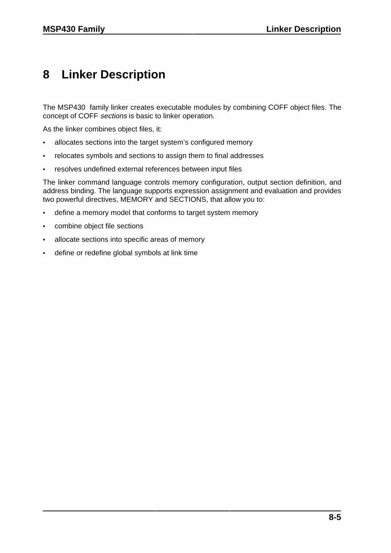
MSP430 Family Linker Description
8-5
8 Linker Description
The MSP430 family linker creates executable modules by combining COFF object files. Theconcept of COFF sections is basic to linker operation.
As the linker combines object files, it:
• allocates sections into the target system’s configured memory
• relocates symbols and sections to assign them to final addresses
• resolves undefined external references between input files
The linker command language controls memory configuration, output section definition, andaddress binding. The language supports expression assignment and evaluation and providestwo powerful directives, MEMORY and SECTIONS, that allow you to:
• define a memory model that conforms to target system memory
• combine object file sections
• allocate sections into specific areas of memory
• define or redefine global symbols at link time

Linker Description MSP430 Family
8-6
8.1 Linker Development Flow
The following figure illustrates the linker’s role in the assembly language developmentprocess. The linker accepts several types of files as input, including object files, commandfiles, libraries, and partially linked files. The linker creates an executable COFF objectmodule that can be downloaded to one of several development tools or executed by aMSP430 device.
Assembler Source
Assembler
COFF ObjectFiles
Linker
ExecutableCOFF Objekt
Files
MacroSource Files
Archiver
Macro Library
ObjectFormat
Converter
Archiver
Library ofObject Files
EPROMProgrammer
AbsoluteLister
MSP430 Software EvaluationModuleSimulator
In-CircuitEmulator
Figure 8.1: Linker Development Flow

MSP430 Family Linker Description
8-7
8.2 Invoking the Linker
The general syntax for invoking the linker is:
lnk430 [-option] filename1 ... filenamen
lnk430 is the command that invokes the linker.
options
can appear anywhere on the command line or in a linker command file. (Options arediscussed in Section 8.3.)
filenames
can be object files, linker command files, or archive libraries. The default extensionfor all input files is .obj; any other extension must be explicitly specified. The linkercan determine whether the input file is an object file or an ASCII file that containslinker commands. The default output filename is a.out.
There are three methods for invoking the linker:
• Specify options and filenames on the command line. This example links two files, file1.objand file2.obj, and creates an output module named link.out.
lnk430 file1.obj file2.obj -o link.out
• Enter the lnk430 command with no filenames and no options; the linker will prompt forthem:
Command files :Object files [.obj] :Output files [ ] :Options :
For command files, enter one or more command file names.
For object files, enter one or more object file names. The default extension is .obj.Separate the filenames with spaces or commas; if the last character is a comma, thelinker will prompt for an additional line of object file names.
The output file is the name of the linker output module. This overrides any -o optionsentered with any of the other prompts. If there are no -o options and you do not answerthis prompt, the linker will create an object file with a default filename of a.out.
The options prompt is for additional options, although you can also enter them in acommand file. Enter them with hyphens, just as you would on the command line.
• Put filenames and options in a linker command file. For example, assume the filelinker.cmd contains the following lines:
-o link.outfile1.objfile2.obj
Now you can invoke the linker from the command line; specify the command file name asan input file:
lnk430 linker.cmd

Linker Description MSP430 Family
8-8
When you use a command file, you can also specify other options and files on thecommand line. For example, you could enter:
lnk430 -m link.map linker.cmd file3.obj
The linker reads and processes a command file as soon as it encounters it on thecommand line, so it links the files in this order: file1.obj, file2.obj, and file3.obj. Thisexample creates an output file called link.out and a map file called link.map.

MSP430 Family Linker Description
8-9
8.3 Linker Options
Linker options control linking operations. They can be placed on the command line or in acommand file. Linker options must be preceded by a hyphen (-). The order in which optionsare specified is unimportant, except for the -l and -i options. Options are separated fromarguments (if they have them) by an optional space.
Option Description-a Produce an absolute, executable module. This is the default; if neither
-a nor -r is specified, the linker acts as if -a is specified.-ar Produce a relocatable, executable object module.-e global symbol Define a global symbol that specifies the primary entry point for the
output module.-f fill value Set the default fill value for holes within output sections; fill value is a
16–bit constant.-h Make all global symbols static.-i dir † Alter the library–search algorithm to look in dir before looking in the
default location. This option must appear before the -l option.-l filename † Name an archive library file as linker input; filename is an archive
library name.-m filename † Produce a map or listing of the input and output sections, including
holes, and place the listing in filename.-o filename † Name the executable output module. The default filename is a.out.-q Request a quiet run (suppress the banner).-r Retain relocation entries in the output module.-s Strip symbol table information and line number entries from the output
module.-u symbol Place an unresolved external symbol into the output module's symbol
table.-x Force rereading of libraries. Resolves “back" references.-z filename † Produce an additional byte formatted ASCII file loadable by the
evaluation module. The default filename is the output filename withthe extension .txt.
† The filename must follow operating system conventions.
Table 8.1: Linker Options Summary
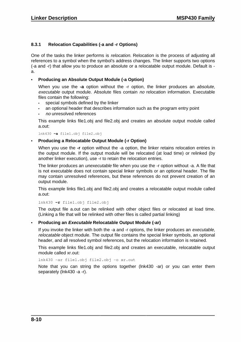
Linker Description MSP430 Family
8-10
8.3.1 Relocation Capabilities (-a and -r Options)
One of the tasks the linker performs is relocation. Relocation is the process of adjusting allreferences to a symbol when the symbol’s address changes. The linker supports two options(-a and -r) that allow you to produce an absolute or a relocatable output module. Default is -a.
• Producing an Absolute Output Module (-a Option)
When you use the -a option without the -r option, the linker produces an absolute,executable output module. Absolute files contain no relocation information. Executablefiles contain the following:• special symbols defined by the linker• an optional header that describes information such as the program entry point• no unresolved references
This example links file1.obj and file2.obj and creates an absolute output module calleda.out:
lnk430 -a file1.obj file2.obj
• Producing a Relocatable Output Module (-r Option)
When you use the -r option without the -a option, the linker retains relocation entries inthe output module. If the output module will be relocated (at load time) or relinked (byanother linker execution), use -r to retain the relocation entries.
The linker produces an unexecutable file when you use the -r option without -a. A file thatis not executable does not contain special linker symbols or an optional header. The filemay contain unresolved references, but these references do not prevent creation of anoutput module.
This example links file1.obj and file2.obj and creates a relocatable output module calleda.out:
lnk430 -r file1.obj file2.obj
The output file a.out can be relinked with other object files or relocated at load time.(Linking a file that will be relinked with other files is called partial linking)
• Producing an Executable Relocatable Output Module (-ar)
If you invoke the linker with both the -a and -r options, the linker produces an executable,relocatable object module. The output file contains the special linker symbols, an optionalheader, and all resolved symbol references, but the relocation information is retained.
This example links file1.obj and file2.obj and creates an executable, relocatable outputmodule called xr.out:
lnk430 -ar file1.obj file2.obj -o xr.out
Note that you can string the options together (lnk430 -ar) or you can enter themseparately (lnk430 -a -r).

MSP430 Family Linker Description
8-11
• Relocating or Relinking an Absolute Output Module
The linker issues a warning message (but continues executing) when it encounters a filethat contains no relocation or symbol table information. Relinking an absolute file can besuccessful only if each input file contains no information that needs to be relocated (thatis, each file has no unresolved references and is bound to the same virtual address that itwas bound to when the linker created it).
8.3.2 Define an Entry Point (-e global symbol Option)
The memory address that a program begins executing from is called the entry point. Whena loader loads a program into target memory, the program counter must be initialized to theentry point; the PC then points to the beginning of the program.
The linker can assign one of four possible values to the entry point. These values are listedbelow in the order in which the linker tries to use them. If you use one of the first threevalues, it must be an external symbol in the symbol table. Possible entry point valuesinclude:
• The value specified by the -e option. The syntax is -e global symbol where global symboldefines the entry point and must appear as an external symbol in one of the input files.
• Zero (default value).
This example links file1.obj and file2.obj. The symbol begin is the entry point; begin must bedefined as external in file1 or file2.
lnk430 -e begin file1.obj file2.obj
8.3.3 Set Default Fill Value (-f cc Option)
The -f option fills the holes formed within output sections or initializes uninitialized sectionswhen they are combined with initialized sections. This allows you to initialize memory areasduring link time without reassembling a source file. The argument cc is a 16–bit constant (upto four hexadecimal digits). If you do not use -f, the linker uses 0 as the default fill value.
This example fills holes with the hexadecimal value ABCD:
lnk430 -f 0ABCDh file1.obj file2.obj
8.3.4 Make All Global Symbols Static (-h Option)
The -h option makes output global symbols static. This is useful when you are using partiallinking to link related object files into self–contained modules, then relinking the modulestogether into a final system. If there are global symbols in one module that have the samename as global symbols in other modules, but you want to treat them as separate symbols,use the -h option when building the modules. The global symbols in the modules, whichwould normally be visible to the other modules and cause possible redefinition problems inthe final link, are made static so they are not visible to the other modules.

Linker Description MSP430 Family
8-12
For example, assume b1.obj, b2.obj, and b3.obj are related and reference a global variableGLOB. Also assume that d1.obj, d2.obj, and d3.obj are related and reference a separateglobal variable GLOB. You can link the related files together with the following commands:
lnk430 -h -r b1.obj b2.obj b3.obj -o bpart.out lnk430 -h -r d1.obj d2.obj d3.obj -o dpart.out
The -h option guarantees that bpart.out and dpart.out will not have global symbols andtherefore two distinct versions of GLOB exist. The -r option is used to allow bpart.out anddpart.out to retain their relocation entries. These two partially linked files can then be linkedtogether safely with the following command:
lnk430 bpart.out dpart.out -o system.out
8.3.5 Alter the Library Search Algorithm (-i dir Option/C_DIR)
Usually, when you want to specify a library as linker input, you simply enter the library nameas you would any other input filename; the linker looks for the library in the current directory.For example, suppose the current directory contains the library object.lib. Assume that thislibrary defines symbols that are referenced in the file file1.obj. This is how you link the files:
lnk430 file1.obj object.lib
If you want to use a library that is not in the current directory, use the -l (lowercase “L") linkeroption. The syntax for this option is -l filename. The filename is the name of an archivelibrary; the space between -l and the filename is optional.
You can augment the linker's directory search algorithm by using the -i linker option or theenvironment variable. The linker searches for object libraries in the following order:
1) It searches directories named with the -i linker option.2) It searches directories named with the environment variable C_DIR.3) If C_DIR is not set, it searches directories named with the assembler's environment
variable, A_DIR.4) It searches the current directory.
-i Linker Options
The -i linker option names an alternate directory that contains object libraries. The syntax forthis option is -i dir. dir names a directory that contains object libraries; the space between -iand the directory name is optional. When the linker is searching for object libraries namedwith the -l option, it searches through directories named with -i first. Each -i option specifiesonly one directory, but you can use several -i options per invocation. When you use the -ioption to name an alternate directory, it must precede the -l option on the command line or ina command file.

MSP430 Family Linker Description
8-13
As an example, assume that there are two archive libraries called r.lib and lib2.lib. The tablebelow shows the directories that r.lib and lib2.lib reside in, how to set environment variable,and how to use both libraries during a link.
Pathname Invocation Command
DOS \ld and \ld2 lnk430 f1.obj f2.obj -i\ld -i\ld2 -lr.lib -llib2.lib
Environment Variable (C_DIR)
An environment variable is a system symbol that you define and assign a string to. The linkeruses an environment variable named C_DIR to name alternate directories that contain objectlibraries. The command for assigning the environment variable is:
DOS set C_DIR=pathname;another pathname ...
The pathnames are directories that contain object libraries. Use the -l option on thecommand line or in a command file to tell the linker which libraries to search for.
As an example, assume that two archive libraries called r.lib and lib2.lib reside in ld and ld2directories. The table below shows the directories that r.lib and lib2.lib reside in, how to setthe environment variable, and how to use both libraries during a link.
Pathname Invocation Command
DOS \ld and \ld2 set C_DIR=\ld;\ld2lnk430 f1.obj f2.obj -l r.lib -l lib2.lib
Note that the environment variable remains set until you reboot the system or reset thevariable by entering:
DOS set C_DIR=
The assembler uses an environment variable named A_DIR to name alternate directoriesthat contain copy/include files or macro libraries. If C_DIR is not set, the linker will search forobject libraries in the directories named with A_DIR.

Linker Description MSP430 Family
8-14
8.3.6 Create a Map File (-m filename Option)
The -m option creates a link map listing and puts it in filename. This map describes:
• Memory configuration.
• Input and output section allocation.
• The addresses of external symbols after they have been relocated.
The map file contains the name of the output module and the entry point; it may also containup to three tables:
• A table showing the new memory configuration if any nondefault memory is specified.
• A table showing the linked addresses of each output section and the input sections thatmake up the output sections.
• A table showing each external symbol and its address. This table has two columns: theleft column contains the symbols sorted by name, and the right column contains thesymbols sorted by address.
This example links file1.obj and file2.obj and creates a map file called map.out:
lnk430 file1.obj file2.obj -m map.out
8.3.7 Name an Output Module (-o filename Option)
The linker creates an output module when no errors are encountered. If you do not specifya filename for the output module, the linker gives it the default name a.out. If you want towrite the output module to a different file, use the -o option. The filename is the new outputmodule name.
This example links file1.obj and file2.obj and creates an output module named run.out:
lnk430 -o run.out file1.obj file2.obj
8.3.8 Specify a Quiet Run (-q Option)
The -q option suppresses the linker’s banner when -q is the first option on the command lineor in a command file. This option is useful for batch operation.

MSP430 Family Linker Description
8-15
8.3.9 Strip Symbolic Information (-s Option)
The -s option creates a smaller output module by omitting symbol table information and linenumber entries. The -s option is useful for production applications when you must create thesmallest possible output module.
This example links file1.obj and file2.obj and creates an output module, stripped off linenumbers and symbol table information, named nosym.out:
lnk430 -o nosym.out -s file1.obj file2.obj
Note that using the -s option limits later use of a symbolic debugger and may prevent a filefrom being relinked.
8.3.5 Introduce an Unresolved Symbol (-u symbol Option)
The -u option introduces an unresolved symbol into the linker’s symbol table. This forces thelinker to search through a library and include the member that defines the symbol. Note thatthe linker must encounter the -u option before it links in the member that defines the symbol.
For example, suppose a library named rts.lib contains a member that defines the symbolsymtab; none of the object files you are linking reference symtab. Suppose you plan to relinkthe output module, however, and you would like to include the library member that definessymtab in this link. Using the -u option as shown below forces the linker to search rts.lib forthe member that defines symtab and to link in the member.
lnk430 -u symtab file1.obj file2.obj rts.lib
If you do not use -u, this member is not included, because there is no explicit reference to itin file1.obj or file2.obj.
8.3.6 Exhaustively Read Libraries (-x option)
The linker normally reads input files, archive libraries included, only once: when they areencountered on the command line or in the command file. When an archive is read, anymembers that resolve references to undefined symbols are included in the link. If an input filelater references a symbol defined in a previously read archive library (this is called a backreference), the reference will not be resolved.
You can force the linker to repeatedly reread all libraries with the -x option. The linker willcontinue to reread libraries until no more references can be resolved. For example, if a.libcontains a reference to a symbol defined in b.lib, and b.lib contains a reference to a symboldefined in a.lib, you can resolve the mutual dependencies by listing one of the libraries twice,as in:
lnk430 -la.lib -lb.lib -la.lib
or you can force the linker to do it for you:
lnk430 -x -la.lib -lb.lib
Linking with the -x option may be slower, so you should use the option only as needed.

Linker Description MSP430 Family
8-16
8.4 Command Files
Linker command files allow you to put linking information in a file; this is useful when youoften invoke the linker with the same information. Linker command files are also usefulbecause they allow you to use the MEMORY and SECTIONS directives to customize yourapplication. You must use these directives in a command file; you cannot use them on thecommand line. Command files are ASCII files that contain one or more of the following:
• Input file names, which specify object files, archive libraries, or other command files. (If acommand file calls another command file as input, this statement must be the laststatement in the calling command file. The linker does not return from called commandfiles.)
• Linker options, which can be used in the command file in the same manner that they areused on the command line.
• The MEMORY and SECTIONS linker directives. The MEMORY directive defines thetarget memory configuration. The SECTIONS directive controls how sections are builtand allocated.
• Assignment statements, which define and assign values to global symbols.
To invoke the linker with a command file, enter the lnk430 command and follow it with thename of the command file:
lnk430 command file name
The linker processes input files in the order that it encounters them. If the linker recognizes afile as an object file, it links the file. Otherwise, it assumes that a file is a command file andbegins reading and processing commands from it.
The example shows a sample linker command file called link.cmd.
/******************************************************************/ /* Sample Linker Command File */ /******************************************************************/ a.obj /* First input filename */ b.obj /* Second input filename */ -o prog.out /* Option to specify output file */ -m prog.map /* Option to specify map file */
Example 8.1: Linker Command File
This sample file contains only filenames and options. (Note that you can place comments ina command file by delimiting them with /* and */.) To invoke the linker with this command file,enter:
lnk430 link.cmd
You can place other parameters on the command line when you use a command file:
lnk430 -r link.cmd c.obj d.obj
The linker processes the command file as soon as it encounters it, so a.obj and b.obj arelinked into the output module before c.obj and d.obj.

MSP430 Family Linker Description
8-17
You can specify multiple command files. If, for example, you have a file called names.lst thatcontains filenames and another file called dir.cmd that contains linker directives, you couldenter:
lnk430 names.lst dir.cmd
One command file can call another command file; this type of nesting is limited to 16 levels.If a command file calls another command file as input, this statement must be the laststatement in the calling command file.
Blanks and blank lines that appear in a command file are insignificant except as delimiters.This applies to the format of linker directives in a command file, also. The following exampleshows a sample command file that contains linker directives. (Linker directive formats arediscussed in later sections.)
/***************************************************************/
/* Sample Linker Command File with Directives */
/***************************************************************/
a.obj b.obj c.obj /* Input filenames */
-o prog.out -m prog.map /* Options */
MEMORY /* MEMORY directives */
{
RAM: origin = 200h length = 0100h
ROM: origin = 0F000h length = 1000h
}
SECTIONS /* SECTION directives */
{
.text: > ROM
.data: > ROM
.bss: > RAM
}
Example 8.2: Command File With Linker Directives

Linker Description MSP430 Family
8-18
The following names are reserved as keywords for linker directives. Do not use them assymbol or section names in a command file.
align GROUP originALIGN l (lowercase L) ORIGINattr len pageATTR length PAGEblock LENGTH rangeBLOCK load runCOPY LOAD RUNDSECT MEMORY SECTIONSf NOLOAD spareFILL o typefill org TYPEgroup UNION
Constants in Command Files
Constants can be specified with either of two syntax schemes: the scheme used forspecifying decimal, octal, or hexadecimal constants used in the assember or the schemeused for integer constants in "C" syntax.

MSP430 Family Linker Description
8-19
8.5 Object Libraries
An object library is a partitioned archive file that contains complete object files as members.Usually, a group of related modules are grouped together into a library. When you specify anobject library as linker input, the linker includes any members of the library that defineexisting unresolved symbol references. You can use the MSP430 archiver to build andmaintain libraries.
Using object libraries can reduce link time and can reduce the size of the executable module.If a normal object file that contains a function is specified at link time, it is linked whether it isused or not; however, if that same function is placed in an archive library, it is included only ifit is referenced.
The order in which libraries are specified is important because the linker includes only thosemembers that resolve symbols that are undefined when the library is searched. The samelibrary can be specified as often as necessary; it is searched each time it is included, or the -x option may be used. A library has a table that lists all external symbols defined in thelibrary; the linker searches through the table until it determines that it cannot use the libraryto resolve any more references.
This example links several files and libraries. Assume the following:
• Input files f1.obj and f2.obj both reference an external function named clrscr.
• Input file f1.obj references the symbol origin.
• Input file f2.obj references the symbol fillclr.
• Library libc.lib, member 0, contains a definition of origin.
• Library liba.lib, member 3, contains a definition of fillclr.
• Member 1 of both libraries defines clrscr.
If you enter lnk430 f1.obj liba.lib f2.obj libc.lib:
• Member 1 of liba.lib satisfies both references to clrscr because the library is searchedand clrscr is defined before f2.obj references it.
• Member 0 of libc.lib satisfies the reference to origin.
• Member 3 of liba.lib satisfies the reference to fillclr.
If, however, you enter lnk430 f1.obj f2.obj libc.lib liba.lib, the references to clrscr are satisfiedby member 1 of libc.lib.
If none of the linked files reference symbols defined in a library, you can use the -u option toforce the linker to include a library member. The next example creates an undefined symbolrout1 in the linker’s global symbol table:
lnk430 -u rout1 libc.lib
If any members of libc.lib define rout1, the linker includes those members. Note that it is notpossible to control the allocation of individual library members; members are allocatedaccording to the SECTIONS directive default allocation algorithm.

Linker Description MSP430 Family
8-20
8.6 The MEMORY Directive
The linker determines where output sections should be allocated into memory; the linkermust have a model of target memory to accomplish this task. The MEMORY directive allowsyou to specify a model of target memory so that you can define the types of memory yoursystem contains and the address ranges they occupy. The linker maintains the model as itallocates output sections and uses the model to determine which memory locations can beused for object code.
The memory configurations of MSP430 systems differ from application to application. TheMEMORY directive allows you to specify a variety of configurations. After you use theMEMORY directive to define a memory model, you can use the SECTIONS directive toallocate output sections into defined memory.
8.6.1 Default Memory Model
The linker’s default memory model is based on the MSP430 architecture. This modelassumes that the following memory is available:
• 256 bytes of RAM, beginning at location 200h
• 4K bytes of ROM, beginning at location 0F000h.
If you do not use the MEMORY directive, the linker uses this default memory model.
8.6.2 MEMORY Directive Syntax
The MEMORY directive identifies ranges of memory that are physically present in the targetsystem and can be used by a program. Each range of memory has several characteristics:
• Name
• Starting address
• Length
• Optional set of attributes
• Optional fill specification
When you use the MEMORY directive, be sure to identify all the memory ranges that areavailable to load code into. Any memory that you do not explicitly account for with theMEMORY directive is unconfigured. The linker does not place any part of a program intounconfigured memory. You can represent nonexistent memory spaces by simply notincluding an address range in a MEMORY directive statement.

MSP430 Family Linker Description
8-21
The MEMORY directive is specified in a command file by the word MEMORY (uppercase),followed by a list of memory range specifications enclosed in braces. For example, you coulduse the MEMORY directive to specify a memory configuration as follows:
/**********************************************************//* Sample command file with MEMORY directive *//**********************************************************/file1.obj file2.obj /* Input files */–o prog.out /* Options */
MEMORY{
RAM: origin = 200h length = 100hROM: origin = 0F000h length = 1000h
}
You could then use the SECTIONS directive to link the .bss section into the memory areanamed RAM, .text into ROM, and .data into ROM.
The general syntax for the MEMORY directive is:
MEMORY{
name 1 [(attr)] : origin = constant , length = constant, fill = constant..name n [(attr)] : origin = constant , length = constant, fill = constant
}
name Names a memory range. A memory name may be 1 to 8 characters; valid charactersinclude A-Z, a-z, $, ., and _. The names have no special significance to the linker;they simply identify memory ranges. Memory range names are internal to the linkerand are not retained in the output file or in the symbol table.
attr Specifies 1 to 4 attributes associated with the named range. Attributes are optional;when used, they must be enclosed in parentheses. Attributes can restrict theallocation of output sections into certain memory ranges. If you do not use anyattributes, you can allocate any output section into any range with no restrictions. Anymemory for which no attributes are specified (including all memory in the defaultmodel) has all four attributes. Valid attributes include:
R Specifies that the memory can be read.
W Specifies that the memory can be written to.
X Specifies that the memory can contain executable code.
I Specifies that the memory can be initialized.
origin Specifies the starting address of a memory range and may be abbreviated as org oro. The value, specified in bytes, is a long integer constant and may be decimal, octal,or hexadecimal.
length Specifies the length of a memory range and may be abbreviated as len or l. Thevalue, specified in bytes, is a long integer constant and may be decimal, octal, orhexadecimal.

Linker Description MSP430 Family
8-22
fill Specifies a fill character for the memory range and may be abbreviated as f. Fills areoptional. The value is a two–byte integer constant and may be decimal, octal, orhexadecimal. The fill value will be used to fill any areas of the memory range that arenot allocated to a section.
Note: Filling Memory Ranges
If you specify fill values for large memory ranges, your output file will be very largebecause filling a memory range (even with zeros) causes raw data to be generated for allunallocated blocks of memory in the range.
The following example specifies a memory range with the R and W attributes and a fillconstant of 0FFFFh:
MEMORY{
RFILE (RW) : o = 02h, l = 0FEh, f = 0FFFFh}
You normally use the MEMORY directive in conjunction with the SECTIONS directive tocontrol allocation of output sections. After you use the MEMORY directive to specify thetarget system's memory model, you can use the SECTIONS directive to allocate outputsections into specific named memory ranges or into memory that has specific attributes.

MSP430 Family Linker Description
8-23
8.7 The SECTIONS Directive
The SECTIONS directive tells the linker how to combine sections from input files intosections in the output module and where to place the output sections in memory. Insummary, the SECTIONS directive:
• Describes how input sections are combined into output sections.
• Defines output sections in the executable program.
• Specifies where output sections are placed in memory (in relation to each other and tothe entire memory space).
• Permits renaming of output sections.
8.7.1 Default Sections Configuration
If you do not specify a SECTIONS directive, the linker uses a default algorithm for combiningand allocating the sections.
8.7.2 SECTIONS Directive Syntax
The SECTIONS directive is specified in a command file by the word SECTIONS(uppercase), followed by a list of output section specifications enclosed in braces.
The general syntax for the SECTIONS directive is:
SECTIONS { name : [ property, property, property, ... ] name : [ property, property, property, ... ] name : [ property, property, property, ... ]}
Each section specification, beginning with name, defines an output section. (An outputsection is a section in the output file.) After the section name is a list of properties that definethe section’s contents and how it is allocated. The properties may be separated by optionalcommas. Possible properties for a section are:
load allocation defines where in memory the section is to be loaded.Syntax: load = allocation or
allocation or > allocation
run allocation defines where in memory the section is to be run.Syntax: run = allocation or
run > allocation
input sections defines the input sections composing the section.Syntax: { input_sections }

Linker Description MSP430 Family
8-24
section type defines flags for special section types.Syntax: type = COPY or
type = DSECT ortype = NOLOAD
For more information on section types, see Section 8.12.
fill value defines the value used to fill uninitialized "holes"Syntax: fill = value or
name: ... { ... } = valueFor more information on creating and filling holes, see Section 8.14.
The example shows a SECTIONS directive in a sample linker command file. The figure onthe next page shows how these sections are allocated in memory.
/****************************************************************/
/* Sample command file with SECTIONS directives */
/****************************************************************/
file1.obj file2.obj /* Input files */
-o prog.out /* Options */
SECTIONS
{
.text: load = ROM
.const: load = ROM, run = 0D000h
.bss: load = RAM
.vectors: load = 0FFE0h
{
t1.obj(.intvec1)
t2.obj(.intvec2)
endvec = .;
}
.data: align = 16
}
Example 8.3: The SECTIONS Directive

MSP430 Family Linker Description
8-25
The figure shows the five output sections defined by the sections directive in the lastexample: .vectors, .text, .const, .bss, and .data.
- allocated in ROM The .text section combines the .text sectionsfrom file1.obj and file2.obj. The linker combinesall sections named .text into section.
- bound at 0FFE0hThe .vectors section is composed of the .intvec1 section from t1.obj and the .intvec2section from t2.obj.
The .const section combines the .const sec-tions from file1.obj and file2.obj. The applicationmust relocate the section to run at 0D000h.
- allocated in RAM The .bss section combines the .bss sectionsfrom file1.obj and file2.obj
- aligned on 16-byte boundary
The .data section combines the .data sectionsfrom file1.obj and file2.obj. The linker will place itanywhere there is space for it (in RAM in thisillustration) and align it to a 16-byte boundary.
.text
.vectors
.const
.bss
.data
ROM
RAM
Figure 8.2: Section Allocation

Linker Description MSP430 Family
8-26
8.7.3 Specifying the Address of Output Sections (Allocation)
The linker assigns each output section two locations in target memory: the location wherethe section will be loaded and the location where it will be run. Usually, these are the same,and you can think of each section as having only a single address. In any case, the processof locating the output section in the target’s memory and assigning its address(es) is calledallocation.
If you do not tell the linker how a section is to be allocated, it uses a default algorithm toallocate the section. Generally, the linker puts sections wherever they fit into configuredmemory. You can override this default allocation for a section by defining it within aSECTIONS directive and providing instructions on how to allocate it.
You control allocation by specifying one or more allocation parameters. Each parameterconsists of a keyword, an optional equals sign or greater–than sign, and a value optionallyenclosed in parentheses. If load and run allocation is separate, all parameters following thekeyword LOAD apply to load allocation, and those following RUN apply to run allocation.Possible allocation parameters are:
binding allocates a section at a specific address.text: load = 0x1000
memory allocates the section into a range defined in the MEMORY directive with thespecified name or attributes.text: load > ROM
alignment specifies that the section should start on an address boundary.text: align = 0x100
blocking specifies that the section must fit between two address boundaries: forexample, on a single data page..text: block(0x100)
For the load (usually the only) allocation, you may simply use a greater–than sign and omitthe LOAD keyword:
.text: > ROM .text: {...} > ROM
.text: > 0x4000
If more than one parameter is used, you can string them together as follows:
.text: > ROM align 16
Or if you prefer, use parentheses for readability:
.text: load = (ROM align(16))
Binding
You can supply a specific starting address for an output section by following the sectionname with an address:
.text: 0x4000

MSP430 Family Linker Description
8-27
This example specifies that the .text section must begin at location 4000h. The bindingaddress must be a 16–bit constant.
Output sections can be bound anywhere in configured memory (assuming there is enoughspace), but they cannot overlap. If there is not enough space to bind a section to a specifiedaddress, the linker issues an error message.
Note: Binding and Alignment or Named Memory Are Incompatible
You cannot bind a section to an address if you use alignment or named memory. If you tryto do this, the linker issues an error message.
Memory
You can allocate a section into a memory range that is defined by the MEMORY directive.This example names ranges and links sections into them:
MEMORY{
ROM (RIX) : origin = 0h, length = 1000hRAM (RWIX): origin = 0D000h, length = 1000h
}SECTIONS{
.text : > ROM
.data : > RAM, ALIGN=64
.bss : > RAM}
In this example, the linker places .text into the area called ROM. The .data and .bss outputsections are allocated into RAM. You can align a section within a named memory range; the.data section is aligned on a 64–word boundary within the RAM range.
Similarly, you can link a section into an area of memory that has particular attributes. To dothis, specify a set of attributes (enclosed in parentheses) instead of a memory name. Usingthe same MEMORY directive declaration, you can specify:
SECTIONS{
.text: > (X) /* .text --> executable memory */
.data: > (RI) /* .data --> read or init memory */
.bss : > (RW) /* .bss --> read or write memory */}
In this example, the .text output section can be linked into either the ROM or RAM areabecause both areas have the X attribute. The .data section can also go into either ROM orRAM because both areas have the R and I attributes. The .bss output section, however,must go into the RAM area because only RAM is declared with the W attribute.

Linker Description MSP430 Family
8-28
You cannot control where in a named memory range a section is allocated, although thelinker uses lower memory addresses first and avoids fragmentation when possible. In thepreceding examples, assuming no other sections had been bound to addresses that wouldinterfere with this allocation process, the .text section would start at address 0. If a sectionmust start on a specific address, use binding instead of named memory.
Alignment and Blocking
You can tell the linker to place an output section at an address that falls on an n–byteboundary, where n is a power of 2. For example:
.text: load = align(32)
allocates .text so that it falls on a 32-byte boundary.
Blocking is a weaker form of alignment that places a section so that it is allocated anywherewithin a “block" of size n. As with alignment, n must be a power of 2. For example:
bss: load = block(0x1000)
allocates .bss so that the entire section is contained in a single 4K–byte data page.
You can use alignment or blocking alone or in conjunction with a memory area, butalignment and blocking cannot be used together.
8.7.4 Specifying Input Sections
An input section specification identifies the sections from input files that are combined toform an output section. The linker combines input sections by concatenating them in theorder specified. The size of an output section is the sum of the sizes of the input sectionsthat make up the output section.
SECTIONS
{
.text:
.data:
.bss :
}
Example 8.4: The Most Common Method of Specifying Section Contents
The linker takes all the .text sections from the input files and combines them into the .textoutput section. The linker concatenates the .text input sections in the order that it encountersthem in the input files. The linker performs similar operations with the .data and .bsssections. You can use this type of specification for any output section.

MSP430 Family Linker Description
8-29
You can explicitly specify the input sections that form an output section. Each input section isidentified by its filename and section name:
SECTIONS{
.text : /* Build .text output section */{
f1.obj(.text) /* Link .text section from f1.obj */f2.obj(sec1) /* Link sec1 section from f2.obj */f3.obj /* Link ALL sections from f3.obj */f4.obj(.text,sec2) /* Link .text and sec2 from f4.obj */
}}
Note that it is not necessary for an input section to have the same name as another it iscombined with or as the output section it becomes part of. If a file is listed with no sections,all of its sections are included in the output section. If any additional input sections have thesame name as an output section but are not explicitly specified by the SECTIONS directive,they are automatically linked in at the end of the output section. For example, if the linkerfound more .text sections in the preceding example and these .text sections were notspecified anywhere in the SECTIONS directive, the linker would concatenate these extrasections after f4.obj(sec2).
The specifications in the example on the page before are actually a shorthand method forthe following:
SECTIONS{
.text: { *(.text) }
.data: { *(.data) }
.bss: { *(.bss) }}
The *(.text) means the unallocated .text sections from all the input files. This format is usefulwhen:
• You want the output section to contain all input sections that have a certain name, butthe output section name is different from the input sections’ names.
• You want the linker to allocate the input sections before it processes additional inputsections or commands within the braces.
Here’s an example that uses this method:
SECTIONS{
.text : {abc.obj(xqt)
*(.text)}
.data : {*(.data)fil.obj(table)
}}

Linker Description MSP430 Family
8-30
In this example, the .text output section contains a named section xqt from file abc.obj,which is followed by all the .text input sections. The .data section contains all the .data inputsections, followed by a named section table from the file fil.obj. Note that this methodincludes all the unallocated sections. For example, if one of the .text input sections wasalready included in another output section when the linker encountered *(.text), the linkercould not include that first .text input section in the second output section.

MSP430 Family Linker Description
8-31
8.8 Specifying a Section’s Runtime Address
It may be necessary or desirable at times to load code into one area of memory and run it inanother. For example, you may have performance–critical code in a ROM–based system.The code must be loaded into ROM but would run much faster if it were in RAM.
The linker provides a simple way to specify this. In the SECTIONS directive, you canoptionally direct the linker to allocate a section twice: once to set its load address and againto set its run address. For example:
.fir: load = ROM, run = RAM
Use the load keyword for the load address and the run keyword for the run address.
8.8.1 Specifying Two Addresses
The load address determines where a loader will place the raw data for the section. Anyreferences to the section (such as labels in it) refer to its run address. The application mustcopy the section from its load address to its run address; this does not happen automaticallyjust by specifying a separate run address.
If you provide only one allocation (either load or run) for a section, the section is allocatedonly once and will load and run at the same address. If you provide both allocations, thesection is actually allocated as if it were two different sections of the same size. This meansthat both allocations occupy space in the memory map and cannot overlay each other orother sections. (The UNION directive provides a way to overlay sections)
If either the load or run address has additional parameters, such as alignment or blocking,list them after the appropriate keyword. After the keyword load, everything having to do withallocation affects the load address until the keyword run is seen, after which everythingaffects the run address. The load and run allocations are completely independent, so anyqualification of one (such as alignment) has no effect on the other. You may also specify runfirst, then load. Use parentheses to improve readability. Examples:
.data: load = ROM, align = 32, run = RAM
(align applies only to load )
.data: load = (ROM align 32), run = RAM
(identical to previous example)
.data: run = RAM, align 32,load = align 16
(align 32 in RAM for run; align 16 anywhere for load)

Linker Description MSP430 Family
8-32
8.8.2 Uninitialized Sections
Uninitialized sections (such as .bss) are not loaded, so the only address of significance is therun address. The linker allocates uninitialized sections only once. If you specify both run andload addresses, the linker warns you and ignores the load address. Otherwise, if you specifyonly one address, the linker treats it as a run address, regardless of whether you call it loador run. Examples:
.bss: load = 0x1000, run = RAM
A warning is issued, load is ignored, space is allocated in RAM. All of the following exampleshave the same effect. The .bss section is allocated in RAM.
.bss: load = RAM
.bss: run = RAM
.bss: > RAM
8.8.3 Referring to the Load Address by Using the .label Directive
Any reference to a normal symbol in a section refers to its runtime address. However, it maybe necessary at runtime to refer to a load–time address. In particular, the code that copies asection from its load address to its run address must know where it was loaded. The .labeldirective in the assembler defines a special type of symbol that refers to the load address ofthe section. Thus, whereas normal symbols are relocated with respect to the run address,.label symbols are relocated with respect to the load address.

MSP430 Family Linker Description
8-33
;-------------------------------------------------------------- ; define a section to be copied from ROM to RAM ;--------------------------------------------------------------
.sect ".fir"
.label fir_load ; load address of section fir: ; run address of section ; <code here> ; code for the section
ret
.label fir_end
fir_len .equ fir_end - fir_load
;-------------------------------------------------------------- ; copy .fir section from ROM into RAM ;--------------------------------------------------------------
.textMOV #fir_len, R4MOV #fir_load, R5MOV #fir, R6
JMP L2 L1: MOV @R5+, 0(R6)
INCD R6 L2: DECD R4
JC L1
;-------------------------------------------------------------- ; jump to section, now in RAM ;--------------------------------------------------------------
call fir ; call runtime address
Linker Command File
/*************************************************************/ /* PARTIAL LINKER COMMAND FILE FOR FIR EXAMPLE */ /*************************************************************/ MEMORY { ROM: origin=4000h length = 4000h RAM: origin=2000h length = 2000h }
SECTIONS { .text: load = ROM .fir: load = ROM, run = RAM }
Example 8.5: Copying a Section From ROM to RAM

Linker Description MSP430 Family
8-34
The figure illustrates the runtime execution of the last example.
.text
.fir (loads here)
.fir (relocated torun here)
fir_load:
fir_end:
fir:
ROM
RAM Application copiessection at runtime
Figure 8.3: Runtime Execution

MSP430 Family Linker Description
8-35
8.9 Using UNION and GROUP Statements
Two SECTIONS statements allow you to conserve memory: GROUP and UNION. Unioningoutput sections causes the linker to allocate the same run address to the sections. Groupingoutput sections causes the linker to allocate them contiguously in memory.
8.9.1 Overlaying Sections With the UNION Statement
For some applications, you may wish to allocate more than one section to run at the sameaddress; for example, you may have several routines you want in on–chip RAM at variousstages of the program's execution. Or you may want several data objects that you know willnot be active at the same time to share a block of memory. The UNION statement within theSECTIONS directive provides a way to allocate several sections at the same run address.
SECTIONS { .text: load = ROM UNION: run = RAM {
.bss1: { file1.obj(.bss) }
.bss2: { file2.obj(.bss) } } .bss3: run = RAM { globals.obj(.bss) } }
Example 8.6: Illustration of the Form of the UNION Statement

Linker Description MSP430 Family
8-36
.text
ROM
RAM
.bss2.bss1
.bss3
Figure 8.4: Runtime Memory Allocation
In the example on the page before, the .bss sections from file1.obj and file2.obj are allocatedat the same address in RAM. The union occupies as much space in the memory map as itslargest component. The components of a union remain independent sections; they aresimply allocated together as a unit.
Allocation of a section as part of a union affects only its run address. Under nocircumstances can sections be overlaid for loading. If an initialized section is a unionmember (an initialized section has raw data, such as .text), its load allocation must beseparately specified. The next example illustrates this.

MSP430 Family Linker Description
8-37
UNION run = RAM
{
.text1: load = ROM, { file1.obj(.text) }
.text2: load = ROM, { file2.obj(.text) }
}
Example 8.7: Illustration of Separate Load Addresses for UNION Sections
.text 1 (load)
.text 2 (load)
ROM
RAM
.text 2 (run) copies at runtime.text 1 (run)
Figure 8.5: Load and Run Memory Allocation
Since the .text sections contain data, they cannot load as a union, although they can be runas a union. Therefore, each requires its own load address. If you fail to provide a loadallocation for an initialized section within a UNION, the linker issues a warning and allocatesload space anywhere it fits in configured memory.
Uninitialized sections are not loaded and do not require load addresses.

Linker Description MSP430 Family
8-38
The UNION statement applies only to allocation of run addresses, so it is redundant tospecify a load address for the union itself. For purposes of allocation, the union is treated asan uninitialized section: any one allocation specified is considered a run address, and, if bothare specified, the linker issues a warning and ignores the load address.
8.9.2 Grouping Output Sections Together
The SECTIONS directive has a GROUP option that forces several output sections to beallocated contiguously. For example, assume that a section named term_rec contains atermination record for a table in the .data section. You can force the linker to allocate .dataand term_rec together:
SECTIONS{
.text /* Normal output section */
.bss /* Normal output section */GROUP 1000h : /* Specify a group of sections */{
.data /* First section in the group */term_rec /* Allocated immediately after .data */
}}
You can use binding, alignment, or named memory to allocate a GROUP in the same way asingle output section is allocated. In the preceding example, the GROUP is bound to address1000h. This means that .data is allocated at 1000h, and term_rec follows it in memory.
Note: You Cannot Specify Addresses for Sections Within a Group
When you use the GROUP option, binding, alignment, or allocation into named memorycan be specified for the group only. You cannot use binding, named memory, or alignmentfor sections within a group.

MSP430 Family Linker Description
8-39
8.11 Default Allocation Algorithm
The MEMORY and SECTIONS directives provide flexible methods for building, combining,and allocating sections. Any memory locations or sections that you choose not to specify,however, must still be handled by the linker. The linker uses default algorithms to build andallocate sections within the specifications you supply.
8.11.1 Default Allocation
If you do not use any MEMORY or SECTIONS directives, the linker acts as though thefollowing definitions were specified:
MEMORY{
RAM : origin = 200h length = 100hROM : origin = 0F000h length = 1000h
}SECTIONS{
.bss : > RAM
.text : > ROM
.data : > ROM
}
All .bss input sections are concatenated to form one .bss output section linked into. All .datainput sections are combined to form a .data output section, which is linked into ROM. All .textinput sections are concatenated to form a .text output section, which is linked into ROMstarting at location 0F000h.
Unless you specify otherwise with a MEMORY directive, the linker assumes theconfiguration specified above. That is, the only memory that the linker uses to build yourprogram is:
• 256 bytes starting at location 0200h,
• 4K bytes starting at location 0F000h.
If there are additional input sections in the input files (specifically, named sections), the linkerlinks them in after the default sections have been linked. Input sections that have the samename are combined into a single output section with this name. The linker allocates theseadditional output sections into memory wherever there is room. Usually, it is desirable to useexplicit SECTIONS directives to tell the linker where to place named sections.
Note: The SECTIONS Directive
If a SECTIONS directive is specified, the linker performs no part of the default allocation.Allocation is performed according to the rules specified by the SECTIONS directive andthe general algorithm described below.

Linker Description MSP430 Family
8-40
8.11.2 General Rules for Forming Output Sections
An output section can be formed in one of two ways:
Rule 1 As the result of a SECTIONS directive definition.
Rule 2 By combining input sections with the same names into output sections that are notdefined in a SECTIONS directive.
If an output section is formed as a result of a SECTIONS directive (rule 1), this definitioncompletely determines the section’s contents.
An output section can also be formed when input sections are encountered that are notspecified by any SECTIONS directive (rule 2). In this case, the linker combines all such inputsections that have the same name into an output section with this name. For example,suppose the files f1.obj and f2.obj both contain named sections called Vectors and that theSECTIONS directive does not define an output section to contain them. The linker combinesthe two Vectors sections from the input files into a single output section named Vectors,allocates it into memory, and includes it in the output file.
After the linker determines the composition of all the output sections, it must allocate theminto configured memory. The MEMORY directive specifies which portions of memory areconfigured, or if there is no MEMORY directive, the linker uses the default configuration.
The linker’s allocation algorithm attempts to minimize memory fragmentation. This allowsmemory to be used more efficiently and increases the probability that your program will fitinto memory. This is the algorithm:
1) Output sections for which you have supplied a specific binding address are placed inmemory at that address.
2) Output sections that are included in a specific, named memory range or that havememory attribute restrictions are allocated. Each output section is placed into the firstavailable space within the named area, considering alignment where necessary.
3) Output sections that have zero length are allocated at the beginning of the firstappropriate memory area unless they are part of a group.
4) Any remaining sections are allocated in the order in which they are defined. Sections notdefined in a SECTIONS directive are allocated in the order in which they areencountered. Each output section is placed into the first available memory space,considering alignment where necessary.

MSP430 Family Linker Description
8-41
8.12 Special Section Types (DSECT, COPY, and NOLOAD)
You can assign three special types to output sections: DSECT, COPY, and NOLOAD. Thesetypes affect the way that the program is treated when it is linked and loaded. For example:
SECTIONS{
sec1: load = 2000h, type = DSECT {f1.obj}sec2: load = 4000h, type = COPY {f2.obj}sec3: load = 6000h, type = NOLOAD {f3.obj}
}
• The DSECT type creates a “dummy section" that has the following qualities:
• It is not included in the output section memory allocation. It takes up no memory andis not included in the memory map listing.
• It can overlay other output sections, other DSECTs, and unconfigured memory.
• Global symbols defined in a dummy section are relocated normally. They appear inthe output module's symbol table with the same value they would have if the DSECThad actually been loaded. These symbols can be referenced by other input sections.
• Undefined external symbols found in a DSECT cause specified archive libraries to besearched.
• The section's contents, relocation information, and line number information are notplaced in the output module.
In the preceding example, none of the sections from f1.obj are allocated, but all thesymbols are relocated as though the sections were linked at address 2000h. The othersections can refer to any of the global symbols in sec1.
• A COPY section is similar to a DSECT section, except that its contents and associatedinformation are written to the output module.
• A NOLOAD section differs from a normal output section in one respect: the section'scontents, relocation information, and line number information are not placed in the outputmodule. The linker allocates space for it, it appears in the memory map listing, etc.

Linker Description MSP430 Family
8-42
8.13 Assigning Symbols at Link Time
Linker assignment statements allow you to define external (global) symbols and assignvalues to them at link time. You can use this feature to initialize a variable or pointer to anallocation–dependent value.
8.13.1 Syntax of Assignment Statements
The syntax of assignment statements in the linker is similar to that of assignment statementsin the C language:
symbol = expression; assigns the value of expression to symbolsymbol + = expression; adds the value of expression to symbolsymbol - = expression; subtracts the value of expression from symbolsymbol * = expression; multiplies symbol by expressionsymbol / = expression; divides symbol by expression
The symbol should be defined externally in the program. If it is not, the linker defines a newsymbol and enters it into the symbol table. Assignment statements must be terminated witha semicolon.
The linker processes assignment statements after it allocates all the output sections.Therefore, if an expression contains a symbol, the address used for that symbol reflects thesymbol's address in the executable output file.
For example, suppose a program reads data from one of two tables identified by twoexternal symbols, Table1 and Table2. The program uses the symbol cur_tab as the addressof the current table. cur_tab must point to either Table1 or Table2. You could accomplish thisin the assembly code, but you would need to reassemble the program in order to changetables. Instead, you can use a linker assignment statement to assign cur_tab at link time:
prog.obj /* Input file */cur_tab = Table1; /* Assign cur_tab to one of the tables */
8.13.2 Assigning the SPC to a Symbol
A special symbol, denoted by a dot (.), represents the current value of the SPC duringallocation. The linker's “ . " symbol is analogous to the assembler's "$" symbol. The “ . "symbol can be used only in assignment statements within a SECTIONS directive because “. " is meaningful only during allocation, and SECTIONS controls the allocation process.
For example, suppose a program needs to know the address of the beginning of the .datasection. By using the .global directive, you can create an external undefined variable calledDstart in the program. Then, assign the value of “." to Dstart:
SECTIONS{
.text: {}
.data: { Dstart = .; }
.bss: {}}

MSP430 Family Linker Description
8-43
This defines Dstart to be the ultimate linked address of the .data section. (dstart is assignedbefore .data is allocated.) The linker will relocate all references to Dstart.
A special type of assignment assigns a value to the “." symbol. This adjusts the locationcounter within an output section and creates a hole between two input sections. Any valueassigned to “." to create a hole is relative to the beginning of the section, not to the addressactually represented by “.".
8.13.3 Assignment Expressions
These rules apply to linker expressions:
• Expressions can contain global symbols, constants, and the C language operators listedin the next table.
• All numbers are treated as long (32–bit) integers.
• Constants are identified by the linker in the same manner as they are by the assembler.That is, numbers are recognized as decimal unless they have a suffix (H or h forhexadecimal and Q or q for octal). C language prefixes are also recognized (0 for octaland 0x for hex). Hexadecimal constants must begin with a digit. No binary constants areallowed.
• Symbols within an expression have only the value of the symbol's address. No type–checking is performed.
• Linker expressions can be absolute or relocatable. If an expression contains anyrelocatable symbols (and zero or more constants or absolute symbols), it is relocatable.Otherwise, the expression is absolute. If a symbol is assigned the value of a relocatableexpression, the symbol is relocatable; if it is assigned the value of an absoluteexpression, the symbol is absolute.
The linker supports the C language operators listed in the table in order of precedence.Operators in the same group have the same precedence. Besides the operators listed in thetable, the linker also has an align operator that allows a symbol to be aligned on an n–byteboundary within an output section (n is a power of 2). For example, the expression
. = align(16);
aligns the SPC within the current section on the next 16–byte boundary. Because the alignoperator is a function of the current SPC, it can be used only in the same context as “." —that is, within a SECTIONS directive.

Linker Description MSP430 Family
8-44
Group 1 (Highest Precedence) Group 6
!~-
Logical notBitwise notNegative
& Bitwise AND
Group 2 Group 7
*/
%
MultiplicationDivisionMod
| Bitwise OR
Group 3 Group 8
+-
AdditionMinus
&& Logical AND
Group 4 Group 9
>><<
Arithmetic right shiftArithmetic left shift
|| Logical OR
Group 5 Group 10 (Lowest Precedence)
==! =><
< => =
Equal toNot equal toGreater thanLess thanLess than or equal toGreater than or equal to
=+ =- =* =/ =
AssignmentA + = B ® A = A + BA - = B ® A = A - BA * = B ® A = A * BA / = B ® A = A / B
Table 8.2: Operators in Assignment Expressions
8.13.4 Symbols Defined by the Linker
The linker automatically defines several symbols that a program can use at runtime todetermine where a section is linked. Since these symbols are external, they appear in thelink map. Each symbol can be accessed in any assembly language module if it is declaredwith a .global directive. Values are assigned to these symbols as follows:
.text is assigned the first address of the .text output section.(It marks the beginning of executable code.)
etext is assigned the first address following the .text output section.(It marks the end of executable code.)
.data is assigned the first address of the .data output section.(It marks the beginning of initialized data tables.)
edata is assigned the first address following the .data output section. (It marks the end of initialized data tables.)
.bss is assigned the first address of the .bss output section.(It marks the beginning of uninitialized data.)
end is assigned the first address following the .bss output section.(It marks the end of uninitialized data.)

MSP430 Family Linker Description
8-45
8.14 Creating and Filling Holes
The linker provides you with the ability to create areas within output sections that havenothing linked into them. These areas are called holes. In special cases, uninitializedsections can also be treated as holes. This section describes how the linker handles suchholes and how you can fill holes (and uninitialized sections) with values.
8.14.1 Initialized and Uninitialized Sections
There are two guidelines to remember about the contents of an output section. An outputsection contains either:
• Raw data for the entire section, or
• No raw data.
A section that has raw data is said to be initialized. This means that the object file containsthe actual memory image contents of the section. When the section is loaded, this image isloaded into memory at the section’s specified starting address. The .text and .data sectionsalways have raw data if anything was assembled into them. Named sections defined withthe .sect assembler directive also have raw data.
By default, the .bss section and sections defined with the .usect directive have no raw data(they are uninitialized). They occupy space in the memory map but have no actualcontents. Uninitialized sections typically reserve space in RAM for variables. In the objectfile, an uninitialized section has a normal section header and may have symbols defined in it;no memory image, however, is stored in the section.
8.14.2 Creating Holes
You can create a hole in an initialized output section. A hole is created when you force thelinker to leave extra space between input sections within an output section. When such ahole is created, the linker must follow the first guideline (above) and supply raw data for thehole.
Holes can be created only within output sections. There can also be space between outputsections, but such spaces are not holes.
To create a hole in an output section, you must use a special type of linker assignmentstatement within an output section definition. The assignment statement modifies the SPC(denoted by “ . ") by adding to it, assigning a greater value to it, or aligning it on an addressboundary.

Linker Description MSP430 Family
8-46
The following example uses assignment statements to create holes in output sections:
SECTIONS{
outsect:{
file1.obj(.text) . += 100h; /* Create a hole with size 100h */ file2.obj(.text) . = align(16); /* Create a hole to align the SPC */ file3.obj(.text) }}
The output section outsect is built as follows:
• The .text section from file1.obj is linked in.
• The linker creates a 256–byte hole.
• The .text section from file2.obj is linked in after the hole.
• The linker creates another hole by aligning the SPC on a 16–byte boundary.
• Finally, the .text section from file3.obj is linked in.
All values assigned to the “ . " symbol within a section refer to the relative address within thesection. The linker handles assignments to the “ . " symbol as if the section started ataddress 0 (even if you have specified a binding address). Consider the statement . =align(16) in the example. This statement effectively aligns file3.obj .text to start on a 16–wordboundary within outsect. If outsect is ultimately allocated to start on an address that is notaligned, file3 .text will not be aligned, either.
Expressions that decrement “ . " are illegal. For example, it is invalid to use the -= operator inan assignment to “ . ". The most common operators used in assignments to “ . " are += andalign.
If an output section contains all input sections of a certain type (such as .text), you can usethe following statements to create a hole at the beginning or end of the output section. Forexample:
.text: { .+= 100h; } /* Hole at the beginning */
.data: { *(.data) . += 100h; } /* Hole at the end */

MSP430 Family Linker Description
8-47
Another way to create a hole in an output section is to combine an uninitialized section withan initialized section to form a single output section. In this case, the linker treats theuninitialized section as a hole and supplies data for it. Here is an example of creating a holein this way:
SECTIONS{
outsect:{
file1.obj(.text)file1.obj(.bss) /* This becomes a hole */}
}
Because the .text section has raw data, all of outsect must also contain raw data (firstguideline). Therefore, the uninitialized .bss section becomes a hole.
Note that uninitialized sections become holes only when they are combined with initializedsections. If several uninitialized sections are linked together, the resulting output section isalso uninitialized.
8.14.3 Filling Holes
Whenever there is a hole in an initialized output section, the linker must supply raw data tofill it. The linker fills holes with a 16–bit fill value that is replicated through memory until it fillsthe hole. The linker determines the fill value as follows:
1) If the hole is formed by combining an uninitialized section with an initialized section, youcan specify a fill value for the uninitialized section. Follow the section name with an =sign and a 16–bit constant. For example:
SECTIONS{
outsect:{
file1.obj(.text)file2.obj(.bss) = 0FFh /* Fill this hole */
} /* with 00FFh */}
2) You can also specify a fill value for all the holes in an output section by using the fillkeyword. For example:
SECTIONS{
outsect: fill = 0FF00h /* This fills holes *//* with 0FF00h */
{. += 10h; /* This creates a hole */file1.obj(.text)file1.obj(.bss) /* This creates another hole */
}}

Linker Description MSP430 Family
8-48
3) If you do not specify an initialization value for a hole, the linker fills the hole with the valuespecified with -f. Suppose the command file link.cmd contains the following SECTIONSdirective. For example:
SECTIONS{
.text: { .= 100; } /* Create a 100–word hole */}
Now invoke the linker with the -f option:lnk430 -f 0FFFFh link.cmd
This fills the hole with 0FFFFh.
4) If you do not invoke the linker with the -f option, the linker fills holes with 0s.
Whenever a hole is created and filled in an initialized output section, the hole is identified inthe link map along with the value the linker uses to fill it.
8.14.4 Explicit Initialization of Uninitialized Sections
An uninitialized section becomes a hole only when it is combined with an initialized section.When uninitialized sections are combined with each other, the resulting output sectionremains uninitialized and has no raw data in the output file.
However, you can force the linker to initialize an uninitialized section by specifying an explicitfill value for it in the SECTIONS directive. This causes the entire section to have raw data(the fill value). For example:
SECTIONS{
.bss: fill = 1234h /* Fills .bss with 1234h */}
Note: Filling Sections
Because filling a section (even with 0s) causes raw data to be generated for the entiresection in the output file, your output file will be very large if you specify fill values for largesections or holes.

MSP430 Family Linker Description
8-49
8.14.5 Examples of Using Initialized Holes
The MSP430X201 device has 4K bytes of program memory, starting at location 0F000h. Thetop bytes of this area are reserved for interrupt vectors. Suppose you want to link the .textsections from three object files into a .text output section that begins at address 0F000h.Suppose also that you have a section of initialized interrupt vectors called int_vecs that youwant to link at address 0FFE0h. You could fill the space between the end of the .text sectionand the beginning of the interrupt vectors; the figure shows the space filled with a 1–byte fillvalue of 0EFh and illustrates the desired memory map for program memory.
.text
Vectors
Fill with0EFh
0F000h
0FFE0h0FFFFh
Figure 8.6: Initialized Hole
To obtain the configuration shown in the figure, you must create one large output section thathas .text at the beginning, int_vecs at the end, and a hole between filled with 0EFh:
SECTIONS{
prog 0F000h :fill = OEFEFh /* Define prog and start at 0F000h and */{ /* Specify a fill value */file1.obj(.text) /* Link .text sections from each file */file2.obj(.text)file3.obj(.text). = 0FE0h; /* Create hole to 0FE0h (0FFE0h abs) */file1.obj(int_vecs) /* Link in the vectors section */
}}
The fill value must be a 16–bit constant. To have the value 0EFh in each byte, the fill valuewas specified as 0EFEFh.
Notice that the value 0FE0h, which is assigned to the section program counter ( . ), isrelative to the beginning of the section. Because the section begins at 0F000h, the hole isactually created from the end of the .text section to address 0FFE0h.

Linker Description MSP430 Family
8-50
8.15 Partial (Incremental) Linking
An output file that has been linked can be linked again with additional modules. This isknown as partial linking, or incremental linking. Partial linking allows you to partition largeapplications, link each part separately, and then link all the parts together to create the finalexecutable program.
Follow these guidelines for producing a file that you will relink:
• Intermediate files must have relocation information. Use the -r option when you link thefile the first time.
• Intermediate files must have symbolic information. By default, the linker retains symbolicinformation in its output. Do not use the -s option if you plan to relink a file, because -sstrips symbolic information from the output module.
• Intermediate link steps should be concerned only with the formation of output sectionsand not with allocation. All allocation, binding, and MEMORY directives should beperformed in the final link step.
The following example shows how you can use partial linking:
Step 1: Link the file file1.com; use the -r option to retain relocation information in the outputfile tempout1.out.
lnk430 -r -o tempout1 file1.com
file1.com contains:
SECTIONS{
ss1: {f1.objf2.obj . . .fn.obj
}}

MSP430 Family Linker Description
8-51
Step 2: Link the file file2.com; use the -r option to retain relocation information in the outputfile tempout2.out.
lnk430 -r -o tempout2 file2.com
file2.com contains:
SECTIONS{
ss2: {g1.objg2.obj . . .gn.obj}
}
Step 3: Link tempout1.out and tempout2.out:
lnk430 -m final.map -o final.out tempout1.out tempout2.out

Linker Description MSP430 Family
8-52
8.17 Linker Example
This example links a program called demo.out. There are three object modules, demo.obj,ctrl.obj, and tables.obj.
Assume the following memory configuration:
Address Range Memory Contents
200h to 2FFh internal RAM
1F00h to 1FFFh Data EEPROM
2000h to 3FFFh 8K external RAM
0F000h to 0FFFFh 4K internal program ROM
The program is built from the following elements:
• Executable code, contained in the .text sections of demo.obj and ctrl.obj, must be linkedinto program ROM. The symbol SETUP must be defined as the program entry point.
• A set of interrupt vectors, contained in the int_vecs section of tables.obj, must be linkedat address 0FFE0h in program ROM.
• A table of coefficients, contained in the .data section of tables.obj, must be linked into.EEPROM. The remainder of EEPROM must be initialized with the value 0A26Eh.
• A set of variables, contained in the .bss section of ctrl.obj, must be linked into the RAM.These variables must be preinitialized to 0FFFFh.
• Another .bss section in demo.obj must be linked into external RAM.
The next two figures illustrate the linker command file and the map file for this example.

MSP430 Family Linker Description
8-53
/********************************************************************//* Specify the Linker Options *//********************************************************************/-e SETUP /* Define the entry point */-o demo.out /* Name the output file */-m demo.map /* Create a load map *//********************************************************************//* Specify the Input Files *//********************************************************************/demo.objctrl.objtables.obj/********************************************************************//* Specify the Memory Configuration *//********************************************************************/MEMORY{ RAM : origin = 0200h length = 0100h EEPROM : origin = 1F00h length = 0100h RAMEXT : origin = 2000h length = 2000h ROM : origin = 0F000h length = 1000h}/********************************************************************//* Specify the Output Sections */SECTIONS .text: > ROM /* Link all .text sections into ROM */
int_vecs 0FFE0h: {} /* Link interrupts at FFE0h */
.data: /* Link the data sections */ { tables.obj(.data) . = 100h; /* Create a hole to end of the block */ } = 0A26Eh > EEPROM /* Fill and link into EEPROM */
ctrl_vars: /* Create new section for ctrl vars */ { ctrl.obj(.bss) } = 0FFFFh > RAM /* Fill with 0FFFFh and link to RAM */
.bss > RAMEXT /* Link all remaining .bss sections */}/********************************************************************//* End of Linker Command File *//********************************************************************/
Figure 8.7: Linker Command File, demo.cmd
Now invoke the linker by entering the following command:
lnk430 demo.cmd
This creates the map file shown in the next figure and an output file called demo.out that canbe run on the MSP430.

Linker Description MSP430 Family
8-54
*********************************************************************MSP430 COFF Linker Version 1.00*********************************************************************Thu Feb 10 09:21:32 1994OUTPUT FILE NAME: <demo.out>ENTRY POINT SYMBOL: "SETUP" address: 0000f000
MEMORY CONFIGURATION name origin length attributes fill RAM 00000200 000000100 RWIX EEPROM 00001f00 000000100 RWIX RAMEXT 00002000 000002000 RWIX ROM 0000f000 000001000 RWIX
SECTION ALLOCATION MAP
output attributes/section page origin length input sections.text 0 0000f000 00000010 0000f000 00000008 demo.obj (.text) 0000f008 00000000 tables.obj (.text) 0000f008 00000008 ctrl.obj (.text)
int_vecs 0 0000ffe0 00000020 0000ffe0 00000020 tables.obj (int_vecs)
.data 0 00001f00 00000100 00001f00 00000008 tables.obj (.data) 00001f08 000000f8 --HOLE-- [fill = a26e] 00002000 00000000 ctrl.obj (.data) 00002000 00000000 demo.obj (.data)
ctrl_var 0 00000200 00000004 00000200 00000004 ctrl.obj (.bss) [fill = ffff]
.bss 0 00002000 00000004 UNINITIALIZED 00002000 00000004 demo.obj (.bss) 00002004 00000000 tables.obj (.bss)
GLOBAL SYMBOLSaddress name address name00002000 .bss 00001f00 .data00001f00 .data 00002000 edata0000f000 .text 00002000 .bss0000f000 SETUP 00002004 end00002000 edata 0000f000 .text00002004 end 0000f000 SETUP0000f010 etext 0000f010 etext
[7 symbols]
Figure 8.8: Output Map File, demo.map

MSP430 Family Absolute Lister Description
9-1
Topics
9 Absolute Lister Description 9-3
9.1 Producing an Absolute Listing 9-4
9.2 Invoking the Absolute Lister 9-5
9.3 Absolute Lister Example 9-6
Figures
Fig. Title Page9.1 Absolute Lister Development Flow 9-4

Absolute Lister Description MSP430 Family
9-2

MSP430 Family Absolute Lister Description
9-3
9 Absolute Lister Description
The MSP430 absolute lister is a debugging tool. This utility accepts linked object files asinput and creates .abs files as output. These .abs files can be assembled to produce a listingthat shows the absolute addresses of object code. Normally, this is a tedious processrequiring many manual operations; the absolute lister utility, however, performs theseoperations automatically.

Absolute Lister Description MSP430 Family
9-4
9.1 Producing an Absolute Listing
The figure illustrates the steps required to produce an absolute listing.
AssemblyLanguage
Source File
Assembler
ObjectFile
Linker
Linked ObjectFile
AbsoluteLister
.absFile
Assembler
AbsoluteListing
Step 1:
Step 2:
Step 3:
Step 4:
First, assemble a source file.
Link the resulting object file.
Invoke the absolute lister; use the linked object file as input. This creates a file with an.abs extension.
Finally, assemble the .abs file; you must invoke the assembler with the -a option. This produces a listing file that contains absolute addresses.
Figure 9.1: Absolute Lister Development Flow

MSP430 Family Absolute Lister Description
9-5
9.2 Invoking the Absolute Lister
The syntax for invoking the absolute lister is:
abs430 filename
where filename must be a linked object file. The absolute lister assumes that this file has anextension of .out. (This is the extension that the linker produces for output files).
If you omit the filename when you invoke the absolute lister, the utility prompts you for afilename.
The absolute lister produces an output file for each file that was linked to create filename.out.These files are named with the individual filenames and an extension of .abs.
Assemble this file and use the -a assembler option to create the absolute listing:
asm430 filename.abs -a

Absolute Lister Description MSP430 Family
9-6
9.3 Absolute Lister Example
This example uses three source files. Note that module1.asm and module2.asm both includethe file globals.def.
module1.asm module2.asm globals.def
.bss xflags,2
.bss flags
.copy "globals.def"
.textbis #Gflag,&flags
.copy "globals.def"
.textbic #Gflag,&flags
.global flagsGflag .set 2
The following steps create absolute listings for the files module1.asm and module2.asm:
Step 1: First, assemble module1.asm and module2.asm:asm430 module1asm430 module2
This creates two object files called module1.obj and module2.obj.
Step 2: Next, link module1.obj and module2.obj. using the following linker command file,called abstest.cmd:/****************************************************//* File abstest.cmd -- COFF linker control file *//* for linking MSP430 modules *//****************************************************/-o ABSTEST.OUT /* executable output file */-m ABSTEST.MAP /* output map file */
/* input files */MODULE1.OBJMODULE2.OBJ
/* define MSP430 memory map */MEMORY{
RAM: origin=00200h length=0100hROM: origin=0F000h length=1000h
}
/* define the output sections */SECTIONS{
.bss: >RAM
.text: >ROM}

MSP430 Family Absolute Lister Description
9-7
Invoke the linker:
lnk430 abstest.cmd
This creates an executable object file called abstest.out; use this new file as inputfor the absolute lister.
Step 3: Now, invoke the absolute lister:abs430 abstest.out
This creates two files called module1.abs and module2.abs:
module1.abs: .nolistflags .setsym 0202h.bss .setsym 0200hend .setsym 0203h.text .setsym 0f000hetext .setsym 0f008h.data .setsym 00hedata .setsym 00h
.setsect ".text",0f000h .setsect ".data",00h .setsect ".bss",0200h .list .text .copy "MODULE1.ASM"
module2.abs: .nolistflags .setsym 0202h.bss .setsym 0200hend .setsym 0203h.text .setsym 0f000hetext .setsym 0f008h.data .setsym 00hedata .setsym 00h .setsect ".text",0f004h .setsect ".data",00h .setsect ".bss",0203h .list .text .copy "MODULE2.ASM"

Absolute Lister Description MSP430 Family
9-8
These files have information that the assembler needs when you invoke it in step 4:
• They contain .setsym directives, which equate values to global symbols. Bothfiles contain global equates for the symbol flags. The symbol flags was definedin the file globals.def, which was included in module1.asm and module2.asm.
• They contain .setsect directives, which define the absolute addresses forsections.
• They contain .copy directives, which tell the assembler which assemblylanguage source file to include.
Note that the .setsym and .setsect directives are not useful in normal assembly;they are useful only for creating absolute listings.
Step 4: Finally, assemble the .abs files created by the absolute lister (remember that youmust use the -a option when you invoke the assembler):asm430 -a module1.absasm430 -a module2.abs
This creates two listing files called module1.lst and module2.lst; no object code isproduced. These listing files are similar to normal listing files; however, theaddresses shown are absolute addresses. The absolute listing files created are:
module1.lst:MSP430 Macro Assembler Version 1.00 [04/94] Wed May 25 14:12:55 1994 Copyright (c) 1994 Texas Instruments Incorporated
MODULE1.ABS PAGE 1
13 f000 .text 14 .copy "MODULE1.ASM" A 1 0200 .bss xflags,2 A 2 0202 .bss flags A 3 .copy "globals.def" B 1 .global flags B 2 02 Gflag .set 2 B 3 B 4 A 4 f000 .text A 5 f000 -d3a20202 bis #Gflag, &flags A 6
No Errors, No Warnings

MSP430 Family Absolute Lister Description
9-9
module2.lst:MSP430 Macro Assembler Version 1.00 [04/94] Wed May 25 14:42:20 1994 Copyright (c) 1994 Texas Instruments Incorporated
MODULE2.ABS PAGE 1
13 f004 .text 14 .copy "MODULE2.ASM" A 1 .copy "globals.def" B 1 .global flags B 2 02 Gflag .set 2 B 3 B 4 A 2 f004 .text A 3 f004 !c3a20202 bic #Gflag, &flags A 4
No Errors, No Warnings

Absolute Lister Description MSP430 Family
9-10

MSP430 Family Object Format Converter Description
10-1
Topics
10 Object Format Converter Description 10-3
10.1 Object Format Converter Development Flow 10-4
10.2 Extended Tektronix Hex Object Format 10-5
10.3 Intel Hex Object Format 10-6
10.4 TI–Tagged Object Format 10-7
10.5 Motorola S Format 10-8
10.6 Invoking the Object Format Converter 10-9
10.7 Object Format Converter Examples 10-10
10.8 Halt Conditions 10-11
Figures
Fig. Title Page10.1 Object Format Converter Development Flow 10-4
10.2 Extended Tektronix Hex Object Format 10-5
10.3 Intel Hex Object Format 10-6
10.4 TI–Tagged Object Format 10-7
10.5 Motorola S Format 10-8

Object Format Converter Description MSP430 Family
10-2

MSP430 Family Object Format Converter Description
10-3
10 Object Format Converter Description
Most EPROM programmers do not accept COFF object files as input. The object formatconverter converts a COFF object file into one of four object formats that most EPROMprogrammers accept as input:
Extended Tektronix hex object format supports 32–bit addresses.
Intel hex object format supports 16–bit addresses.
Motorola S format supports 16–bit addresses.
TI–tagged object format supports 16–bit addresses.

Object Format Converter Description MSP430 Family
10-4
10.1 Object Format Converter Development Flow
The figure illustrates the object format converter’s role in the assembly languagedevelopment process.
Assembler Source
Assembler
COFF ObjectFiles
Linker
ExecutableCOFF Objekt
Files
MacroSource Files
Archiver
Macro Library
ObjectFormat
Converter
Archiver
Library ofObject Files
EPROMProgrammer
AbsoluteLister
MSP430 SoftwareEmulator
EvaluationModule
In-CircuitEmulator
Figure 10.1: Object Format Converter Development Flow

MSP430 Family Object Format Converter Description
10-5
10.2 Extended Tektronix Hex Object Format
The Extended Tektronix hex object format supports 32–bit addresses and has three types ofrecords: data, symbol, and termination records.
termination record signifies the end of a module.
symbol record contains information about program sections.
data record contains the header field, the load address, and the object code.
The header field, in the data record, contains the following information:
Number ofASCII
Characters Description
% 1 Data type is Extended Tektronix hex format
Block length 2 Number of characters in the record, minus the %
Block type 1 6 = data record8 = termination record
Sumcheck 2 A 2–digit hex sum modulo 256 of all values in therecord except the % and the sumcheck itself.
The load address, in the data record, specifies where the object code will be located. Thefirst number specifies the address length; this is always 8. The remaining characters of thedata record contain the object code, 2 characters per byte.
Object Code: 6 bytes
Load Address: 10000000H
Length ofLoad Address
Block Type:6 (data)
HeaderCharacter
Block Length15H = 21
%15621810000000202020202020
Sumcheck: 21H = 1+5+6+8+1+0+0+0+0+0+0+0+2+0+2+0+2+0+2+0+2+0+2+0
Figure 10.2: Extended Tektronix Hex Object Format

Object Format Converter Description MSP430 Family
10-6
10.3 Intel Hex Object Format
The Intel hex object format supports 16–bit addresses and consists of a 9–character (4–field)prefix, which defines the start of record, byte count, load address, and record type, and a 2–character sumcheck suffix.
The two record types, which are represented in the 9–character prefix, are described below:
00 = data record (begins with the colon start character)
01 = end–of–file record
Record type 00, the data record, begins with the colon ( : ) start character and is followed bythe byte count, the address of the first data byte, the record type (00), and the sumcheck.The sumcheck is the 2s complement (in binary) of the preceding bytes in the record,including byte count, address, and data bytes.
Record type 01, the end–of–file record, also begins with the colon ( : ) start character. Thecolon is followed by the byte count, the address, the record type (01), and the sumcheck.
:100 0FFFFF0000 FFFFFFFFFFFFFFFFFFFFFFFFFFF00:100 0FFFFF0100 FFFFFFFFFFFFFFFFFFFFFFFFFFFF0:100 0FFFFF0200 FFFFFFFFFFFFFFFFFFFFFFFFFFFE0:100 0FFFFF0300 FFFFFFFFFFFFFFFFFFFFFFFFFFFD0:100 0FFFFF0400 FFFFFFFFFFFFFFFFFFFFFFFFFFFC0:000 1FF0000
DataRecords
SumcheckRecordType
ByteCount
StartCharacter
Address
Figure 10.3: Intel Hex Object Format

MSP430 Family Object Format Converter Description
10-7
10.4 TI–Tagged Object Format
The TI–tagged object format supports 16–bit addresses and consists of a start–of–filerecord, data records, and end–of–file record. Each of the data records is made up of a seriesof small fields and is signified by a tag character. The following is a list of the significant tagcharacters:
K is followed by the program identifier.
7 is followed by a sumcheck (acknowledged).
8 is followed by a sumcheck (ignored).
9 is followed by a load address.
B is followed by a data word (4 characters).
F identifies the end of the data record.
K000 FT O I0COF9 00 FFFBFF0 BF FF F
T0 0 FFFBFFBF FF FFFBFFBF FF FFFB FBF FF 27F 34F
9 00 FFFBFF2 BF FF F0 0 FFFBFFBF FF FFFBFFBF FF FFFB FBF FF 47F 00F9 00 FFFBFF4 BF FF F0 0 FFFBFFBF FF FFFBFFBF FF FFFB FBF FF 37F F F9 00 FFFBFF5 BF FF F0 0 FFFBFFBF FF FFFBFFBF FF FFFB FBF FF 37F FDF
F
:
Tag Characters
ProgramIdentifier
LoadAddress Data
WordsSumcheck
DataRecords
End of FileRecord
Figure 10.4: TI–Tagged Object Format
If any data fields appear before the first address, the first field is assigned address 0000.Address fields may be expressed for any data byte, but none is required. The sumcheckfield, which is preceded by the tag character 7, is a 2s complement of the sum of the 8–bitASCII values of characters, beginning with the first tag character and ending with thesumcheck tag character (7 or 8). The end–of–file record is a ( : ) colon.

Object Format Converter Description MSP430 Family
10-8
10.5 Motorola S Format
The Motorola S format supports 16–bit addresses and consists of a start–of –file record,data records, and an end–of–file record. Each record is made up of five fields: record type,byte count, address, data, and sumcheck. The three record types are as follows:
• S0 Header record
• S1 Code/data record
• S9 Termination record
The byte count is the character pair count in the record, excluding the type and byte countitself.
The sumcheck is the least significant byte of the ones complement of the sum of the valuesrepresented by the pairs of characters making up the byte count, address, and the code/datafields.
S006 484 520000 1BS113 D514D57000 15 6 78E700D07FB7001173D
DDataRecords
SumcheckByteCount
Address
4D51D 51
S10B 0703707010 01 915F FFFFES903 F0000 C
TypeHeader
Termination
Record
Record
Figure 10.5: Motorola S Format

MSP430 Family Object Format Converter Description
10-9
10.6 Invoking the Object Format Converter
To invoke the object format converter, enter
rom430 [-option] [COFF input file [output file] ]
rom430 is the command that invokes the object format converter; all parameters areoptional.
options can be entered anywhere on the line, but the order of filenames is significant. Thefilenames (if used) are interpreted as:
1) The input filename.
2) The output filename.
• These are the options:
-x specifies Tektronix hex object format for the output.
-i specifies Intel hex object format for the output.
-t specifies TI–tagged object format for the output.
-m specifies Motorola S format for the output.
If you don't specify an option, the object format converter produces Tektronix hex formatoutput files.
• If you do not specify an input filename, the object format converter prompts for it. If youspecify a filename without an extension, the utility assumes that the filename has adefault extension of .obj.
• If you do not specify a second filename, the object format converter uses the inputfilename with an extension based on the format chosen:
Option Format Extension
-x Tektronics .tek
-i Intel Hex .int
-t TI–Tagged .tag
-m Motorola S .ms
When the utility finishes converting the input file, it prints the message Translation complete.

Object Format Converter Description MSP430 Family
10-10
10.7 Object Format Converter Examples
Here are some examples of using the object format converter.
• Example 1
You can invoke the object format converter with no options and no filenames by entering:
rom430
The utility will print the following banner and prompt:
COFF Object Converter Version 1.00Copyright (c) 1994, Texas Instruments Incorporated
Coff file [.obj]:
If, for example, you respond to the prompt with a filename of test, the object formatconverter uses the file test.obj as an input file. The utility produces an output file namedtest.tek in Tektronix hex format. (Tektronix format is the default when you don’t specify aformat.)
• Example 2
If you enter
rom430 -i in out1
the utility uses in.obj as the input file. It creates an Intel hex format file named out1.in.
• Example 3
If you enter
rom430 -x in.tmp out.x
the object format converter uses in.tmp as the input file. It produces Tektronix hex formatoutput file named out.x.
• Example 4
If you enter:
rom430 -t test
the object format converter uses test.obj as the input file. It produces an output filenamed test.tag in TI–tagged format.

MSP430 Family Object Format Converter Description
10-11
10.8 Halt Conditions
Two situations cause the object format converter to abort execution:
1) If any of the specified files cannot be opened, the object format converter prints themessage Input COFF file cannot be opened and aborts.
2) If you supply the utility with the name of an invalid object file, the object format converterprints the message Corrupt input file and aborts.

Object Format Converter Description MSP430 Family
10-12

MSP430 Family Common Object File Format
A-1
Topics
A Common Object File Format A-3
A.1 How the COFF File Is Structured A-4
A.2 How the File Header Is Structured A-6
A.3 Optional File Header Format A-7
A.4 How Section Headers Are Structured A-8
A.5 Structuring Relocation Information A-10
A.6 How the Line Number Table Is Structured A-12
A.7 Symbol Table Structure and Content A-14A.7.1 Special Symbols Used in the Symbol Table A-16A.7.2 Symbol Name Format A-17A.7.3 String Table Structure A-18A.7.4 Storage Classes A-18A.7.5 Symbol Values A-20A.7.6 Section Number A-21A.7.7 Type Entry A-21A.7.8 Auxiliary Entries A-22
Examples
Ex. Title PageA.1 Section Header Pointers for the .text Section A-9
A.2 Line Number Entries A-13
Figures
Fig. Title PageA.1 COFF File Structure A-4
A.2 Sample COFF Object File A-5
A.3 Line Number Blocks A-12
A.4 Symbol Table Contents A-14
A.5 Symbols for Blocks A-17
A.6 Symbols for Functions A-17
A.7 Sample String Table A-18

Common Object File Format MSP430 Family
A-2
Tables
Table Title PageA.1 File Header Contents A-6
A.2 File Header Flags (Bytes 18 and 19) A-6
A.3 Optional File Header Contents A-7
A.4 Section Header Contents A-8
A.5 Section Header Flags (Bytes 36 and 37) A-8
A.6 Relocation Entry Contents A-10
A.7 Relocation Types (Bytes 8 and 9) A-11
A.8 Line Number Entry Format A-12
A.9 Symbol Table Entry Contents A-15
A.10 Special Symbols in the Symbol Table A-16
A.11 Symbol Storage Classes A-19
A.12 Special Symbols and Their Storage Classes A-20
A.13 Symbol Values and Storage Classes A-20
A.14 Section Numbers A-21
A.15 Basic Types A-22
A.16 Derived Types A-22
A.17 Auxiliary Symbol Table Entries Format A-23
A.18 Filename Format for Auxiliary Table Entries A-24
A.19 Section Format for Auxiliary Table Entries A-24
A.20 Tag Name Format for Auxiliary Table Entries A-24
A.21 End–of–Structure Format for Auxiliary Table Entries A-25
A.22 Function Format for Auxiliary Table Entries A-25
A.23 Array Format for Auxiliary Table Entries A-25
A.24 End–of–Blocks/Functions Format for Auxiliary Table Entries A-26
A.25 Beginning–of–Blocks/Functions Format for Auxiliary Table A-26
A.26 Structure, Union, and Enumeration Names Format for Auxiliary Table Entries A-26

MSP430 Family Common Object File Format
A-3
20 Common Object File Format
The MSP430 assembler and linker create object files that are in common object file format(COFF). COFF is an implementation of an object file format of the same name that wasdeveloped by AT&T for use on UNIX–based systems. This object file format is used becauseit encourages modular programming and provides more powerful and flexible methods formanaging code segments and target system memory.
One of the basic COFF concepts is sections. If you understand section operation, you will beable to use the assembly language tools more efficiently.
This appendix contains technical details about COFF object file structure. Much of thisinformation pertains to the symbolic debugging information that is produced by high levelprogramming languages. The main purpose of this appendix is to provide supplementaryinformation for those of you who are interested in the internal format of COFF object files.

Common Object File Format MSP430 Family
A-4
20.1 How the COFF File Is Structured
The elements of a COFF object file describe the file’s sections and symbolic debugginginformation. These elements include:
• a file header.
• optional header information.
• a table of section headers.
• raw data for each initialized section.
• relocation information for each initialized section.
• line number entries for each initialized section.
• a symbol table.
• a string table.
The assembler and linker produce object files with the same COFF structure; however, aprogram that is linked for the final time does not usually contain relocation entries.
file header
optional file header
section 1 header
section headernsection 1raw data
sectionraw data
n
section 1relocation information
sectionrelocation information
n
section 1line numbers
sectionline numbers
n
symbol table
string table
section headers
(executable codeand initialized data)
raw data
relocationinformation
line numberentries
Figure 20.1: COFF File Structure

MSP430 Family Common Object File Format
A-5
The following figure shows a typical example of a COFF object file that contains the threedefault sections, .text, .data, and .bss, and a named section (referred to as <named>).Although uninitialized sections have section headers, they have no raw data, relocationinformation, or line number entries. This is because the .bss and .usect directives simplyreserve space for uninitialized data; uninitialized sections contain no actual code.
file header
.textsection header
.datasection header
.bsssection header
<named> sectionsection header
.textraw data.data
raw data<named> section
raw data.text
relocation information.data
relocation information<named> section
relocation information.text
line numbers.data
line numbers<named> section
line numberssymbol table
string table
section headers
raw data
relocationinformation
line numberentries
Figure 20.2: Sample COFF Object File

Common Object File Format MSP430 Family
A-6
20.2 How the File Header Is Structured
The file header contains 20 bytes of information that describe the general format of an objectfile.
ByteNumber
Type Description
0-1 Unsigned short integer Magic number, indicates that the file can beexecuted in a MSP430 system.
2-3 Unsigned short integer Number of section headers.
4-7 Long integer Time and date stamp, indicates when the filewas created.
8-11 Long integer File pointer, contains the symbol table’s startingaddress.
12-15 Long integer Number of entries in the symbol table.
16-17 Unsigned short integer Number of bytes in the optional header. Thisfield is either 0 or 28; if it is 0, there is nooptional file header.
18-19 Unsigned short integer Flags (see Table A-2).
Table 20.1: File Header Contents
The following table lists the flags that can appear in bytes 18 and 19 of the file header. Anynumber and combination of these flags can be set at the same time (for example, if bytes 18and 19 are set to 0003h, F_RELFLG and F_EXEC are both set.)
Mnemonic Flag Description
F_RELFLG 0001h Relocation information was stripped from the file.
F_EXEC 0002h The file is relocatable (it contains no unresolved externalreferences).
F_LNNO 0004h Line numbers were stripped from the file.
F_LSYMS 0008h Local symbols were stripped from the file.
F_BENDIAN 0200h The file has the byte ordering used by MSP430 devices (mostsignificant byte first).
Table 20.2: File Header Flags (Bytes 18 and 19)

MSP430 Family Common Object File Format
A-7
20.3 Optional File Header Format
The linker creates the optional file header and uses it to perform relocation at download time.Partially linked files do not contain optional file headers.
ByteNumber
Type Description
0-1 Short integer Magic number
2-3 Short integer Version stamp
4-7 Long integer Size (in bytes) of executable code
8-11 Long integer Size (in bytes) of initialized data
12-15 Long integer Size (in bytes) of uninitialized data
16-19 Long integer Entry point
20-23 Long integer Beginning address of executable code
24-27 Long integer Beginning address of initialized data
Table 20.3: Optional File Header Contents

Common Object File Format MSP430 Family
A-8
20.4 How Section Headers Are Structured
COFF object files contain a table of section headers that define where each section begins inthe object file. Each section has its own section header.
ByteNumber
Type Description
0-7 Character Eight–character section name, padded with nulls
8-11 Long integer Section's physical address
12-15 Long integer Section's virtual address
16-19 Long integer Section size in words
20-23 Long integer File pointer to raw data
24-27 Long integer File pointer to relocation entries
28-31 Long integer File pointer to line number entries
32-33 Unsigned short integer Number of relocation entries
34-35 Unsigned short integer Number of line number entries
36-37 Unsigned short integer Flags (see Table A-5)
38 Character Reserved
39 Unsigned Character Memory page number
Table 20.4: Section Header Contents
Mnemonic Flag Description
STYP_REG 0000h Regular section (allocated, relocated, loaded)
STYP_DSECT 0001h Dummy section (relocated, not allocated, not loaded)
STYP_NOLOAD 0002h Noload section (allocated, relocated, not loaded)
STYP_GROUP 0004h Grouped section (formed from several input sections)
STYP_PAD 0008h Padding section (loaded, not allocated, not relocated)
STYP_COPY 0010h Copy section (relocated, loaded, but not allocated; relocationand line number entries are processed normally)
STYP_TEXT 0020h Section contains executable code
STYP_DATA 0040h Section contains initialized data
STYP_BSS 0080h Section contains uninitialized dataNote: The term loaded means that the raw data for this section appears in the object file.
Table 20.5: Section Header Flags (Bytes 36 and 37)

MSP430 Family Common Object File Format
A-9
The flags listed in the last table can be combined; for example, if the flag’s word is set to024h, both STYP_GROUP and STYP_TEXT are set.
The example illustrates how the pointers in a section header would point to the variouselements in an object file that are associated with the .text section.
.text
0-7 8-11 12-15 16-19 20-23 24-27 28-31 32-33 34-35 36-37 38 39
.textraw data
.textrelocation information
.textline number entries
.textSectionHeader
Example 20.1: Section Header Pointers for the .text Section
As Figure A-2 , page A–3, shows, uninitialized sections (created with the .bss and .usectdirectives) vary from this format. Although uninitialized sections have section headers, theyhave no raw data, no relocation information, and no line number information; also, theyoccupy no actual space in the object file. Therefore, the number of relocation entries, thenumber of line number entries, and the file pointers are 0 for an uninitialized section. Theheader of an uninitialized section simply tells the linker how much space for variables itshould reserve in the memory map.

Common Object File Format MSP430 Family
A-10
20.5 Structuring Relocation Information
A COFF object file has one relocation entry for each relocatable reference. The assemblerautomatically generates relocation entries. The linker reads the relocation entries as it readseach input section and performs relocation. The relocation entries determine how referenceswithin each input section are treated.
The relocation information entries use the 10–byte format shown in the table.
ByteNumber
Type Description
0-3 Long integer Virtual address of the reference
4-5 Unsigned short integer Symbol table index (0-65535)
6-7 Unsigned short integer Reserved
8-9 Unsigned short integer Relocation type (see Table A-7)
Table 20.6: Relocation Entry Contents
• The virtual address is the symbol's address in the current section before relocation; itspecifies where a relocation must occur. (This is the address of the field in the objectcode that must be patched.)
Here's an example of code that generates a relocation entry:
2 .global X3 0000 !40300000 br #X
In this example, the virtual address of the relocatable field is 0001.
• The symbol table index is the index of the referenced symbol. In the precedingexample, this field would contain the index of X in the symbol table. The amount of therelocation is the difference between the symbol's current address in the section and itsassembly–time address. The relocatable field must be relocated by the same amount asthe referenced symbol. In the example, X has a value of 0 before relocation. Suppose Xis relocated to address 2000h. This is the relocation amount (2000h - 0 = 2000h), so therelocation field at address 1 is patched by adding 2000h to it.
You can determine a symbol's relocated address if you know which section it is definedin. For example, if X is defined in .data and .data is relocated by 2000h, X is relocated by2000h.
If the symbol table index in a relocation entry is -1 (0FFFFh), this is called an internalrelocation. In this case, the relocation amount is simply the amount by which the currentsection is being relocated.

MSP430 Family Common Object File Format
A-11
• The relocation type specifies the size of the field to be patched and describes how thepatched value should be calculated. The type field depends on the addressing mode thatwas used to generate the relocatable reference. In the preceding example, the actualaddress of the referenced symbol (X) will be placed in a 16–bit field in the object code.This is a 16–bit direct relocation, so the relocation type is R_RELWORD.
Mnemonic Flag Relocation Type
R_ABS 0000h No relocation
R_RELBYTE 000Fh 8–bit direct reference to symbol's address
R_RELWORD 0010h 16–bit direct reference to symbol's address
R_HIWORD 0031h 8–bit reference to MSB of word
Table 20.7: Relocation Types (Bytes 8 and 9)

Common Object File Format MSP430 Family
A-12
20.6 How the Line Number Table Is Structured
The object file contains a table of line number entries that are useful for symbolic debugging.When the C compiler produces several lines of assembly language code, it creates a line–number entry that maps these lines back to the original line of C source code that generatedthem. Each single line number entry contains 6 bytes of information.
ByteNumber
Type Description
0-3 Long integer This entry may have one of two values:
1) If it is the first entry in a block of line–number entries, itpoints to a symbol entry in the symbol table.
2) If it is not the first entry in a block, it is the physical addressof the line indicated by bytes 4-5.
4-5 Unsignedshort integer
This entry may have one of two values:
1) If this field is 0, this is the first line of a function entry.
2) If this field is not 0, this is the line number of a line of Csource code.
Table 20.8: Line Number Entry Format
The figure shows how line number entries are grouped into blocks.
Symbol Index 1
physical address
physical address
physical address
physical address
Symbol Indexn
0
line number
line number
0
line number
line number
Figure 20.3: Line Number Blocks
As the figure shows, each entry is divided into halves:
• For the first line of a function,
• Bytes 0-3 point to the name of a symbol or a function in the symbol table.
• Bytes 4-5 contain a 0, which indicates the beginning of a block.
• For the remaining lines in a function,

MSP430 Family Common Object File Format
A-13
• Bytes 0-3 show the physical address (the number of bytes created by a line of Csource).
• Bytes 4-5 show the address of the original C source, relative to its appearance in theC source program.
The line entry table can contain many of these blocks.
The following example illustrates the line number entries for a function named XYZ. Asshown, the function name is entered as a symbol in the symbol table. The first portion onXYZ’s block of line number entries points to the function name in the symbol table. Assumethat the original function in the C source contained three lines of code. The first line of codeproduces 4 bytes of assembly language code, the second line produces 3 bytes, and thethird line produces 10 bytes.
0
1
2
3
0
4
7
XYZ
line numberentries
symbol table
Example 20.2: Line Number Entries
(Note that the symbol table entry for XYZ has a field that points back to the beginning of theline number block.)
Because line numbers are not often needed, the linker provides an option (-s) that strips linenumber information from the object file; this provides a more compact object module.

Common Object File Format MSP430 Family
A-14
20.7 Symbol Table Structure and Content
The order of symbols in the symbol table is very important.
filename 1
function 1local symbolsfor function 1function 2
local symbolsfor function 2
filename 1
function 1local symbolsfor function 1
static variables
defined global symbols
undefined global symbols
Figure 20.4: Symbol Table Contents
Static variables refer to symbols defined in C that have storage class static outside anyfunction. If you have several modules that use symbols with the same name, making themstatic confines the scope of each symbol to the module that defines it (this eliminatesmultiple–definition conflicts).
The entry for each symbol in the symbol table contains the symbol's:
• Name (or an offset into the string table).
• Type.
• Value.
• Section it was defined in.
• Storage class.
• Basic type (integer, character, etc.).

MSP430 Family Common Object File Format
A-15
• Derived type (array, structure, etc.).
• Dimensions.
• Line number of the source code that defined the symbol.
Section names are also defined in the symbol table.
All symbol entries, regardless of the symbol’s class and type, have the same format in thesymbol table. Each symbol table entry contains the 18 bytes of information listed in the nexttable. Each symbol may also have an 18–byte auxiliary entry; the special symbols listed inthe table after next always have an auxiliary entry. Some symbols may not have all thecharacteristics listed above; if a particular field is not set, it is set to null.
ByteNumber
Type Description
0-7 Character This field contains one of the following:
1) An 8–character symbol name, padded with nulls
2) An offset into the string table if the symbol name islonger than 8 characters
8-11 Long integer Symbol value; storage class dependent
12-13 Short integer Section number of the symbol
14-15 Unsigned shortinteger
Basic and derived type specification
16 Character Storage class of the symbol
17 Character Number of auxiliary entries (always 0 or 1)
Table 20.9: Symbol Table Entry Contents

Common Object File Format MSP430 Family
A-16
20.7.1 Special Symbols Used in the Symbol Table
The symbol table contains some special symbols that are generated by the compiler,assembler, and linker. Each special symbol contains ordinary symbol table information andan auxiliary entry.
Symbol Description
.file File name
.text Address of the .text section
.data Address of the .data section
.bss Address of the .bss section
.bb Address of the beginning of a block
.eb Address of the end of a block
.bf Address of the beginning of a function
.ef Address of the end of a function
.target Pointer to a structure or union that is returned by a function
.nfake Dummy tag name for a structure, union, or enumeration
.eos End of a structure, union, or enumeration
etext Next available address after the end of the .text output section
edata Next available address after the end of the .data output section
end Next available address after the end of the .bss output section
Table 20.10: Special Symbols in the Symbol Table
Several of these symbols appear in pairs:
• .eb indicate the beginning and end of a block.
• .bf/.ef indicate the beginning and end of a function.
• nfake/.eos name and define the limits of structures, unions, and enumerations that werenot named. The .eos symbol is also paired with named structures, unions, andenumerations.
When a structure, union, or enumeration has no tag name, the compiler assigns it a name sothat it can be entered into the symbol table. These names are of the form nfake, where n isan integer. The compiler begins numbering these symbol names at 0.
Symbols and Blocks
In C, a block is a compound statement that begins and ends with braces. A block alwayscontains symbols. The symbol definitions for any particular block are grouped together in thesymbol table and are delineated by the .bb/.eb special symbols. Note that blocks can be

MSP430 Family Common Object File Format
A-17
nested in C, and their symbol table entries can also be nested correspondingly. The followingfigure shows how block symbols are grouped in the symbol table.
.bb
symbols forblock 1
.eb
.bb
symbols forblock 2
.eb
Block 1:
Block 2:
Symbol Table
Figure 20.5: Symbols for Blocks
Symbols and Functions
The symbol definitions for a function appear in the symbol table as a group, delineated by.bf/.ef special symbols. The symbol table entry for the function name precedes the .bf specialsymbol. The next figure shows the format of symbol table entries for a function.
function name
.bf
symbols forthe function
.ef
Figure 20.6: Symbols for Functions
If a function returns a structure or union, a symbol table entry for the special symbol .targetwill appear between the entries for the function name and the .bf special symbol.
20.7.2 Symbol Name Format
The first 8 bytes of a symbol table entry (bytes 0-7) indicate a symbol’s name:
• If the symbol name is 8 characters or less, this field has type character. The name ispadded with nulls (if necessary) and stored in bytes 0-7.

Common Object File Format MSP430 Family
A-18
• If the symbol name is greater than 8 characters, this field is treated as two long integers.The entire symbol name is stored in the string table. Bytes 0-3 contain 0, and bytes 4-7are an offset into the string table.
20.7.3 String Table Structure
Symbol names that are longer than eight characters are stored in the string table. The field inthe symbol table entry that would normally contain the symbol’s name contains, instead, apointer to the symbol’s name in the string table. Names are stored contiguously in the stringtable, delimited by a null byte. The first four bytes of the string table contain the size of thestring table in bytes; thus, offsets into the string table are greater than or equal to four.
The next figure shows an example of a string table that contains two symbol names,Adaptive-Filter and Fourier-Transform. The index in the string table is 4 for Adaptive-Filterand 20 for Fourier-Transform.
38
‘A’ ‘d’ ‘a’ ‘p’
‘t’ ‘i’ ‘v’ ‘e’
‘-’ ‘F’ ‘i’ ‘l’
‘t’ ‘e’ ‘r’ ‘\0’
‘F’ ‘o’ ‘u’ ‘r’
‘i’ ‘e’ ‘r’ ‘-’
‘T’ ‘r’ ‘a’ ‘n’
‘s’ ‘f’ ‘o’ ‘r’
‘m’ ‘\0’
Figure 20.7: Sample String Table

MSP430 Family Common Object File Format
A-19
20.7.4 Storage Classes
Byte 16 of the symbol table entry indicates the storage class of the symbol. Storage classesrefer to the method in which the C compiler accesses a symbol.
Mnemonic Value Storage Class Mnemonic Value Storage Class
C_NULL 0 No storage class C_USTATIC 14 Undefined static
C_AUTO 1 Automatic variable C_ENTAG 15 Enumeration tag
C_EXT 2 External definition C_MOE 16 Member of anenumeration
C_STAT 3 Static C_REGPARM
17 Register parameter
C_REG 4 Register variable C_FIELD 18 Bit field
C_EXTREF 5 External reference C_UEXT 19 Tentative externaldefinition
C_LABEL 6 Label C_STATLAB 20 Static load time label
C_ULABEL 7 Undefined label C_EXTLAB 21 External load timelabel
C_MOS 8 Member of astructure
C_BLOCK 100 Beginning or end ofa block; used onlyfor the .bb and .ebspecial symbols
C_ARG 9 Function argument C_FCN 101 Beginning or end ofa function; used onlyfor the .bf and .efspecial symbols
C_STRTAG 10 Structure tag C_EOS 102 End of structure;used only for the.eos special symbol
C_MOU 11 Member of a union C_FILE 103 Filename; used onlyfor the .file specialsymbol
C_UNTAG 12 Union tag C_LINE 104 Used only by utilityprograms
C_TPDEF 13 Type definition
Table 20.11: Symbol Storage Classes

Common Object File Format MSP430 Family
A-20
Some special symbols are restricted to certain storage classes.
SpecialSymbol
Restricted to ThisStorage Class
SpecialSymbol
Restricted to ThisStorage Class
.file C_FILE .eos C_EOS
.bb C_BLOCK .text C_STAT
.eb C_BLOCK .data C_STAT
.bf C_FCN .bss C_STAT
.ef C_FCN
Table 20.12: Special Symbols and Their Storage Classes
20.7.5 Symbol Values
Bytes 8-11 of a symbol table entry indicate a symbol’s value. A symbol’s value depends onthe symbol’s storage class; the table summarizes the storage classes and related values.
Storage Class Value Description Storage Class Value Description
C_AUTO Stack offset in bits C_UNTAG 0
C_EXT Relocatable address C_TPDEF 0
C_STAT Relocatable address C_ENTAG 0
C_REG Register number C_MOE Enumeration value
C_LABEL Relocatable address C_REGPARM Register number
C_MOS Offset in bits C_FIELD Bit displacement
C_ARG Stack offset in bits C_BLOCK Relocatable address
C_STRTAG 0 C_FCN Relocatable address
C_MOU Offset in bits C_FILE 0
Table 20.13: Symbol Values and Storage Classes
If a symbol’s storage class is C_FILE, the symbol’s value is a pointer to the next .file symbol.Thus, the .file symbols form a one–way linked list in the symbol table. When there are nomore .file symbols, the final .file symbol points back to the first .file symbol in the symboltable.
The value of a relocatable symbol is its virtual address. When the linker relocates a section,the value of a relocatable symbol changes accordingly.

MSP430 Family Common Object File Format
A-21
20.7.6 Section Number
Bytes 12-13 of a symbol table entry contain a number that indicates which section thesymbol was defined in. The table lists these numbers and the sections they indicate.
Mnemonic SectionNumber
Description
N_DEBUG -2 Special symbolic debugging symbol
N_ABS -1 Absolute symbol
N_UNDEF 0 Undefined external symbol
N_SCNUM 1 .text section (typical)
N_SCNUM 2 .data section (typical)
N_SCNUM 3 .bss section (typical)
N_SCNUM 1-32, 767 Section number of a named section, in the order in whichthe named sections are encountered
Table 20.14: Section Numbers
Note that if there were no .text, .data, or .bss sections, the numbering of named sectionswould begin with 1.
If a symbol has a section number of 0, -1, or -2, it is not defined in a section. A sectionnumber of -2 indicates a symbolic debugging symbol, which includes structure, union, andenumeration tag names, type definitions, and the filename. A section number of -1 indicatesthat the symbol has a value but is not relocatable. A section number of 0 indicates arelocatable external symbol that is not defined in the current file.
20.7.7 Type Entry
Bytes 14-15 of the symbol table entry define the symbol’s type. Each symbol has one basictype and one to six derived types.
Here is the format for this 16–bit type entry:
DerivedType
6
DerivedType
5
DerivedType
4
DerivedType
3
DerivedType
2
DerivedType
1
BasicType
Size(in bits): 2 2 2 2 2 2 4
Bits 0-3 of the type field indicate the basic type.

Common Object File Format MSP430 Family
A-22
Bits 4-15 of the type field are arranged as six 2–bit fields that can indicate 1 to 6 derivedtypes.
Mnemonic Value Type Mnemonic Value Type
T_VOID 0 Void type T_STRUCT 8 Structure
T_SCHAR1 1 Character (explicitly signed)
T_UNION 9 Union
T_CHAR 2 Character (implicitly signed)
T_ENUM 10 Enumeration
T_SHORT 3 Short integer T_LDOUBLE
11 Long Double FloatingPoint
T_INT 4 Integer T_UCHAR 12 Unsigned character
T_LONG 5 Long integer T_USHORT 13 Unsigned short integer
T_FLOAT 6 Floating point T_UINT 14 Unsigned integer
T_DOUBLE 7 Double floating point T_ULONG 15 Unsigned long integer
Table 20.15: Basic Types
Mnemonic Value Type Mnemonic Value Type
DT_NON 0 No derived type DT_FCN 2 Function
DT_PTR 1 Pointer DT_ARY 3 Array
Table 20.16: Derived Types
An example of a symbol with several derived types would be a symbol with a type entry of00000000110100112. This entry indicates that the symbol is an array of pointers to shortintegers.
20.7.8 Auxiliary Entries
Each symbol table entry may have one or no auxiliary entry. An auxiliary symbol table entrycontains the same number of bytes as a symbol table entry (18), but the format of anauxiliary entry depends on the symbol's type and storage class. The following tablesummarizes these relationships.

MSP430 Family Common Object File Format
A-23
Type Entry
Name StorageClass
DerivedType 1
BasicType
Auxiliary Entry Format
.file C_FILE DT_NON T_VOID Filename (see furthertables)
.text, .data, .bss C_STAT DT_NON T_VOID Section (see furthertables)
tagname C_STRTAGC_UNTAGC_ENTAG
DT_NON T_STRUCTT_UNIONT_ENUM
Tag name (see furthertables)
.eos C_EOS DT_NON T_VOID End of structure (seefurther tables)
fcname C_EXTC_STAT
DT_FCN (Any) Function (see furthertables)
arrname (See note 2) DT_ARY (See note 1) Array (see further tables)
.bb, .eb C_BLOCK DT_NON T_VOID Beginning and end of ablock (see further tables)
.bf, .ef C_FCN DT_NON T_VOID Beginning and end of afunction (see furthertables)
Name related toa structure,union, orenumeration
(See note 2) DT_PTRDT_ARRDT_NON
T_STRUCTT_UNIONT_ENUM
Name related to astructure, union, orenumeration (see furthertables)
Notes: 1) Any except T_VOID 2) C_AUTO, C_STAT, C_MOS, C_MOU, C_TPDEF, C_EXT
Table 20.17: Auxiliary Symbol Table Entries Format
In this table, tagname refers to any symbol name (including the special symbol nfake).Fcname and arrname refer to any symbol name.
A symbol that satisfies more than one condition should have a union format in its auxiliaryentry. A symbol that satisfies none of these conditions should not have an auxiliary entry.

Common Object File Format MSP430 Family
A-24
Filenames
Each of the auxiliary table entries for a filename contains a 14–character file name in bytes0-13. Bytes 14-17 are unused.
Byte Number Type Description
0-13 Character File name
14-17 — Unused
Table 20.18: Filename Format for Auxiliary Table Entries
Sections
Byte Number Type Description
0-3 Long integer Section length
4-6 Unsigned short integer Number of relocation entries
7-8 Unsigned short integer Number of line number entries
9-17 — Not used (zero filled)
Table 20.19: Section Format for Auxiliary Table Entries
Tag Names
Byte Number Type Description
0-3 — Unused (zero filled)
4-7 Unsigned long integer Size of structure, union, or enumeration
8-11 — Unused (zero filled)
12-15 Long integer Index of next entry beyond this structure,union, or enumeration
16-17 — Unused (zero filled)
Table 20.20: Tag Name Format for Auxiliary Table Entries

MSP430 Family Common Object File Format
A-25
End of Structure
Byte Number Type Description
0-3 Long integer Tag index
4-7 Unsigned long integer Size of structure, union, or enumeration
8-17 — Unused (zero filled)
Table 20.21: End–of–Structure Format for Auxiliary Table Entries
Functions
Byte Number Type Description
0-3 Long integer Tag index
4-7 Long integer Size of function (in bits)
8-11 Long integer File pointer to line number
12-15 Long integer Index of next entry beyond this function
16-17 — Unused (zero filled)
Table 20.22: Function Format for Auxiliary Table Entries
Arrays
Byte Number Type Description
0-3 Long integer Tag index
4-7 Unsigned long integer Size of array
8-9 Unsigned short integer First dimension
10-11 Unsigned short integer Second dimension
12-13 Unsigned short integer Third dimension
14-15 Unsigned short integer Fourth dimension
16-17 — Unused (zero filled)
Table 20.23: Array Format for Auxiliary Table Entries

Common Object File Format MSP430 Family
A-26
End of Blocks and Functions
Byte Number Type Description
0-3 — Unused (zero filled)
4-5 Unsigned short integer C source line number
6-17 — Unused (zero filled)
Table 20.24: End–of–Blocks/Functions Format for Auxiliary Table Entries
Beginning of Blocks and Functions
Byte Number Type Description
0-3 Unsigned long integer Register save mask
4-5 Unsigned short integer C source line number of block begin
6-7 Unsigned short integer Number line entries for function
8-11 Unsigned long integer Size of local frame for function
12-15 Long integer Index of next entry past this block
16-17 — Unused (zero filled)
Table 20.25: Beginning–of–Blocks/Functions Format for Auxiliary Table
Names Related to Structures, Unions, and Enumerations
Byte Number Type Description
0-3 Long integer Tag index
4-7 Unsigned long integer Size of the structure, union, or enumeration
8-17 — Unused (zero filled)
Table 20.26: Structure, Union, and Enumeration Names Format for Auxiliary Table Entries

MSP430 Family Symbolic Debugging Directives
B-1
Topics
B Symbolic Debugging Directives B-3

Symbolic Debugging Directives MSP430 Family
B-2

MSP430 Family Symbolic Debugging Directives
B-3
21 Symbolic Debugging Directives
The MSP430 fixed–point assembler supports several directives that a high level programm-ing language can use for symbolic debugging:
• The .sym directive defines a global variable, a local variable, or a function. Severalparameters allow you to associate various debugging information with the symbol orfunction.
• The .stag, .etag, and .utag directives define structures, enumerations, and unions,respectively. The .member directive specifies a member of a structure, enumeration, orunion. The .eos directive ends a structure, enumeration, or union definition.
• The .func and .endfunc directives specify the beginning and ending lines of a function.
• The .block and .endblock directives specify the bounds of blocks.
• The .file directive defines a symbol in the symbol table that identifies the current sourcefile name.
• The .line directive identifies the line number of a source statement.
These symbolic debugging directives are not usually listed in the assembly language file thatthe compiler creates. If you want them to be listed, invoke the compiler shell with the -goption, as shown below:
cl430 -g input file
This appendix contains an alphabetical directory of the symbolic debugging directives. Eachdirective contains an example of C source and the resulting assembly language code.

Symbolic Debugging Directives MSP430 Family
B-4
Syntax .block [ beginning line number ]
.endblock [ending line number]
Description The .block and .endblock directives specify the beginning and end of ablock. The line numbers are optional; they specify the location in thesource file where the block is defined. Line numbers are relative to thebeginning of the current function.
Note that block definitions can be nested. The assembler will detectimproper block nesting.
Example Here is an example of C source that defines a block and of theresulting assembly language code.
C source:
. . . { /* Beginning of a block */ int a,b; a = b; } /* End of a block */ . . .
Resulting assembly language code:
.block 4
.sym _a,1,4,1,8
.sym _b,2,4,1,8
.line 5MOV 2(SP), 1(SP).endblock 6

MSP430 Family Symbolic Debugging Directives
B-5
Syntax .file filename
Description The .file directive allows a debugger to map locations in memory backto lines in a source file. The filename is the name of the file thatcontains the original C source program. The first 14 characters of thefilename are significant; any pathname information is stripped away.
You can use the .file directive in assembly code to provide a name inthe file and improve program readability.
Example Here’s an example of the .file directive. The file named text.ccontained the C source that produced this directive.
.file "text.c"

Symbolic Debugging Directives MSP430 Family
B-6
Syntax .func [beginning line number]
.endfunc [ending line number] [ , register save mask1 ][ , register save mask2 ] [ , frame size ]
Description The .func and .endfunc directives specify the beginning and end of afunction. The line numbers are optional; they specify the location in thesource file where the function is defined. The register save masksindicate which registers were saved by this function. If bit 0 of mask2is 1, R0 was saved by the function; if bit 1 of mask2 is 1, R1 wassaved; if bit 0 of mask1 is 1, R16 was saved; etc. The frame sizeparameter indicates how many bytes were reserved for the local frameof this function.
Note that function definitions cannot be nested.
Example Here is an example of C source that defines a function and of theresulting assembly language code.
C source:
power(x, n) /* Beginning of a function */
int x,n;{
register int i, p;p = 1;for (i = 1; i <= n; ++i) p*= x;return p; /* End of function */
}

MSP430 Family Symbolic Debugging Directives
B-7
Resulting assembly language code:.sym _power,_power,36,2,0.global _power.text.func 1
******************************************************;* FUNCTION DEF : _power;*****************************************************_power:;
INCW #4,STKPOP AMOV A,-2(STK)POP AMOV A,-3(STK)MOV FP,-1,AMOV A,-1(STK)MOV FP,AMOV A,@STKMOVW STK,FPINCW #2,STKMOV R23,AMOV A,-1(STK)MOV R24,AMOV A,@STK.sym _x,-4,4,9,8.sym _n,-5,4,9,8.sym _i,23,4,4,8.sym _p,24,4,4,8.line 3.line 5MOV #01h,R24.line 6MOV #01h,R23JMP L2
L1:MOV -4(FP),AMPY R24,AMOV B,R24INC R23
L2:MOV -5(FP),ACMP R23,AJGE L1.line 7MOV R24,R8
EPI0_1:.line 8MOV @STK,AMOV A,R24MOV -1(STK),AMOV A,R23MOVW FP,STKMOV @STK,AMOV A,FPMOV -1(STK),AMOV A,FP-1MOV -2(STK),AMOV A,BMOV -3(STK),AINCW #-4,STKBR @R1.endfunc 8,00180H,00000H,0.end

Symbolic Debugging Directives MSP430 Family
B-8
Syntax .line line number [, address]
Description The .line directive creates a line number entry in the object file. Linenumber entries are used in symbolic debugging to associateaddresses in the object code with the lines in the source code thatgenerated them.
The .line directive has two operands:
• Line number indicates the line of the source that generated aportion of code. Line numbers are relative to the beginning of thecurrent function. This is a required parameter.
• Address is an expression that is the address associated with theline number. This is an optional parameter; if you don’t specify anaddress, the assembler will use the current SPC value.
Example The .line directive is followed by the assembly language sourcestatements that are generated by the indicated line of C source. Forexample, assume that the lines of C source below are lines 5 and 6 inthe original C source; lines 5 and 6 produce the assembly languagesource statements that are shown below.
C source:
for (p = 1; i = 1; i <= n; ++i) p*=xreturn p;
Resulting assembly language code:
.line 5MOV #01h, R24MOV #01h, R23JMP L2
L1:MOV -4(FP), AMPY R24, AMOV B, R24INC R23
L2:MOV -5(FP), ACMP R23, AJGE L1.line 6MOV R24, R8

MSP430 Family Symbolic Debugging Directives
B-9
Syntax .member name, value [, type, storage class, size, tag, dims]
Description The .member directive defines a member of a structure, union, orenumeration. It is valid only when it appears in a structure, union, orenumeration definition.
• Name is the name of the member that is put in the symbol table.The first 32 characters of the name are significant.
• Value is the value associated with the member. Any legalexpression (absolute or relocatable) is acceptable.
• Type is the type of the member. Appendix A contains moreinformation about types.
• Storage class is the storage class of the member. Appendix Acontains more information about storage classes.
• Size is the number of bits of memory required to contain thismember.
• Tag is the name of the type (if any) or structure of which thismember is a type. This name must have been previously declaredby a .stag, .etag, or .utag directive.
• Dims may be one to four expressions separated by commas. Thisallows up to four dimensions to be specified for the member.
The order of parameters is significant. Name and value are requiredparameters. All other parameters may be omitted or empty (adjacentcommas indicate an empty entry). This allows you to skip a parameterand specify a parameter that occurs later in the list. Operands that areomitted or empty assume a null value.
Example Here is an example of a C structure definition and the correspondingassembly language statements:
C source:
struct doc { char title; char group; int job_number;} doc_info;
Resulting assembly language code:
.stag doc,24 .member _title,0,2,8,8 .member _group,8,2,8,8 .member _job_number,16,4,8,8 .eos

Symbolic Debugging Directives MSP430 Family
B-10
Syntax .stag name [, size]member definitions.eos
.etag name [, size]member definitions.eos
.utag name [, size]member definitions.eos
Description The .stag directive begins a structure definition. The .etag directivebegins an enumeration definition. The .utag directive begins a uniondefinition. The .eos directive ends a structure, enumeration, or uniondefinition.
Name is the name of the structure, enumeration, or union. The first 32characters of the name are significant. This is a requiredparameter.
Size is the number of bits the structure, enumeration, or unionoccupies in memory. This is an optional parameter; if omitted,the size is unspecified.
The .stag, .etag, or.utag directive should be followed by a number of.member directives, which define members in the structure. The.member directive is the only directive that can appear inside astructure, enumeration, or union definition.
The assembler does not allow nested structures, enumerations, orunions. A C compiler “unwinds" nested structures by defining themseparately and then referencing them from the structure they arereferenced in.
Example 1 Here is an example of a structure definition.
C source:
struct doc { char title; char group; int job_number; } doc_info;
Resulting assembly language code:
.stag _doc,24 .member _title,0,2,8,8 .member _group,8,2,8,8 .member _job_number,16,4,8,8 .eos

MSP430 Family Symbolic Debugging Directives
B-11
Example 2 Here is an example of a union definition.
C source:
union u_tag { int val1; float val2; char valc; } valu;
Resulting assembly language code:
.utag _u_tag,24 .member _val1,0,4,11,8 .member _val2,0,6,11,24 .member _valc,0,2,11,8 .eos
Example 3 Here is an example of an enumeration definition.
C Source:
{ enum o_ty { reg_1, reg_2, result } optypes;}
Resulting assembly language code:
.etag _o_ty,8 .member _reg_1,0,4,16,8 .member _reg_2,1,4,16,8 .member _result,2,4,16,8 .eos

Symbolic Debugging Directives MSP430 Family
B-12
Syntax .sym name, value [, type, storage class, size, tag, dims]
Description The .sym directive specifies symbolic debug information about a globalvariable, local variable, or a function.
• Name is the name of the variable that is put in the object symboltable. The first 32 characters of the name are significant.
• Value is the value associated with the variable. Any legal expres-sion (absolute or relocatable) is acceptable.
• Type? is the type of the variable. Appendix A contains moreinformation about types.
• Storage class? is the storage class of the variable. Appendix Acontains more information about storage classes.
• Size? is the number of bits of memory required to contain thisvariable.
• Tag is the name of the type (if any) or structure of which thisvariable is a type. This name must have been previously declaredby a .stag, .etag, or .utag directive.
• Dims may be up to four expressions separated by commas. Thisallows up to four dimensions to be specified for the variable.
The order of parameters is significant. Name and value are requiredparameters. All other parameters may be omitted or empty (adjacentcommas indicate an empty entry). This allows you to skip a parameterand specify a parameter that occurs later in the list. Operands that areomitted or empty assume a null value.
Example These lines of C source produce the .sym directives shown below:
C source:
struct s { int member1, member2; } str;int ext;int array[5][10];long *ptr;int strcmp();
main(arg1,arg2) int arg1; char *arg2;{ register r1;}

MSP430 Family Symbolic Debugging Directives
B-13
Resulting assembly language code:
.sym _str,_str,8,2,16,_s
.sym _ext,_ext,4,2,8
.sym _array,_array,244,2,400,,5,10
.sym _ptr,_ptr,21,2,16
.sym _main,_main,36,2,0
.sym _arg1,-4,4,9,8
.sym _arg2,-6,18,9,16
.sym _r1,23,4,4,8

Symbolic Debugging Directives MSP430 Family
B-14

MSP430 Family Assembler Error Messages
C-1
Topics
C Assembler Error Messages C-3

Assembler Error Messages MSP430 Family
C-2

MSP430 Family Assembler Error Messages
C-3
22 Assembler Error Messages
The assembler issues several types of error messages:
• Fatal
• Nonfatal
• Macro
When the assembler completes its second pass, it reports any errors that it encounteredduring the assembly. It also prints these errors in the listing file (if one is created); an error isprinted following the source line that incurred it.
This appendix discusses the three types of assembler error messages; they are listed inalphabetical order. Most errors are fatal errors; if an error is not fatal or if it is a macro error,this is noted in the list.
absolute value required: A relocatable symbol was used where an absolute symbol wasexpected.
a component of the expression is invalid
address required: The operand of the flagged directive must be an address
an identifier in the expression is invalid
argument must be character constant
bad indirect address
bad macro library format
.break encountered outside loop block
cannot equate an external to an external
cannot open library: A library name specified with the .mlib directive does not exist or isalready being used.
cannot redefine register: Register names cannot be used as labels.
character constant overflows a word
close ()) missing: Mismatched parentheses.
close (]) missing: Mismatched brackets.
close quote missing: All strings must be enclosed in quotes.
comma missing: The assembler expected a comma but did not find one. This usuallymeans that more operands were expected.
conditional block nesting level exceeded
conflicts with previous section definition

Assembler Error Messages MSP430 Family
C-4
copy file open error: A file specified by a .copy directive does not exist or is already beingused.
directive only valid if (-a) option use: The .setsect and .setsym directives can be usedonly if the -a (absolute list) option is specified.
divide by zero: An expression or well–defined expression contains invalid division.
duplicate definition: The symbol appears as an operand of a REF statement, as well as inthe the label field of the source, or the symbol appears more than once in the label field ofthe source.
duplicate definition of a structure component
.else or .elseif needs corresponding .if: An .else or .elseif directive was not preceded byan .if directive.
empty structure
expression changed values due to jump expansion: An expression is dependent on theamount of code between 2 labels. If the assembler expands a jump in the code betweenthese 2 labels, then this expression will evaluate to different values in pass1 and pass2.Between the 2 labels, you will need to manually expand any jumps in your source codewhich were automatically expanded by the assembler.
expression not terminated properly
expression out of bounds
filename missing: The specified filename cannot be found.
floating-point expression not allowed
floating-point number not valid in expression
illegal label: A label cannot be used for the second instruction of a parallel instruction pair.
illegal operation in expression
illegal structure definition
illegal structure member
illegal structure, union, or enumeration tag
illegal relative address: The label destination of a relative jump must be defined within thesame section as the jump.
illegal symbolic address: Operand only valid in absolute address mode.
illegal use of local label: Local labels are not allowed in expressions.
invalid binary constant: The only valid binary integers are 0 and 1; the constant must besuffixed with b or B.
invalid bit number: You must specify a bit number between 0 and 7.
invalid decimal constant: The only valid decimal integers are 0-9.
invalid expression: This may indicate invalid use of a relocatable symbol in arithmetic.

MSP430 Family Assembler Error Messages
C-5
invalid floating–point constant
invalid octal constant : The only valid octal digits are the integers are 0-8; the constantmust be suffixed with q or Q.
invalid opcode : The command field of the source record has an entry that is not a definedinstruction, directive, or macro name.
invalid operand or operand combination
invalid option : An option specified by the .option directive is invalid.
invalid subscript or index
invalid symbol qualifier
invalid trap number : Trap numbers must be absolute values between 0 and 15.
label required : The flagged directive must have a label.
library not in archive format : A file specified with an .mlib directive is not an archive file.
local label multiply defined in block
local label not defined in block
local macro variable is not a valid symbol
macro parameter is not a valid symbol
maximum macro nesting level exceeded
maximum number of copy files exceeded
.mexit directive encountered outside macro
missing .endif directive
missing .endloop directive
missing .endm directive
missing macro name
missing structure tag
no include/copy files in macro or loop blocks
no parameters for macro arguments
no relative jumps to symbols not in current section: Relative jumps to load–timeaddresses defined with the .label directive are not allowed.
offset must point to even (word) address
open “(“ expected
operand missing : An operand must be supplied.
operand must be an immediate value

Assembler Error Messages MSP430 Family
C-6
pass1/pass2 operand conflict: A symbol in the symbol table did not have the same valuein pass 1 and pass 2.
positive value required
redefinition of local substitution symbol
register symbol used before definition: Equating a symbol to a register must be donebefore first symbol use.
relative jumps to externals are not allowed
string required: You must supply a string that is enclosed in double quotes.
substitution symbol stack overflow
substitution symbol string too long
subtraction of labels not allowed: Subtraction of labels or relationals involving the amountof code between labels is not allowed in expressions used in some contexts.
symbol required: The .global directive requires a symbol as an operand.
symbol used in both REF and DEF: A REFed symbol is already defined.
syntax error
target address not word aligned
too many local substitution symbols
unbalanced symbol table entries: For .block and .func directives.
undefined structure member
undefined structure tag
undefined substitution symbol
undefined symbol: An undefined symbol was used where a well–defined expression isrequired.
underflow in floating–point constant : Floating–point value is too small to represent.
unexpected .endif encountered: An .endif directive was not preceded by a .loop directive.
unexpected .endloop encountered: An .endloop directive was not preceded by a .loopdirective.
unexpected .endm directive encountered
unexpected .endstruct directive encountered: An .endstruct directive was not precededby a .struct directive.
value is out of range
.var directive encountered outside macro
version number changed
warning — block open at end of file

MSP430 Family Assembler Error Messages
C-7
warning — function .sym required before .func
warning — immediate operand not absolute
warning — line truncated
warning — register converted to immediate
warning — string length exceeds maximum limit
warning — symbol truncated : The maximum length for a symbol is eight characters. Theassembler ignores the extra characters.
warning — trailing operand(s) : The assembler found fewer or more operands thanexpected in the flagged instruction.
warning — value out of range
warning — value truncated : The expression given was too large to fit within the instructionopcode or the required number of bits.

Assembler Error Messages MSP430 Family
C-8

MSP430 Family Linker Error Messages
D-1
Topics
D Linker Error Messages D-3

Linker Error Messages MSP430 Family
D-2

MSP430 Family Linker Error Messages
D-3
23 Linker Error Messages
The linker issues several types of error messages:
• Syntax and command errors
• Allocation errors
• I/O errors
This appendix discusses the three types of errors; they are listed alphabetically within eachcategory. In these listings, the symbol (...) represents the name of an object that the linker isattempting to interact with when an error occurs.
• Syntax/Command Errors
These errors are caused by incorrect use of linker directives, misuse of an inputexpression, or invalid options. Check the syntax of all expressions, and check the inputdirectives for accuracy. Review the various options you are using and check for conflicts.
absolute symbol (...) being redefined: An absolute symbol cannot be redefined.
adding name (...) to multiple output sections: The input section is mentioned twice inthe SECTIONS directive.
ALIGN illegal in this context: Alignment of a symbol can be performed only within aSECTIONS directive.
attempt to decrement DOT: Statements such as .-= value are illegal. Assignments todot can be used only to create holes.
bad fill value: The fill value must be a 16–bit constant.
binding address for (...) redefined: Only one binding value is allowed for each section.
blocking for (...) redefined: Only one blocking value is allowed for each section.
can’t open filename: Specified filename cannot be opened for some reason; file doesn'texist, wrong file type, etc.
cannot specify both binding and memory area for (...): The two are mutuallyexclusive. If you wish the code to be placed at a specific address, use binding only.
cannot specify a page for a section within a GROUP
command file nesting exceeded with file (...): Command file nesting is allowed up to16 levels.
-e flag does not specify a legal symbol name (...): The -e option requires a validsymbol name as an operand.
entry point symbol (...) undefined: The symbol used with the -e option is not defined.
errors in input - (...) not built: Previous errors prevent the creation of an output file.
fill value for (...) redefined: Only one fill value is allowed per output section. Individualholes can be filled with different values with the section definition.
-i path too long (...): The maximum number of characters in an -i path is 256.

Linker Error Messages MSP430 Family
D-4
illegal input character: There is a control character or other unrecognized character inthe command file.
illegal memory attributes for (...): The attributes must be some combination of R, W, I,and X.
illegal operator in expression: Review legal expression operators.
illegal option within SECTIONS: The -l (lowercase L) is the only option allowed within aSECTIONS directive.
invalid path specified with -i flag: The operand of the -i flag must be a valid file orpathname.
invalid value for -f flag: must be a 2–byte constant.
invalid value for -heap flag: must be a 2–byte constant.
invalid value for -stack flag: must be a 2–byte constant.
invalid value for -v flag: must be a constant.
length redefined for memory area (...): Each memory area in a MEMORY directive canhave only one length.
-m flag does not specify a valid filename: You must specify a valid filename to writethe output map file to.
memory area for (...) redefined: Only one named memory allocation is allowed for eachoutput section.
memory page for (...) redefined: Only one page allocation is allowed for each section.
memory attributes redefined for (...): Only one set of memory attributes is allowed foreach output section.
missing filename on -l; use -l <filename>: The -l (lowercase L) option requires the useof a filename operand.
misuse of DOT symbol in assignment instruction: The dot symbol cannot be used inassignment statements that are outside SECTIONS directives.
no input files: The linker cannot operate without at least one input COFF file.
-o flag does specify a valid file name : string
output file has no .bss section: This is a warning. This section is usually present in aCOFF file. There is no real requirement for it to be present.
output file has no .data section: This is a warning. This section is usually present in aCOFF file. There is no real requirement for it to be present.
output file has no .text section: This is a warning. This section is usually present in aCOFF file. There is no real requirement for it to be present.
origin missing for memory area (...)
origin redefined for memory area (...)
-r incompatible with -s (-s ignored): Since the -s option strips the relocationinformation and -r requests a relocatable object file, these options are in conflict witheach other.

MSP430 Family Linker Error Messages
D-5
section (...) not built: The most likely cause of this is a syntax error in the SECTIONSdirective.
semicolon required after assignment: There is a syntax error in the command file.
statement ignored: Caused by a syntax error in an expression.
symbol referencing errors — (...) not built
symbol (...) from file (...) being redefined: A defined symbol cannot be redefined in anassignment statement.
too many arguments - use a command file: You are limited to ten arguments on acommand line, or in response to prompts.
too many -i options, 7 allowed: Additional search directories can be specified with aC_DIR or A_DIR environment variable.
type flags for (...) redefined: Only one section type is allowed per section. Note thattype COPY has all of the attributes of type DSECT, so DSECT need not be specifiedseparately.
type flags not allowed for GROUP or UNION: Special section types apply to individualsections only.
-u does not specify a legal symbol name: The -u option must specify a legal symbolname that exists in one of the files that you are linking.
unexpected EOF(end of file): Syntax error in the linker command file.
undefined symbol in expression: An assignment statement contains an undefinedsymbol.
unrecognized option (...): Check the list of valid options.
zero or missing length for memory area (...): Each memory range defined with theMEMORY directive must have a nonzero length.

Linker Error Messages MSP430 Family
D-6
• Allocation Errors
These error messages appear during the allocation phase of linking. They generallyappear if a section or group does not fit at a certain address or if the MEMORY andSECTIONS directives conflict in some way. If you are using a linker command file, checkthat MEMORY and SECTIONS directives allow enough room to ensure that no sectionsoverlap and that no sections are being placed in unconfigured memory.
alignment for (...) must be a power of 2: Section alignment must be a power of 2.
alignment for (...) redefined: Only one alignment is allowed for each section.
binding address (...) for section (...) is outside all memory on page (...): Eachsection must fall within memory configured with the MEMORY directive.
binding address (...) for section (...) overlays (...) at (...): Two sections overlap andcannot be allocated.
binding address (...) incompatible with alignment for section (...): The section hasan alignment requirement from a .align directive or previous link. The binding addressviolates this requirement.
blocking for (...) must be a power of 2: Section blocking must be a power of 2.
can’t align a section within GROUP - (...) not aligned: The entire GROUP is treatedas one unit, so the GROUP can be aligned or bound to an address, but the sectionsmaking up the GROUP cannot be handled individually.
can’t align within UNION - section (...) not aligned: The entire UNION is treated asone unit, so the UNION can be aligned or bound to an address, but the sections makingup the UNION cannot be handled individually.
can’t allocate (...), size ... (page ...): A section can’t be allocated, because noconfigured memory area exists that is large enough to hold it.
load address for uninitialized section (...) ignored: Uninitialized sections have no loadaddresses—only run addresses.
load address for UNION ignored: UNION refers only to the section's run address.
load allocation required for uninitialized UNION member (...): UNIONs refer toruntime allocation only. You must specify the load address for all sections within aUNION separately.
no allocation allowed for uninitialized UNION member: An uninitialized section with aUNION gets its run allocation from the UNION and has no load address, so no allocationis valid for the member.
no allocation allowed with a GROUP-allocation for section (...) ignored: The entiregroup is treated as one unit, so the group can be aligned or bound to an address, but thesections making up the group cannot be handled individually.
no load address specified for (...); using run address: If an initialized section has arun address, only the section is allocated to run and load at the same address.
no run allocation allowed for union member (...): A UNION defines the run addressfor all of its members; therefore, individual run allocations are illegal.
output file (...) not executable: The output file created may have unresolved symbols orother problems stemming from other errors. This condition is not fatal.

MSP430 Family Linker Error Messages
D-7
PC–relative displacement overflow at address (...) in file (...): relocation of a PC–relative jump resulted in a jump displacement too large to encode in the instruction.
section (...) at (...) overlays at address (...): The two sections overlap and cannot beallocated.
section (...) enters unconfigured memory at address (...): A section can't be allocatedbecause no configured memory area exists that is large enough to hold it.
section (...) not found: An input section specified in a SECTIONS directive was notfound in the input file.
section (...) won’t fit into configured memory: A section can't be allocated, becauseno configured memory area exists that is large enough to hold it.
undefined symbol (...) first referenced in file (...): Unless the -r option is used, thelinker requires that all referenced symbols be defined. This condition prevents thecreation of an executable output file.
Linker Error Messages MSP430 Family
D-8
• I/O and Internal Overflow Errors:
The following error messages indicate that the input file is corrupt, nonexistent, orunreadable, or that the output file cannot be opened or written to. Messages in thiscategory may also indicate that the linker is out of memory or table space. Make surethat the input file is in the correct directory and that the file system is not out of space. Ifthe input file is corrupt, try reassembling it.
cannot complete output file (...), write error: Usually means that the file system is outof space.
cannot create output file (...): Usually indicates an illegal filename.
can’t find input file filename:
can’t open (...): The specified file does not exist.
can’t read (...)
can’t seek (...)
can’t write (...)
can’t create map file (...): Usually indicates an illegal filename.
fail to copy (...)
fail to read (...)
fail to seek (...)
fail to skip (...)
fail to write (...)
file (...) has no relocation information: You have attempted to relink a file that was notlinked with -r.
file (...) is of unknown type, magic number = (...): The binary input file is not a COFFfile.
illegal relocation type (...) found in section(s) of file (...): The binary file is corrupt.
internal error (...): Indicates an internal error is in the linker.
invalid archive size for file (...): The archive file is corrupt.
I/O error on output file (...)
library (...) member (...) has no relocation information
line number entry found for absolute symbol: The input file is corrupt.
making aux entry filename for symbol n out of sequence: The input file is corrupt.
no string table in file filename: The input file is corrupt.
no symbol map produced - not enough memory: This is a nonfatal condition thatprevents the generation of the symbol list in the map file.
overwriting aux entry filename of symbol n: The input file is corrupt.
out of memory, aborting:
relocation entries out of order in section (...) of file (...): The input file is corrupt.

MSP430 Family Linker Error Messages
D-9
relocation symbol not found: index (...), section (...), file (...): The input file is corrupt.
seek to (...) failed
too few symbol names in string table for archive n: The archive file is corrupt.

Linker Error Messages MSP430 Family
D-10
MSP430 Family ASCII Character Set
E-1
Topics
E ASCII Character Set E-3

ASCII Character Set MSP430 Family
E-2

MSP430 Family ASCII Character Set
E-3
24 ASCII Character Set
Base Char Base Char Base Char Base Char
10 16 10 16 10 16 10 16
0 00 NULL 32 20 SP 64 40 @ 96 60 ‘
1 01 SOH 33 21 ! 65 41 A 97 61 a
2 02 STX 34 22 ” 66 42 B 98 62 b
3 03 ETX 35 23 # 67 43 C 99 63 c
4 04 EOT 36 24 $ 68 44 D 100 64 d
5 05 ENQ 37 25 % 69 45 E 101 65 e
6 06 ACK 38 26 & 70 46 F 102 66 f
7 07 BEL 39 27 ’ 71 47 G 103 67 g
8 08 BS 40 28 ( 72 48 H 104 68 h
9 09 HT 41 29 ) 73 49 I 105 69 i
10 0A LF 42 2A * 74 4A J 106 6A j
11 0B VT 43 2B + 75 4B K 107 6B k
12 0C FF 44 2C , 76 4C L 108 6C l
13 0D CR 45 2D - 77 4D M 109 6D m
14 0E SO 46 2E . 78 4E N 110 6E n
15 0F SI 47 2F / 79 4F O 111 6F o
16 10 DLE 48 30 0 80 50 P 112 70 p
17 11 DC1 49 31 1 81 51 Q 113 71 q
18 12 DC2 50 32 2 82 52 R 114 72 r
19 13 DC3 51 33 3 83 53 S 115 73 s
20 14 DC4 52 34 4 84 54 T 116 74 t
21 15 NAK 53 35 5 85 55 U 117 75 u
22 16 SYN 54 36 6 86 56 V 118 76 v
23 17 ETB 55 37 7 87 57 W 119 77 w
24 18 CAN 56 38 8 88 58 X 120 78 x
25 19 EM 57 39 9 89 59 Y 121 79 y
26 1A SUB 58 3A : 90 5A Z 122 7A z
27 1B ESC 59 3B ; 91 5B [ 123 7B {
28 1C FS 60 3C < 92 5C \ 124 7C |
29 1D GS 61 3D = 93 5D ] 125 7D }
30 1E RS 62 3E > 94 5E ^ 126 7E ~
31 1F US 63 3F ? 95 5F _ 127 7F DEL

ASCII Character Set MSP430 Family
E-4

MSP430 Family Glossary
F-1
Topics
F Glossary F-3

Glossary MSP430 Family
F-2

MSP430 Family Glossary
F-3
25 Glossary
Aabsolute address: An address that is permanently assigned to a memory
location.
absolute lister: a debugging tool that allows you to create assembler listingsthat contain absolute addresses.
alignment: A process in which the linker places an output section at anaddress that falls on an n–bit boundary, where n is a power of 2. You canspecify alignment with the SECTIONS linker directive.
allocation: A process in which the linker calculates the final memory addressesof output sections.
archive library: A collection of individual files that have been grouped into asingle file.
archiver: A software program that allows you to collect several individual filesinto a single file called an archive library. The archiver also allows you todelete, extract, or replace members of the archive library, as well as to addnew members.
assembler: A software program that creates a machine–language programfrom a source file that contains assembly language instructions, directives,and macro directives. The assembler substitutes absolute operation codesfor symbolic operation codes, and absolute or relocatable addresses forsymbolic addresses.
assembly–time constant: A symbol that is assigned a constant value with the.set or .equ directive.
assignment statement: A statement that assigns a value to a variable.
auxiliary entry: The extra entry that a symbol may have in the symbol tableand that contains additional information about the symbol (whether thesymbol is a filename, a section name, a function name, etc.).

Glossary MSP430 Family
F-4
Bbinding: A process in which you specify a distinct address for an output section
or a symbol.
block: A set of declarations and statements that are grouped together withbraces.
.bss: One of the default COFF sections. You can use the .bss directive toreserve a specified amount of space in the memory map that can later beused for storing data. The .bss section is uninitialized.
byte: A sequence of 8 adjacent bits operated upon as a unit.
CC compiler: A program that translates C source statements into assembly
language source statements.
command file: A file that contains linker options and names input files for thelinker.
comment: A source statement (or portion of a source statement) that is used todocument or improve readability of a source file. Comments are notcompiled, assembled, or linked; they have no effect on the object file.
common object file format (COFF): An object file that promotes modularprogramming by supporting the concept of sections.
conditional processing: A method of processing one block of source code oran alternate block of source code, according to the evaluation of a specifiedexpression.
configured memory: Memory that the linker has specified for allocation.
constant: A numeric value that can be used as an operand.
cross–reference listing: An output file created by the assembler that lists thesymbols that were defined, what line they were defined on, which linesreferenced them, and their final values.
D.data: One of the default COFF sections. The .data section is an initialized
section that contains initialized data. You can use the .data directive toassemble code into the .data section.
directive: Special–purpose commands that control the actions and functions ofa software tool (as opposed to assembly language instructions, whichcontrol the actions of a device).

MSP430 Family Glossary
F-5
Eemulator: A hardware development system that emulates MSP430 operation.
entry point: The starting execution point in target memory.
executable module: An object file that has been linked and can be executed ina MSP430 system.
expression: A constant, a symbol, or a series of constants and symbolsseparated by arithmetic operators.
external symbol: A symbol that is used in the current program module butdefined in a different program module.
Ffield: For the MSP430, a software–configurable data type whose length can be
programmed to be any value in the range of 1-16 bits.
file header: A portion of a COFF object file that contains general informationabout the object file (such as the number of section headers, the type ofsystem the object file can be downloaded to, the number of symbols in thesymbol table, and the symbol table's starting address).
Gglobal: A kind of symbol that is either 1) defined in the current module and
accessed in another, or 2) accessed in the current module but defined inanother.
GROUP: An option of the SECTIONS directive that forces specified outputsections to be allocated contiguously (as a group).
Hhigh–level language debugging: The ability of a compiler to retain symbolic
and high–level language information (such as type and function definitions)so that a debugging tool can use this information.
hole: An area between the input sections that compose an output section thatcontains no actual code or data.
Iincremental linking: The linking of files that have already been linked.
initialized section: A COFF section that contains executable code or initializeddata. An initialized section can be built up with the .data, .text, or .sectdirective.

Glossary MSP430 Family
F-6
input section: A section from an object file that will be linked into an executablemodule.
Llabel: A symbol that begins in column 1 of a source statement and corresponds
to the address of that statement.
line number entry: An entry in a COFF output module that maps lines ofassembly code back to the original C source file that created them.
linker: A software tool that combines object files to form an object module thatcan be allocated into system memory and executed by the device.
listing file: An output file created by the assembler that lists source statements,their line numbers, and their effects on the SPC.
loader: A device that loads an executable module into system memory.
Mmember: The elements or variables of a structure, union, or enumeration.
macro: A user–defined routine that can be used as an instruction.
macro call: The process of invoking a macro.
macro definition: A block of source statements that define the name and thecode that make up a macro.
macro expansion: The source statements that are substituted for the macrocall and are subsequently assembled.
macro library: An archive library composed of macros. Each file in the librarymust contain one macro; its name must be the same as the macro name itdefines, and it must have an extension of .asm.
magic number: A COFF file header entry that identifies an object file as amodule that can be executed by the MSP430.
map file: An output file, created by the linker, that shows the memoryconfiguration, section composition, and section allocation, as well assymbols and the addresses at which they were defined.
memory map: A map of target system memory space that is partitioned intofunctional blocks.
mnemonic: An instruction name that the assembler translates into machinecode.
model statement: Instructions or assembler directives in a macro definitionthat are assembled each time a macro is invoked.

MSP430 Family Glossary
F-7
Nnamed section: An initialized section that is defined with a .sect directive, or an
uninitialized section that is defined with a .usect directive.
Oobject file: A file that has been assembled or linked and contains machine–
language object code.
object format converter: A program that converts COFF object files into Intel–format, Tektronix–format, TI–tagged format, or Motorola–S format objectfiles.
object library: An archive library made up of individual object files.
operand: The arguments, or parameters, of an assembly language instruction,assembler directive, or macro directive.
optional header: A portion of a COFF object file that the linker uses to performrelocation at download time.
options: Command parameters that allow you to request additional or specificfunctions when you invoke a software tool.
output module: A linked, executable object file that can be downloaded andexecuted on a target system.
Ppartial linking: The linking of a file that will be linked again.
Rraw data: Executable code or initialized data in an output section.
relocation: A process in which the linker adjusts all the references to a symbolwhen the symbol's address changes.
Ssection: A relocatable block of code or data that will ultimately occupy
contiguous space in the memory map.
section header: A portion of a COFF object file that contains information abouta section in the file. Each section has its own header; the header points tothe section's starting address, contains the section's size, etc.
section program counter: See SPC.
sign–extend: To fill the unused MSBs of a value with the value’s sign bit.

Glossary MSP430 Family
F-8
SPC (section program counter): An element of the assembler that keepstrack of the current location within a section; each section has its own SPC.
static: A kind of variable whose scope is confined to a function or a program.The values of static variables are not discarded when the function orprogram is exited; their previous value is resumed when the function orprogram is re–entered.
storage class: Any entry in the symbol table that indicates how a symbolshould be accessed.
string table: A table that stores symbol names that are longer than 8characters (symbol names of 8 characters or longer cannot be stored in thesymbol table; instead, they are stored in the string table). The name portionof the symbol's entry points to the location of the string in the string table.
structure: A collection of one or more variables grouped together under asingle name.
symbol: A string of alphanumeric characters that represents an address or avalue.
symbolic debugging: The ability of a software tool to retain symbolicinformation so that it can be used by a debugging tool such as a simulator oran emulator.
symbol table: A portion of a COFF object file that contains information aboutthe symbols that are defined and used by the file.
Ttag: An optional “type" name that can be assigned to a structure, union, or
enumeration.
target memory: Physical memory in a MSP430–based system into whichexecutable object code is loaded.
.text: One of the default COFF sections; an initialized section that containsexecutable code. You can use the .text directive to assemble code into the.text section.
Uunconfigured memory: Memory that is not defined as part of the memory map
and cannot be loaded with code or data.
uninitialized section: A COFF section that reserves space in the memory mapbut that has no actual contents. These sections are built up with the .bss,.reg, and .usect directives.
union: A variable that may hold (at different times) objects of different typesand sizes.
unsigned: A kind of value that is treated as a positive number, regardless of itsactual sign.

MSP430 Family Glossary
F-9
Wwell–defined expression: An expression that contains only symbols or
assembly–time constants that have been defined before they appear in theexpression.
word: A 16–bit addressable location in target memory.

Glossary MSP430 Family
F-10

MSP430 Family Floating Point Formats
G-1
Topics
G Floating Point Formats G-3
G.1 Single Precision Format G-3G.2 Double Precision Format G-4

Floating Point Formats MSP430 Family
G-2

MSP430 Family Floating Point Formats
G-3
26 Floating Point Formats
All MSP430 floating-point formats consist of three fields: an exponent field (e), a single-bitsign field (s), and a fraction field (f). The sign field and fraction field may be considered asone unit and referred to as the mantissa field. The fraction contains an implied most-significant bit, which is always 1 for a correctly represented floating-point constant. Thisprovides an additional bit of precision. The exponent is bias 128; that is, subtract 128 fromthe unsigned value of the 8 exponent bits to arrive at an actual value for the exponent. Asign, exponent and fraction of zero is used as a special representation of value zero.

Floating Point Formats MSP430 Family
G-4
26.1 Single Precision Format
In the single precision format, the floating-point number is represented by an 8-bit exponent,a sign bit and a 23-bit fraction.
The format is as follows:
e e e e e e e e s f f f f f f f f f f f f f ff f f f f f f ff
The fraction contains 23 actual bits plus an implied bit fo, always representing a 1. The valueof each f; is arrived at through this formula:
fi = 12i => f = fi
i 0
23
=∑ =
12i
i 0
23
=∑
Therefore, the layout in terms of values is
1, 12
, 14
1
16,
132
, 1
64,
1128
, 1
256,
1512
, ...., ,18
Example: Calculating the fraction (80 in those examples is the exponent)
Floating Point Value fi Fraction Decimal Equivalent
80100000 1, 18
1 + 1
= 1.1258
80310000 114
, , 18
, 1
1281 +
14
+ 18
+ 1
128 = 1.3828125
Given the above format, some examples of acceptable floating-point values are shown in thefollowing examples.
Example: Calculating Floating-Point Values
81d00000
1 0 0 0 0 0 0 1 1 1 0 0 0 0 0 0 0 0 0 0 0 0 0 0 0 0 0 0 0 0 0 0
Exponent Sign Fraction
The encoded exponent equals 129; the real exponent equals 129-128 = 1.
The fraction equals 1 (implied f ) + 12
+ 18
= 1.6250 .
The following formula expresses the actual value of the floating-point number:
s x f x 2e-128

MSP430 Family Floating Point Formats
G-5
where s is the sign of the number (either 1 or -1), f is the value of the fraction (1.0 ≤ f <2.0) and e is the represented value of the exponent.
Therefore, the floating-point value is
-1 x 1.625 x 2129-128 = -3.25
The following list gives other examples of proper floating-point values derived from the aboveformulas.
80000000h => 1.0 81500000h => 3.2580800000h => - 1.0 8f3b8000h => 4.8e400000000h => 0.0 840c0000h => 1.75e183200000h => 1.0e1 79937500h => - 9.0e-3
26.2 Double Precision Format
The only difference to the single precision format is the length of the fraction:
e e e e e e e e s f f f f f f f f f f f f f ff f f f f f f ff f f f f f f ff f f f f f f ff
Here it contains 39 actual bits plus an implied bit fo; so the summation formation for thefraction changes to:
f = fii 0
39
=∑ =
12i
i 0
39
=∑

Floating Point Formats MSP430 Family
G-6

MSP430 Family Index
Index-1
Index
A
A_DIRassembler 8-12, 8-13
A_DIR (assembler) 3-7, 3-8abbreviations and symbols 5-4absolute lister 9-3
creating the absolute listing file 3-5examples 9-6invoking 9-5
absolute output module 8-10addressing modes 5-5alignment 4-13, 4-20, 8-28allocation 2-4, 2-11, 8-26
alignment 4-20, 8-28binding 8-26blocking 8-28GROUP 8-38named memory 8-27of output sections 8-22UNION 8-35
alternate directoriesnaming with -i option 3-7naming with A_DIR 3-7naming with C_DIR
linker 8-12naming with the -l option
linker 8-12ar370 command 7-5archive libraries 3-7, 4-48, 7-3, 8-12,8-15, 8-19
back referencing 8-15archiver 7-3
examples 7-7input 7-3invocation 7-5options 7-5
arithmetic operators 3-19asm370 command 3-5assembler 3-3
character strings 3-14constants 3-12
cross_reference listings 3-3, 3-26error messages C-3expressions 3-18, 3-19, 3-20, 3-21,3-22invocation 3-5macros 6-3output 3-23, 4-14
list options 4-50, 4-52listing 4-14, 4-24, 4-44
enable 4-44length 4-14, 4-43suppress 4-44width 4-14, 4-43
listing title 4-64macro listing 4-48, 4-50page control 4-54
relocation 2-14source listings 3-23, 3-25source statement format 3-9, 3-10,3-11symbols 2-17, 3-15
assembler directives see also directives.align 4-13, 4-20.asg 4-7, 4-17, 4-19, 4-21, 6-8.block B-4.break 4-16, 4-46, 6-16.bss 4-8, 4-23
holes 8-48initializing 8-48linker definition 8-44section 8-45, A-5
.byte 4-10, 4-24
.cinitlinker definition 8-45section 8-52
.copy 3-7, 4-15, 4-24
.data 4-8, 4-27linker definition 8-44section 4-27, A-5
.def 4-15, 4-37
.else 4-16, 4-40, 6-16
.elseif 4-16, 4-40, 6-16
.emsg 4-18, 4-29, 6-20
.end 4-18, 4-30
.endblock B-4
.endfunc B-4, B-6
.endif 4-16, 4-40, 6-16
.endloop 4-16, 4-46, 6-16

Index MSP430 Family
Index-2
.endm 6-5
.endstruct 4-17, 4-61
.eos B-4, B-10
.equ 4-17, 4-56
.etag B-4, B-10
.eval 4-17, 4-21, 6-9
.fclist 4-14, 4-32, 6-21
.fcnolist 4-14, 4-32, 6-21
.field 4-11, 4-13, 4-33
.file B-4, B-5
.float 4-10, 4-36
.func B-4, B-6
.global 2-17, 4-15, 4-37
.heapsection 8-52
.hstacksection 8-52
.if 4-16, 4-40, 6-16
.include 3-7, 4-15, 4-24
.label 4-18, 4-42
.lenght 4-14, 4-43
.line B-4, B-8
.list 4-14, 4-44
.loop 4-16, 4-46, 6-16default value 6-16
.macro 6-5libraries 3-7
.member B-9
.mexitmacro directive 6-5
.mlib 3-7, 4-15, 4-48, 6-15
.mlist 4-14, 4-50, 6-21
.mmsg 4-18, 4-29, 6-20
.mnolist 4-14, 4-50, 6-21
.newblock 4-17, 4-51
.nolist 4-14, 4-44
.option 4-14, 4-52
.page 4-14, 4-54
.ref 4-15, 4-37
.sect 4-8, 4-55section 4-7
.set 4-17, 4-56
.setsect 4-18
.setsym 4-18
.space 4-10, 4-11, 4-58
.sslist 4-14, 4-59, 6-21
.ssnolist 4-14, 4-59, 6-21
.sstack
section 8-52.stag 4-17, See structure tag, 4-61,B-4, B-10.string 4-10, 4-24.struct 4-17, 4-61.sym B-4, B-12.tag 4-17, 4-61.text 2-4, 2-6, 2-7, 2-8, 2-12, 2-13,2-14, 4-8, 4-27, 4-63
linker definition 8-44section A-5
.title 4-14, 4-64
.usect 2-6, 2-7, 4-8, 4-65
.utag B-4, B-10
.varmacro directive 6-14
.width 4-14, 4-43
.wmsg 4-18, 4-29, 6-20
.word 4-10, 4-67assembler output
list options 4-52listing 4-14, 4-24, 4-44
enable 4-44length 4-43suppress 4-44width 4-43
listing title 4-64macro listing 4-48, 4-50page control 4-54
assembly language development flow7-4, 8-6assembly_time constants 4-56assigning a value to a symbol 4-56autoinitialization 8-51
RAM model 8-11, 8-51ROM model 8-11, 8-51
auxiliary entries A-22
B
binary integers 3-12binding 8-26block definitions A-16, B-4blocking 8-28boot.asm 8-15boot.obj 8-51, 8-52byte alignment 4-20

MSP430 Family Index
Index-3
C
C compiler 8-11, 8-51, A-3, B-4block definitions B-4enumeration definitions B-10file identification B-5function definitions B-6line number entries B-8line number information A-12member definitions B-9special symbols A-16storage classes A-19structure definitions B-10symbol table entries B-12union definitions B-10
C memory pool 8-12, 8-52C system stack 8-52C_DIR
linker See environment variables,8-13
c_int0 (_c_int0) 8-11, 8-52calling a macro 6-4character strings 3-14cl370 command B-3Clock cycles 5-8code conversion 10-3COFF 2-3, 8-5, 10-3, A-3
auxiliary entries A-22default sections 2-4file headers A-6file structure A-4initialized sections 2-4line number table A-12maximum number of 2-4named sections 8-45optional file header A-7relocation information A-10section headers A-8sections 2-3
default 2-4, 2-6, 4-8, 4-23, 4-27,4-55, 4-63initialized 2-4, 2-6, 4-27, 4-55,4-63maximum number of 2-8named 2-4, 2-7, 4-8, 4-23, 4-27,4-55, 4-63, 4-65, 8-45
.text 4-63uninitialized 2-6, 4-8, 4-23, 4-65
uninitialized i 2-4special symbols A-16storage classes A-19string table A-18symbol table A-14symbolic debugging A-12type entry A-21
command-a (archiver) 7-5-d (archiver) 7-5-r (archiver) 7-5-t (archiver) 7-5-x (archiver) 7-5
command fileslinker 8-16
reserved words 8-18command files (linker) 8-7comments
in a linker command file 8-16in macros 6-20that extend past page width 4-43
comments . . .in assembly language source code3-11that extend past page width 4-43
common object file format See COFFconditional assembly directives 4-16
in macros 6-16maximum nesting levels 6-16
conditional block 4-32, See conditionalassembly directives, 4-40, Seeconditional assembly directives, Seeconditional assembly directivesconditional expressions 3-20configured memory 8-39constants 3-12
assembly-time 4-56assembly_time 4-56binary integers 3-12character 3-12decimal integers 3-12floating-point 4-36floating_point 4-36hexadecimal integers 3-12in linker expressions 8-43octal integers 3-12symbols as 3-12
copy files 3-7, 4-24

Index MSP430 Family
Index-4
COPY section 8-41creating holes 8-45cross_reference listings 3-3, 3-26
D
debugging See symbolic debuggingproducing error messages in macros6-20
decimal integers 3-12default
memory allocation 2-12default allocation 8-39default fill value for holes 8-11default memory allocation 2-12default memory model 8-20defining macros 6-5directives
section.bss 4-8.data 4-8.sect 4-8.text 4-8.usect 4-8
directives, assembersection
.usect 4-65directives, assembler See assemblerdirectives
assembly-time symbols.asg 4-21.endstruct 4-17, 4-61.equ 4-17, 4-56.eval 4-17, 4-21.set 4-17, 4-56.struct 4-17, 4-61.tag 4-17, 4-61
conditional assembly.else 4-16, 4-40.elseif 4-16, 4-40.endif 4-16, 4-40.if 4-16, 4-40
directives.data 4-27
miscellaneous.emsg 4-18, 4-29.end 4-18, 4-30.label 4-18, 4-42
.mmsg 4-18, 4-29
.wmsg 4-18, 4-29section
.bss 2-4, 2-6, 2-7, 2-15, 4-8, 4-23,4-27.data 2-4, 2-6, 2-7, 4-8, 4-27.emsg 4-18.end 4-18.global 4-37.label 4-18, 4-42.mmsg 4-18.sect 2-6, 2-7, 2-8, 4-8, 4-55.sect i 2-6.setsect 4-18.setsym 4-18.text 2-4, 2-6, 2-7, 4-8, 4-27, 4-63.usect 2-6, 2-7, 4-8, 4-65.wmsg 4-18
summary table 4-4that affect assembler output
.end 4-18, 4-30
.length 4-43
.list 4-44
.mlist 4-50
.mnolist 4-50
.nolist 4-44
.option 4-52
.page 4-54
.title 4-64
.width 4-43that align the SPC 4-13
.align 4-13, 4-20
.field 4-13, 4-33that format the output listing
.length 4-14, 4-43
.list 4-14, 4-44
.mlist 4-14, 4-50
.mnolist 4-14, 4-50
.nolist 4-14, 4-44
.option 4-14, 4-52
.page 4-14, 4-54
.title 4-14, 4-64
.width 4-14, 4-43that initialize data
.byte 4-24
.equ 4-17, 4-56
.float 4-36
.set 4-17, 4-56

MSP430 Family Index
Index-5
.space 4-58
.string 4-24
.word 4-67that initialize memory
.byte 4-10, 4-24
.field 4-10, 4-11, 4-33
.float 4-10, 4-36
.space 4-11, 4-58
.string 4-10, 4-24
.word 4-10, 4-67that reference other files
.copy 4-15, 4-24
.def 4-15, 4-37
.global 4-15, 4-37
.include 4-15, 4-24
.mlib 4-15, 4-48
.ref 4-15, 4-37directives, conditional assembly 4-16directives, linker
MEMORY 2-13SECTIONS 2-13
directory search algorithmassembler 3-7linker 8-12
DSECT section 8-41dummy section 8-41
E
edatalinker symbol 8-44
endlinker symbol 8-44
entry points_c_int0 8-11, 8-52_main 8-11for C code 8-52for the linker 8-11
enumeration definitions B-10environment variables
A_DIR 3-7, 3-8C_DIR
linker 8-12, 8-13EPROM programmers 10-3error messages
assembler C-3linker D-3producing in macros 6-20
etextlinker symbol 8-44
expressions 3-18, 3-19, 3-20, 3-21, 3-22left_to_right evaluation 3-18linker 8-43overflow 3-19parentheses effect on evaluation3-18precedence of operators 3-18that are well defined 3-20that contain arithmetic operators 3-19that contain conditional operators3-20that contain relocatable symbols 3-20underflow 3-19
external symbols 3-20, 4-15, 4-37, 4-56
F
false conditional blocks See.fclist/.fcnolistfile headers A-6file identification B-5filenames
as character strings 3-14copy/include files 3-7executable code 1-7list file 1-7, 3-5macros
in macro libraries 6-15object code 1-7, 3-5searching for, assembler 3-7source code 1-7, 3-5
filllinker directive 8-14
ignoring fill directive 8-14MEMORY specification 8-22
fill value 8-49, See holesdefault 8-11, 8-48flags 8-24setting 8-11
flagsfill value 8-24
floating-point constants 4-36floating_point constants 4-36format I instructions 5-8format II instructions 5-9

Index MSP430 Family
Index-6
format III instructions 5-9function definitions A-17, B-6
G
glossary F-3GROUP
SECTIONS directive 8-38
H
halt conditions 10-11hardware stack
changing the size of 8-15default size 8-15
heap (-heap)linker 8-12, 8-52
heap definition 8-12HEAP_SIZE (__HEAP_SIZE) 8-45holes 8-11, 8-45
fill valueflags 8-24
fill values 8-47ignoring fill specs 8-14
in output sections 8-45in uninitialized sections 8-48initialized 8-49
HSTACK_SIZE (__HSTACK_SIZE) 8-45
I
IMEMORY attribute 8-21
i-hstacklinker 8-52
i-sstacklinker 8-52
i__HEAP_SIZE 8-52i__HSTACK_SIZE 8-52i__SSTACK_SIZE 8-52IBM PC/AT software installation 1-6iheap
definition 8-52ihstack
definition (C system) 8-52
include file letter (source listing) 3-23include files 3-7, 4-24incremental linking 8-50initialized sections 8-45input
linker 8-6, 8-16object format converter 10-9
input . . .archiver 7-3assembler 7-3linker 7-3
instruction setaddressing modes 5-5Clock cycles 5-8Length of Instructions 5-8summary 5-3, 5-6symbols and abbreviations 5-4
instructionsformat I 5-8
clock cycles 5-8length of 5-8
format II 5-9clock cycles 5-9length of 5-9
format III 5-9clock cycles 5-9length of 5-9
miscellanous instructions 5-9clock cycles, RETI, interrupt 5-9length of, RETI, interrupt 5-9
Intel hex object format 10-3, 10-6Intel object format 10-9invoking the . . .
assembler 3-5invoking the ...
absolute lister 9-5archiver 7-5linker 8-7object format converter 10-9
isstackdefinition (C system) 8-52
K
keywords (linker)linker 8-18

MSP430 Family Index
Index-7
L
labelscase sensitivity 3-9defined and referenced(cross_reference list) 3-26in assembly language source 3-9in macros 6-18local 3-15, 4-51
resetting 4-51local labels 4-51
resetting 4-51syntax 3-9using with .byte directive 4-24using with .word directive 4-67
left_to_right evaluation (of expressions)3-18length
MEMORY specification 8-21Length of Instructions 5-8library search algorithm
assembler 3-7linker 8-12
line number table A-12entry format A-12line number blocks A-12removing from object module A-13
line numbersfrom C source in assembly code B-8in source file listings 3-23stripping 8-15
linker 8-5COFF 2-11, 2-12, 2-13, 8-5command files 8-7, 8-16configured memory 8-39error messages D-3expressions 8-42incremental linking 8-50input 8-16invocation 8-7linking C code 8-51lnk370 command 8-7loading a program 2-16operators 8-43options summary 8-9relocation 2-14sections 2-11, 2-12, 2-13SECTIONS directive 8-23
symbols 2-17unconfigured memory 8-39
linker input 8-6linker options 8-9linker output 8-6, 8-14linking C code 8-11listing
page size 4-43listing . . .
control 4-44, 4-50, 4-52, 4-54, 4-64file 4-14
listing control 4-44, 4-50, 4-52, 4-54,4-64, 6-21listing file 4-14listing page size 4-43lnk example 8-53lnk370
linker command 9-5lnk370 command 8-7, 8-16lnk370 example 8-52load
linker keyword 8-31load (linker keyword) 2-15loading a program 2-16local labels 3-15, 4-51logical operators 3-19
M
macro directivessummary table 6-24
macro libraries 4-48, 6-15, 7-3macro parameters See substituitionsymbolsmacros 6-3
.mlib directive 4-48
.mlist directive 4-50calling 6-4conditional assembly 6-16defining a macro 6-5description 6-4directives summary 6-24expansion 6-4formatting the output listing 6-21labels 6-18libraries 4-48macro libraries 4-48, 6-15nested macros 6-22

Index MSP430 Family
Index-8
parameters See substitution symbolsproducing messages 6-20recursive macros 6-22substitution symbols 6-7
as variables in macros 6-14using comments in 6-20
main (_main) 8-11malloc() 8-12, 8-52map file 8-14
example 8-53member definitions B-9MEMORY
linker directive 8-20default model 8-20ignoring fill specifications 8-14overlay pages 8-39
MEMORY (linker directive) 2-11memory map 2-13memory pool, C language 8-12, 8-52MEMORY syntax 8-20MEMORY_SIZE (_MEMORY_SIZE) 8-12miscellanous instructions 5-9mnemonic field 3-9
syntax 3-9modes, addressing 5-5Motorola S object format 10-3, 10-8, 10-9
N
named memory 8-27named sections 8-45, A-5naming an output module 8-14nested macros 6-22nesting level number (source listing) 3-23NOLOAD section 8-41
O
object code (source listing) 3-23object file format See COFFobject format converter 10-3
examples 10-10input 10-9invocation 10-9output 10-9
object formats See COFFIntel hex 10-3
Motorola S 10-3Tektronix 10-3TI_tagged 10-3
object libraries 7-3, 8-12, 8-19, 8-51octal integers 3-12operands 3-9
immediate addressing 3-10local label 3-15prefixes 3-9register aliasing 3-10
operator precedence order 3-19option
-aassembler 3-5linker 8-10
-cassembler 3-5linker 8-11, 8-51
-crlinker 8-11, 8-51
-earchiver 7-5linker 8-11
-flinker 8-11
-hstacklinker 8-15
-iassembler 3-5, 3-7linker 8-12object format converter 10-9
-lassembler 3-5linker 8-12
-mlinker 8-14, 8-39object format converter 10-9
-nlinker 8-14
-olinker 8-14
-qarchiver 7-5linker 8-14
-rlinker 8-10, 8-50
-sarchiver 7-5

MSP430 Family Index
Index-9
linker 8-15-sstack
linker 8-15-t
object format converter 10-9-u
linker 8-15-v
archiver 7-5-x
linker 8-15object format converter 10-9
optional file header A-7origin
MEMORY specification 8-21output
assembler See assembler outputlinker 8-6, 8-14module name
linker 8-14object format converter 10-9sections
rules 8-40output . . .
assembler 4-14output listing 4-14overflow (in expression) 3-19overlay pages 8-39
maximum number of 8-39PAGE definition 8-39using the MEMORY directive 8-39using the SECTIONS directive 8-39
overlaying sections 8-35
P
page length 4-43PAGE option
MEMORY directivedefinition 8-39
page width 4-43parentheses in expressions 3-18partially linked files 8-50PC–DOS, MS–DOS, or OS/2 softwareinstallation 1-6precedence groups 3-18producing an absolute listing 9-4
Q
quiet runlinker 8-14
R
RMEMORY attribute 8-21
RAM model of autoinitialization 8-11,8-51recursive macros 6-22register
aliasing 3-10relocatable output module 8-10relocatable symbols 3-20relocation 2-14, 3-23, 8-10relocation information A-10reserved words
linker 8-18ROM model of autoinitialization 8-11,8-51rom370 command 10-9rts.lib 8-51, 8-52Rule 1, output sections contents 8-40Rule 2, output sections contents 8-40run
linker keyword 8-31run (linker keyword) 2-15runtime initialization 8-51runtime support 8-51
S
section headers A-8section specifications 8-23SECTIONS
linker directive 8-23alignment 8-28allocation 8-23, 8-25, 8-26binding 8-26blocking 8-28default allocation 8-39default model 8-23GROUP 8-38

Index MSP430 Family
Index-10
named memory 8-27overlay pages 8-39reserved words 8-18section specifications 8-23specifying runtime address 8-31specifying two addresses 8-31syntax 8-23UNION 8-35use with MEMORY directive 8-22
specifying runtime address 2-15specifying two addresses 2-15
sectionsspecial section types 8-41
SECTIONS (linker directive) 2-11software installation
IBM PC/AT 1-6list of supported operating systems1-6PC–DOS, MS–DOS, or OS/2 1-6UNIX 1-7VAX/VMS 1-7
software stackdefault size 8-15
source listings 3-23, 3-25source statement
field (source listing) 3-23format 3-9, 3-10, 3-11
comment field 3-11label field 3-9mnemonic field 3-9operand field 3-9
number (source listing) 3-23SPC 2-8
aligningby creating a hole 8-46linker 8-43to byte boundaries 4-20
assembler’s effect on 2-8assigning a label to 3-9linker symbol 8-42, 8-45maximum number of 2-8value associated with labels 3-9value shown in source listings 3-23
special section types 8-41special symbols in the symbol table A-16sstack (-sstack)
linker 8-15SSTACK_SIZE (__SSTACK_SIZE) 8-45
stack sizelinker 8-15
static variables A-14storage classes A-19string . . .
functions (substitution symbols)$firstch 6-10$iscons 6-10$isdefed 6-10$ismember 6-10$isname 6-10$isreg 6-10$lastch 6-10$symcmp 6-10$symlen 6-10
string table A-18stripping line number entries 8-15stripping symbolic information 8-15structure definitions B-10structure tag (.stag) 4-61structure tag (stag) 4-17substitution symbols 6-4, 6-7
.var (macro directive) 6-14arithmetic operations on 4-17, 4-21,6-9as local variables in macros 6-14assigning character strings to 4-17,4-21built_in functions 6-9directives that define 6-8expansion 4-59
listing 4-14, 4-59forcing substitution 6-11in macros 6-7maximum number per macro 6-7passing commas and semicolons 6-7recursive substitution 6-11subscripted substitution 6-12valid definition 6-7
symboltable 2-17
creating entries 2-17symbol names A-17symbol table
entry from .sym directive B-12special symbols used in A-16stripping entries 8-15structure and content A-14

MSP430 Family Index
Index-11
symbolic debugging A-12, A-14, B-4block definitions B-4enumeration definitions B-10file identification B-5function definitions B-6line number entries B-8member definitions B-9stripping symbolic information 8-15structure definitions B-10symbol table entries B-12union definitions B-10
symbolic offsets 4-61symbols 2-17, 3-15
and their definitions (cross_referencelist) 3-3, 3-26assigning values to 4-56
at link time 8-42character strings 3-14number of statements that reference3-26relocatable symbols in expressions3-20reserved words 8-18statement number that defines 3-26value assigned 3-26
symbols and abbreviations 5-4system stack, C language 8-52
T
Tektronix hex object format 10-5Tektronix object format 10-3, 10-9TI_tagged object format 10-3, 10-7, 10-9TMS370 archiver See archiverTMS370 linker See linkerTMS370 object format converter Seeobject format convertertype entry A-21
U
unconfigured memory 8-20, 8-39underflow (in expressions) 3-19uninitialized sections 8-45
holes 8-48initializing 8-48
UNION
SECTIONS directive 8-35union definitions B-10UNIX software installation 1-7
V
VAX/VMS software installation 1-7
W
WMEMORY attribute 8-21
well_defined expressions 3-20
X
XMEMORY attribute 8-21