asphalt storage tanks - e.d. etnyre general description tank the asphalt storage tanks are provided...
TRANSCRIPT

Operation, Maintenance, Safety and Parts Manual
M-501-17
ASPHALT STORAGE TANKS

1
E. D. ETNYRE & CO. , Oregon, Illinois 61061-97781333 S. Daysville Road Phone: 815-732-2116 or 800-995-2116
Fax: Main Office 815-732-4277 Fax: Sales and Service 815-732-7400 Fax: Parts Dept Only 800-521-1107 E Mail: [email protected] Web Site: www.etnyre.com
ASPHALT STORAGE TANKSOperation, Maintenance, Safety and Parts Manual
M-501-17
WARNINGUnsafe operation of equipment may cause injury or death.Read and understand the manuals before operating or performing maintenance.
3390620
Reporting Safety DefectsIf you believe that your vehicle has a defect which
could cause a crash, injury, or death, you should im-mediately inform the National Highway Traffic Safety Administration (NHTSA) in addition to notifying E.D. Etnyre & Co.
If NHTSA receives similar complaints, it may open an investigation. If it finds a safety defect exists in a group of vehicles, it may order a recall and remedy campaign. However, NHTSA cannot become involved in individual problems between you, your dealer, or E.D. Etnyre & Co.
To contact NHTSA, you may call the Auto Safety Hotline toll-free at 1-800-424-9393 (or 366-0123 in the Washington, D.C. area). Or, you may write to: U.S. Department of Transportation, Washington, D.C. 20696. You may also obtain other information about motor vehicle safety from the Auto Safety Hotline.

2
IMPORTANT
When filling the storage tank for the first time, carefully fill until the material level raises to the top of the manhole collar. This will coat the interior of the tank with a thin film of asphalt that will deter corrosion.
3
Table Of ContentsReporting Safety Defects..........................................1
General Description ...............................................4Tank .......................................................................4Insulation ...............................................................5Electric Heat ..........................................................5Float Gauge ...........................................................5Agitator ..................................................................5Control Box ............................................................6Thermometer .........................................................7Plumbing (Gravity Tanks).......................................7Plumbing (Pump Tanks).........................................7
Safety Instructions .................................................8Hot Surfaces ..........................................................8Hot Liquids .............................................................8Electrical Shock .....................................................8Moving Parts ..........................................................8Falls .......................................................................8Tank Entrance ........................................................8
Preparation For Use ...............................................9Inspection ..............................................................9Setting Tank in Place .............................................9Connecting Power .................................................9Start Up Rotating Devices .....................................9
General Operating Instructions...........................10Heater Operation .................................................10Agitator Operation ...............................................10Timer Programming Instructions .......................... 11
Gravity Tank Operating Instructions ..................12Filling Gravity Storage Tanks From Transport .....12Unloading Gravity Storage Tank
Into Asphalt Distributors or Kettles ...................13
Pump Tank Operating Instructions .....................14Filling Storage Tanks With Pumps
From Transport Tanker .....................................14Unloading Storage Tank with Pumps
Into Asphalt Distributors or Kettles ...................15Cleaning Asphalt Pump .......................................16
WIRING SCHEMATICWiring - Single Phase - Gravity Tanks ....................17Wiring - 3 Phase - Gravity Tanks ............................18Wiring - 3 Phase - Tanks with Pump - 9306703 .....19Wiring - 3 Phase - Tanks with Pump - 9306707 .....20
REPAIR PARTSLadder, Handrails, Heaters, Tank Trim & Insulation ...21Manhole Assembly .................................................22Scale Assembly & Thermometer ............................23Sample Valve ..........................................................24DISCHARGE LINE - Gravity Tanks Only ................25FILL LINE - Gravity Tanks and Tanks with Pumps ..25Pump Unit Assembly ..............................................26Bituminous Pump P-200 .........................................27Agitator Assembly ...................................................28
NUMBERICAL INDEX ...........................................29

4

5
General Description
TankThe asphalt storage tanks are provided with nominal capacities of 2,000, 3,000, 4,000, 5,000, 6,000 and 7,000 gallons. The tank level gauge on the side of the tank will identify the size of each particular storage tank. The tank is intended to store liquid asphalt up to, but not exceeding 240° F. At higher temperatures, the insulation will begin to deterio-rate. The tank is equipped with a ladder to the top. The platform on top is equipped with handrails.The
platform provides access to the hinged door on top of the tank, and the agitator drive mechanism. Some tanks are intended for gravity unloading, while others have pumps for unloading. The gravity tanks are mounted on seven foot high frames to allow gravity unloading into other small tanks. The tanks with pumps are mounted on three foot high frames, with the pump located below the tank.
Agitator Drive Motor
Manhole
Handrail
Lift Rings (3)
Lift Ring
Tank LevelScale
Tank LevelGauge Float
Thermometer
BallValve
ControlBox
ControlBox
3" Fill(Loading) Line Check Valve
4" Discharge Ball Valve4" Unloading (Discharge) Line
Loading/Unloading Line From Pump
Pump Pump Drive Motor
Thermometer
3" Fill Line
Check Valve
Ball Valve
Ball Valve
MetricU.S. Gallons
Ladder
LadderCage
Agitator Drive Motor
Manhole
Handrail
Lift Rings (3)
Lift Ring
Tank LevelScale
Tank LevelGauge Float
MetricU.S. Gallons
Ladder
LadderCage
Gravity Storage Tank Storage Tank with Pump

6
InsulationThe tank is covered with a foil faced foam insulation, three inches thick. The insulation is intended to maintain the temperature of the heated asphalt. The insulation is covered with fiberglass reinforced plastic sheeting for weather protection.
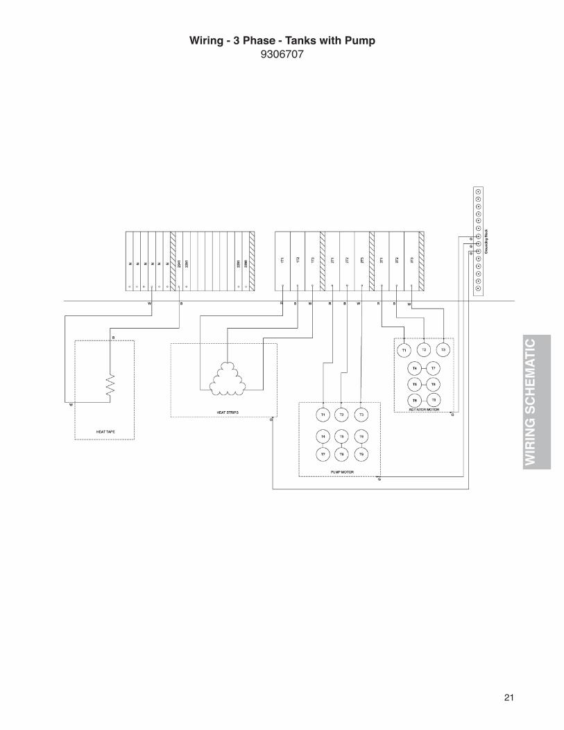
Electric HeatThe tank is heated with twelve electric heat strips. The heaters are located between the insulation and the bottom of the tank. There are three strips under each panel on the bottom of the tank. Each heat strip is 240V and 800 Watts. The heat strips are wired in single phase, where single phase is provided and three phase, where three phase is provided. A thermostat located in the control box controls them. A light in the control box door indicates when the heaters are on.
Float GaugeThe tank is equipped with a float type level gauge. A float is hung from a cable passing through the top of the tank. The cable runs over two pulleys and down the side of the tank to an indicator weight. The white line on the indicator weight aligns with the number on the scale to determine the amount of liquid in the tank.
WARNING
The agitator is controlled by a timer and may start unexpectedly. Stay clear.
AgitatorThe tank is equipped with an agitator to mix the contents of the tank. The agitator is a propeller supported on a vertical shaft inside the tank. The propeller shaft is supported by a bushing at the bottom and a ball bearing at the top. The height of the propeller from the bottom of the tank is adjustable. The agitator is driven by a one horse power, 115 volt motor. This motor is located at the top of the tank. The motor drives the agitator through a gear box and a belt drive, to reduce the speed. The agitator is controlled by an electronic timer, located in the control box. The timer may be programmed to turn the agitator on and off at 8 selected times.

7CONTROL BOX - Tanks with Pump
Control BoxThe control box is located at the left front corner of the storage tank frame. In the door of the control box is a master disconnect or switch which controls power for all of the electrical functions. A heater indicator light is also located in the door, indicating when the heaters are on. On tanks with pumps, a pump, forward, off and reverse switch will be located in the control box door as well. Inside the box are the various fuses and contactors to operate the electrical equipment. A timer for the agitator and a thermostat for the heaters is also located inside the control box. On the right side of the control box is a 115 volt receptacle (GFI), that may be used for powering lights or hand tools up to 15 amp capacity.
WARNING
Turn main power off at control panel before making repairs or adjustments.
CONTROL BOX - Gravity Tanks

8
Tank with Pump
Loading/Unloading Line From Pump
Pump Pump Drive Motor
Thermometer
3" Fill Line
Check Valve
Ball Valve
Ball Valve
ThermometerA dial thermometer is located in a dry well in the side of the tank. The thermometer indicates the temperature of the asphalt in the tank. The thermometer may be removed from the well with asphalt in the tank.
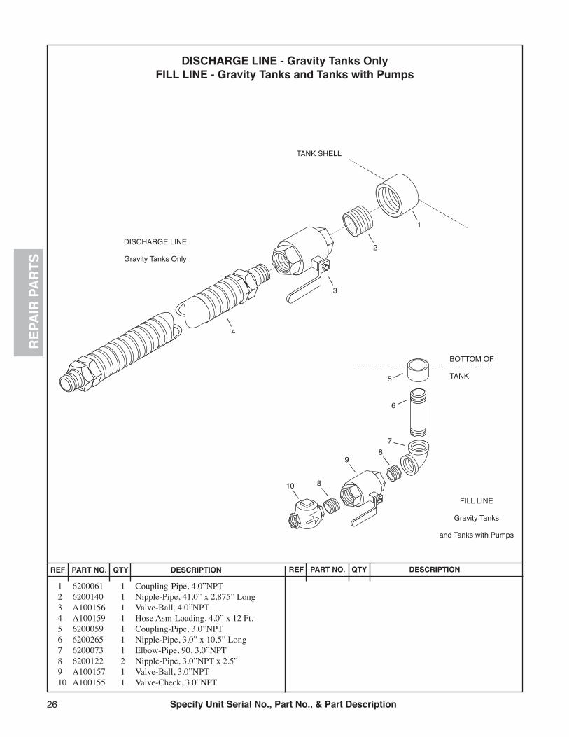
Plumbing (Gravity Tanks)A four inch diameter line in the side of the tank is used to load other small tanks from the storage tank. A lever operated ball valve is located in this line. A four inch by 12 foot loading hose is provided. A three inch line at the bottom of the tank is used for unloading transport tanks into the storage tank. A lever operated ball valve, and a check valve are located in this line. Both of these lines are insulated and heated with 115 volt heat tape. The heat tape is on whenever the master switch in the control panel door is on.
Thermometer
BallValve
3" Fill(Loading) Line Check Valve
4" Discharge Ball Valve4" Unloading (Discharge) Line
Gravity Storage Tank
Plumbing (Pump Tanks)A three inch diameter line runs from the bottom of the tank to the pump. A lever operated ball valve is located in this line. The pump is belt driven by a ten horsepower, 240 volt electric motor. It may be used to pump out of the storage tank (forward) into other small tanks, or used to pump (reverse) into the storage tank from a transport tank. A three inch by 12 foot loading hose is provided. Another three inch line, from the bottom of the tank may be used for loading the storage tank from a trans-port tank. A lever operated ball valve and a check valve are located in this line. Both of these lines are insulated and heated with 115 volt heat tape. The heat tape is on whenever the master switch in the control panel door is on.

9
Safety InstructionsSafety warnings have been provided to call attention to any potentially hazardous situation that may cause property damage, personal injury or death to the operator or bystanders. These safety warnings are identified by the following warning symbols:
DANGER - Alerts you to immediate hazards which will result in severe personal injury or death.
WARNING - Alerts you to hazards which may cause severe personal injury or death.
CAUTION - Hazards or unsafe practices which could result in minor personal injury or product or property damage.
NOTE - Provides general information that the operator should be aware of when performing an operation.
All of these warnings appear throughout the manual.As with any type of equipment, there are certain hazards associated with improper or careless operation. The ability to read and understand the instructions in this manual should be a required qualification to become an operator.
Hot SurfacesSince this tank is intended to store hot liquid asphalt, the surfaces of the tank and equipment may be hot. All surfaces and equipment should be considered to be hot. Wear insulated gloves and protective clothing to prevent burns. The piping is heated with electric heat tape, it will be hot even though it has not been used recently.
Hot LiquidsThe liquids stored in this tank are hot. The piping and hoses used to transfer the liquids are hot. Wear insulated gloves, protective clothing and a face shield when transferring hot liquids, or handling hot liquid hoses to avoid burns. Stay clear of piping that may contain hot liquids. Leave all valves closed (with handles at right angles to the valve), unless you are performing an operation which requires a valve to be opened. Do not open valves unless you are prepared for asphalt to flow.
Electrical ShockThis equipment is powered by high voltage electricity. To avoid electrical shock causing personal injury or death, do not attempt to make repairs or adjustments without turning the main power off at the control panel. Do not attempt to operate this equipment with the control panel door open.
Moving PartsThis equipment contains moving parts, turning shafts, pulleys and belts. Keep all guards in place when operating. The agitator is controlled by a timer and may start unexpectedly. To avoid entanglement, do not attempt to make repairs or adjustments without turning the main power off at the control panel.
FallsTo avoid falls that could result in death or serious injury, do not climb over the guard rails on top of the tank for any reason. Be careful when working on top of the tank to avoid dropping tools or parts that could strike somone on the ground.
Tank EntranceTo avoid unauthorized entrance to the tank, keep the hinged door on top of the tank locked at all times.

10
IMPORTANT
When filling the storage tank for the first time, carefully fill until the material level raises to the top of the manhole collar. This will coat the interior of the tank with a thin film of asphalt that will deter corrosion.
Preparation For UseInspectionUnpack the ladder, ladder cage and handrail. Check for damage that may have occurred during shipment. Visually inspect the tank, particularly the tank jacket and insulation for damage that may have occurred during shipment. Report any damage to the driver delivering the tank.
Setting Tank in Place 1. Install ladder, ladder cage and hand rails before lifting tank to the upright position. Securely tighten all fasteners.
2. The tank level gauge float has been secured to the roof of the tank for shipment. Free the float from the roof before lifting the tank to the upright position. Slide the float down the guide cable to the bottom of the tank.
3. All nine tank legs must be fully welded to steel foundation pads, with at least 1/4 inch fillet welds, all the way around each leg. Foundation pads must be securely anchored to the concrete foundation.
CAUTION
Do not stand the storage tank upright without being prepared to weld the legs immediately. High winds can overturn a tank which has not been properly anchored.
WARNING
To avoid falls that could result in death or serious injury, do not climb over the guard rails on top of the tank for any reason.
Keep all guards in place when operating.
Connecting Power
220 volt single phase power is required for gravity tanks. 240 volt three phase power, with a neutral wire is required for tanks with pumps. Power connection and wiring should be done by a qualfied electrician, to conform to local and national electric codes.
Start Up Rotating DevicesTurn the agitator on and observe the rotation of the shaft and propeller inside the tank. The direction should match the diagram below. If it does not, cor-rections to the wiring must be made. On tanks with pumps, turn the pump to forward momentarily, and observe the direction of rotation of the pulleys. The direction should match the diagram below. If it does not, corrections to the wiring must be made.
DANGER
This equipment is powered by high voltage electricity.
Forward
Pump outForward
Agitator RotationReverse
Pump InReverse
Check for proper rotation of agitator and pump motor
WARNING
The agitator is controlled by a timer and may start unexpectedly. Stay Clear.

11
General Operating InstructionsHeater Operation 1. Do not operate the heaters unless there is at least 150 gallons of asphalt in the tank.
2. Turn the master power switch off and open the control box door.
3. Set the desired temperature on thethermostat knob.
4. Close the control box door and turn the master power switch on.
5. The heaters will turn on and off automatically to maintain the set temperature.
6. The indicator light on the control box door will turn on whenever the heaters are on.
Agitator Operation 1. Do not run the agitator when the tank is empty. The lower bearing is lubricated by the asphalt. Running the agitator without asphalt may cause damage to the bearing and shaft.
2. Do not run the agitator when there is less than the amount of asphalt shown in the following chart. Less than the amount shown below will expose the propeller blades, and cause splashing of the asphalt. Splashing of asphalt emulsions may cause them to separate.
WARNING
This equipment is powered by high voltage electricity. Turn main power off at control panel before making repairs or adjustments.
WARNING
All surfaces and equipment should be considered to be hot. Wear insulated gloves and protective clothing to prevent burns.
Minimum Amount of Asphalt in Tank for Agitation
NominalTank Capacity Minimum Amount 2000 gallon 400 gallon 3000 gallon 720 gallon 4000 gallon 840 gallon 5000 gallon 950 gallon 6000 gallon 1020 gallon 7000 gallon 1200 gallon
3. The agitator may be run continuously by turning it on with a switch on the timer, or set to turn on and off at certain times of the day and days of the week by programming the timer. The master power switch on the door of the control box must be on to run the agitator. Follow the timer programming instructions below for timed operation.
WARNING
The agitator is controlled by a timer and may start unexpectedly. Stay Clear.
WARNING
Keep all guards in place when operating.

12
#6 To switch the override OFF- slide mode switch to “0”.- the switch remains off indefinitely (circuit open).
#7 Skip cycle- in automatic run mode, press the “X >” button, the next program is skipped.
#8 Setting error- If “EEE” appears, a setting error exists. The switch cycle number in error is shown. Slide set switch to “p”. Press button until cycle is shown. Review this and the following setting to correct error. Slide set switch to “RUN”.
#9 Clear any setting- slide the “RUN” switch to “P”, press the lower “P” button to show switch cycle you want to clear.- press 1....7 button until no days are indicated. Repeat for the following switch cycle. This on/off cycle is now inactive.
#10 Clear all- To erase all settings, press “R”.
Timer Programming Instructions
#1 Setting the current time and current day- slide “RUN” switch to left symbol of clock face.- press 1....7 button until arrow points to current day (1=Monday, 2=Tuesday, etc.). Press “h” then “m” buttons to set the current time. The “PM” indicator shows noon to 11:59 p.m,- slide “RUN” switch to “run”. The clock colon will blink between the hours and minutes.
#2 Setting each cycle to “switch on”- slide the “RUN” switch to “P”; a “1” indicates this is the first switch cycle and a “bulb” icon indicates a switch-on condition (circuit closes). (Hint: odd numbers indicate a “switch-on” cycle.)- press 1....7 button until arrows point to selected day(s) you want this ON cycle to occur.- press “h” and “m” buttons to show switch-on time, noting the “PM” indicator.
#3 Setting each cycle to “switch off”- slide “RUN” switch to “P”. Press “p” button, note that switch cycle number changes to 2 and bulb blinks, indicating switch-off (circuit opens). (Hint: even numbers indicate a “switch-off” cycle).- press 1...7 button until arrows point to selected day(s) you want this OFF cycle to occur.- press “h” and “m” button to select switch-off time.
#4 Autorun mode- set time and day and desired switch cycles.- slide set switch to “RUN” and mode switch to “AUTO”. Switching will begin with the next switch-on set time.
#5 To switch the override ON- slide mode switch to “I”.- the switch remains on indefinitely (circuit closed).

13
Gravity Tank Operating Instructions
Filling Gravity Storage Tanks From Transport 1. Connect the transport tanker’s hose to the outlet line on the transport tanker.
2. Connect the hose from the transport tanker to the 3 inch fill line on the storage tank.
3. Open the valve on the storage tank and on the transport tanker.
4. Start the pump on the transport tanker to pump into the storage tank.
5. Watch the tank level gauge on the storage tank to protect against over filling the storage tank.
6. When filling is complete, stop the pump on the transport tanker.
7. Clean the hoses are directed by the transport tanker operating instructions.
8. Close the valves on the storage tank and on the transport tanker.
9. Disconnect the hose from the storage tank.
WARNING
All surfaces and equipment should be considered to be hot.
WARNING
The liquids stored in this tank are hot. Wear gloves and protective clothing whentransferring or handling hoses.
WARNING
Do not open valves unless you are prepared for asphalt to flow. The Liquids stored in this tank are hot.
3.Open
1. Closed
Open
Closed
FILL storage tank
Gravity Storage Tank
14
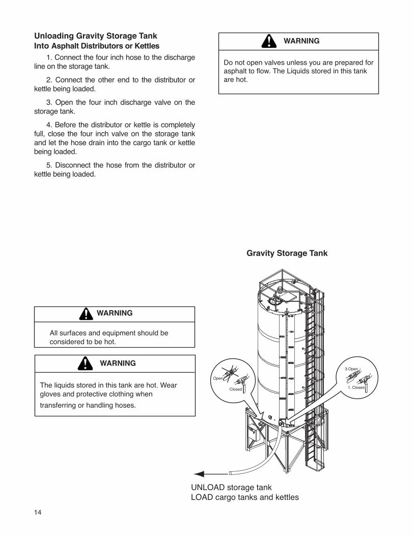
Unloading Gravity Storage TankInto Asphalt Distributors or Kettles 1. Connect the four inch hose to the discharge line on the storage tank.
2. Connect the other end to the distributor or kettle being loaded.
3. Open the four inch discharge valve on the storage tank.
4. Before the distributor or kettle is completely full, close the four inch valve on the storage tank and let the hose drain into the cargo tank or kettle being loaded.
5. Disconnect the hose from the distributor or kettle being loaded.
WARNING
All surfaces and equipment should be considered to be hot.
WARNING
The liquids stored in this tank are hot. Wear gloves and protective clothing whentransferring or handling hoses.
WARNING
Do not open valves unless you are prepared for asphalt to flow. The Liquids stored in this tankare hot.
UNLOAD storage tankLOAD cargo tanks and kettles
3.Open
1. Closed
Open
Closed
Gravity Storage Tank

15
Pump Tank Operating Instructions
Filling Storage Tanks With PumpsFrom Transport Tanker 1. Connect the transport’s hose to the outlet line on the transport tanker.
2. Connect the hose from the transport tanker to the 3 inch fill line on the storage tank.
3. Open the valve on the storage tank and on the transport tanker.
4. Start the pump on the transport tanker to pump into the storage tank.
5. Watch the tank level gauge on the storage tank to protect against over filling the storage tank.
6. When filling is complete, stop the pump on the transport tanker.
7. Clean the hoses are directed by the transport tanker operating instructions.
8. Close the valves on the storage tank and on the transport tanker.
9. Disconnect the hose from the storage tank.
WARNING
All surfaces and equipment should be considered to be hot.
WARNING
The liquids stored in this tank are hot. Wear gloves and protective clothing whentransferring or handling hoses.
WARNING
Do not open valves unless you are prepared for asphalt to flow. The Liquids stored in this tankare hot.
3.Open
1. Closed
Open
Closed
FILL storage tank withpump or transport tank
Storage Tank with Pump
16
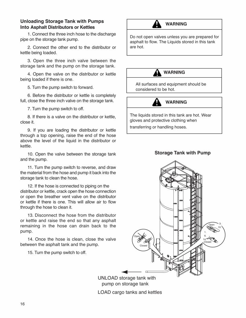
Unloading Storage Tank with PumpsInto Asphalt Distributors or Kettles 1. Connect the three inch hose to the discharge pipe on the storage tank pump.
2. Connect the other end to the distributor or kettle being loaded.
3. Open the three inch valve between the storage tank and the pump on the storage tank.
4. Open the valve on the distributor or kettle being loaded if there is one.
5. Turn the pump switch to forward.
6. Before the distributor or kettle is completely full, close the three inch valve on the storage tank.
7. Turn the pump switch to off.
8. If there is a valve on the distributor or kettle, close it.
9. If you are loading the distributor or kettle through a top opening, raise the end of the hose above the level of the liquid in the distributor or kettle.
10. Open the valve between the storage tank and the pump.
11. Turn the pump switch to reverse, and draw the material from the hose and pump it back into the storage tank to clean the hose.
12. If the hose is connected to piping on thedistributor or kettle, crack open the hose connection or open the breather vent valve on the distributor or kettle if there is one. This will allow air to flow through the hose to clean it.
13. Disconnect the hose from the distributor or kettle and raise the end so that any asphalt remaining in the hose can drain back to the pump.
14. Once the hose is clean, close the valve between the asphalt tank and the pump.
15. Turn the pump switch to off.
WARNING
All surfaces and equipment should be considered to be hot.
WARNING
The liquids stored in this tank are hot. Wear gloves and protective clothing whentransferring or handling hoses.
WARNING
Do not open valves unless you are prepared for asphalt to flow. The Liquids stored in this tankare hot.
Open
Closed
Open
Closed
UNLOAD storage tank with pump on storage tankLOAD cargo tanks and kettles
3.10. 3.10.
1. 6.14.
Storage Tank with Pump

17
Cleaning Asphalt Pump 1. With the hose connected to the pumpdischarge pipe, put the loose end of the hose in a bucket.
2. Check the area for sources of flame, lit cigarettes, torches or lighters. Extinguish all sources of flame.
3. Put the end of the small hose attached to the breather vent valve in a bucket of diesel fuel or kerosene.
4. Hold the hoses to avoid being splashed.
5. While holding the hoses securely, turn the pump switch to forward momentarily. This will draw the solvent from the bucket, pump it through the pump and out into the other bucket.
6. Turn the pump switch to off.
7. Drain the remaining solvent from the three inch hose into the bucket.
WARNING
Extinguish all sources of flame,lit cigarettes, torches or lighters
WARNING
All surfaces and equipment should be considered to be hot. Wear insulated gloves and protective clothing to prevent burns.
WARNING
Do not open valves unless you are prepared for asphalt to flow. The Liquids stored in this tankare hot.
Open
Closed
Open
Closed
Storage Tank with Pump

18
WIR
ING
SC
HEM
ATIC
Wiring - Single Phase - Gravity Tanks9306643

19
WIR
ING
SC
HEM
ATIC
Wiring - 3 Phase - Gravity Tanks9306702
20
WIR
ING
SC
HEM
ATIC
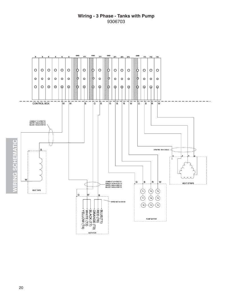
Wiring - 3 Phase - Tanks with Pump9306703
21
WIR
ING
SC
HEM
ATIC
Wiring - 3 Phase - Tanks with Pump9306707

Specify Unit Serial No., Part No., & Part Description22
REP
AIR
PA
RTS
1
5
9
9
9
9
9
910
11
12
13
13
18
21
22
16
23
23
25
24
24
19
2017
15
2
37 6
4,8
4,8
4,84,84,8
483
3
3
3
2
2
Ladder, Handrails, Heaters, Tank Trim & Insulation
Size Model Number of Rungs7000 gal. Gravity 276000 gal Gravity 247000 gal Pump Units 236000 gal Pump Units 204000 gal Gravity 192000 gal Gravity 183000 gal Gravity 174000 gal Pump Units 15
A1001LA Ladder Assembly
REF PART NO. QTY DESCRIPTION REF PART NO. QTY DESCRIPTION
1 5200388 1 Handrail Assembly2 5200414 3 Lifting Attachment3 5200179 5 Plate-Handrail Mount4 5200413 6 Brace-Ladder5 5200410 6 Bracket, Ladder Brace, 4.50” Wide6 12 Washer-Lock, 0.50”7 12 Nut-Hex, 0.50”NC8 5200409 6 Bracket-Ladder Brace, 4.0” Wide9 5200134 AR Bracket-Cage to Ladder
10 A1001LC 1 Walkway-Storage Tank11 A1001LA 1 Ladder Asm-Storage Tank (Specify Storage Tank Size & Model)12 A1001LJ 1 Cape-Top Section, 3 Hoop (Specify Storage Tank Size & Model)13 5200135 17 Clip-Cage
14 A1001LG 2 Cage-Intermediate Section, 7 Bar15 A1001LF 1 Cage-Bottom Section, 3 Bar16 5200516 1 Guard-Toe, Storage Tank17 5200517 1 Guard-Toe, Storage Tank18 5200515 1 Guard-Toe, Storage Tank19 5200518 29 Spacer-Toe Guard, Storage Tank20 5200488 1 Shipping Leg-Storage Tank, LH21 5200489 1 Shipping Leg-Storage Tank, RH22 0122408 12 Screw-Hex, 0.50”NC x 1.0” Long23 6319107 AR Aluminum Sheeting24 6000753 AR Insulation-Fiberglass, 2.0” Thick25 A107602 12 Heater-Strip, 240V, 800Watt
AR = As Required
23Specify Unit Serial No., Part No., & Part Description
REP
AIR
PA
RTS
REF PART NO. QTY DESCRIPTION REF PART NO. QTY DESCRIPTION
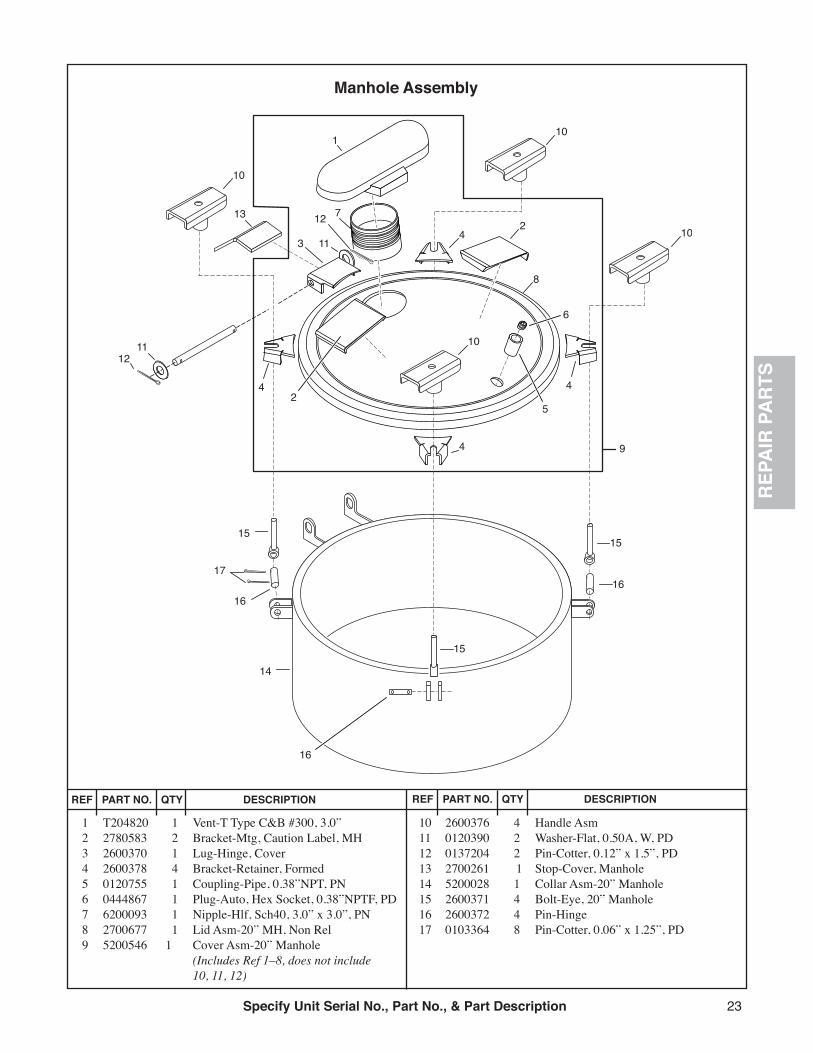
1 T204820 1 Vent-T Type C&B #300, 3.0”2 2780583 2 Bracket-Mtg, Caution Label, MH3 2600370 1 Lug-Hinge, Cover4 2600378 4 Bracket-Retainer, Formed5 0120755 1 Coupling-Pipe, 0.38”NPT, PN6 0444867 1 Plug-Auto, Hex Socket, 0.38”NPTF, PD7 6200093 1 Nipple-Hlf, Sch40, 3.0” x 3.0”, PN8 2700677 1 Lid Asm-20” MH, Non Rel9 5200546 1 Cover Asm-20” Manhole (Includes Ref 1–8, does not include 10, 11, 12)
10 2600376 4 Handle Asm11 0120390 2 Washer-Flat, 0.50A, W, PD12 0137204 2 Pin-Cotter, 0.12” x 1.5”, PD13 2700261 1 Stop-Cover, Manhole14 5200028 1 Collar Asm-20” Manhole15 2600371 4 Bolt-Eye, 20” Manhole16 2600372 4 Pin-Hinge17 0103364 8 Pin-Cotter, 0.06” x 1.25”, PD
1
1211
13
9
3 11
12 7 2
10
10
10
14
15
17
16
15
16
16
15
10
8
4
4
4
4
25
6
Manhole Assembly

Specify Unit Serial No., Part No., & Part Description24
REP
AIR
PA
RTS
1 0120426 2 Screw-Hex, 0.50”NC x 1.25”2 A100161 2 Pulley-1.5” OD x 7/16” x 1/2 Bore3 9411727 2 Nut-Hex, Lock, 0.50”NC4 A1001PL 2 Bracket-Mounting, Pulley5 0274993 6 Nut-Hex, Lock, 0.38”NC6 A1001PK 2 Ear-Keeper, Cable7 0120388 4 Washer-Flat, 0.38”8 A1001PW 2 Screw-Drilled, 0.38”NC x 1.0”9 A100162 AR Cable-3/16” OD, Plastic Coated
10 6000338 AR Cable-1/16” Diameter11 A1001PJ 1 Float Assembly-12”12 A1001PM 1 Counterweight-2.0” x 6.0” Long13 A1001PN 1 Channel-Trap, Counterweight14 A1001GA AR Scale Asm-U.S., 4000 Gallon Units A1001GB AR Scale Asm-U.S., 6000 Gallon Units A1001GC AR Scale Asm-U.S., 7000 Gallon Units A1001GD AR Scale Asm-U.S., 3000 Gallon Units A1001GE AR Scale Asm-U.S., 2000 Gallon Units
REF PART NO. QTY DESCRIPTION REF PART NO. QTY DESCRIPTION
15 A1001GF AR Scale Asm-Metric, 2000 Gallon Units A1001GG AR Scale Asm-Metric, 3000 Gallon Units A1001GH AR Scale Asm-Metric, 4000 Gallon Units A1001GJ AR Scale Asm-Metric, 6000 Gallon Units A1001GK AR Scale Asm-Metric, 7000 Gallon Units16 6500038 1 Thermometer-5” Dial (Gravity Units) 6500039 1 Thermometer-2” Dial (Units w/ Pump)17 0144034 1 Bushing-Pipe, 0.75” x 0.50” (Gravity Units) 0144033 1 Bushing-Pipe, 0.75” x 0.25” (Units w/ Pump)
AR = As Required
Scale Assembly & Thermometer
1
4
2
2
3
4
5
56 7 8
14
15
16
17
67
8
10
12
139
11
3

25Specify Unit Serial No., Part No., & Part Description
REP
AIR
PA
RTS
5
6
7
1
3
12
8
3
911
4
9
13
10
Sample Valve
1 3410050 1 Pipe-Sch40, 0.75”NPT x 12.0”2 0144071 1 Coupling-Pipe, 0.75”NPT3 2780018 1 Well Asm-REcess, Sample Valve4 2700161 1 Ring-Finish, Sample Valve Outlet 2700162 1 Gasket-Sample Valve Outlet5 6600349 1 Valve-0.75”, Angle, Crane #26 0140798 1 Elbow-Pipe, 45, ST, 0.75”NPT7 6200433 1 Nipple-Pipe, Sch40, 0.75”NPT x 8.0”8 2780018 1 Cap Asm-Sampling Valve9 6000434 7 Rivet-Dr, 0.19, 0.12Grip, 0.17Max
10 6000346 6” Chain-PRF Coil,1911 2780027 1 Clip-Sealing Valve12 3390531 1 Tag-Warning, Sample Valve13 6100139 2 Rivet-Pop, 0.12”Dia x 0.18” Long
REF PART NO. QTY DESCRIPTION REF PART NO. QTY DESCRIPTION
Specify Unit Serial No., Part No., & Part Description26
REP
AIR
PA
RTS
DISCHARGE LINE - Gravity Tanks OnlyFILL LINE - Gravity Tanks and Tanks with Pumps
1 6200061 1 Coupling-Pipe, 4.0”NPT2 6200140 1 Nipple-Pipe, 41.0” x 2.875” Long3 A100156 1 Valve-Ball, 4.0”NPT4 A100159 1 Hose Asm-Loading, 4.0” x 12 Ft.5 6200059 1 Coupling-Pipe, 3.0”NPT6 6200265 1 Nipple-Pipe, 3.0” x 10.5” Long7 6200073 1 Elbow-Pipe, 90, 3.0”NPT8 6200122 2 Nipple-Pipe, 3.0”NPT x 2.5”9 A100157 1 Valve-Ball, 3.0”NPT10 A100155 1 Valve-Check, 3.0”NPT
REF PART NO. QTY DESCRIPTION REF PART NO. QTY DESCRIPTION
BOTTOM OF
TANK
TANK SHELL
FILL LINE
Gravity Tanks
and Tanks with Pumps
DISCHARGE LINE
Gravity Tanks Only
1
2
3
4
5
6
78
9
810

27Specify Unit Serial No., Part No., & Part Description
REP
AIR
PA
RTS
Bottom of Tank1
2
34
56
78
1211
21 22 23
26
2728
29
31
3538 39 36
4042
4344
19
46
48
45471415
16
41
37
3432, 33
30
24, 25109 13
14
15
16 18 2019
16
17
NOTE: See "BituminousPump P-200" forP-200 Pump parts
Pump Unit Assembly
1 6200132 1 Nipple-Pipe, 3.0”NPT x 8.0” Long2 6200073 1 Elbow-Pipe, 90, 3.0”NPT3 A1001PP 1 Nipple-Victaulic, 3.0”NPT x 8.0” Long4 6600156 1 Coupling-Victaulic5 A1001PH 1 Nipple-Victaulic, 3.0” x 4.5”6 A100157 1 Valve-Butterfly, 3.0”7 6200121 1 Nipple-Pipe8 A1001PY 1 Elbow-Pipe, ST, 90, 3.0”NPT, Tapped9 0121209 1 Nipple-Pipe, 0.25” x 3.0”
10 6600303 1 Valve-Gate,0.25”11 6600305 1 Hose End-0.25MP x 3/8T12 6600324 1 Hose-3/8”ID, Rubber, 2 Ft. Long13 0428217 4 Screw-Hex, 5/8”NC x 1.5”14 0121574 8 Washer-Lock, 5/8”15 3340358 2 Coupling Asm-Flange16 3340341 3 Gasket-Mounting, Pump17 3340593 1 Pump Asm, Bituminous, P-20018 6000712 1 Key-0.5” Sq. x 3.5”19 0120378 8 Nut-Hex, 0.5”NC20 0120384 4 Washer-Lock, 0.5”21 A1001PC 1 Channel-Support, Bearing22 6420114 1 Bearing-Pump Shaft23 0122459 4 Screw-Hex, 0.5” x 2.0”24 A100153 1 Sheave-Pump, 18.4”25 A100154 1 Bearing-Pump Sheave26 6435040 2 Belt-V, B7527 A1001QA 2 End Cover Guard, Inside28 A1001PV 1 Belt Guard
29 A1001PE 2 Bracket-Support, Belt Guard30 0120375 4 Nut-Hex, 0.25”NC31 0120380 4 Washer-Lock, 0.25”32 A100151 1 Sheave-Motor, 4.8”33 A100152 1 Bushing-Motor Sheave34 3361156 1 Key-5/16 Sq x 2.0”35 0122307 4 Screw-Hex, 7/16”NC x 2.0”36 A1001PF 2 Bracket-Support, Guard37 0121900 4 Screw-Hex, 0.25”NC x 1.0”38 4050188 2 Bolt-Draw, Motor39 4050185 2 Brace-Draw Bolt40 A1001PB 2 Side Channel-Pump Base41 6700970 1 Connector- 1/2 Sealtite A100107 3 Wire Nut-10 ga A100111 6’ Wire-White, 10 ga, Strand A100109 6’ Wire-Red, 110 ga, Strand A100110 6’ Wire-Black, 10 ga, Strand 6700710 6’ Sealtite Conduit, 0.5”42 A100150 1 Motor-Electric, 10HP, 240V, 3 Phase 6703193 1 Motor-Elec., 10HP, 220V, Single Phase (OPTIONAL)
43 0120389 4 Washer-Flat, 7/16”44 9413947 4 Nut-Hex, 7/16”NC, Lock45 6200084 1 Elbow-Pipe, 90, ST, 3.0”46 6200134 1 Nipple-Pipe, 3.0”NPT x 9.0”47 0428691 4 Screw-Hex, 5/8”NC x 2.0”48 A1001PA 1 Base-Pump/Motor
REF PART NO. QTY DESCRIPTION REF PART NO. QTY DESCRIPTION

Specify Unit Serial No., Part No., & Part Description28
REP
AIR
PA
RTS
1
23456
8
7
9
10
1112
14
15
17
18
22 2324
2526 27 28
2627
20
18
16
19
2114
13
13
Bituminous Pump P-200
1 3340342 1 Valve Asm-Bypass (Includes Ref 2–12)2 3340350 1 Cap3 3340349 1 Gasket4 3340348 1 Bolt-Adjusting5 02715011 1 Nut-Hex, 7/16”6 6600264 1 Gasket7 3340347 1 Plug8 6600208 1 Gasket9 3340346 1 Bearing-Spring
10 3340345 1 Spring11 3340344 1 Valve Body12 3340343 1 Plate-Face, Bypass Valve13 3340314 3 Bearing14 3340573 2 Gasket
15 3340331 1 Case16 3340334 1 Impeller17 3340335 1 Impeller18 6000469 2 Key-0.375” x 5.0”19 3340337 1 Shaft20 3340340 1 Shaft-Drive21 6000468 1 Key-0.375” x 1.875”22 3340312 1 Plate-Face23 3340294 1 Sleeve-Wearing24 6600310 1 Packing25 3340307 1 Gland26 3340308 2 Clip27 3340949 2 Stud-Packing Gland28 0124843 2 Nut-Hex, Jam, 0.56”NC
REF PART NO. QTY DESCRIPTION REF PART NO. QTY DESCRIPTION

29Specify Unit Serial No., Part No., & Part Description
REP
AIR
PA
RTS
Agitator Assembly
1 0122408 12 Screw-Hex, 0.50”NC x 1.0”2 9411417 12 Washer-Flat, 0.50”3 A1001AG 1 Guard-Agitator Drive4 A1001AD 1 Motor Base-Agitator5 A100175 1 Motor-Electric, 1HP, 115V, Single Phase6 A100190 1 Gearbox-7.63 : 1, 56 C Face, 1HP7 0120233 4 Screw-Hex, 0.38”NC, 1.0”8 A100176 1 Sheave-3.0” Dia, 0.875” Bore9 A100178 1 Sheave-18.0” Dia.10 A100179 1 Bushing-Taper Lock, 1.50” Bore11 A100102 1 Belt-V, BX7012 A1001AF 1 Shaft-Upper, Agitator13 6420114 1 Bearing-Flange, 4 Bolt, 1.5” Shaft
14 6310216 1 Plate-Top Bearing15 0120236 2 Screw-Hex, 0.50”NC x 2.75”, Gr216 9411727 4 Nut-Hex, Lock, 0.50”NC17 6303281 1 Tube-2.0” x 0.25 CDS, Ft (Specify Model & Capacity)18 A1001AC 1 Blade Asm-Agitator19 0120918 4 Screw-Hex, 0.38”NC x 1.5”, Gr220 0274993 4 Nut-Hex, Lock, 0.38”NC21 A1001AE 1 Shaft-Lower, Agitator22 6420063 1 Bushing-Bronze, 1.5” x 2.0” x 2.0”23 A1001AB 1 Bearing Asm-Agitator24 6310007 1 Channel-Bottom, Bearing25 0120426 2 Screw-Hex, 0.5”NC x 1.25”, Gr2
REF PART NO. QTY DESCRIPTION REF PART NO. QTY DESCRIPTION
Bottom of Tank
512
1
1
2
12
2
3
7
6
4
8
11
10
12
1213
1415
17
20
19
18
16
15
25
16
2223
24
16
21
9
16

30
Part No. Page No. Part No. Page No. Part No. Page No. Part No. Page No. Part No. Page No.0103364 220120233 280120236 280120375 260120378 260120380 260120384 260120388 230120389 260120390 220120426 230120426 280120755 220120918 280121209 260121574 260121900 260122307 260122408 210122408 280122459 260124843 270137204 220140798 240144033 230144034 230144071 2402715011 270274993 230274993 280428217 260428691 260444867 222600370 222600371 222600372 222600376 222600378 222700161 242700162 242700261 222700677 222780018 242780018 242780027 242780583 223340294 273340307 273340308 273340312 273340314 273340331 273340334 273340335 273340337 273340340 273340341 263340342 273340343 273340344 273340345 27
3340346 273340347 273340348 273340349 273340350 273340358 263340573 273340593 263340949 273361156 263390531 243410050 244050185 264050188 265200028 225200134 215200135 215200179 215200388 215200409 215200410 215200413 215200414 215200488 215200489 215200515 215200516 215200517 215200518 215200546 226000338 236000346 246000434 246000468 276000469 276000712 266000753 216100139 246200059 256200061 256200073 256200073 266200084 266200093 226200121 266200122 256200132 266200134 266200140 256200265 256200433 246303281 286310007 286310216 286319107 216420063 286420114 266420114 286435040 266500038 236500039 23
6600156 266600208 276600264 276600303 266600305 266600310 276600324 266600349 246700710 266700970 266703193 269411417 289411727 239411727 289413947 26A100102 28A100107 26A100109 26A100110 26A100111 26A100150 26A100151 26A100152 26A100153 26A100154 26A100155 25A100156 25A100157 25A100157 26A100159 25A100161 23A100162 23A100175 28A100176 28A100178 28A100179 28A1001AB 28A1001AC 28A1001AD 28A1001AE 28A1001AF 28A1001AG 28A1001GA 23A1001GB 23A1001GC 23A1001GD 23A1001GE 23A1001GF 23A1001GG 23A1001GH 23A1001GJ 23A1001GK 23A1001LA 21A1001LC 21A1001LF 21A1001LG 21A1001LJ 21A1001PA 26A1001PB 26A1001PC 26A1001PE 26
A1001PF 26A1001PH 26A1001PJ 23A1001PK 23A1001PL 23A1001PM 23A1001PN 23A1001PP 26A1001PV 26A1001PW 23A1001PY 26A1001QA 26A107602 21T204820 22
IND
EX

Something Wrong with this manual? Ifyoufindinaccurateorconfusinginformationinthismanual,orjusthaveasuggestionfor
improvement, please let us know.
Mail or FAX this form to us at: E. D. ETNYRE & CO. 1333 S. Daysville Rd.Oregon, Illinois 61061 • Fax: 800-521-1107 • www.etnyre.com Attn: Service Manager
Recommended changes from: _______________________________________
Address ______________________________________________
City, State, Zip ______________________________________________
Phone ______________________________________________
Date Sent ______________________________________________
Manual Number (upper right corner of front cover) ________________________________________________
Manual Title ______________________________________________________________________
Explain the problem in the space below. Page Reference Paragraph Figure Problem (please be specific)Number Number Number Number
K-525-01