aspen plus lab pharmaceutical plant design - gju.edu.jo · about aspenone and aspenplus ......
TRANSCRIPT
www.Abuelrub.comwww.Abuelrub.com
Aspen
Dr. Ziad Abuelrub
Aspen Plus LabPharmaceutical Plant Design

www.Abuelrub.com
OUTLINE
1. Introduction
2. Getting Started
3. Thermodynamic Models & Physical Properties
4. Pressure Changers
5. Heat Exchangers
6. Flowsheet Analysis
7. Reactors
8. Equilibrium Separation Column
2

www.Abuelrub.com
ABOUT ASPENONE AND ASPENPLUS®
• AspenPlus® is a computer package (or software) provided by a US based company called AspenTech.
• The company develops several software packages that are sold under the name AspenONEwhich includes applications for engineering, supply chain, and manufacturing.
• This course will focus mainly on AspenPlus®, which we will refer from now on as Aspen, since it is the core element of AspenONE Engineering.
• This software provides many excellent features for process simulation. The following is some important features:
– Best-in-class physical properties methods and data.
– Improved conceptual design workflow.
– Scalability for large and complex processes.
– State of the art column internals calculations for flooding and pressure drop.
– Rate-based distillation
– Modeling batch distillation in a rigorous manner.
– Polymer thermodynamics methods and data, rate-based polymerization reaction models, and a library of industrial process models.
3
www.Abuelrub.com
INTRODUCTION
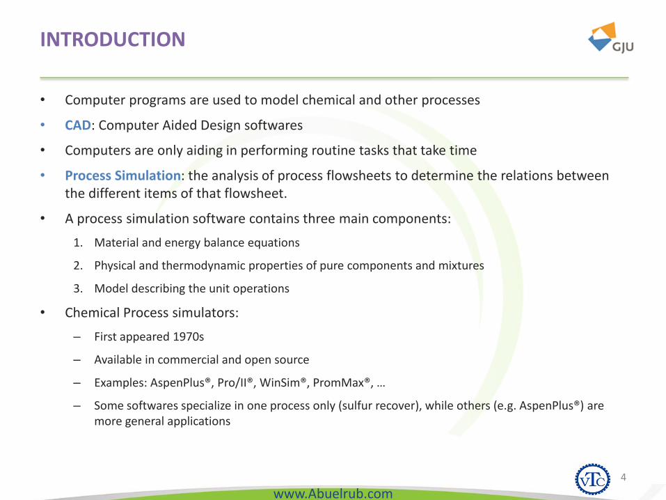
• Computer programs are used to model chemical and other processes
• CAD: Computer Aided Design softwares
• Computers are only aiding in performing routine tasks that take time
• Process Simulation: the analysis of process flowsheets to determine the relations between the different items of that flowsheet.
• A process simulation software contains three main components:
1. Material and energy balance equations
2. Physical and thermodynamic properties of pure components and mixtures
3. Model describing the unit operations
• Chemical Process simulators:
– First appeared 1970s
– Available in commercial and open source
– Examples: AspenPlus®, Pro/II®, WinSim®, PromMax®, …
– Some softwares specialize in one process only (sulfur recover), while others (e.g. AspenPlus®) are more general applications
4
www.Abuelrub.com
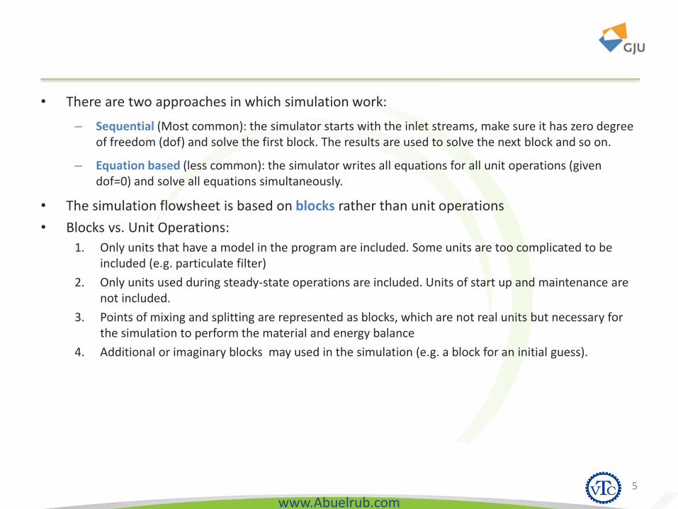
• There are two approaches in which simulation work:
– Sequential (Most common): the simulator starts with the inlet streams, make sure it has zero degree of freedom (dof) and solve the first block. The results are used to solve the next block and so on.
– Equation based (less common): the simulator writes all equations for all unit operations (given dof=0) and solve all equations simultaneously.
• The simulation flowsheet is based on blocks rather than unit operations
• Blocks vs. Unit Operations:
1. Only units that have a model in the program are included. Some units are too complicated to be included (e.g. particulate filter)
2. Only units used during steady-state operations are included. Units of start up and maintenance are not included.
3. Points of mixing and splitting are represented as blocks, which are not real units but necessary for the simulation to perform the material and energy balance
4. Additional or imaginary blocks may used in the simulation (e.g. a block for an initial guess).
5
www.Abuelrub.com6
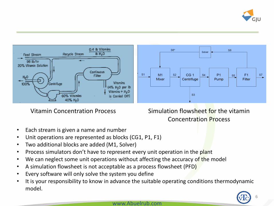
Vitamin Concentration Process Simulation flowsheet for the vitamin Concentration Process
• Each stream is given a name and number• Unit operations are represented as blocks (CG1, P1, F1)• Two additional blocks are added (M1, Solver)• Process simulators don’t have to represent every unit operation in the plant• We can neglect some unit operations without affecting the accuracy of the model• A simulation flowsheet is not acceptable as a process flowsheet (PFD)• Every software will only solve the system you define• It is your responsibility to know in advance the suitable operating conditions thermodynamic
model.

www.Abuelrub.com
OUTLINE
1. Introduction
2. Getting Started
3. Thermodynamic Models & Physical Properties
4. Pressure Changers
5. Heat Exchangers
6. Flowsheet Analysis
7. Reactors
8. Equilibrium Separation Column
7
www.Abuelrub.com
OBJECTIVES
• Learn how to access Aspen Plus
• Introduce the Aspen Plus interface
• Learn how to draw flowsheets and input data
• Learn how to run a simulation and view results
8

www.Abuelrub.com
ACCESSING ASPEN PLUS
from the Start Menu by going to AspenPlus V8.8> AspenPlus V8.8.
Or add the icon to the :desktop
9

www.Abuelrub.com
ACCESSING ASPEN PLUS
10
www.Abuelrub.com
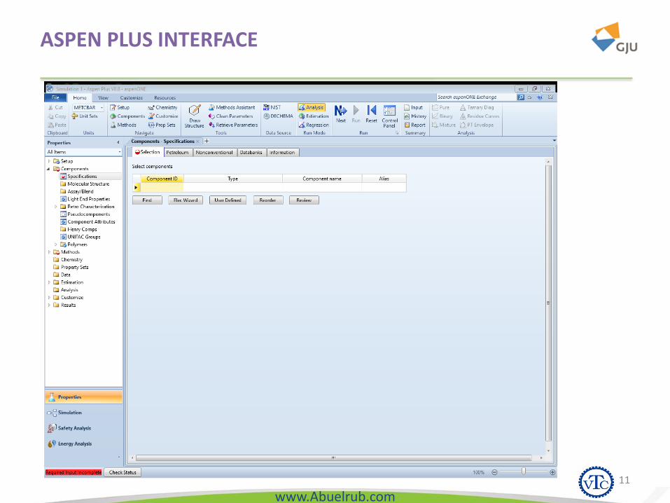
ASPEN PLUS INTERFACE
11

www.Abuelrub.com12

www.Abuelrub.com
1. MODEL LIBRARY
• This is where the unit operations are presented
• Divided into tabs
• Under each tab, there are several models (icons) present a certain type of that unit operation.
• Example:
– Reaction tab, Under which different models to calculate reaction products:
• Rstoic
• RYield
• REquil
• RGibbs
– RStoic model has icons given in the picture for reorientation purposes.
– You can switch between icons by Ctrl+K
13
www.Abuelrub.com
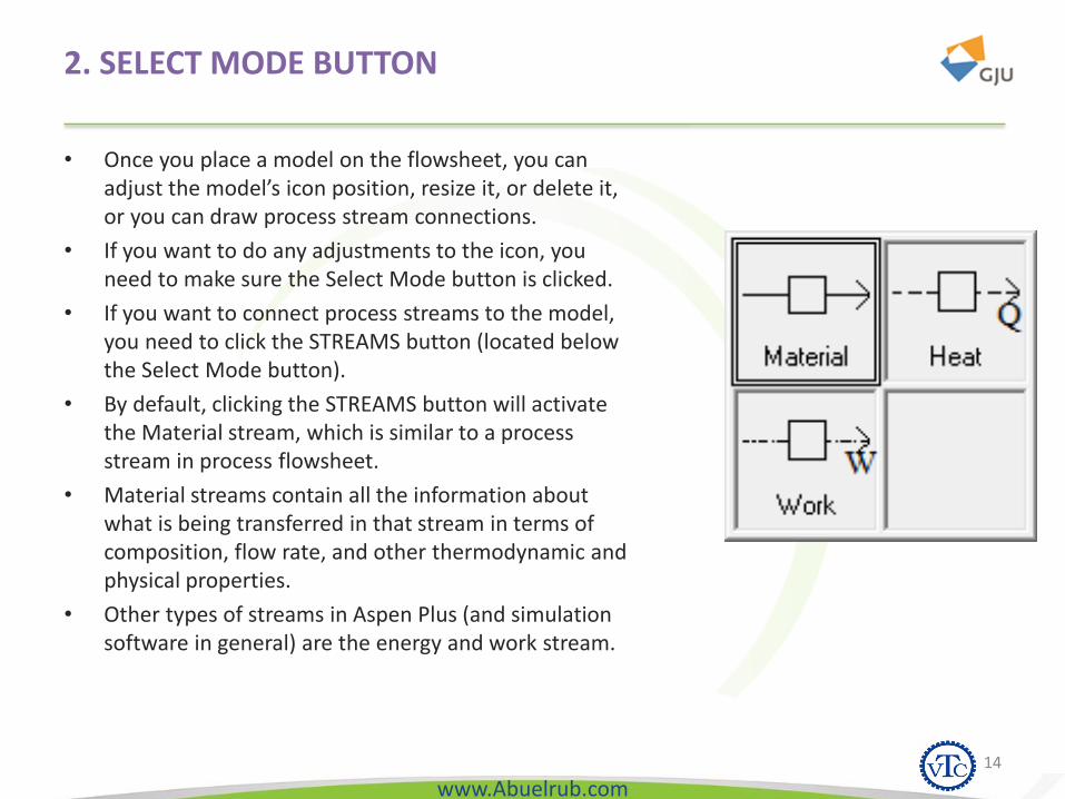
2. SELECT MODE BUTTON
• Once you place a model on the flowsheet, you can adjust the model’s icon position, resize it, or delete it, or you can draw process stream connections.
• If you want to do any adjustments to the icon, you need to make sure the Select Mode button is clicked.
• If you want to connect process streams to the model, you need to click the STREAMS button (located below the Select Mode button).
• By default, clicking the STREAMS button will activate the Material stream, which is similar to a process stream in process flowsheet.
• Material streams contain all the information about what is being transferred in that stream in terms of composition, flow rate, and other thermodynamic and physical properties.
• Other types of streams in Aspen Plus (and simulation software in general) are the energy and work stream.
14

www.Abuelrub.com
3. DATA BROWSER TOOLBAR
• The icons on this toolbar will open different pages of a window called Data Browser.
• The Data browser is where all the process information is input from the thermodynamic model used, the components, physical properties, streams information, units’ information, and others.
• The data browser is divided into folders, under each folder there are several sheets, and in each page there are several tabs. Within these tabs you can control all features of your simulation.
15
Data Browser
www.Abuelrub.com
4. SIMULATION RUN TOOLBAR
• Contains buttons that will allow you to run, pause, stop, and debug your simulation once you have completed the flowsheet creation.
• have different buttons activated/deactivated depending on the status of the flowsheet.
16

www.Abuelrub.com
5. FLOWSHEET STATUS BAR
• This is located at the lower right corner of the window and indicates the status of the flowsheet.
• When you start a flowsheet, the message shown will be “Flowsheet Not Complete”, indicating that there are missing streams that need to be connected.
• Once you make all necessary connections, the message will change to “Required Input Not Complete”, indicating that you have not specified all required inputs.
• There are several messages that will appear as you work with your simulation, but, in general, your ultimate goal is to get the “Results Present” message, indicating that the simulation was performed successfully.
17

www.Abuelrub.com
HELP
• Remember always to use the help provided with Aspen Plus when you are in doubt or when you are not sure how to perform certain tasks.
• The help can be accessed from the Help menu or via the Help button ().
18
www.Abuelrub.com
OUTLINE
1. Introduction
2. Getting Started
3. Thermodynamic Models & Physical Properties
4. Pressure Changers
5. Heat Exchangers
6. Flowsheet Analysis
7. Reactors
8. Equilibrium Separation Column
19

www.Abuelrub.com
INTRODUCTION
• Selecting the proper method for estimating properties is one of the most important steps that will affect the simulation.
• The estimation methods are stored in what is called a “Property Method”
• A property method is a collection of estimation methods to calculate several
– thermodynamic properties: fugacity, enthalpy, entropy, Gibbs free energy, and volume
– Transport properties : viscosity, thermal conductivity, diffusion coefficient, and surface tension
20

www.Abuelrub.com
PROPERTY METHOD SELECTION
• Property methods can be selected from the Data Browser, under the Properties folder
• Peng-Robinson, Soave-Redlich-Kwong, and Perturbed Chain methods are the most commonly used methods with hydrocarbon systems such as those involved in the oil and gas industries.
• When you select a property method, you are in effect selecting a number of estimation equations for the different properties.
21

www.Abuelrub.com
PENG-ROBINSON EQUATION
• For example, when you select the Peng-Robinson equation, you can see that the equation of state (EOS) selection is set to PENG-ROB which is given by:
22
• Where a, b, and c are component specific parameters.
• The values of these parameters are stored in Aspen Plus database for pure components or calculated using mixing rules for mixtures.
www.Abuelrub.com
DETERMINING HOW PROPERTIES ARE ESTIMATED
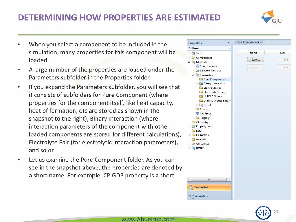
• When you select a component to be included in the simulation, many properties for this component will be loaded.
• A large number of the properties are loaded under the Parameters subfolder in the Properties folder.
• If you expand the Parameters subfolder, you will see that it consists of subfolders for Pure Component (where properties for the component itself, like heat capacity, heat of formation, etc are stored as shown in the snapshot to the right), Binary Interaction (where interaction parameters of the component with other loaded components are stored for different calculations), Electrolyte Pair (for electrolytic interaction parameters), and so on.
• Let us examine the Pure Component folder. As you can see in the snapshot above, the properties are denoted by a short name. For example, CPIGDP property is a short
23
www.Abuelrub.com
VIEW COMPONENT PROPERTIES
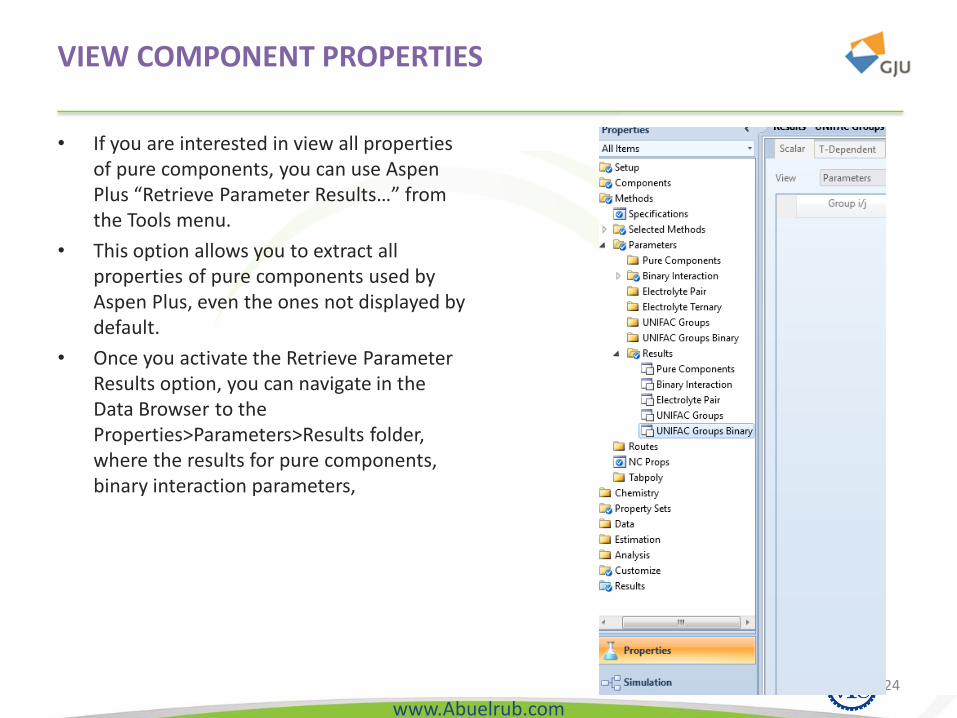
• If you are interested in view all properties of pure components, you can use Aspen Plus “Retrieve Parameter Results…” from the Tools menu.
• This option allows you to extract all properties of pure components used by Aspen Plus, even the ones not displayed by default.
• Once you activate the Retrieve Parameter Results option, you can navigate in the Data Browser to the Properties>Parameters>Results folder, where the results for pure components, binary interaction parameters,
24
www.Abuelrub.com
PHASE EQUILIBRIUM CALCULATIONS
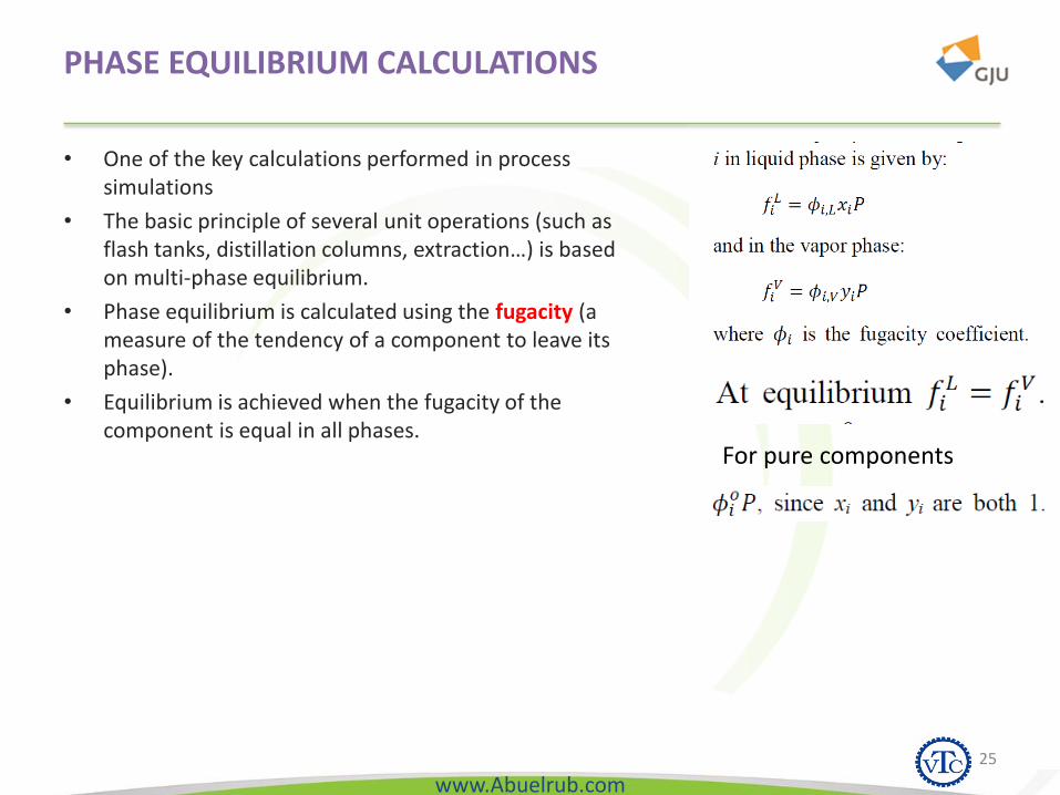
• One of the key calculations performed in process simulations
• The basic principle of several unit operations (such as flash tanks, distillation columns, extraction…) is based on multi-phase equilibrium.
• Phase equilibrium is calculated using the fugacity (a measure of the tendency of a component to leave its phase).
• Equilibrium is achieved when the fugacity of the component is equal in all phases.
25
For pure components
www.Abuelrub.com
FOUR SYSTEMS OF CALCULATING FUGACITIES1- IDEAL MODEL
• An ideal system is a system composed of ideal gases and liquids.
• And ideal gas follows the ideal gas law (PV = NRT) and has a fugacity of 1.
• An ideal liquid has an activity coefficient (γ) of 1.
• Ideal behavior can be assumed for vacuum/low pressure or very high temperature operations, for gases, and when very small interactions (or interactions that cancel each other) in liquids.
• In Aspen Plus, ideal behavior is modeled using the IDEAL property method.
• This method sets the activity coefficient for the liquid phase to 1, the EOS to the ideal gas law, and estimates the molar volume of liquids using the Rackett model.
• You can also use Henry’s law with the ideal model by designating relevant components as Henry’s components.
• As a general rule of thumb, when you have systems involving material such as water, organic acids, amines, alcohols, esters, ketones, aldehydes, and/or ethers, then you are dealing with polar molecules and there is a very good chance that the system deviates considerably from ideality. Think, for example, of water/alcohol mixtures.
26

www.Abuelrub.com
FOUR SYSTEMS OF CALCULATING FUGACITIES2- EQUATION OF STATE MODELS
• an equation of state (EOS) is a PVT relation used to predict thermodynamic properties.
• In Aspen Plus, there are several equations of state used for different applications, examples:
• the Peng-Robinson EOS (and its variations)
• the Soave-Redlich-Kwong EOS (and its variations), which belong to the cubic EOS.
• Other forms of EOS include those derived from statistical thermodynamics such as the Sanchez-Lacombe and SAFT.
• Another form of the EOS models is the steam tables (provided as a Base model in Aspen Plus).
27
www.Abuelrub.com
FOUR SYSTEMS OF CALCULATING FUGACITIES3- ACTIVITY COEFFICIENT MODELS
• For non-ideal liquid solutions, the fugacity of the components in the solution deviates from that of the pure component.
• The ratio of the fugacity in solution to that of pure component is defined as the activity:
𝑎𝑖 =𝑓𝑖𝑓𝑖𝑜
• The activity can be calculated from the activity coefficient (𝛾) as follows: 𝑎𝑖 = 𝛾𝑖,𝐿 ∙ 𝑥𝑖
• In general, the activity coefficient is greater than unity. What this means is that the fugacity of a component in mixture is higher than that of pure component. Thus, the same liquid will have higher tendency to vaporize when in mixture than in its pure state. This can be attributed to the increased repulsion between molecules with mixtures. In few cases, the activity coefficient will be less than unity, indicating increased attraction between molecules and less tendency to vaporize.
• In Aspen Plus, there are several activity coefficient models. Among the most commonly used is the
• NRTL, which can be applied to polar mixtures.
• Other models include: Wilson, Van Laar, UNIFAC, UNIQUAC, Flory Huggins, Electrolyte NRTL, and Scatchard Hildebrand models. In these models, the activity coefficient approach is used to calculate the liquid properties, while the vapor phase properties are calculated using an equation of state.
28

www.Abuelrub.com
FOUR SYSTEMS OF CALCULATING FUGACITIES4- OTHER MODELS
• There are still many other property models available through Aspen Plus.
• These models are classified as “Vapor Pressure and Liquid Fugacity Models” and have found applications in specific processes.
• Among these models are:
– API sour model (developed for sour water treatment applications),
– Chao-Seader and Grayson-Streed models (applicable to heavy hydrocarbon systems),
– Kent-Eisenberg model (for amine sweetening units).
29

www.Abuelrub.com
MODEL SELECTION
• In general, different industries tend to accumulate experience on which model best fits its system.
• For example, from experience we now that the PR and the SRK models fit the oil and gas processing systems very well.
• You can always check the Help files for more recommendations about the use of property packages.
• As a general guideline you can refer to the chart in Figure 15.
• The main criterion here is the present of polar compounds (water, alcohol, acids…). If this is the case, then non-ideality is expected and we refer to the activity coefficient models. Also, be aware of any non-condensable components (CO2, N2, O2…) which require special treatment using Henry’s law.
30