aspects of the behaviour of - victoria...
TRANSCRIPT


ASPECTS OF THE BEHAVIOUR OF
SINGLE STOREY INDUSTRIAL
BUILDINGS IN FIRE
A THESIS SUBMITTED BY
ANTHONY BORTOLI, B.ENG. (HONS) - (VUT)
FOR THE DEGREE OF MASTER OF ENGINEERING
DEPARTMENT OF CIVIL AND BUILDING ENGINEERING
VICTORIA UNIVERSITY OF TECHNOLOGY
FooTSCRAY CAMPUS
MELBOURNE, AUSTRALIA
MAY, 1995

FTS THESIS 628.9222 BOR 30001004465896 Bortoli, Anthony Aspects of the behaviour of single storey industrial buildings in fire

FOREWORD
This thesis contains no material which has previously been submitted for an award or degree at any
University. To my knowledge, the work reported in this thesis is original and contains no material
published by other investigations, except where appropriate reference has been given to the source
of the materiaL
ANTHONY BORTOLI
ACKNOWLEDGMENTS
The author greatly appreciates the following people:
• The Department of Civil and Building Engineering (Victoria University of Technology, VUT -
Footscray Campus) for providing continued administrative support and guidance as well as the
necessary resources needed to complete this research thesis.
• Professor Vaughan Beck and The Centre for Environmental Safety and Risk Engineering -
CESARE (VUT - Footscray Campus) whose initiative and foresight in recognising the need to
further investigate this particular topic paved the way for a successful research program.
• The Victorian Education Foundation for their support in the form of a research fellowship.
• Mr. Anil Hira (Principal Supervisor - VUT) and Dr. Ian Bennetts (Co-Supervisor - BHP-MRL),
for their assistance and support over the duration of my research.
• The academic, technical and administrative staff at the research facilities at BHP - Melbourne
Research Laboratories namely:
a) Dr. Anthony O'Meagher, (BHP - Melbourne Research Laboratories), for his technical
support in the preparation of the experimental model work undertaken in this thesis.
b) The technical staff at TBS, (BHP - Melbourne Research Laboratories), whose support
and expertise paved the way for a successful experimental program. Special thanks
to Mr. Steven Cardona for his valuable assistance in the preparation and execution of
my experimental program.
• The following organisations for their support in kind: AUBRCC (Australian Uniform Building
Regulations Co-ordinating Council), BHP-Structural Steel Development Group, Cement &
Concrete Association of Australia, Melbourne Metropolitan Fire Brigade, National Precast
Concrete Association of Australia, Ramset Fasteners Australia.
• My colleagues in room D432, (VUT - Footscray Campus), whose support and camaraderie
throughout this Masters research thesis was inestimable.

I am especially grateful to Dr. Ian Bennetts, (Co-Supervisor - BHP Melboume Research
Laboratories). Without his invaluable support, technical assistance and organisational guidance
throughout the past three years this research thesis would not have been successfully completed.
I would particularly like to acknowledge my family - whose continued moral support and guidance
over the duration of this research has been immeasurable.
Thank You


TABLE OF CONTENTS
Synopsis
Definitions
Notations
List of Figures
List of Tables
II
iv
V
viii
CHAPTER 1 Introduction 1 -1
CHAPTER 2 Behaviour of Single-Storey Industrial Buildings in Fire - A Review
2.1 Introduction
2.2 Single-Storey Warehouse Buildings
2.3 Building Behaviour in Fire
2.3.1 The Developing Fire Concept
2.3.2 Frame Behaviour
2.3.3 Wall Behaviour
2.3.4 Support of Walls
2.4 Summary of Design Philosophies
2 - 1
2 - 1
2 - 5
2 - 8
2 - 8
2 - 9
2 - 1 7
2 - 1 9
2 - 2 3
CHAPTER 3
3.1
3.2
3.3
3.4
3.5
3.6
Modell ng of Concrete Walls in Fire
Introduction
Elevated Temperature Analysis
Modelling of the Wall
3.3.1
3.3.2
3.3.3
3.3.4
3.3.5
Discretisation of Wall Model
Constitutive Equations
Strain State within a Segment
Equilibrium Equations
Compatibility Equations
Method of Solutions
3.4.1
3.4.2
Analysis Procedure
Problems Associated with the Iterative Procedure
Comments on the Model
Conclusion
3 - 1
3 - 1
3 - 1
3 - 4
3 - 5
3 - 6
3 - 9
3 - 9
3 - 1 1
3 - 1 2
3 - 1 6
3 - 1 7
3 - 1 7
3 - 1 8
CHAPTER 4 Study of Wall Deformations
4.1 Introduction
4 - 1
4 - 1

4.2 Vertical Panels
4.2.1 Unrestrained Wall Deformation - Self Weight Only
4.2.1.1 Introductory Concepts
4.2.1.2 Analysis Results and Discussion
4.2.2 Restrained Wall Deformation - Self Weight and Lateral Load
4.2.2.1 Introductory Concepts
4.2.2.2 Analysis Results and Discussion
4.2.2.3 Simplified Equilibrium Equations
4.3 Horizontal Panels
4.3.1 Wall Deformation
4.3.1.1 Introductory Concepts
4.3.1.2 Analysis Results and Discussion
4.3.1.3 Simplified Equilibrium Equations
4.4 Conclusions
4 - 1
4 - 1
4 - 1
4 - 4
4 - 7
4 - 7
4 - 1 0
4 - 1 1
4 - 1 4
4 - 1 4
4 - 1 4
4 - 1 9
4 - 2 1
4 - 2 2
CHAPTER 5 Aspects of Connection Behaviour
5.1 Introduction
5.2 Connection Situations Considered
5.3 Method of Approach
5.4 Test Set-Ups
5.4.1 Construction of Slab Forms
5.4.2 Assembly of Test Specimens
5.4.2.1 Non-Welded Connection
5.4.2.2 Welded Connection
5.4.3 Instrumentation of Test Samples
5.5 Test Procedure
5.6 Test Results and Discussion
5.6.1 Ambient Test / Non-Welded Connection
5.6.2 Ambient Test / Welded Connection
5.6.3 Elevated Test / Non-Welded Connection
5.6.4 Elevated Test / Welded Connection
5.7 Conclusions
5 - 1
5 - 1
5 - 1
5 - 4
5 - 5
5 - 6
5 - 8
5 - 9
5 - 9
5 - 1 0
5-11
5 - 1 3
5 - 1 4
5 - 1 7
5 - 2 0
5 - 2 5
5 - 3 0
CHAPTER 6 Conclusions and Recommendations 6 - 1
BIBLIOGRAPHY 7 - 1

Appendix A Case Studies A -1
Appendix B Elevated Temperature Material Properties B -1
Appendix C Wall Model Program Listing C - 1
Appendix D Effects of increased Wall Discretisation D - 1
Appendix E Connection Material Property Tests E - 1
Appendix F Determination of Approximate Clip Plate Capacities F - 1

SYNOPSIS
In Australia, single storey industrial buildings are a common form of construction; with fires within
these buildings also being relatively common. The behavioural response of such buildings in real
fire conditions Is investigated; more specifically the behaviour of the connections between the
structural concrete and steel components of portal framed industrial buildings. The research
presented in this thesis will provide an informative background as well as useful data regarding the
response of certain connection types in real fire conditions for single storey portal framed industrial
buildings.
Chapter 1 covers the background of the research topic in relation to current forms of construction
and associated regulatory requirements for constructing such buildings. Chapter 2 considers the
relative regulatory requirements as set down by the BCA ( Building Code of Australia ) in greater
detail and gives a detailed description of current warehouse construction practices; with various
design approaches highlighted and compared. Chapter 3 investigates the behavioural response of
such buildings via the use of a numerical model to study the deformation characteristics of concrete
walls in fire. In Chapter 4 the model is used for both vertical and horizontal walls exposed to
various heating scenarios. Chapter 5 studies the behaviour of two types of connection, common to
today's industrial buildings, under elevated temperature conditions. A rationalised discussion is
then presented in Chapter 6 with major conclusions highlighted as well as recommendations for
future work, based on the results of this investigation, also given.
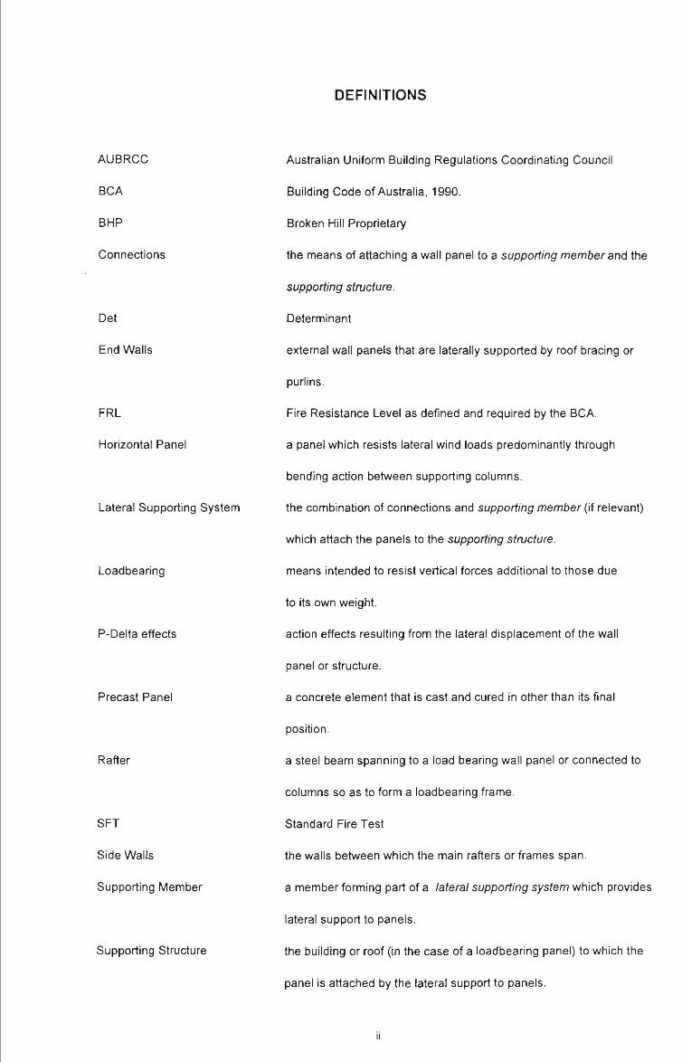
DEFINITIONS
AUBRCC
BCA
BHP
Connections
Det
End Walls
FRL
Horizontal Panel
Lateral Supporting System
Loadbearing
P-Delta effects
Precast Panel
Rafter
SFT
Side Walls
Supporting Member
Supporting Structure
Australian Uniform Building Regulations Coordinating Council
Building Code of Australia, 1990.
Broken Hill Proprietary
the means of attaching a wall panel to a supporting member and the
supporting structure.
Determinant
external wall panels that are laterally supported by roof bracing or
purlins.
Fire Resistance Level as defined and required by the BCA.
a panel which resists lateral wind loads predominantly through
bending action between supporting columns.
the combination of connections and supporting member (if relevant)
which attach the panels to the supporting structure.
means intended to resist vertical forces additional to those due
to its own weight.
action effects resulting from the lateral displacement of the wall
panel or structure.
a concrete element that is cast and cured in other than its final
position.
a steel beam spanning to a load bearing wall panel or connected to
columns so as to form a loadbearing frame.
Standard Fire Test
the walls between which the main rafters or frames span.
a member forming part of a lateral supporting system which provides
lateral support to panels.
the building or roof (in the case of a loadbearing panel) to which the
panel is attached by the lateral support to panels.

Tilt-up Panel a precast element normally cast on-site in a horizontal position
adjacent to its final location for lifting into position.
Vertical Panel a panel which resists lateral wind loads predominantly through
bending action over the height of the storey.

NOTATIONS
e strain; (mm/mm)
a stress; (kN/m2)
A total lateral displacement at top of wall - from analysis; (mm)
CT / fay proportional yield stress of steel; (kN/m2)
CT / fc proportional yield stress of concrete; (kN/m2)
5ir limiting value of relative lateral displacement; (mm)
f c compressive cylinder strength of concrete at 28 days (kN/m2)
fay(20 °C) design value for the yield point of steel for normal conditions of use; (kN/m2)
H' the height of the concrete panel considered for analysis; (m)
He the height of the column from the base of the wall to the uppermost connection between
panel and supporting member or lateral supporting system; (m)
Hf the vertical distance between connections on a horizontal panel; (m)
Hw the height of a wall for a single storey building; (m)
Mb the ultimate moment capacity at the base of a vertical panel; (kN-m per m)
Pw reinforcement ratio; (%)
tw the thickness of wall panel for a single storey building; (m)
Subscripts
c concrete
h horizontal
i internal
Ir limiting relative value
0 original
s steel
V vertical
w wall
IV

LIST OF FIGURES
Figure 2.1 BCA Concession for Steel Columns 2 - 3
Figure 2.2 Possible Deformed Shape of Single-Storey Industrial Building 2 - 4
Figure 2.3 A Single-Storey Non-Loadbearing Portal Frame Industrial Building 2 - 5
Figure 2.4 Typical Steel Clip Plate Bearing Connection 2 - 6
Figure 2.5 Schematic View of Various Vertical Panel Lateral Support Systems 2 - 6
Figure 2.6 Methods of Connection for Support in Fire 2 - 7
Figure 2.7 Forces and Moments Acting on the Portal Frame Members 2 -11
Figure 2.8 (a) Acceptable Inwards Collapse of Portal Frame 2 -14
Figure 2.8 (b) Unacceptable Outwards Collapse of Portal Frame 2 -14
Figure 2.9 Heating Situations Considered by O'Meagher et al. (1990) 2 -16
Figure 2.10 Deformation of a Cantilevered Wall 2 -17
Figure 2.11 Behaviour of Cantilevered Concrete Wall in Tilt-Up Construction 2 -19
Figure 2.12 External Eaves Tie Member 2 - 21
Figure 2.13 Anchorage of External Eaves Tie Member 2 - 22
Figure 3.1 Standard Fire Temperature Gradients at Varying Times of Exposure 3 - 3
Figure 3.2 The Two Cases Analysed for the Wall Model Study 3 - 4
Figure 3.3 The Two Cases as Modelled for the Analysis 3 - 4
Figure 3.4 Discretisation of the Cantilevered Concrete Wall 3 - 5
Figure 3.5 Stress-Strain Relationships for Reinforcing Steels at Elevated Temperatures 3 - 8
Figure 3.6 Stress-Strain Relationships for Siliceous Concrete at Elevated Temperatures 3 - 8
Figure 3.7 Equilibrium Equations for the Cantilevered Wall 3 - 9
Figure 3.8 Geometric Relationships Between Successive Points on a Curve 3-11
Figure 3.9 Locations of Initial Strain and Curvature Estimates at Segment j 3 -13
Figure 3.10 Analysis Flow Chart for the Solution of the Wall Model 3 -16
Figure 4.1 Temperature Distributions of Cases Considered in Modelling 4 - 3
Figure 4.2 Simplified Cases Analysed for Differential Heating 4 - 3
Figure 4.3 Cases Considered for Analysis of Restrained Wall Deformation 4 - 7
Figure 4.4 Idealised Connection Characteristics 4 - 9
Figure 4.5 Force at Connection where relative displacement is 5||. 4 -13
Figure 4.6 Wall Deformation Effects With and Without Supporting Structure 4 -14
Figure 4.7 Typical Horizontal Wall Panel Orientation and Deformation Characteristics 4 -15
Figure 4.8 Horizontal Wall Panel as Analysed in the Vertical Plane 4 -16
Figure 4.9 Horizontal Wall Panel as Analysed in the Horizontal Plane 4 -16
Figure 4.10 Interaction Between Deforming Horizontal Panel and Steel Frame 4 -18
Figure 4.11 Horizontal Panel Connection Characteristics 4 -18
Figure 4.12 Deformed Horizontal Wall Panel Orientation 4 - 21

Figure 5.1 Common Forms of Connections that Utilise Steel Clips 5 -1
Figure 5.2 System Capable of Minimising Prying Effects 5 - 2
Figure 5.3 Typical Clip Plate Bearing Connection Used in Experimental Testing 5 - 3
Figure 5.4 Details of Connection Samples Tested 5 - 6
Figure 5.5 Formwork and Reinforcement 5 - 7
Figure 5.6 Test Apparatus 5 - 8
Figure 5.7 Heating Up of Test Samples 5-12
Figure 5.8 Maintenance of Clip Plate Temperature Over Time 5 -12
Figure 5.9 Load Displacement Chart for Non-Welded Connections Tested at Ambient
Temperatures 5-14
Figure 5.10 Lacquered Clip Plate Under Strain 5-15
Figure 5.11 Failed NW-20 Clip Plates 5-15
Figure 5.12 Deformation of NW-20 Clip Plate 5-16
Figure 5.13 Bolt Elongation and Deformation of Test NW-20 5-16
Figure 5.14 W-20 Test Clip Plate Under Strain 5-17
Figure 5.15 Load Displacement Chart for Welded Connections Tested at Ambient
Temperatures 5-18
Figure 5.16 Premature Failure of W-20 Clip Plate 5-18
Figure 5.17 Premature Failure of Two-Way Support 5-19
Figure 5.18 Proper Failure of W-20 Clip Plate Test 5-20
Figure 5.19 Creep Effects for Non-Welded Connection Tested at 600°C 5 - 21
Figure 5.20 Creep Effects for Non-Welded Connection Tested at 800°C 5 - 23
Figure 5.21 Deformation of NW-600 Clip Plate Test 5 - 24
Figure 5.22 Final Plate Deformation of NW-600 Test 5 - 24
Figure 5.23 Plate and Bolt Deformation of W-600 Test 5 - 26
Figure 5.24 Creep Effects for Welded Connection Tested at 600°C 5 - 27
Figure 5.25 Creep Effects for Welded Connection Tested at 800°C 5 - 28
Figure 5.26 Failure of W-800 Test Showing Bolt Yielding 5 - 28
Figure 5.27 Bolt Deformation of W-800 Test 5 - 29
Figure A.I Case 1 - Mayne Nickless Storage Warehouse A - 2
Figure A.2 Case 1 - Mayne Nickless Storage Warehouse A - 3
Figure A.3 Case 1 - Mayne Nickless Storage Warehouse A - 3
Figure A.4 Case 1 - Mgyne Nickless Storage Warehouse A - 4
Figure A.5 Case 1 - Mayne Nickless Storage Warehouse A - 4
Figure A.6 Case 2 - Colortron Paint Storage Warehouse A - 6
Figure A.7 Case 2 - Colortron Paint Storage Warehouse A - 6
Figure A.8 Case 2 - Colortron Paint Storage Warehouse A - 7
Figure A.9 Case 3 - Pool Chemicals Warehouse A - 9
VI

Figure A.10 Case 3 - Pool Chemicals Warehouse A - 9
Figure A.11 Case 3 - Pool Chemicals Warehouse A -10
Figure A.I2 Case 4 - Toy Factory and Warehouse A -12
Figure A.13 Case 4 - Toy Factory and Warehouse A -12
Figure A.14 Case 5 - Carpet Call Warehouse A -14
Figure A.15 Case 5 - Carpet Call Warehouse A -14
Figure A.16 Case 5 - Carpet Call Warehouse A -15
Figure A.17 Case 5 - Carpet Call Warehouse A -15
Figure A.18 Case 5 - Carpet Call Warehouse A -16
Figure B.I Elastic Modulus versus Temperature - (Steel) B - 5
Figure B.2 Proportional Limit Stress versus Temperature - (Steel) B - 5
Figure B.3 Maximum Stress Level versus Temperature - (Steel) B - 6
Figure B.4 Compressive Strain versus Temperature - (Concrete) B - 6
Figure B.5 Compressive Strength versus Temperature - (Concrete) B - 7
Figure E.I Typical Compressometer Arrangement for Measurement of Longitudinal
Strain E - 2
Figure E.2 Stress-Strain Relationship for Cylinder MRL1304 E - 2
Figure E.3 Stress-Strain Relationships for Cylinder MRL 1307 E - 3
Figure E.4 Standard B-34 Tensile Coupon Test Specimen E - 3
Figure E.5 Stress-Strain Relationship for Coupon Test 1 E - 4
Figure E.6 Stress-Strain Relationship for Coupon Test 2 E - 4
Figure E.7 Stress-Strain Relationship for Coupon Test 3 E - 4
Figure F.I Un-Welded Clip Plate Connection F-1
Figure F.2 Development of Prying Force F - 3
Figure F.3 Welded Clip Plate Connection F - 3
VII
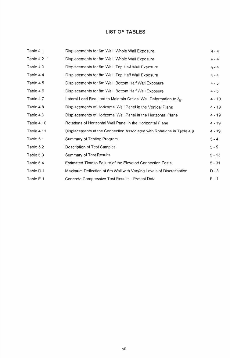
LIST OF TABLES
Table 4.1 Displacements for 6m Wall, Whole Wall Exposure 4 - 4
Table 4.2 ' Displacements for 8m Wall, Whole Wall Exposure 4 - 4
Table 4.3 Displacements for 6m Wall, Top Half Wall Exposure 4 - 4
Table 4.4 Displacements for 8m Wall, Top Half Wall Exposure 4 - 4
Table 4.5 Displacements for 6m Wall, Bottom Half Wall Exposure 4 - 5
Table 4.6 Displacements for 8m Wall, Bottom Half Wall Exposure 4 - 5
Table 4.7 Lateral Load Required to Maintain Critical Wall Deformation to 6|r 4 -10
Table 4.8 Displacements of Horizontal Wall Panel in the Vertical Plane 4 -19
Table 4.9 Displacements of Horizontal Wall Panel in the Horizontal Plane 4 -19
Table 4.10 Rotations of Horizontal Wall Panel in the Horizontal Plane 4 -19
Table 4.11 Displacements at the Connection Associated with Rotations in Table 4.9 4 -19
Table 5.1 Summary of Testing Program 5 - 4
Table 5.2 Description of Test Samples 5 -5
Table 5.3 Summary of Test Results 5-13
Table 5.4 Estimated Time to Failure of the Elevated Connection Tests 5 - 31
Table D.I Maximum Deflection of 6m Wall with Varying Levels of Discretisation D - 3
Table E.I Concrete Compressive Test Results - Pretest Data E-1
VIII

CHAPTER 1 INTRODUCTION
Single storey ^^rehouse buildings are a common form of construction. These buildings often
house large quantities of combustible materials, are rarely fitted with sprinklers, and often house
operations which are hazardous with respect to fire initiation.
It is not supnsing, therefore, that fires in such buildings are a frequent occurrence relative to the
frequency of fires in other commercial buildings. To date, there has been no evidence of death
resulting from fires in such buildings. This is probably attributable to the fact that most fires appear
to develop after hours when there are no or few occupants still present within the building.
Fires in these buildings are of concern to fire brigades as these fires tend to be very large.
Extinguishment of the fire is generally not possible and the role of the brigades is to assist with
preventing fire spread to the adjacent properties. This is usually done by playing water on the walls
of the adjacent buildings. Other important factors relevant to limiting fire spread, are the presence
of fire-resistant external walls and/or the spacing between the adjacent buildings.
The Building Code of Australia -BCA (1990), gives the fire-safety objectives of the regulations.
These are summarised as follows:
( i ) to provide an adequate level of safety for the occupants of the building and the fire
fighters;
( i i ) to provide an adequate level of protection for adjacent properties.
Traditionally f^0f^J^(pfm warehouse buildings have been constructed using steel frames and
masonry external walls. This was particularly the case where the external walls were required to be
fire-resistant when located closer than 3 m from the site boundary. Otherwise, the building was
clad with steel sheeting. Whilst in a large fire, the masonry walls eventually crumbled, they were
1 -1

considered to provide an adequate level of fire separation. Although the external walls within a
certain distance of the site boundary were required to have a fire-resistance level, the columns and
rafters were permitted to be unprotected and not required to achieve the level of fire-resistance
required for the walls. This situation is essentially the same today.
Changes in building fashion, technology, and construction economics have resulted in the external
walls of warehouse buildings being most commonly constructed using concrete panels. This is
sometimes the case even when a fire-resistant wall is not required.
The use of such concrete panels for the external walls of buildings has raised the question of
whether this form of construction can satisfy the above-mentioned objectives. To be specific, will
the panels become detached and fall outwards thus potentially endangering the life of fire fighters
outside the building and adjacent property? Are there special design considerations that should
apply to ensure that the above objectives can be achieved?
In this regard, the Building Code of Australia (1990), specifies the following:
C1.11 Performance of external walls in fire
( a) If a building having a rise in storeys of not more than 2 has concrete walls that could
collapse as complete panels (eg tilt-up and precast concrete), they must be designed
so that in the event of fire the likelihood of outwards collapse of the panels is
minimised.
(b) Compliance with Specification C1.11 satisfies (a).
Amendment 7, Building Code of Australia
^Cj/i^^p||6\j^ QKisi<^\s tM:^bk>e\LS^tie6 in "it>ore,,W9ii; and givejf a detailed description of current
warehouse construction. The behavioural characteristics of these buildings are described using a
number of case studies, and the literature on the subject is reviewed.
1 -2

As might be expected, various design approaches have been proposed to ensure adequate
behaviour in fire. The approaches are summarised and reviewed JfTtDfiapter 2.
The occurrence of a fire within a warehouse building will result in heating of the inside faces of the
external wall panels, as well as the unprotected steel frame. Heating of the inside of the panel will
cause it to deflect substantially - and it is possible that the deflection of the panel may be in a
different direction to that of the frames to which the walls are attached. T 6 study the deformation
la fe i^v icg f r^w^, a npfnericat-model was developed ,by ttfe author, Thisr^model is desoRto^dlh
/^h;apt^3.
y
In Chapter 4 the model is used to study the behaviour of isolated vertical and horizontal panels
under various heating regimes. The model is then used to evaluate the critical aspect of the design
philosophy developed by O'Meagher et al. (1991).
( Not only are the panels and the frame heating up during a fire but also the connections. It is
important, therefore, for the behaviour of connections under elevated temperature conditions to be
determined. This is the pur'pose of the experimental work presented Chapter 5.
r
' It is intended that the work presented in this thesis will provide background and data relevant to the
current debate on the behaviour of industrial buildings in fire.
1 -3

CHAPTER 2 BEHAVIOUR OF SINGLE-STOREY INDUSTRIAL
BUILDINGS IN FIRE - A REVIEW
2.1 introduction
The purpose of this chapter is to summarise and review the literature related to the behaviour and
design of single-storey industrial buildings in fire.
In recent years a number of researchers, particulariy in Australia, have attempted to understand
various behavioural aspects of these buildings in fire and various papers and reports have been
written that deal with these aspects as well as the principles for designing these structures.
The interest in the behaviour of these buildings has been largely generated from the debate about
whether it is necessary for the steel frames to be fire-protected in situations where the frames
provide lateral support to external wall panels, and from a concern about large concrete panels
falling outwards in the event of fire.
As noted in chapter 1, Clause C1.11 of Specification C1.1 of the BCA requires buildings with
concrete or reinforced masonry external walls to be designed, such that in the event of a fire, the
likelihood of outwards collapse of the wall is minimised.
According to Part A3 and Table C1.1 of the BCA, the single storey industrial buildings, which form
the subject of this thesis, are classified as Class 7, Type C construction. According to Table 5, a
building or compartment having an area of less than 3000 m2 must be surrounded by walls having a
fire-resistance level of 90 minutes if the walls are located closer than 3m from the fire-source
feature (normally the site boundary).
Two concessions are given in the BCA for these buildings.
2 -1

Spec. C1.1,2.5(a)
( i ) steel columns - except in a fire wall or common wall, a steel column need not have
an FRL in a building that contains only one storey.
In various situations, the use of unprotected steel roofing members is allowed.
Spec. 01.1, 3.5
( i i) Roof - A roof need not comply with Table 3 if its covering is non-combustible and the
building,
( a) has a sprinkler system installed throughout; or
( b ) has a rise in storeys of 3 or less; or
( c) is of Class 2 or 3; or
(d) has an effective height of not more than 25m and the ceiling
immediately below the roof has a resistance to the incipient spread
of fire to the roof space of not less than 60 minutes.
For a typical situation, (see Figure 2.1), the BCA requires the concrete wall panels to have an FRL
of 90/90/90. These numbers specify the performance requirements with respect to structural
adequacy, integrity and insulation. For a wall panel, integrity and insulation are essentially a
function of thickness and will easily be achieved provided the panel has sufficient thickness.
However it is important to note that typical wall panels will not achieve an FRL of 90 minutes with
respect to structural adequacy, unless they are laterally supported at the top I j ^ ^ elis^s^iomin
2 - 2
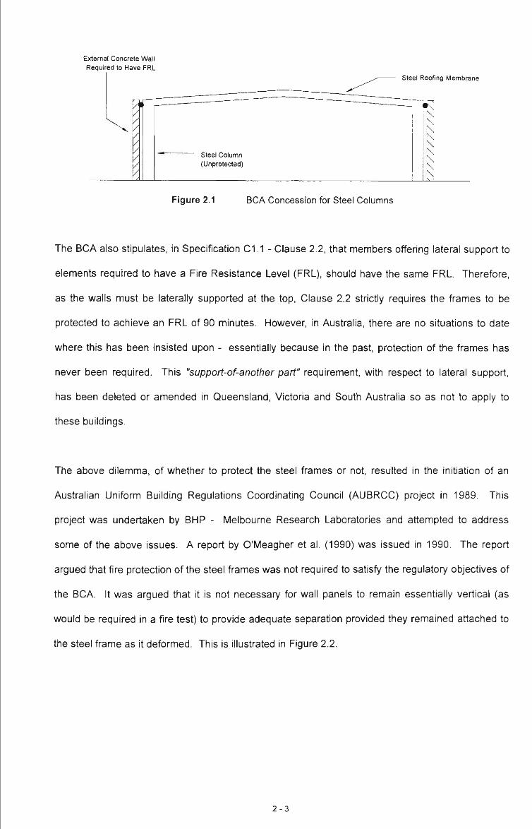
External Concrete Wall Required to Have FRL
Steel Roofing Membrane
Figure 2.1 BCA Concession for Steel Columns
The BCA also stipulates, in Specification C1.1 - Clause 2.2, that members offering lateral support to
elements required to have a Fire Resistance Level (FRL), should have the same FRL. Therefore,
as the walls must be laterally supported at the top. Clause 2.2 strictly requires the frames to be
protected to achieve an FRL of 90 minutes. However, in Australia, there are no situations to date
where this has been insisted upon - essentially because in the past, protection of the frames has
never been required. This "support-of-another part" requirement, with respect to lateral support,
has been deleted or amended in Queensland, Victoria and South Australia so as not to apply to
these buildings.
The above dilemma, of whether to protect the steel frames or not, resulted in the initiation of an
Australian Uniform Building Regulations Coordinating Council (AUBRCC) project in 1989. This
project was undertaken by BHP - Melbourne Research Laboratories and attempted to address
some of the above issues. A report by O'Meagher et al. (1990) was issued in 1990. The report
argued that fire protection of the steel frames was not required to satisfy the regulatory objectives of
the BCA. It was argued that it is not necessary for wall panels to remain essentially vertical (as
would be required in a fire test) to provide adequate separation provided they remained attached to
the steel frame as it deformed. This is illustrated in Figure 2.2.
2 - 3

External Concrete Wall acting as barrier
Deformed Steel Frame
and Roof Structure
Internal Fire Position
Figure 2.2 Possible Deformed Shape of Single-Storey Industrial Building
Effective compartmentation is also a regulatory requirement under the BCA* As to what constitutes
effective compartmentation, for single-storey buildings, the BCA states that if an external wall is
located up to 3m away from a fire source feature then no provision for an FRL is required. From
this it is considered that if the external wall provides at least this level of fire separation then
effective compartmentation has been satisfied.
In some cases where the external concrete wall panels deform inwards, to the extent of almost
becoming horizontal, the end result is a formation of a greater barrier to fire than a non-fire resistant
wall located 3m from the boundary. This boundary exists regardless of the time at which large
deformations or collapse occurs, so long as the wall remains effectively intact (O'Meagher et al.,
1990).
It was recognised that such gross deformation may result in gaps opening up between panels. This
strictly constitutes failure of the wall with respect to integrity^ - however the panels, even in this
state are considered to provide a substantial and sufficient barrier to radiation and flame. Even if
large gaps do form, then the concrete wall is still effective in acting as a fire barrier - more so than
that of a non-fire resistant wall located 3m from the boundary. See also Part C3 Clause C3.1(a)(ii).
The importance of adequate connections between the panels and the supporting frame was also
noted by O'Meagher et al. (1990).
Defined in AS 1530.4 as the development of cracks and fissures which allow the passage of flame and hot gases to pass.
2 - 4
The conclusions of the above report were accepted by AUBRCC and changes to Clause C2.2 are
currently being considered to bring regulation uniformity across the States.
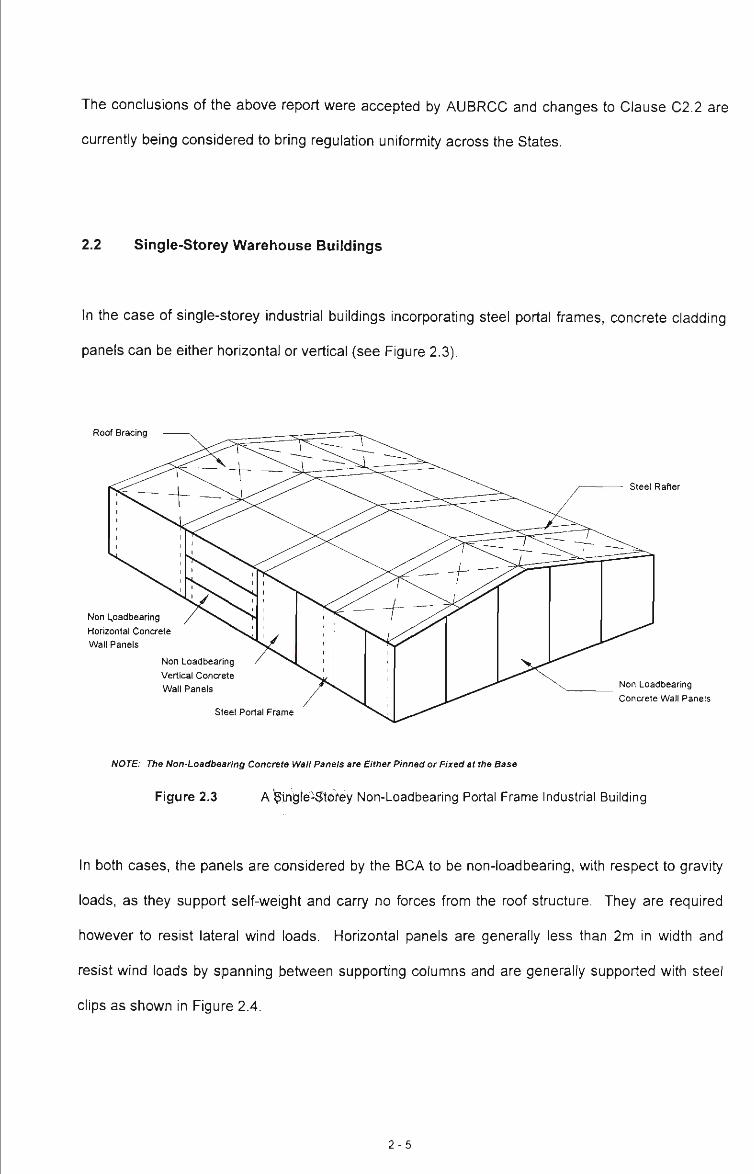
2.2 Single-Storey Warehouse Buildings
In the case of single-storey industrial buildings incorporating steel portal frames, concrete cladding
panels can be either horizontal or vertical (see Figure 2.3).
Roof Bracing
Non L,oadbearing
Horizontal Concrete
Wall Panels
Non Loadbearing
Vertical Concrete
Wall Panels
steel Rafter
Non Loadbearing
Concrete Wall Panels
Steel Portal Frame
NOTE: The Non-Loadbearing Concrete Wall Panels are Either Pinned or Fixed at the Base
Figure 2.3 A ingfe-Storey Non-Loadbearing Portal Frame Industrial Building
In both cases, the panels are considered by the BCA to be non-loadbearing, with respect to gravity
loads, as they support self-weight and carry no forces from the roof structure. They are required
however to resist lateral wind loads. Horizontal panels are generally less than 2m in width and
resist wind loads by spanning between supporting columns and are generally supported with steel
clips as shown in Figure 2.4.
2 - 5
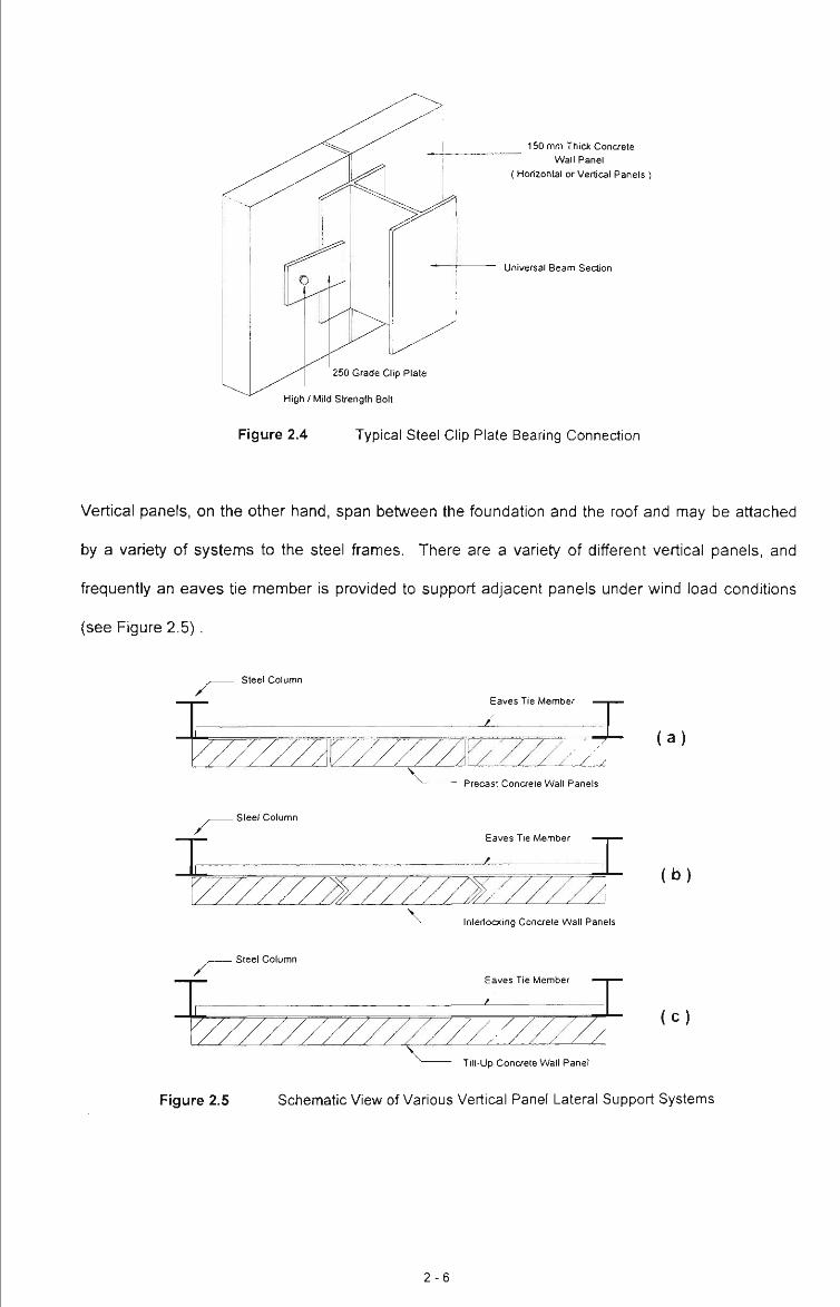
150 mm Thick Concrete Wall Panel
( Horizontal or Vertical Panels )
Universal Beam Section
250 Grade Clip Plate
High / Mild Strength Bolt
Figure 2.4 Typical Steel Clip Plate Bearing Connection
Vertical panels, on the other hand, span between the foundation and the roof and may be attached
by a variety of systems to the steel frames. There are a variety of different vertical panels, and
frequently an eaves tie member is provided to support adjacent panels under wind load conditions
(see Figure 2.5).
steel Column
- Steel Column
- Steel Column
Eaves Tie Member -I / / /
Precast Concrete Wall Panels
Eaves Tie Member z V Interlocking Concrete Wall Panels
Eaves Tie Member
-^ T V Tilt-Up Concrete Wall Panel
( a )
( b )
( c )
Figure 2.5 Schematic View of Various Vertical Panel Lateral Support Systems
2 - 6
Precast Concrete Panel
I Clip Plate Detail Option 1 y
^ ^ ^ ^
High Strength Bolt/Ferrule Connection
UB Section
( a )
Clip Plate Detail Option 2
- &
UB Section
Clip Plate Detail Option 3
Precast Conaete Panel
( b )
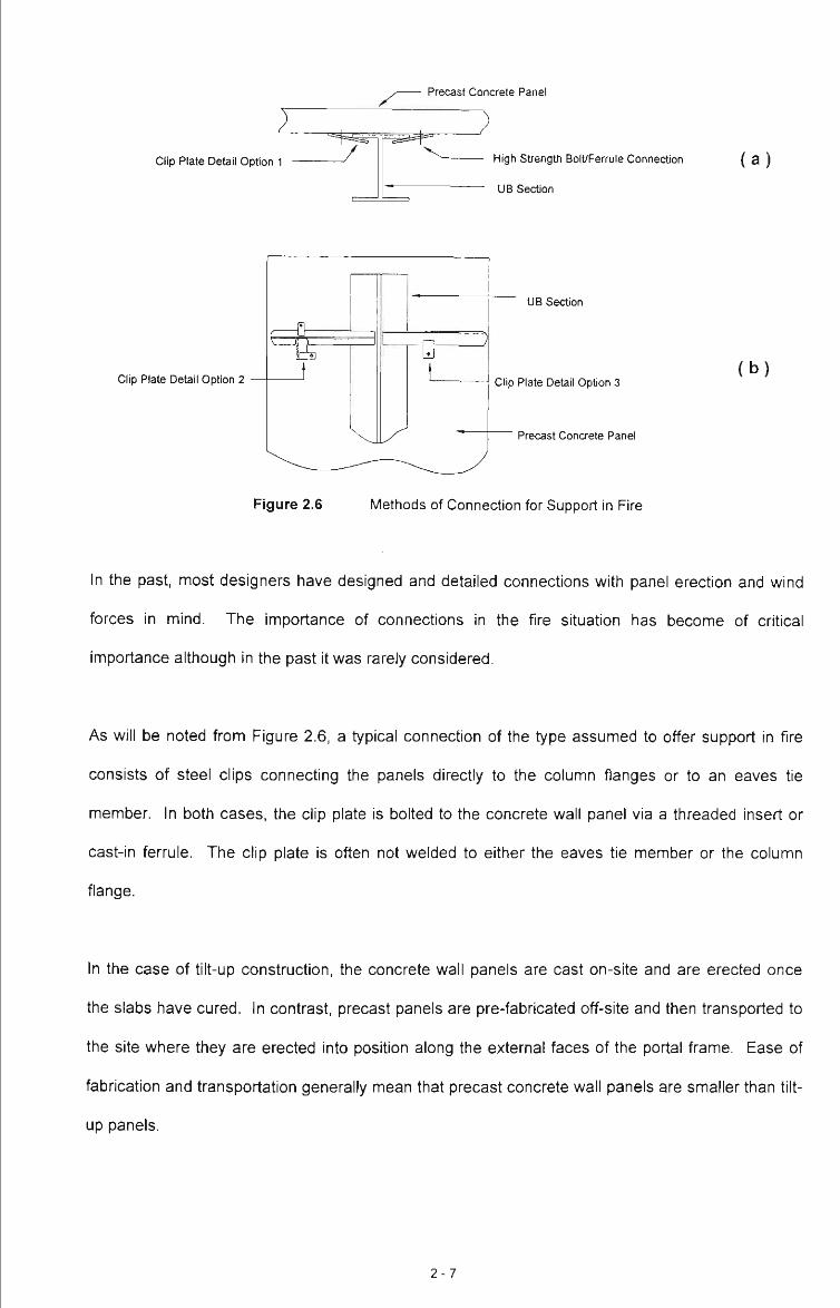
Figure 2.6 Methods of Connection for Support in Fire
In the past, most designers have designed and detailed connections with panel erection and wind
forces in mind. The importance of connections in the fire situation has become of critical
importance although in the past it was rarely considered.
As will be noted from Figure 2.6, a typical connection of the type assumed to offer support in fire
consists of steel clips connecting the panels directly to the column flanges or to an eaves tie
member. In both cases, the clip plate is bolted to the concrete wall panel via a threaded insert or
cast-in ferrule. The clip plate is often not welded to either the eaves tie member or the column
flange.
In the case of tilt-up construction, the concrete wall panels are cast on-site and are erected once
the slabs have cured. In contrast, precast panels are pre-fabricated off-site and then transported to
the site where they are erected into position along the external faces of the portal frame. Ease of
fabrication and transportation generally mean that precast concrete wall panels are smaller than tilt-
up panels.
2 - 7

Once the floor slab is poured, the steel portal frame is able to be positioned and fixed into place.
The steel frame is generally rectangular in shape with single spanning frames spaced at regular
distances along the length of the building as shown in Figure 2.3. Bracing is provided in the roof to
facilitate resistance to end wall wind loading and to provide overall stability.
In practice, the roof sheeting in association with the puriins, can provide substantial in-plane bracing
at the roof level (Bryan, 1972). During the early stages of fire development it is likely that the roof
will continue to provide significant restraint - especially away from the fire (O'Meagher et al., 1990).
Once the portal frame is erected the concrete panels are then positioned in place by connecting the
base of the panel to the footing and the panels to the steel portal frame.
2.3 Building Behaviour in Fire
In the event of fire in a single-storey industrial building, there are a number of possible scenarios
depending on the severity of the fire (O'Meagher et al., 1990 and Gnanakrishnan, 1990). The steel
frames may undergo severe deformation; panels may deform significantly and become detached
from the supporting frame; alternatively, relatively little damage may occur.
In this chapter the influences of fire on a single frame, on an isolated wall panel, and on the overall
building are considered. The role of the connection between concrete panels and frame is also
discussed.
2.3.1 The Developing Fire Concept
Real fires are highly variable and difficult to quantify. Factors that most affect the fire characteristics
are as follows; (Malhotra, 1982):
2 - 8

• the quantity and orientation of combustibles stored within the building,
• the nature and geometry of the combustibles, and
• the degree of ventilation.
In a real fire situation, it is reasonable to assume that the fire develops slowly from the time of
initiation, with various parts of the roof and walls being heated at different rates. As the fire
escalates in size, so too does its' intensity. It Is likely that the growing fire will heat the adjacent
members differentially leading to variations in steel and air temperatures throughout the building.
This scenario has been described in terms of a "developing fire concept" by O'Meagher et al.
(1990).
The above authors consider that it is unlikely that a steel frame will be at a uniform high temperature
but that parts of a fire-affected frame will be at different temperatures.
Other gradients in temperature are likely. For example, it is likely that while the fire is small, the
highest air temperatures will be closest to the fire. As the fire further develops, the temperature
close to the roof will increase. However, substantial venting of the flames through the roof will
probably result in a reduction of air temperature near the roof members.
2.3.2 Frame Behaviour
The behaviour of a steel frame in fire is now considered.
Much can be learnt from studying the geometry of buildings after the occurrence of fire, and post-
fire observations associated with a number of large fires in steel-framed industrial buildings, jffp
^p€[rTO4 ill4pp'en^b^ A: Some of the observations have been reported in the literature whilst others
are the result of investigatory work undertaken as part of this research project.
2 - 9
Observations of post-fire industrial buildings show the steel frame structure having deformed and
distorted away from the external concrete wall panels. Due to the heat transfer effects of the
Internal fire, the steel roof members have a tendency to feel the effects of the fire prior to other
structural components within the building and tend to warp and collapse under their own self-weight.
The frame then collapses inwards as the rafters sag and collapse forcing the steel columns to follow
this deformation due to the rigid connection that exists between the column and the rafter at the
haunch.
A number of publications have addressed the behaviour of the frames in fire and these are now
considered.
Constrado - [1980]
In 1980, Constrado published a document entitled "The Behaviour of Steel Portal Frames in
'/ Boundary Conditions". At this time the building regulatory authorities in the United Kingdom were
suggesting that perhaps it was necessary to fire protect the entire portal frame assembly, as
opposed to just the columns. This document was prepared in response to this issue.
In the United Kingdom, it is very rare for portal frame buildings to have concrete panels as wall
cladding. Due to the climate, specific thermal insulation requirements must be achieved and walls
are either of insulated steel or masonry construction. Therefore this publication does not consider
the interaction between concrete wall panels and frames.
Regulations in the United Kingdom, require only the column to be protected. This has always been
the case.
The above publication considered the behaviour of frames in fire from a "common sense"
engineering approach.
2-10

According to this publication, as the fire escalates in growth and intensity, the members within the
roofing membrane are affected the most. As the temperatures increase within this upper region of
the building, the strength and stiffness of the structural steelwork are reduced. The steel rafters
tend to heat up and expand which Initially causes an outward movement of the eaves. This results
in the formation of plastic hinges close to the eaves as the bending moments at the eaves increase.
The combination of Increased bending moments and axial force in the rafter (see Figure 2.7) was
recognised as leading to fiexural - torsional buckling such that the rafter may end up with its web in
a horizontal position.
induced axial compression
F - ^ bending moment induced by rafter
1 expansion
Figure 2.7 Forces and Moments Acting on the Portal Frame Members - Free Body Diagram
As the rafter undergoes gross deformation downwards, the columns will be pulled inwards.
The above publication suggests that adequate frame behaviour will be achieved if the base
connections of the frame have sufficient moment capacity. The required capacity was determined
as follows:
( i ) observation of some actual fires in warehouses suggested that typical deformations were
such that the columns rotated inwards by «1°.
2-11

( i i ) assuming this displaced shape, and the position of the point of contraflexure within the
rafter, the bending moment at the base required for equilibrium was determined.
( i i i ) the base connection, which is protected because the column is protected, must be
designed to achieve this capacity. In practice this is relatively easy to achieve. "Pinned
connections" are not recommended.
The above approach is based on the assumption of a symmetrical fire and of a certain firame
geometry. In Australia, at least, column rotations - even when columns have been protected - have
often been found to exceed the assumed 1°. Column rotations of more than 15° have been
obtained (see Appendix A). The final geometry of the frame is dependent on the severity of the fire.
The Constrado publication also recognises that frames that have collapsed inwards (ie. the frames
nearest the point of fire origin) will provide some restraint to the remainder of the steel structure,
thus minimising the chances of an outwards overall collapse.
Gnanakrishnan - [1993]
The report prepared by Gnanakrishnan, (1993), entitled "Likely Fire Performance of One and Two
Storey Buildings witii Precast Concrete or Tilt-up Panels or Precast Concrete Cladding", does not
consider frame behaviour in a quantitative manner but makes a number of general post-fire
observations.
Gnanakrishnan analysed the behaviour of various structural components subject to fire but did not
attempt to analyse the entire building structure subject to these conditions.
Regarding the behaviour of the steel frame in fire, Gnanakrishnan gives a brief description of the
stages of collapse of a steel frame based on post-fire observations.
2-12

The development of a typical industrial building fire was considered qualitatively with respect to the
likely behaviour of the entire building subject to various fire exposures. The fire scenarios
considered were:
( i ) internal fire adjacent to an external wall
( i i ) internal fire adjacent to an internal wall
(I i i ) internal fire at the corner of a building
(iv ) internal fire, (not reaching the roof), on the ground floor
( V ) internal fire spread throughout the building
(v i ) external fire near a wall
Gnanakrishnan concludes that intensity, spread and duration of the fire in a building are dependent
on the initial fire source, availability of fuel, building size, building openings and ventilation. The
problem of analysing the fire behaviour of the entire building structure was recognised as being too
difficult due to the large number of contributing factors.
Gnanakrishnan observes that modern industrial buildings of this type often contain a vast variety of
stored goods; varying in both quantities and volatility and that it is because of this that high
temperatures can occur within these buildings. The combination of severe fires and unprotected
steel is considered to give rise to substantial deformations of the frames.
Gnanakrishnan describes the behaviour of the steel column / concrete wall panel interface as
follows:
"Through the effects of the increased fire load, present within the building, the steel column has a
tendency to expand and bend slightly; ie. bow inwards. This is due to partial shielding of the
column flange abutting the wall panel. The concrete's low conductivity causes the panels to bow
outwards and exert considerable force on the connections which would have already suffered a
2-13
loss in strength due to increased fire exposure. These additional forces would cause the
connections to fail and would result in the wall cladding collapsing."
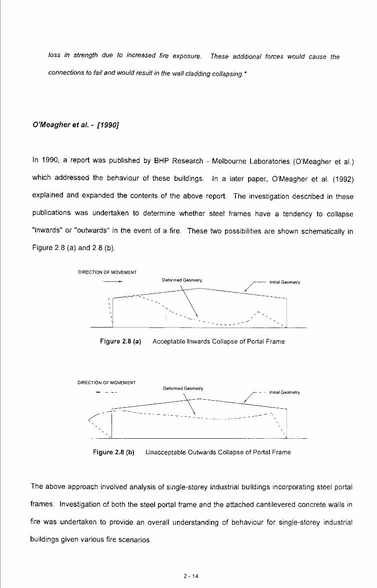
O'Meagher et al. - [1990]
In 1990, a report was published by BHP Research - Melbourne Laboratories (O'Meagher et al.)
which addressed the behaviour of these buildings. In a later paper, O'Meagher et al. (1992)
explained and expanded the contents of the above report. The investigation described in these
publications was undertaken to determine whether steel frames have a tendency to collapse
"inwards" or "outwards" in the event of a fire. These two possibilities are shown schematically in
Figure 2.8 (a) and 2.8 (b).
DIRECTION OF MOVEMENT
Deformed Geometry Initial Geometry
Figure 2.8 (a) Acceptable Inwards Collapse of Portal Frame
DIRECTION OF MOVEMENT Deformed Geometry
Initial Geometry
Figure 2.8 (b) Unacceptable Outwards Collapse of Portal Frame
The above approach involved analysis of single-storey industrial buildings incorporating steel portal
frames. Investigation of both the steel portal frame and the attached cantilevered concrete walls in
fire was undertaken to provide an overall understanding of behaviour for single-storey industrial
buildings given various fire scenarios.
2-14

Some of the key factors that were taken into account were:
( i ) the effect of elevated temperature on steel properties,
( i i ) the effect of differential heating,
(iii) the effect of second-order displacements on frame behaviour,
( iv) the presence of a lateral in-plane restraint to the frame from the roof,
(V ) the restraint provided by the column base connections, and
( vi) loads due to the attached extemal concrete walls and the portal roof structure.
The frame geometries adopted for the analysis were 15 m and 20 m span portals, each having a
height of 6.5m. Two different steel section sizes were used for each of the above geometries.
Various heating scenarios were considered by imposing a number of distributions of temperature
around the frame as shown in Figure 2.9.
2-15

Cool Zone
3T/4
Situation A
Cool Zone -
Situation C
3T/4
^
Cool Zone
Situation B
Situation D
Cool Zone ^ / l
Situation E
Cool Zone
h
Cool Zone .—/ I Cool Zone
Situation F
Temperature. T
Cool Zone
Situation G
Figure 2.9 Heating Situations Considered by O'Meagher et al. (1990)
The frames were analysed using the finite element program ABAQUS with the frame temperature
being increased until very large displacements occurred.
As a result of the above analyses, it was found that plastic hinges (regions of extensive plasticity)
were formed at or near one end of the rafter and within the rafter close to the end of the heated
region. These hinges are caused by the yielding of the rafter as the yield stress of the steel falls
with an increase in temperature and as the bending moments due to thermal effects increase.
The analyses results showed that the desired frame deformation (see Figure 2.8 (a)) will, in
practice, be achieved. This was found to be true irrespective of whether the fi-ame supports
concrete wall panels, or whether the columns are protected. For frames with "pinned" base
2-16
connections, desirable frame deformations ("inwards" deformations) were obtained for all
unsymmetrical frame temperature distributions. In practice, unsymmetrical ft-ame temperature
distributions will always occur. However, even for ft-ames with unifonn temperature distribution, the
desirable deformations occurred provided a small degree of moment resistance was present at the
base connections. The level of resistance required will be easily achieved by practical base details.
That desirable frame geometries are obtained in real fires is supported by the findings presented in
Appendix A.
It was also recognised that as the fire develops within a building, and as the frames progressively
deform, the frames will act as "anchors" to the rest of the building.
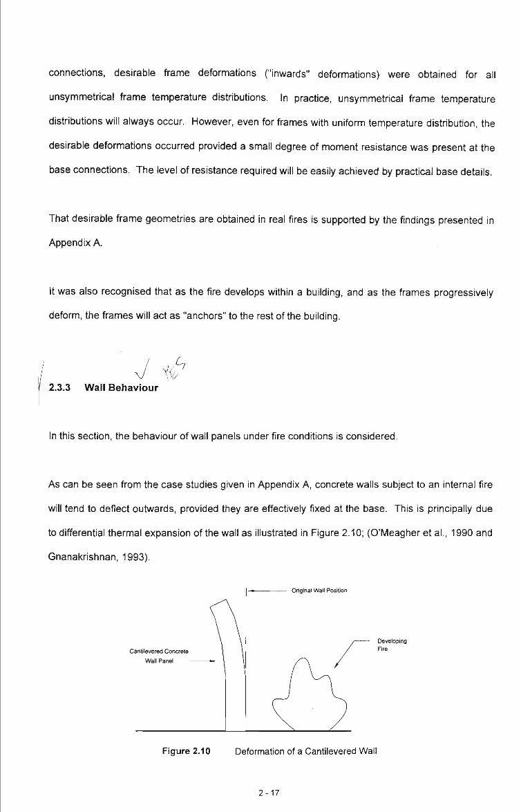
^ ^ 2.3.3 Wall Behaviour
In this section, the behaviour of wall panels under fire conditions is considered.
As can be seen from the case studies given in Appendix A, concrete walls subject to an internal fire
will tend to deflect outwards, provided they are effectively fixed at the base. This is principally due
to differential thermal expansion of the wall as illustrated in Figure 2.10; (O'Meagher et al., 1990 and
Gnanakrishnan, 1993).
Original Wall Position
Cantilevered Concrete
Wall Panel
Developing Fire
Figure 2.10 Deformation of a Cantilevered Wall
2-17
If the vertical wall panel is dowelled at the bottom, and supported laterally at the top, it will behave
as if it is a cantilever due to prying against the column flange. Tffi|t^ aspect of behaviour is
^^fe^Lisseciat^^ome^lerrgth in Chapter<
Constrado (1980), does not consider the behaviour of any attached concrete walls, as in the United
Kingdom, walls are almost entirely insulated steel or masonry construction.
O'Meagher et al. (1991), have looked extensively at the behaviour of reinforced and prestressed
concrete wall panels under fire conditions. ^;eValu^tIoh of isolated wall behaviour is presented in
Cf>^pter S' usrqg a variation of the methbd used by O'Meagher and Bennetts, (1991). Both vertical
and horizontal panels are considered.
Gnanakrishnan (1993), considers that concrete wall panels may suddenly fall either inwards or
outwards without any visible sign of warning. This scenario is both undesirable and unacceptable
and, as noted previously, may result in damage to adjacent buildings or persons. However, it is
difficult to see how inwards collapse - particulariy if the panel movement is controlled by the
deforming frame - can have an adverse infiuence on life safety. In order to obtain such
deformations, the fire must be well developed within the building - well beyond the stage that
firemen would be able to fight the fire from within the building.
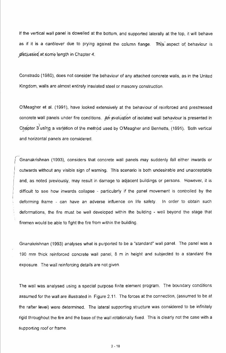
Gnanakrishnan (1993) analyses what is purported to be a "standard" wall panel. The panel was a
190 mm thick reinforced concrete wall panel, 8 m in height and subjected to a standard fire
exposure. The wall reinforcing details are not given.
The wall was analysed using a special purpose finite element program. The boundary conditions
assumed for the wall are illustrated in Figure 2.11. The forces at the connection, (assumed to be at
the rafter level) were determined. The lateral supporting structure was considered to be infinitely
rigid throughout the fire and the base of the wall rotationally fixed. This is cleariy not the case with a
supporting roof or frame.
2-18

No account was taken of the interaction of the wall curvature with columns - there is a basic
incompatibility between the straight column flange and the wall curvature.
fixed support
supporting steel roof
developing fire
cantilevered concrete wall panel Wall as analysed
schematically
footing
Figure 2.11 Behaviour of Cantilevered Concrete Wall in Tilt-Up Construction; (Gnanakrishnan, 1993)
It is Gnanakrishnan's view that canfilevering the base of the concrete wall is beneficial and will
minimise the likelihood of outward collapse. He suggests that in cases where the concrete wall
panel is pinned at its base, the connection at the top of the wall must remain intact in order for the
wall panel to stay attached to the supporting structure.
2.3.4 Support of Walls
This matter has been considered by both O'Meagher et al. (1990) and Gnanakrishnan (1993).
O'Meagher et al., (1990), consider that integrity of the connection between panels and frame is
essential in minimising the likelihood of outwards collapse.
If vertical wall panels are effectively fixed at the base, they will deflect outwards away from the fire,
and as noted previously, the steel frames may undergo substantial deformation with one column
moving inwards - ie. in the opposite direction to the wall. It is clear, therefore, that the connections
must also possess sufficient displacement capacity to allow for such relative displacement. Recent
2-19
work by O'Meagher et al. (1994), has attempted to establish appropriate design criteria for such
connections.
The importance of both strength and ductility to a connections' behavioural aspects is reinforced by
some real fire s i tua t ions^^ i^^^^ j f f ^pendix^A. These issues of strength and ductility are
/corisi/iered in greater detail in Chapter^ 4 and 5.
I Gnanakrishnan (1993), recognises the importance of connection strength but makes no reference
to ductility requirements - "failure of the connections is the most important contributory factor to the
! j instability of the wall panels".
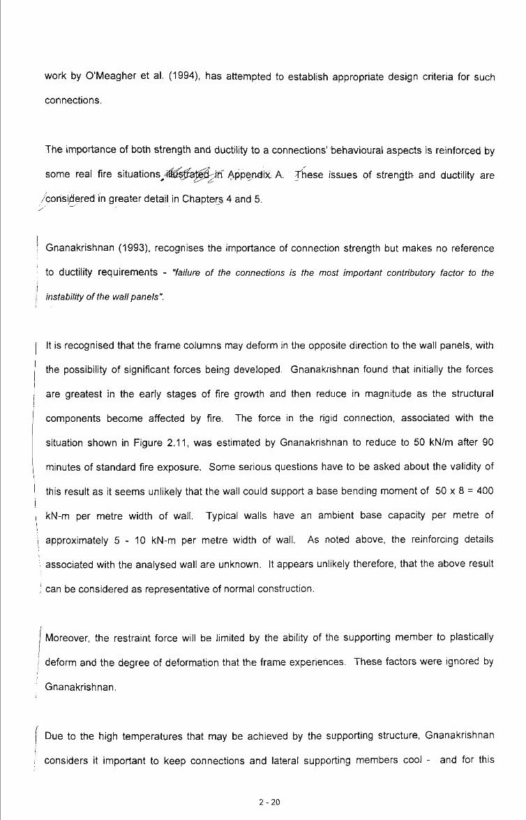
It is recognised that the frame columns may deform in the opposite direction to the wall panels, with
the possibility of significant forces being developed. Gnanakrishnan found that initially the forces
are greatest in the early stages of fire growth and then reduce in magnitude as the structural
components become affected by fire. The force in the rigid connecfion, associated with the
situation shown in Figure 2.11, was esfimated by Gnanakrishnan to reduce to 50 kN/m after 90
minutes of standard fire exposure. Some serious questions have to be asked about the validity of
this result as it seems unlikely that the wall could support a base bending moment of 50 x 8 = 400
kN-m per metre width of wall. Typical walls have an ambient base capacity per metre of
approximately 5 - 1 0 kN-m per metre width of wall. As noted above, the reinforcing details
associated with the analysed wall are unknown. It appears unlikely therefore, that the above result
can be considered as representative of normal construction.
Moreover, the restraint force will be limited by the ability of the supporting member to plastically
deform and the degree of deformation that the frame experiences. These factors were ignored by
Gnanakrishnan.
Due to the high temperatures that may be achieved by the supporting structure, Gnanakrishnan
considers it important to keep connections and lateral supporting members cool - and for this
2-20

reason he recommends that connections and supporting members are provided along the outside
face of the wall. It is recommended that a lightweight eaves member can be run around the outside
of the building as illustrated in Figure 2.12. This member is to be designed to resist the lateral
forces applied by the outwardly bowing concrete wall panels.
External Eaves Tie Member
Concrete Wall Panels
Figure 2.12 External Eaves Tie Member
However, the authoiSconsider<|'this recommendation to have limited appeal due to the additional
cost, architectural appearance, and concerns about corrosion. Furthermore, this system will only
work provided the eaves member is capable of acting as a catenary member - a light channel may
not have sufficient bending strength. The member should be connected to each frame and at the
end of the building would need to be properiy anchored. These aspects are not mentioned by
Gnanakrishnan who appears to assume that the eaves member can span from one end of the
building to the other. This could only be achieved if the member acts as a cable and would require
effective anchorage at the ends of the building (see Figure 2.13). It is extremely difficult to see how
the eaves member or anchorages could resist a lateral force of 50 kN/m.
2-21

Plan of Building
Forces Applied from Extemal Wall Panels
Anchorage Required Eaves Tie Member
Figure 2.13 Anchorage of External Eaves Tie Member
Alternatively, O'Meagher et al. (1990) consider that the use of non-fire rated connections is not a
major problem with regards to providing adequate structural behaviour provided they have sufficient
strength and ductility.
Gnanakrishnan also considers the use of nylon bolts to connect the wall panels to the supporting
structure. If the panels are cantilevered, the use of such bolts, it is argued, will allow the separation
of structure and panels such that the panels will continue to resist the fire effects through cantilever
action. The unprotected steel frame will therefore, in theory, be allowed to collapse without
affecting the structural adequacy of the external walls.
In the opinion of the autho]]J>this is a dubious approach - especially for practical walls with minimum
quantities of reinforcement./As will be shown in Chapter 4. pese walls do not exhibit a high level of
fire-resistance as isolated cantilevers, and given a fire of sufficient magnitude, may well collapse
outwards.
2-22

2.4 Summary of Design Philosophies y
The different design philosophies are now summarised as follows:
According to the Constrado publication, (1980):
1. portal frame rafters do not require fire protection;
2. the foundations, column and column base should be designed to resist the overturning moment
at the base of the column - assuming a nominated frame geometry;
3. protection of the column has always been required in the United Kingdom. The validity of this
requirement was not addressed.
Alternatively, Gnanakrishnan (1993) gives the following design recommendations that:
1. adequate base capacity for the wall must be provided;
2. the provision of a continuous eaves tie should be provided on the outside of the building - no
details are given regarding connection of this external tie member to the supporting columns;
3. the size of the above mentioned eaves tie should be designed to resist a force of
approximately 50 kN/m per metre width of wall. As noted previously, it is difficult to see how
forces of this magnitude can be achieved or resisted.
On the other hand, O'Meagher et al. (1994) have suggested the following philosophy:
1. the steel frames, in the event of a fire, will deform in a safisfactory manner;
2. provided the panels remain attached to the portal frame they will not collapse outwards;
3. the connections between the steel supporting structure an the concrete panels must be
designed to have sufficient ductility and adequate strength at elevated temperature;
4. adequate allowance for relative movement between the concrete wall panel and the structural
steel portal frame must be made to allow for the difference in wall and frame deformations.
2-23

CHAPTER 3 MODELLING OF CONCRETE WALLS IN FIRE
3.1 Introduction
In this chapter a mathematical model is developed to study the structural behaviour of reinforced
concrete walls when subject to elevated temperatures due to fire on the internal face.
As highlighted in the previous chapters, the interaction between the supported external walls and
the supporting steel structure is of critical importance in determining whether the separation of wall
and structure will occur, and it is the deformation and resistance of the external walls that, to a large
extent, determines the forces developed at the connections between the frame and the wall. The
analysis model described in this chapter is used in Chapter 4 to study the behaviour of some typical
walls and to provide some insights into the design requirements for connections.
In developing the mathematical model described in this chapter, a number of convergence
problems were encountered. These problems are discussed.
3.2 Elevated Temperature Analysis
To model the behaviour of concrete walls subject to elevated temperatures, it is necessary to
determine the temperature distribution across the wall at any given time. This is achieved through
analysing the heat fiow characteristics through the concrete wall for a given imposed heafing
situation.
The model developed in this chapter assumes that the wall is subjected to heating on one side only.
This is appropriate for the situation being considered as the fire is either inside or located external to
3 - 1

the building. The former situation will generally subject the wall and the structure to the most
intense heat and Is therefore exclusively considered in this study.
The calculation of temperatures throughout the wall was undertaken using the finite element
program TASEF-2 (WickstrOm, 1983). The program is a transient two-dimensional heat flow
analysis and enables a number of materials to be considered, including concrete and steel.
Conservative thermal properties (i.e. properties likely to give higher than normal temperatures for
thermal conductivity, heat capacity and moisture content) are adopted for concrete. Any heating
situation can be imposed on one face of the wall by specifying a time-temperature relationship, and
appropriate values of radiative and convective heat transfer coefficients. Specific coefficients are
recommended for simulating the standard fire test heating environment (WickstrOm, 1983).
In practice, as noted in the previous chapter, real fires are highly variable. For the purpose of the
analysis conducted in Chapter 4, the fire is assumed to correspond to an ISO standard fire of some
duration. The use of the ISO standard fire exposure relationship is adopted not only for simplicity
but also because it will enable a good estimate of the relative performance of the concrete walls
subject to various fire scenarios and because it is the basis for current regulatory requirements for
walls. The vast majority of fire engineering designs are based at present on the standard fire
exposure (Twilt, 1988).
In the standard fire test it is required that the temperature-time relationship follows the following
equation.
Tf = To + 345 logio (480t +1) Eq. ( 3.1 )
where:
Tf Fire Temperature (°C)
To Ambient Temperature (°C)
t Duration of Fire Exposure (min)
3 - 2

To calculate the temperatures through the wall using TASEF-2, the wall must be discretised across
its thickness into a number of elements. The appropriate fire-time temperature curve and heat
transfer coefficients, and the material thermal properties must also be specified. Comparison of
temperatures predicted using TASEF-2 with measured temperatures obtained during standard fire
tests (The Institution of Structural Engineers, 1978) indicate good agreement, with the predicted
temperatures being generally greater nearer to the heated surface; see Figure 3.1 .
The temperatures through a 150 mm wall, when subject to 30, 60 and 90 minutes of standard fire
test exposure on one side of the wall are shown in Figure 3.1.
u D> 0) Q
3 4-1 s o o. E
K -
5
1000
900
800
700
600
^ 500
400
300
200
100
A
^ ' . ^ J
\ \ X* ^ \ ^
>^^
^ >
' '' "-i l Z ^
J:-:
1^ o r - CO
LO o CO
If) 1^ o in
O o CM
in CO o
in Distance From Heated Face, (mm)
TASEF 30 min
TASEF 60 min
TASEF 90 min
- • Experimental 30 min
< Experimental 60 min
^ Experimental 90 min
Figure 3.1 Standard Fire Temperature Gradients at Varying Times of Exposure for 150 mm Thick Concrete Wall - [TASEF-2 versus Experimental Results]
At the interface, between the wall and the fire, the temperature is assumed to be that associated
with the fire. The temperatures away from this junction fall rapidly. The temperature gradient varies
with time of fire exposure, being greatest for 30 minutes. This suggests that most of the thermally
induced wall deformations will occur during the eariier stages of fire exposure.
3-3

3.3 Modelling of the Wall
For the purpose of developing a mathematical model, the cases shown in Figure 3.2 have been
considered. The situation shown in (a) represents a vertical wall panel which is effectively
rotationally restrained at the base and subject to a horizontal load at the top of the wall in addition to
its own self weight acting in a vertical direction (see also Figure 3.3). As will be demonstrated in
Chapter 4, this situation always occurs where a vertical panel is connected to a steel frame such
that it is directly adjacent to a column. The situation shown in (b) represents a horizontal wall panel
which is partially rotationally restrained at each end of the panel at the column support via a clip
connection. This often occurs where a horizontal panel is connected to a steel frame.
Deformed Panel -
r \ \ \
" x 1 \ \ \
1 \ \ \
1 \ \
]
1
Portal Frame
Fire
Portal Frame
VERTICAL PANEL CASE HORIZONTAL PANEL CASE
(a) (b)
Figure 3.2 The Two Cases Analysed for the Wall Model Study
The above cases were modelled as shown in Figure 3.3 .
Lateral Load, P
Vertical Panel Rotational Restraint
Fire
Fire
Horizontal Panel
%
HORIZONTAL PANEL CASE
(PLAN VIEW)
(b) VERTICAL PANEL CASE
(a)
Figure 3.3 The Two Cases as Modelled for the Analysis
3 - 4

The method of analysis presented in this chapter assumes that the wall can be analysed as a one
way member with curvature in only one direction. This is likely to lead to an over-estimate of
displacements. Nevertheless, it is a reasonable and conservative assumption.
3.3.1 Discretisation of Wall Model
For the purpose of analysis, the wall is discretised across its thickness and length as shown in
Figure 3.4.
The analysis program allows for different numbers of elements and segments.
Exposed to Standard Fire Time-Temperature Curve
Unit Segments Length
Figure 3.4 Discretisation of the Cantilevered Concrete Wall
The effect of increasing the number of segments up the wall has been investigated and the results
of this analysis are given in Appendix D.
3 - 5
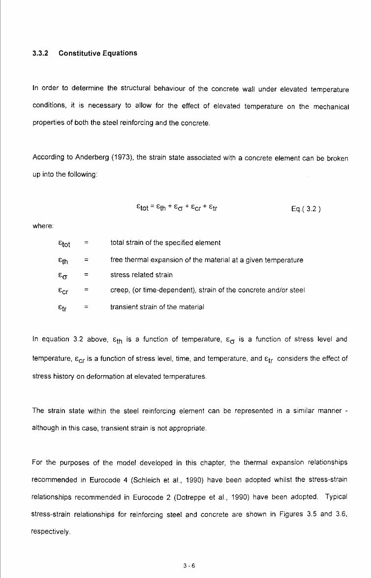
3.3.2 Constitutive Equations
In order to determine the structural behaviour of the concrete wall under elevated temperature
conditions, it is necessary to allow for the effect of elevated temperature on the mechanical
properties of both the steel reinforcing and the concrete.
According to Anderberg (1973), the strain state associated with a concrete element can be broken
up into the following:
etot = sth + Sa + ^cr + str
where:
Sfot
Hh
Ear
etr
Eq.( 3.2 )
total strain of the specified element
free thermal expansion of the material at a given temperature
stress related strain
creep, (or time-dependent), strain of the concrete and/or steel
transient strain of the material
In equation 3.2 above, St^ is a function of temperature, 8^ is a function of stress level and
temperature, EQJ- is a function of stress level, time, and temperature, and Sfp considers the effect of
stress history on deformation at elevated temperatures.
The strain state within the steel reinforcing element can be represented in a similar manner -
although in this case, transient strain is not appropriate.
For the purposes of the model developed in this chapter, the thermal expansion relafionships
recommended in Eurocode 4 (Schleich et al., 1990) have been adopted whilst the stress-strain
relationships recommended in Eurocode 2 (Dotreppe et al., 1990) have been adopted. Typical
stress-strain relationships for reinforcing steel and concrete are shown in Figures 3.5 and 3.6,
respectively.
3 - 6

For concrete, the transient strain term, 8tr_ and the creep strain term, 8cr> have been implicitly (and
appropriately) included in the Eurocode 4 stress-strain relationships. Thus, only thenmal and stress
related strains are explicitly considered.
For steel reinforcement, creep effects are only significant for temperatures greater than 450 °C
(Williams-Leir, 1983).
Again, the creep effects are implicitly included in the Eurocode 4 stress-strain curves for steel. It is
important to note that Eurocode 4 recommends different stress-strain relationships for reinforcing
steels - depending on whether the steel is cold-worked or not. Reinforcing fabric is manufactured
from hard drawn wire and is most commonly used to reinforce concrete walls. It is rare that Y bars
are used.
Therefore the appropriate stress-strain relationships for steel reinforcement, for the analyses
undertaken in Chapter 4, are those corresponding to cold-worked reinforcing steel as shown in
Figure 3.5.
It has been assumed that use of the above European stress-strain relationships will give an
adequate representation of the elevated temperature behaviour of Australian materials.
3 - 7

^/ fay(20%)
8 ( 6 ) % 0 0.5 1.0 1.5 2.0
Figure 3.5 Stress-Strain Relationships for Reinforcing Steels at Elevated Temperatures
^/fc(20%)
Figure 3.6
e(e)%
Stress-Strain Relationships for Siliceous Concrete at Elevated Temperatures
The majority of concrete used in Australia in the manufacture of concrete walls use siliceous
aggregates. The relationships given in Figure 3.6 are therefore appropriate.
3 -8

3.3.3 Strain State within A Segment
Within any segment down the wall it is assumed that the deformation of the elements is such that
plane sections before deformation remain plane after deformation.
It is also assumed that the curvature within a segment is constant over the length of the segment.
With the strain state within a segment assumed to be constant, the stress state can be determined
through satisfaction of the equilibrium equations given below in Section 3.3.4.
3.3.4 Equilibrium Equations
The equilibrium situafion associated with a deformed wall is shown in Figure 3.7 and is described by
the following governing equations.
N D
j segment twundary
Figure 3.7 Equilibrium Equations for the Cantilevered Wall
where:
point adjacent to segment boundary about which moments are taken
element number
3 - 9

j = segment/boundary number
"i = total number of elements analysed
rij = total number of segments analysed
At each segment boundary the following equilibrium equations must be satisfied:
The Resultant Force, Fr, at the jt ^ segment boundary = 0 :
i.e. F, = 0
But, ^r=^mt-^exl Eqs. ( 3.3 )
Equating the above equations, we have:
Fr=feii|-|iWi+N M V {U ' J
= 0 Eq. ( 3.4 )
The Resultant Moment, Mr, at the jt^ segment boundary about 'a' = 0
M, = 0
But, M , = M i - M , Eqs. (3.5)
Equafing the above equations, we have:
M,=(|;Vy,)-(iw,.d,-P.h,.N.D] = 0 ^ ^ _ ^
For the wall to be in equilibrium each segment boundary must satisfy the above equations.
For the model described above, equilibrium was progressively checked at the various element
boundaries starting from the top of the wall and working downwards, (see Figure 3.7).
3-10

3.3.5 Compatibility Equations
In addition to the equilibrium equations, it was necessary to determine the relationships between
segment rotation, curvature and lateral displacement.
Given the curvatures of the wall at each of the segment boundaries, the deflected shape can be
determined using the following equations; see Figure 3.8.
2
\
" l
1 ^
^
tr k ^ PosmonT
P.*
S
• l \ \
e._ p . * . \ p ^ 4 , ^ \ 0
Figure 3.8 Geometric Relationships Between Successive Points on a Curve
where;
6 is the slope at the element boundary
^ is the curvature at the element boundary
p is the element length
V is the lateral displacement at the element boundary
The compatibility equations are expressed as follows:
3-11
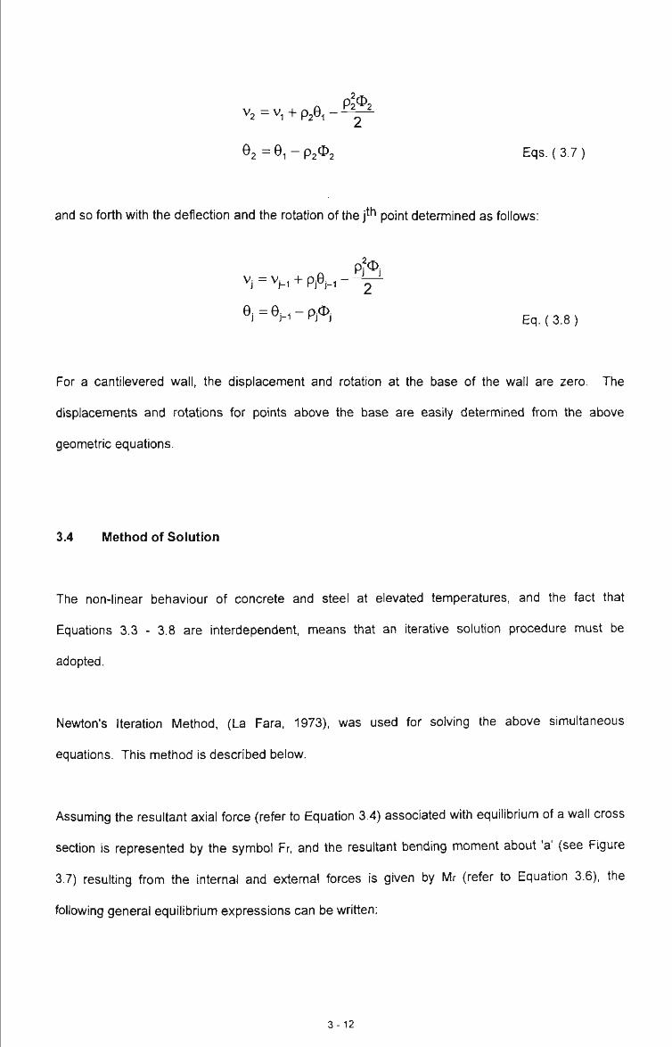
V 2 = V , + P A - ^
0 2 = 6 i - p 2 ^ 2 Eqs. (3.7)
and so forth with the deflection and the rotation of the f-^ point detennined as follows:
pfO,
® i = ^ H - P i ^ i Eq.(3.8)
For a cantilevered wall, the displacement and rotation at the base of the wall are zero. The
displacements and rotations for points above the base are easily determined from the above
geometric equations.
3.4 Method of Solution
The non-linear behaviour of concrete and steel at elevated temperatures, and the fact that
Equations 3.3 - 3.8 are interdependent, means that an iterative solution procedure must be
adopted.
Newton's Iteration Method, (La Fara, 1973), was used for solving the above simultaneous
equations. This method is described below.
Assuming the resultant axial force (refer to Equation 3.4) associated with equilibrium of a wall cross
section is represented by the symbol Fr, and the resultant bending moment about 'a' (see Figure
3.7) resulting from the internal and external forces is given by Mr (refer to Equafion 3.6), the
following general equilibrium expressions can be written:
3-12

where:
Fr(e.<t))=0
MXe,<|))=0 Eq. (3.9)
is the external surface strain of the segment j ; (see Figure 3.9 below)
is the curvature of the segment j ; (see Figure 3.9 below)
Wall Width = 150 mm
Figure 3.9 Locations of Initial Strain and Curvature Estimates at Segment j .
If e and ^ are the solutions, and e and ^^ are some initial estimates, then;
8 = 8 ^ + Ae
(t) = (j) ^ + A(t) Eq. (3.10)
Substituting equations 3.9 into equations 3.10,
F e ' + Ae , (|) ' + A(}))= 0
M,(8 ' + A8, (|) ' -h A(t))= 0 Eqs. (3.11 )
Using Taylor's series and ignoring terms that are of order greater than one, the following
approximate relations are obtained:
3-13

fdM
N(1) dR (1)
= 0
ae -H
Eqs. (3.12)
In order to obtain the above partial derivatives, three trials of initial strain (e), and curvature {^), were
undertaken to commence the iterative process. That is, three trials were undertaken to obtain a first
esfimate of partial derivatives (see Equation 3.14).
Trial 1
Trial 2
Trial 3
FiX^o. <t>o). MiXso. <l>o)
F je , , ( t ) „ -FA( t ) ) ,M j8„ . ( t . „ + A(|))
Fi (e,-hAe, ^^), M:(8, + A8. <j)„)
These first trials were then used to obtain partial derivatives as follows:
Eqs. (3.14)
SF,_F,3-F,,
6e Ae
8R F , -F i
8(|) A(|)
5M, M,^-M,^
5e Ae
5M, M,^-M;^
6(t) ~ A(t) Eq. (3.15)
Det = 8F^ 6M^_8F^ 8H 88 ' 8(t) ^ ' 8e
Eq. (3.16)
Values of Ae and A^ were obtained using Eq. ( 3.12 ) which when written in matrix form gives:
3-14

5e 5(j)
58 5<t) -
Ae
LA<t). -Fr
Eq.(3.17)
Substituting these estimates of As and A^ into Eq. ( 3.10 ) and inverting the above equation gives:
New £j^^ — eprev " 86 '' 86
Det
N e w (t)„e^ = (t)p,ev + ae ' ae Det
Eq. (3.18)
Eq. (3.19)
The entire process is repeated for each successive cycle of iteration (i.e., i > 2). The iterative
process is continued until negligible change occurs between successive cycles for calculated
displacements.
3-15

3.4.1 Analysis Procedure
The solution procedure is illustrated in Figure 3.7 and the computer coding is given in Appendix C.
INPUT ALL DATA RELATING TO GEOMETRY AND LOADING
DMDE WALL INTO ELEMENTS AND SEGMENTS
READ IN TEMPERATURES
DETERMINE "FREE THERMAL" STRAINS FROM TEMPERATURE DISTRIBUTION
FROM THERMAL STRAINS ASSUME AN INITIAL TOTAL
STRAIN LINE
Equations 3.3 - 3.6
PROPOSE A SET OF COMPATIBLE TOTAL STRAINS
<l cf. Sqiuaton 3.2
DETERMINE THE ELEMENT STRESSES AND STRAINS FOR 3 VARIATIONS
(TRIAL 1, TRIAL 2, TRIAL 3)
CfCiuBRiClM ^'^'^ I NEW TRIALS FOR STRAIN
-*<r^J!:i.I^LN »i AND CURVATURE FROM -X^rrERATIONS?^> » NEWTON-RAPHSON
CALCULATE SOLUTION OF STRAIN AND CURVATURE
FOR BOUNDARY, J
CHECK NEXT SEGMENT
ANALYSE WITH NEW DISPLACED SHAPE
YES CHANGE IN ^DISPLACED
^SHAPE?
NO
SOLUTION FOUND
STOP W-
YES T
Equations 3 9 • 3 19
Equations 3.7 • 3.8
Figure 3.10 Analysis Flow Chart for the Solution of the Wall Model
3-16
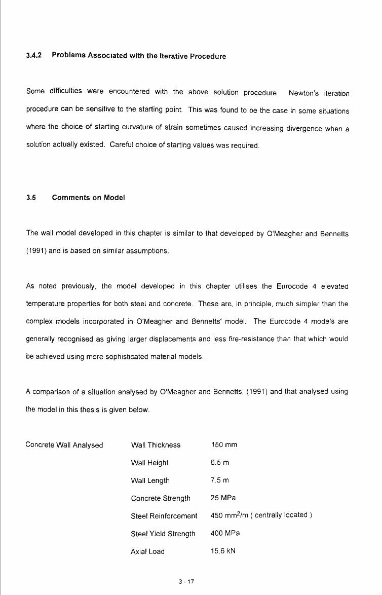
34.2 Problems Associated with the Iterative Procedure
Some difficulties were encountered with the above solution procedure. Newton's iteration
procedure can be sensitive to the starting point This was found to be the case in some situations
where the choice of starting curvature of strain sometimes caused increasing divergence when a
solution actually existed. Careful choice of starting values was required.
3.5 Comments on Model
The wall model developed in this chapter is similar to that developed by O'Meagher and Bennetts
(1991) and is based on similar assumptions.
As noted previously, the model developed in this chapter utilises the Eurocode 4 elevated
temperature properties for both steel and concrete. These are, in principle, much simpler than the
complex models incorporated in O'Meagher and Bennetts' model. The Eurocode 4 models are
generally recognised as giving larger displacements and less fire-resistance than that which would
be achieved using more sophisticated material models.
A comparison of a situation analysed by O'Meagher and Bennetts, (1991) and that analysed using
the model in this thesis is given below.
Concrete Wall Analysed Wall Thickness 150 mm
Wall Height 6.5 m
Wall Length 7.5 m
Concrete Strength 25 MPa
Steel Reinforcement 450 mm2/m ( centrally located )
Steel Yield Strength 400 MPa
Axial Load 15.6 kN
3-17

O'Meagher and Bennetts (1991) Bortoli (1995)
At 30 minutes SFT exposure: A « 975 mm A « 1076 mm
It can be seen that with the wall being uniformly heated over ifs entire length, the values of
displacement at the top of the wall compare quite favourably; i.e. <10% difference.
3.6 Conclusion
A numerical model for analysing the large displacement behaviour of concrete walls in fire has been
developed. The model utilises the "simplified" Eurocode 4 stress-strain relafionships for both
concrete and steel.
It is found to give conservative (i.e. larger) displacements than those associated with the model
developed by O'Meagher and Bennetts (1991).
3-18

CHAPTER 4 STUDY OF WALL DEFORMATIONS
4.1 Introduction
The purpose of this chapter is to further study the relationship between wall defonnations and fire
severity; ie. how far does the wall move laterally for a given fire exposure.
Through utilising the wall model developed in Chapter 3, a greater understanding of the magnitude
of deformations relating to various fire exposures is gained. Also the interaction between the lateral
restraining systems, including connections, and the deforming wall can be further understood.
The chapter examines the deformation behaviour of both unloaded and loaded concrete walls under
varying heat exposures and varying heights of exposure. The behaviour of both horizontal and
vertical panels is considered.
4.2 Vertical Panels
4.2.1 Unrestrained Wall Deformation - Self Weight Only
4.2.1.1 Introductory Concepts
In order to determine the structural response of a vertical wall element to fire, it is necessary to
study the behaviour of an unrestrained wall. In this case, the effects of thermal gradient and wall
self weight only, are taken into account with the walls analysed as cantilevered members.
Two levels of reinforcement have been considered for the analysis; the level specified in Section 11
- AS 3600 (the typical case) and twice this level. Hereafter, these walls are referred to as "typical
panels".
4 - 1

The relevant details for the wall panels considered are:
Wall Height
Wall Width
Wall Thickness
Concrete Grade, fc
Reinforcing Steel
Steel Yield Stress, fsy
End Conditions
External Loads
Load Eccentricity
6 m and 8 m
1000 mm
150 mm
32 MPa
1) Minimum Reinforcement;
Reinforcement Ratio, pw = 0.0015 %
=225 mm2/m
(as per AS 3600 Section 11).
2) Double Reinforcement;
Reinforcement Ratio, pw = 0.0030 %
=450 mm^/m
450 MPa
Free at the top, Fixed at the bottom
Lateral Load - optional
Axial Load - optional
Axial load is assumed to act centrally through the wall
Using the model developed in Chapter 3, the walls were subjected to varying levels of standard fire
exposure, with periods of exposure ranging from 2.5 to 90 minutes duration.
As noted previously (see Chapter 2), the characteristics of fires in warehouse buildings are highly
variable and, generally, will not resemble standard fire exposure conditions. The real fire time-
temperature curve and resultant wall exposure level is likely to be significantly different to those
associated with the standard fire test (SFT). Nevertheless, the gas time-temperature curve
associated with the standard fire test is convenientiy adopted to enable insight into aspects of wall
behaviour and evaluation of the relative importance of various factors.
4 - 2
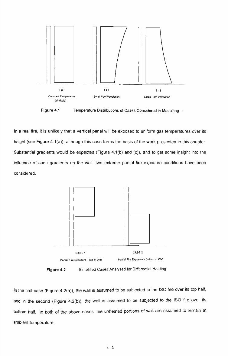
( a )
Constant Temperature (Unlikely)
( b )
Small Roof Ventilation
( c )
Large Roof Ventilation
Figure 4.1 Temperature Distributions of Cases Considered in Modelling
In a real fire, it is unlikely that a vertical panel will be exposed to uniform gas temperatures over its
height (see Figure 4.1(a)), although this case forms the basis of the work presented in this chapter.
Substantial gradients would be expected (Figure 4.1(b) and (c)), and to get some insight into the
influence of such gradients up the wall, two extreme partial fire exposure conditions have been
considered.
CASE1
Partial Fire Exposure - Top of Wall
CASE 2
Partial Pre Exposure - Bottom of Wall
Figure 4.2 Simplified Cases Analysed for Differential Heating
In the first case (Figure 4.2(a)), the wall is assumed to be subjected to the ISO fire over its top half,
and in the second (Figure 4.2(b)), the wall is assumed to be subjected to the ISO fire over its
bottom half. In both of the above cases, the unhealed portions of wall are assumed to remain at
ambient temperature.
4 - 3

4.2.1.2 Analysis Results and Discussion
The results of the above analyses are given in Tables 4.1 - 4.6 below.
Note: Shaded areas within the below tables indicate wall failure at these exposure conditions.
Tat
Reinforcement
Ratio; Pw
0.0015
0.0030
>le 4.1 Displacements for 6m Wall, Whole Wall Exposure; (mm)
Duration of ISO Fire Exposure; (min)
5
194
189
10
431
406
15
655
579
20
782
662
25
917
111
30
1054
111
60
-
1056
90
'-
1248
Table 4.2 Displacements for 8m Wall, Whole Wall Exposure; (mm)
Reinforcement
Ratio; Pw
0.0015
0.0030
Duration of ISO F
5
367
349
10
790
15
1199
20
1435
re Exposure; (min)
25
1802
30 60
-
90
Table 4.3
Reinforcement
Ratio; Pw
0.0015
0.0030
Displacements for 6m Wall, Top Half Wall Exposure; (mm)
Duration of ISO Fire Exposure; (min)
5
51
48
10
99
95
15
153
129
20
187
141
25
219
150
30
244
166
60
284
224
90
324
263
Table 4.4
Reinforcement
Ratio; Pw
0.0015
0.0030
Displacements for 8m Wall, Top Half Wall Exposure; (r
Duration of ISO F
5
85
83
10
187
174
15
285
243
20
357
118
re Exposure; (min)
25
431
317
30
489
336
nm)
60
559
461
90
637
511
4 - 4

Table 4.5
Reinforcement
Ratio; Pw
0.0015
0.0030
Displacements for 6m Wall, Bottom Half Wall Exposure; (mm)
Duration of ISO F re Exposure; (min)
5
135
132
10
288
269
15
433
366
20
538
403
25
633
429
30
706
475
60
827
650
90
944
762
Table 4.6 Displacements for 8m Wall, Bottom Half Wall Exposure; (mm)
Reinforcement
Ratio; Pw
0.0015
0.0030
Duration of ISO Fire Exposure; (min)
5
240
234
10
538
500
15
834
702
20
1044
812
25
1263
925
30
1441
985
60
1657
1356
90
1882
1509
Table 4.1 and 4.2 illustrate that the magnitude of displacement at the top of the wall increases with
increased level of ISO fire exposure. This displacement can be significant; (eg. 1802 mm after 25
minutes exposure).
Tables 4.1 and 4.2 show that for the 6 m wall, subject to full height ISO fire exposure, the fire-
resistance period achieved is 30 - 90 minutes depending on the reinforcement level. In the case of
the 8 m wall, the fire-resistance of the free-standing wall is only 5 - 25 minutes. As would be
expected, the maximum displacements attained for that of the 8 m high concrete wall panel are
larger than those of the 6 m high wall panel for the same fire-resistance level.
The 8 m wall panel has a lesser fire-resistance than the 6 m wall panel. These levels of fire-
resistance are well below the level of 90 minutes required for Type C construction; (see Chapter
2).1
Of greater significance is the fact that these walls will collapse outwards, (ie. away from the
building), if they are designed to act as free-standing members. This is exactiy what is intended to
be avoided by Clause C 1.11 of the BCA.
^ The wall panels, because of their thickness, will achieve the required levels of fire-resistance with respect to insulation and integrity. The above comment refers only to the matter of structural adequacy.
4 - 5

Tables 4.3 and 4.4 show the effect of varying the ISO fire exposure periods on the maximum lateral
displacements, assuming the walls to be subjected to heating of the top half of the wall, whilst
Tables 4.5 and 4.6 show this effect when the wall is subjected to heating of the bottom half.
As can be seen from the results given in Tables 4.3 and 4.4, the wall has no difficulty in obtaining a
fire-resistance level of 90 minutes when heated over the top half only. As expected, the magnitude
of displacements obtained for the case where the wall panel was heated over its top half was
significantiy less (typically 70-80% less), than the full height exposure case for corresponding fire
exposure times. A comparison of Table 4.1 and 4.5 shows that heating of the bottom half also
results in a significant increase in levels of fire-resistance (eg. for the minimum reinforced 6m wall
the fire resistance level increased from 30 minutes to more than 90 minutes).
Tables 4.5 and 4.6 show that the wall panels, when subject to bottom half heating only, are able to
achieve fire-resistances up to and including 90 minutes - the latter with maximum lateral
displacements up to 1882 mm. However, the displacements for a given fire exposure time are
greater than those for the corresponding "top half cases.
Although these analyses represent an approximate approach to determining the influence of vertical
variation of fire temperature on wall displacement, they illustrate how sensitive wall behaviour is to
such variation. By partially heating the wall, the maximum lateral displacements are reduced whilst
the level of fire-resistance is improved for a given fire duration.
The influence of a higher percentage of wall reinforcement on fire-resistance and wall displacement
can also be observed. Comparison of the results from Table 4.1 shows that the doubling of the
area of reinforcement in the wall results in an increase in fire-resistance from 30 minutes to 90
minutes. However, from Table 4.2 it can be seen that the increase in fire-resistance is not as
pronounced for the 8 m case as for the 6 m case. As would be expected, the maximum lateral
displacements achieved at the top of the wall prior to failure are less for the more highly reinforced
4 - 6

walls. For a given fire-resistance exposure time, doubling the amount of reinforcement reduces the
maximum lateral displacements at the top of the wall by between 2.5 - 5%.
The above analysis results illustrate that the presence of a temperature gradient up tiie wall height
will increase the fire-resistance of free-standing walls. Nevertheless, it is clear that ft-ee standing
walls of 8m height with minimum reinforcement (often the case) will not achieve high levels of fire-
resistance. Therefore, in the event of a large fire, it is quite possible that these walls will collapse
outwards (see Chapter 2). Therefore it is considered that these walls should be tied back to tiie
supporting frame.
It seems reasonable, therefore, to require vertical panels to be tied back to the supporting ft-ame
through adequate connection.
4.2.2 Restrained Wall Deformation - Self Weight and Lateral Load
4.2.2.1 Introductory Concepts
Restraint of a wall will result in lateral forces being applied at the top of the wall at the restraint
location.
Connection Between Precast Panel ' and Supporting Stnicture
Concrete Wall Panel -
Relative Lateral [displacement
Relative Lateral Displacement
~n r . Undisplaced Cotumn Position
Development of Cracking of / ^ Prying Force W fl Panel '
( a )
Position of structural Components
Pre-Fire Panel Orientation
( b )
Prying of Wall Panel
( c )
Cracking of Wall Panel
Post-Fire Panel Orientation
Figure 4.3 Cases Considered for Analysis of Restrained Wall Defonnation
4 - 7
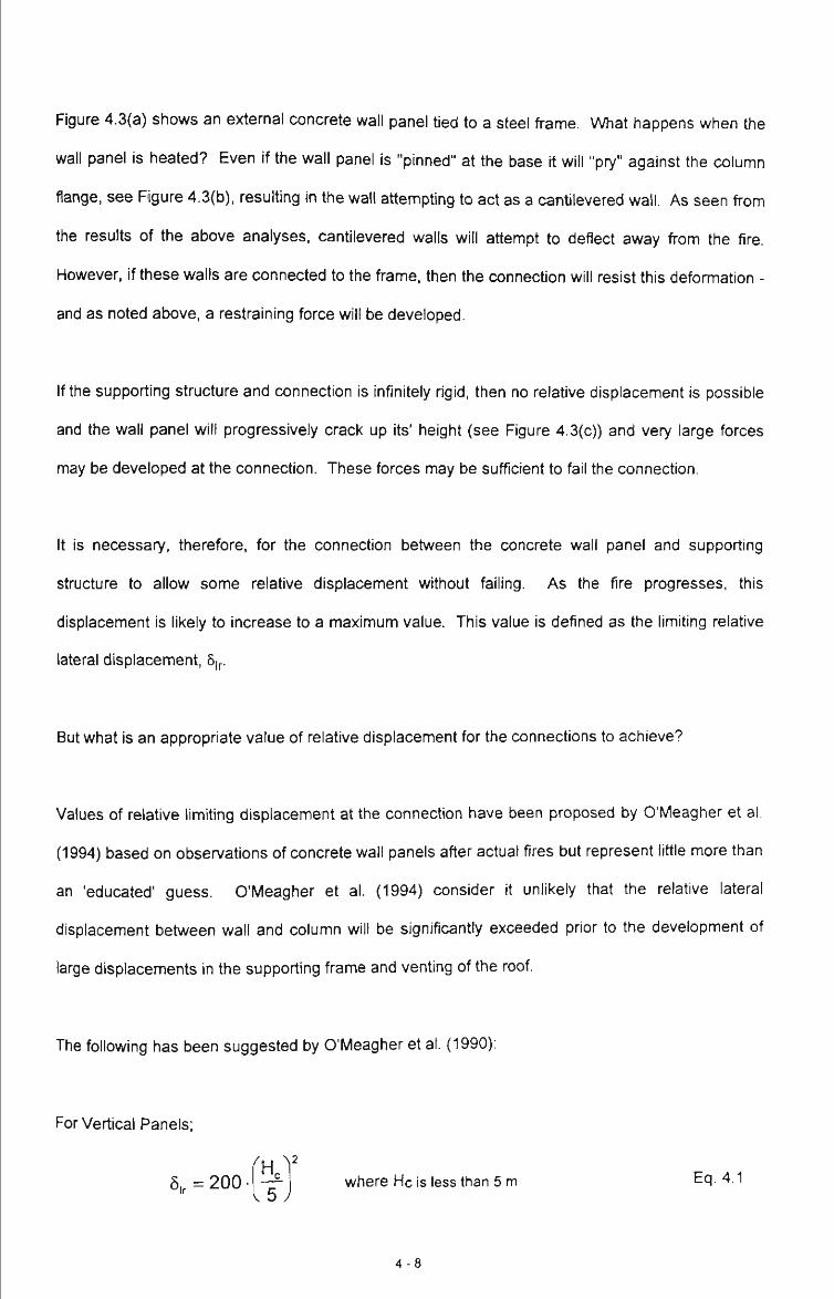
Figure 4.3(a) shows an external concrete wall panel tied to a steel ft-ame. What happens when the
wall panel is heated? Even if the wall panel is "pinned" at the base it will "pry" against the column
flange, see Figure 4.3(b), resulting in the wall attempting to act as a cantilevered wall. As seen ft-om
the results of the above analyses, cantilevered walls will attempt to deflect away from the fire.
However, if these walls are connected to the frame, then the connection will resist this deformation -
and as noted above, a restraining force will be developed.
If the supporting structure and connection is infinitely rigid, then no relative displacement is possible
and the wall panel will progressively crack up its' height (see Figure 4.3(c)) and very large forces
may be developed at the connection. These forces may be sufficient to fail the connection.
It is necessary, therefore, for the connection between the concrete wall panel and supporting
structure to allow some relative displacement without failing. As the fire progresses, this
displacement is likely to increase to a maximum value. This value is defined as the limiting relative
lateral displacement, 6|p
But what is an appropriate value of relative displacement for the connections to achieve?
Values of relative limiting displacement at the connection have been proposed by O'Meagher et al.
(1994) based on observations of concrete wall panels after actual fires but represent little more than
an 'educated' guess. O'Meagher et al. (1994) consider it unlikely that the relative lateral
displacement between wall and column will be significantly exceeded prior to the development of
large displacements in the supporting frame and venting of the roof.
The following has been suggested by O'Meagher et al. (1990):
For Vertical Panels;
6, = 200 - where He is less than 5 m Ecj. 4.1 V 5 y
4 - 8
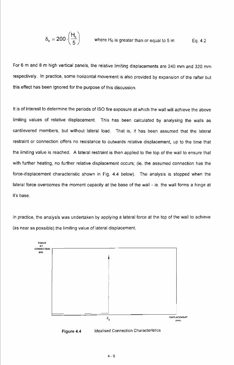
8„=200 ^H^ \5J
where He is greater than or equal to 5 m Eq. 4.2
For 6 m and 8 m high vertical panels, the relative limiting displacements are 240 mm and 320 mm
respectively. In practice, some horizontal movement is also provided by expansion of the rafter but
this effect has been ignored for the purpose of this discussion.
It is of interest to determine the periods of ISO fire exposure at which the wall will achieve the above
limiting values of relative displacement. This has been calculated by analysing the walls as
cantilevered members, but without lateral load. That is, it has been assumed that the lateral
restraint or connection offers no resistance to outwards relative displacement, up to the time that
the limiting value is reached. A lateral restraint is then applied to the top of the wall to ensure that
with further heating, no further relative displacement occurs; (ie. the assumed connection has the
force-displacement characteristic shown in Fig. 4.4 below). The analysis is stopped when the
lateral force overcomes the moment capacity at the base of the wall - ie. the wall forms a hinge at
it's base.
In practice, the analysis was undertaken by applying a lateral force at the top of the wall to achieve
(as near as possible) the limiting value of lateral displacement.
FORCE AT
CONNECTION (kN)
DISPUkCEMENT (mm)
Figure 4.4 Idealised Connection Characteristics
4 - 9

4.2.2.2 Analysis Results and Discussion
The results of the above analysis of cantilevered walls are summarised in Table 4.7. The walls
were assumed to be exposed to the ISO fire over tiieir entire height and incorporate a minimum
area (225 mm2/m) of reinforcement. It is also assumed that the connection to the wall from the
frame is at the top of the wall.
Table 4.7 Lateral Load Required to Maintain Critical Wall Deformation to 6ir.
Wall Height, (m)
SFT
Exposure
Duration;
(min)
7.5
7.5
10
6
Limiting 6|r = 240 mm
Lateral Load,
(kN)
0.00
0.75
Plastic Hinge at Base
Associated
A,
(mm)
306
251
Plastic Hinge at Base
8
Limiting 5ir = 320 mm
Lateral Load,
(kN)
0.00
1.25
Plastic Hinge at Base
Associated
A.
(mm)
600
355
Plastic Hinge at Base
From the above table it can be seen that with no lateral force applied to the top of the 6m wall, the
lateral displacement after 7.5 minutes of SFT exposure was 306 mm. The wall was then analysed
at this SFT exposure time with varying levels of lateral load with the solution being the one that
limited the wall displacement closest to that of the limiting 5|r. For the 6 m vertical wall panel to
maintain the limiting displacement, 5lr, of 240 mm after 7.5 minutes of SFT exposure, a lateral load
of approximately 0.75 kN must be applied at the top of the wall.
Similarly, for the 8 m vertical wall panel to maintain the limiting displacement, 8ir, of 320 mm a
lateral load of 1.25 kN must be applied by the supporting structure. The maximum horizontal force
applied to the top of the wall will only reduce the lateral displacements due to "elastic" behaviour by
18% of the total thermal displacement for the 6m case and 40% for the 8m case.
The results summarised in Table 4.7 illustrate a number of aspects of behaviour
4-10
• for the uniform heating situation assumed, the restrained 6 m and 8 m walls achieved the
limiting displacements proposed in Equation 4.1 in less than 10 minutes of standard fire
exposure. It is unlikely that the supporting frame will have undergone substantial deformation
when exposed to this duration of fire exposure. If the frame was subject to tiie ISO fire it would
generally take between 20 - 30 minutes of exposure to obtain very large displacements, as
steel temperatures in excess of 750 °C would be expected^. However, the nominated limiting
displacements (even allowing for 30 minutes of exposure) are the con-ect order of magnitude.
The calculated displacements are likely to be larger than those experienced in practice due to
the modelling assumption of one-way curvature, and the assumption of uniform heating up the
height of the wall.
• the application of force to limit the displacement to that given in Equation 4.1 resulted in the
bending moments at the base of the wall becoming equal to the wall's bending capacity. That
is, a "plastic hinge" at the base of the wall was formed.
• the level of force required to achieve a plastic hinge at the base of the wall is very low - 0.75 kN
for the 6 m wall and 1.25 kN for the 8 m wall.
4.2.2.3 Simplified Equilibrium Equations
Simplified expressions can be derived for the force likely to be developed in the connection between
concrete panels and the supporting steel portal frame. According to O'Meagher et al. (1994), if it is
assumed that the maximum relative displacement between panels and supporting frame at the
Portal frame structures are designed to resist dead and wind loads. Wind loading predominates but, In fire, the high presence of significant wind loads is not considered. Therefore the level of loading associated with a steel frame in a fire is that associated with dead loading. This is relatively low, and when given in tenms of Section 12 of AS 4100, a load ratio of less than 0.15. This load ratio translates to a temperature of 905-(690x0.15)«800''C. Thermally induced forces and moments will reduce this limiting temperature. Portal frame structures are constructed from members with a relatively low exposed surface area to mass ratio (ksm < 25). According to AS 4100, it would require fire exposure periods of up to 25 minutes to achieve a limiting temperature of 750 °C.
4 -11

height of the connection is 5ir, and that this relative displacement can be tolerated by the connection
system, then the maximum force at the connection can be estimated from:
[K+Tn-f jq Eq. 4.3
where:
W is the weight of the wall
6ir is the associated lateral displacement located at the top of the wall
Mb is the wall's ultimate moment capacity at the base
He is the distance from the connection at the top of the wall to the base of the wall
F is the lateral force induced at the connection at the top of the wall
The basis for the above expression is now explained. At the point in time when the steel frame
undergoes gross deformation, one side of the frame will attempt to pull the outwardly deforming
panel inwards. It is at this point that the maximum forces will be experienced by the connection
between the frame and the panels. The connection must overcome the base moment capacity (Mb)
of the wall and the P-6 displacements (see Figure 4.5). The above expression is conservative as in
reality it overestimates the force at the connection. It assumes that the application of F does not
reduce the outwards displacement 5 due to "elastic" deformations. As shown in the previous
section, "elastic" deformations of up to 40% of the total lateral displacement can be achieved with
the application of a force capable of achieving the moment capacity at the base of the wall.
4 - 1 2
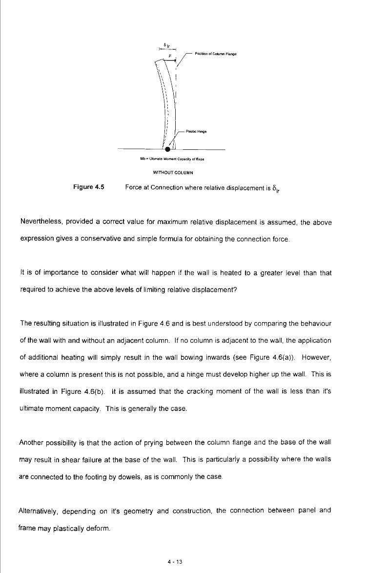
Poslion of Column Flange
Mb - Ultimate Moment Capacity of Base
WITHOUT COLUMN
Figure 4.5 Force at Connection where relative displacement is 5.
Nevertheless, provided a correct value for maximum relative displacement is assumed, the above
expression gives a conservative and simple formula for obtaining the connection force.
It is of importance to consider what will happen if the wall is heated to a greater level than that
required to achieve the above levels of limiting relative displacement?
The resulting situation is illustrated in Figure 4.6 and is best understood by comparing the behaviour
of the wall with and without an adjacent column. If no column is adjacent to the wall, the application
of additional heating will simply result in the wall bowing inwards (see Figure 4.6(a)). However,
where a column is present this is not possible, and a hinge must develop higher up the wall. This is
illustrated in Figure 4.6(b). It is assumed that the cracking moment of the wall is less than it's
ultimate moment capacity. This is generally the case.
Another possibility is that the action of prying between the column flange and the base of the wall
may result in shear failure at the base of the wall. This is particularly a possibility where the walls
are connected to the footing by dowels, as is commonly the case.
Alternatively, depending on it's geometry and construction, the connection between panel and
frame may plastically deform.
4 - 1 3
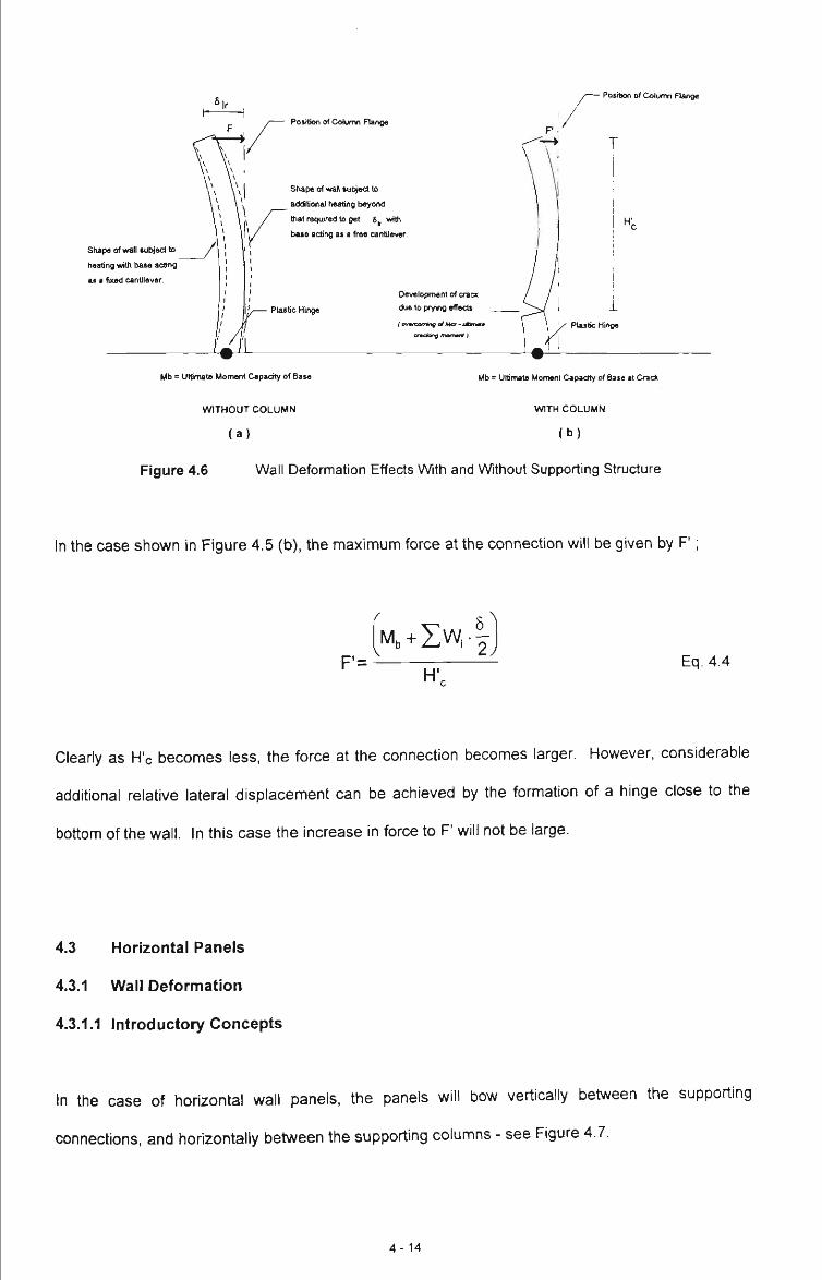
Shape of wall suliiect to
heating with t}ase acting
a i a fixed cantilever
Posiflon of Cotumn Range
Position of Cotumn Flange
St^pe of wan sutiject to
additional heating t>eyond
ttiat required to get 6, with
base acting as a free cantilevw.
Plastic Hinge
Development of crack
( ^ to prytrH) effects
(ovnxrnngafUcr-iJbnimta
cndtjng fnamurt)
Mb « Ultimate Moment Capacity of Base
WITHOUT COLUMN
( a )
Mb - Ultimate Moment Capacity of Base at Crack
WITH COLUMN
( b )
Figure 4.6 Wall Deformation Effects With and Without Supporting Stnicture
In the case shown in Figure 4.5 (b), the maximum force at the connection will be given by F';
F'= Eq. 4.4
Cleariy as H'c becomes less, the force at the connection becomes larger. However, considerable
additional relative lateral displacement can be achieved by the formation of a hinge close to the
bottom of the wall. In this case the increase in force to F' will not be large.
4.3 Horizontal Panels
4.3.1 Wall Deformation
4.3.1.1 Introductory Concepts
In the case of horizontal wall panels, the panels will bow vertically between the supporting
connections, and horizontally between the supporting columns - see Figure 4.7.
4 - 1 4
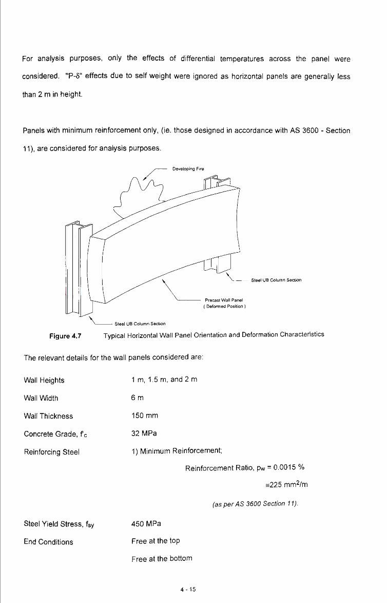
For analysis purposes, only the effects of differential temperatures across tiie panel were
considered. "P-5" effects due to self weight were ignored as horizontal panels are generally less
than 2 m in height.
Panels with minimum reinforcement only, (ie. those designed in accordance with AS 3600 - Section
11), are considered for analysis purposes.
Developing Fire
steel UB Column Section
Precast Wall Panel (Defomied Position)
Steel UB Column Section
Figure 4.7 Typical Horizontal Wall Panel Orientation and Deformation Characteristics
The relevant details for the wall panels considered are:
Wall Heights
Wall Width
Wall Thickness
Concrete Grade, f c
Reinforcing Steel
1 m, 1.5 m, and 2 m
6 m
150 mm
32 MPa
1) Minimum Reinforcement;
Reinforcement Ratio, pw = 0.0015 %
=225 mm^/m
(as per AS 3600 Section 11).
Steel Yield Stress, fsy
End Conditions
450 MPa
Free at the top
Free at the bottom
4-15
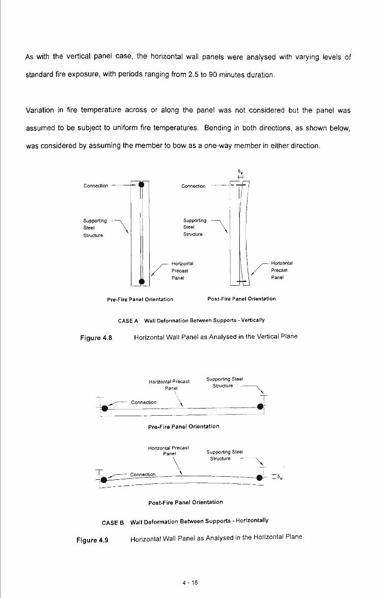
As with the vertical panel case, the horizontal wall panels were analysed witii varying levels of
standard fire exposure, with periods ranging from 2.5 to 90 minutes duration.
Variation in fire temperature across or along the panel was not considered but the panel was
assumed to be subject to uniform fire temperatures. Bending in both directions, as shown below,
was considered by assuming the member to bow as a one-way member in either direction.
Connection
Supporting Steel Structure
Connection
Supporting Steel Structure
Horizontal Precast Panel
^ ^
Horizontal Precast Panel
Pre-Fire Panel Orientation Post-Fire Panel Orientation
CASE A Wall Deformation Between Supports - Vertically
Figure 4.8 Horizontal Wall Panel as Analysed in the Vertical Plane
^
Horizontal Precast Panel
\
Supporting Steel Structure —
Connection \
Pre-Fire Panel Orientation
T
Horizontal Precast Panel Supporting Steel
Structure —
ConnecUon
" \
Post-Fire Panel Orientation
CASE B Wall Deformation Between Supports - Horizontally
Figure 4.9 Horizontal Wall Panel as Analysed in the Horizontal Plane
4-16

Case (A) shows the horizontal panel in the vertical plane. The panels were assumed to be
supported by four connections located at each of the panel comers. The effects of prying between
the typical clip connection, used in fixing such panels to structural steelwori , and the concrete
precast panel can be investigated through the analysis of this case.
Case (B) shows the wall as analysed in the horizontal plane. This analysis gives the maximum
central displacement as well as the rotation at the end of the panel; ie. the rotation imposed on the
connection by the panel rotation.
As for the vertical panel case, the connections must be adequately designed to cater for the relative
displacement and rotation arising from panel deformation. As noted previously, values for limiting
relative displacement at the connection have been proposed by O'Meagher et al. (1994), and for
horizontal panels are:
H, V 8 „ = 2 0 0 - Eq. 4.5
where Hf / 2 is less than 5 m.
A 5.=200(i Eq. 4.6
where Hf / 2 is greater than or equal to 5 m.
For the 1m, 1.5m and 2m high panels, the relative limiting displacements, according to the above
formulae, are 2 mm, 4.5 mm and 8 mm respectively.
The interaction of the clips with the deforming panel is now considered.
4 - 1 7
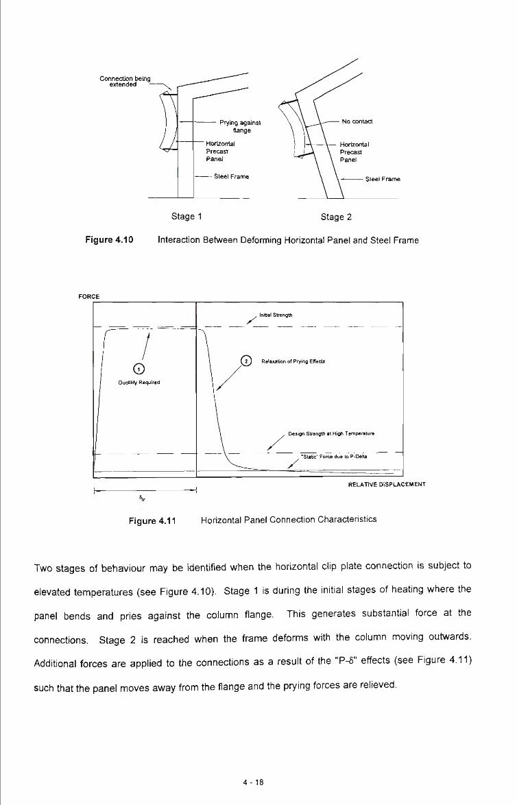
Connection being extended
Prying against flange
Horizontal Precast Panel
— Steel Frame
Figure 4.10
Stage 1 Stage 2
Interaction Between Deforming Horizontal Panel and Steel Frame
FORCE
1 1 o
1 Ductility Required
r
, Initial Strength
\ V L ) Relaxation of Prying EtTects
\ Design Stiangtti al High Temperature
\ •Static" Force due to P-Oella
REUVTIVE DISPLACEMENT
Figure 4.11 Horizontal Panel Connection Characteristics
Two stages of behaviour may be identified when the horizontal clip plate connection is subject to
elevated temperatures (see Figure 4.10). Stage 1 is during the initial stages of heating where the
panel bends and pries against the column flange. This generates substantial force at the
connections. Stage 2 is reached when the frame deforms with the column moving outwards.
Additional forces are applied to the connections as a result of the "P-5" effects (see Figure 4.11)
such that the panel moves away from the flange and the prying forces are relieved.
4 - 1 8
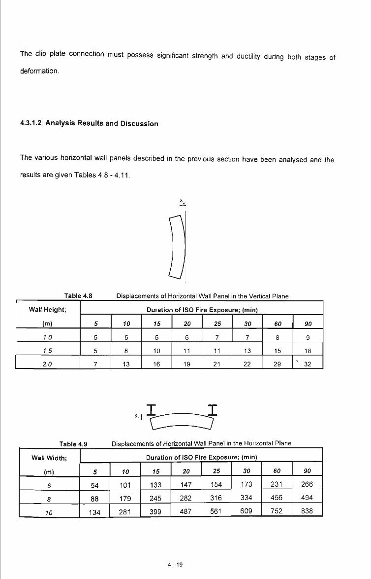
The clip plate connection must possess significant strength and ductility during both stages of
deformation.
4.3.1.2 Analysis Results and Discussion
The various horizontal wall panels described in the previous section have been analysed and the
results are given Tables 4.8-4.11.
U Table 4.8
Wall Height;
(m)
1.0
1.5
2.0
Displacements of Horizontal Wall Panel n the Vertical Plane
Duration of ISO Fire Exposure; (min)
5
5
5
7
10
5
8
13
15
5
10
16
20
6
11
19
25
7
11
21
30
7
13
22
60
8
15
29
90
9
18
^ 32
Table 4.9
Wall Width;
(m)
6
8
10
Displacements of Horizontal Wall Panel in the Horizontal Plane
Duration of ISO Fire Exposure; (min)
5
54
88
134
10
101
179
281
15
133
245
399
20
147
282
487
25
154
316
561
30
173
334
609
60
231
456
752
90
266
494
838
4-19

'^X^=J Table 4.10 Rotations of Horizontal Wall Pane
Wall Width;
( m )
6
8
10
in the Horizontal Plane (Degrees)
Duration of ISO Fire Exposure; (min)
5
1.6
2.1
2.7
10
3.3
4.6
5.9
15
4.5
6.4
8.5
20
5.0
7.4
10.4
25
5.3
8.4
12.0
30
5.9
8.8
13.1
60
8.1
12.1
16.2
90
9.3
13.2
18.0
Table 4.11 Displacements at the Connection Associated with Rotations in Table 4.9
Wall Width;
( m )
6
8
10
Duration of ISO Fire Exposure; (min)
5
2
2
3
10
3
5
6
15
5
1
9
20
5
8
11
25
6
9
13
30
6
9
14
60
9
13
17
90
10
14
19
From Table 4.8, it can be seen that for the horizontal panels when analysed in the vertical plane,
the limiting displacements at either edge of the panel vary with panel height as well as with ISO fire
exposure level. By increasing the horizontal wall panel height from 1m to 1.5m the relative
displacement doubled. By increasing the horizontal wall panel height from 1m to 2m the relative
displacement tripled. These results show that the height of the wall panels affects the level of
relative displacement for all of the ISO fire exposure levels analysed.
Table 4.9 shows the effect of increasing the wall width from 6m to both 8m and 10m. The
displacements are not greatiy affected at the lower levels of ISO fire exposure but with higher
exposure levels the displacements change quite drastically. By changing the effective wall width
from 6m to 8m the change in relative displacement is of the order of 1.5 - 2 times the 6m
displacements. By changing the effective wall width from 6m to 10m the change in relative
displacement over all fire exposures is of the order of 2.5 - 3.2 times the 6m displacements.
4 -20

Table 4.10 gives the rotations associated with the horizontal bending of the panels. This is quite
useful as it allows the total relative displacement that must be accommodated by the clip connection
to be determined. Table 4.11 gives the relative displacements associated with rotation at the
connections. The total values of relative displacement that the connection must withstand are equal
to the sum of those given in Table 4.8 and 4.11. It should be noted that these total values of
relative displacement are four times greater than those given by Equation 4.5 at a fire-resistance
level of 20 - 30 minutes. The calculated values are likely to overestimate tiie actual displacements
due to the conservative nature of the model (one-way bending assumed in both directions) and the
assumption of uniform heating of the panel. Despite this, however, it would appear that the total
relative displacements may well be greater than those given by Equations 4.5 and 4.6.
4.3.1.3 Simplified Equilibrium Equations
Assuming that the prying effects have been relieved, as discussed in Section 4.3.1.1, it is
necessary for the connections to resist the forces resulting from the "P-5" effects associated with
the outwardly deforming column.
where:
W
F
V ^ Note: 4 connections per Panel; (2 at the top, 2 at the bottom)
Figure 4.12 Deformed Horizontal Wall Panel Orientation
is the self-weight of the wall section considered
is the force at the top connection
4-21
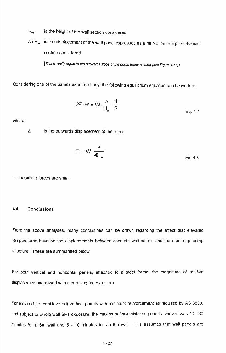
Hw is the height of the wall section considered
A / Hw is the displacement of the wall panel expressed as a ratio of Oie height of the wall
section considered.
[77J/S is really equal to the outwards slope of the portal frame column (see Figure 4.10)]
Considering one of the panels as a free body, the following equilibrium equation can be written:
A H' 2FH ' = W
Hw 2 Eq. 4.7
where:
A is the outwards displacement of the frame
P = W. ^ 4H, Eq. 4.8
The resulting forces are small.
4.4 Conclusions
From the above analyses, many conclusions can be drawn regarding the effect that elevated
temperatures have on the displacements between concrete wall panels and the steel supporting
structure. These are summarised below.
For both vertical and horizontal panels, attached to a steel frame, the magnitude of relative
displacement increased with increasing fire exposure.
For isolated (ie. cantilevered) vertical panels with minimum reinforcement as required by AS 3600,
and subject to whole wall SFT exposure, the maximum fire-resistance period achieved was 10-30
minutes for a 6m wall and 5 - 1 0 minutes for an 8m wall. This assumes that wall panels are
4 -22

exposed to uniform heating over their entire internal area. However, in practice, it is considered
unlikely that wails will be subject to such uniform heating.
To further investigate the likely influence of non-uniform heating, the behaviour of the wall panels
subject to non-uniform heating was examined, and it was shown that the fire-resistance of the walls
considered could be increased by up to 50% if the panel was subject to unifonn heating over only
half the height.
It was found that cantilevered walls will ultimately collapse outwards unless restrained by the steel
frame.
The behaviour of the typical vertical wall panels when restrained at the top was studied, using the
model developed in Chapter 3. It was found that the restraint force reached a value capable of
forming a plastic hinge at the base of the wall, after a standard fire exposure period of only 10
minutes for both 6m and 8m walls.
During the stages of a fire, before the frame undergoes gross-deformation, the frame will hold the
panel in position. Due to the outwards displacement of the wall there will be some relative
displacement between the wall and the frame. Any connection between the panel and the frame
must be able to absorb this relative displacement or resist an increasing force as the panel bends
against the column flange.
Approximate values have been suggested by O'Meagher et al. (1994) for these relative
displacements that may develop between the supporting steel frame and the concrete wall panels
during fire; (refer to 4.2.2.1 and 4.3.1.1). For vertical panels these are:
For Vertical Panels;
\=200 5) where He is less than 5 m.
4-23

6,^=200. fHc l -r- where He is greater than or equal to 5 m.
V 5 y
For vertical panels, it was found that the above values of relative lateral displacement were
achieved by the restrained panels when subject to full height fire exposure in less Uian 10 minutes.
It is unlikely that significant frame deformation resulting in the walls being pulled over would occur in
less than 20 - 30 minutes of standard fire exposure. Nevertheless, the limiting displacements
recommended by the above formulae are of the correct order of magnitude. The calculated
displacements are likely to be larger than those in practice because of the assumption of single
curvature bending and uniform heating over the height of the wall.
If the curvature of the wall is increased to give relative displacements beyond assumed limiting
values, it was found that there are several possible outcomes.
( i ) The force may build up in the connection to such an extent that the connection feils.
( i i ) The force may increase slightiy and the connection may deform plastically at high
temperatures - thus accommodating more wall deformation. This depends on the type of
connection.
(i i i) The force may increase slightly (<10%) with formation of a new hinge higher up the panel.
( iv) Due to prying of the concrete panel against the column flange, the panel may fail in shear
and move outwards at the base.
O'Meagher et al. (1994) recommends values for relative displacements between supporting
columns and clips.
For Horizontal Panels;
5, = 200 Uoj where Hf / 2 is less than 5 m.
4-24

8, =200 -^ where Hf / 2 is greater than or equal to 5 m.
From the analysis, assuming full fire exposure, it appears that the displacements may be up to four
times the value given by the above formula.
The interaction of horizontal panels with the supporting column was described and a simplified
expression for connection force derived.
4-25
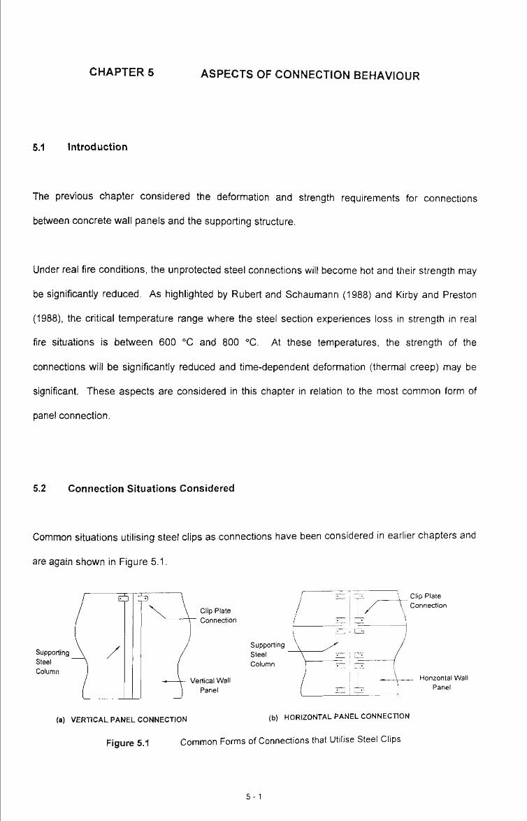
CHAPTER 5 ASPECTS OF CONNECTION BEHAVIOUR
5.1 Introduction
The previous chapter considered the deformation and strength requirements for connections
between concrete wall panels and the supporting structure.
Under real fire conditions, the unprotected steel connections will become hot and their strength may
be significantly reduced. As highlighted by Rubert and Schaumann (1988) and Kirby and Preston
(1988), the critical temperature range where the steel section experiences loss in strength in real
fire situations is between 600 °C and 800 °C. At these temperatures, the strength of the
connections will be significantly reduced and time-dependent deformation (thermal creep) may be
significant. These aspects are considered in this chapter in relation to the most common form of
panel connection.
5.2 Connection Situations Considered
Common situations utilising steel clips as connections have been considered in eariier chapters and
are again shown in Figure 5.1.
Supporting Steel Column
Clip Plate Connection
Supporting steel Column
Vertical Wall Panel
Clip Plate Connection
Horizontal Wall Panel
(a) VERTICAL PANEL CONNECTION (b) HORIZONTAL PANEL CONNECTION
Figure 5.1 Common Forms of Connections that Utilise Steel Clips
5 - 1

Eaves Tie
Supporting Steel Column
Clip Plate Connet^on
Vertical Wall Panel
(c) EAVES TIE CONNECTION
Figure 5.1 (continued) Common Forms of Connections that Utilise Steel Clips
Some initial comments on the situations shown in the above figure are warranted.
As discussed in the previous chapter, a vertical panel adjacent to a column section, will bow away
from the column under fire exposure and for cases (a) and (c), substantial relative displacements
between wall panel and column must be accommodated. In situation (a), it would appear that it is
unlikely that the clip will offer adequate strength and deformation capacity. In situation (c), the
expansion of the eaves tie may provide sufficient flexibility to allow the panel to bow away firom the
column due to expansion of the eaves tie and consequent buckling (see Figure 5.2); but will the clip
plate connection have sufflcient strength to hold the panel in position and then later participate in
pulling the panel inwards with the frame?
clip connection
clip connection
steel eaves tie member
deformation of eaves tie due to thermal expansion and buckling
Figure 5.2 System Capable of Minimising Prying Effects
Even for the horizontal panel shown in Figure 5.1(b), the clips will be defonned plastically due to
bowing of the panel and prying against the column flange (see Chapter 4).
The clip connection shown schematically in Figure 5.3 is representative of most clips used in this
form of construction, and is therefore worthy of investigation.
5-2

150 mm Thick Concrete Wall Panel
(Horizontal or Vertical Panels)
Universal Beam Section
Figure 5.3
250 Grade Clip Plate
High strength / Mild Strength Bolt
Typical Clip Plate Bearing Connection Used in Experimental Testing
In practice, the clip plate may or may not be welded to the column flange (or eaves tie in the case of
Figure 5.1(c)). The behaviour of both welded and non-welded clips are considered in this chapter.
The clip plate is generally of Grade 250 steel and has a length of 150 - 200 mm and a width of 100 -
150mm.
This type of connection generally utilises Grade 4.6 or Grade 8.8 bolts which are incorporated
within either 16 mm or 20 mm diameter ferrules. The ferrules used for the testing program utilised
Grade 8.8 bolts. It is important to note that sometimes expansion anchors are used in favour of the
ferrule connection.
The advantage of using the clip plate connection is that it is economical, it allows rapid erection and
fixing of the panels, and it does not require precise fit-up during construction.
5 - 3

5.3 Method of Approach
In order to study the behaviour of this type of connection, a series of isolated connection tests were
performed at ambient and elevated temperature conditions.
Eight tests were conducted with four tests being at ambient temperature and four at elevated
temperatures.
Ambient temperature tests were conducted to provide a basis for comparison with the behaviour
under elevated temperature conditions as well as to obtain the ambient temperature strength.
Also investigated in the series of tests was the influence of creep on the behaviour of the
connection at elevated temperatures. The elevated temperature tests were conducted at
temperatures of 600 °C and 800 °C.
A summary of the testing program is shown in Table 5.1.
Test Number
( # )
1
2
3
4
5
6
7
8
Fable 5.1 Summary of Testing Program
Clip Welded ?
(Yes/No )
No
No
No
No
Yes
Yes
Yes
Yes
Clip Temperature
( °C)
Ambient
Ambient
600
800
Ambient
Ambient
600
800
Test
Designation
NW20-1
NW20-2
NW600
NW800
W20-1
W20-2
W600
W800
5-4

All of the steel used in the construction and assembly of the connections was taken from the same
section of plate. This was done so that there would be minimal variance of the tensile properties
between the eight connections.
5.4 Test Set-Ups
The test specimens incorporated four identical concrete slabs with which the eight tests were
carried out. For some of the elevated temperature tests the slabs were able to be re-used as there
was no visible structural damage. The various structural components that were incorporated into
the test specimens are described in Table 5.2 below, (see Figure 5.4).
COMPONENT
CONCRETE
STEEL
Table 5.2 Descrip
DESCRIPTION
Slab
Beam
Plate
Bolts
Ferrules
Weld
ASPECT
Width
Length
Depth
28 Day Strength
Reinforcement
Designation
Size
Grade
Size
Grade
Size
Reinforcement
Grade
Type
Size
ion of Test Samples
CLASSIFICATION
Nominal
650 mm
650 mm
650 mm
32 MPa
F82 Mesh
410UB60
150x100x10
250 MPa
M16
8.8
M16
300 mm long Y12 Bar
8.8
E41XX - 6mm SP CFW
2 / 50 mm
CLASSIFICATION
Measured
649.75
650.50
500.00
46 MPa
F82 Mesh
410UB60
150x100x10
280 MPa
M16
8.8
M16
300 mm long Y12 Bar
8.8
E41XX - 6mm SP CFW
2 / 50 mm
Figure 5.4 gives a schematic description of the specimen tested.
5-5

136 40 60 89
6mmE4axXCI=W
o O
Grade 8.8 Mie Bolt 410UB60
/ " Un-welded Clip Plate
It ELEVATION
Grade 8.8 Mie Bolt 410UB60
/ " Welded aip Plate
! •
ELEVATION
UN-WELDED CLIP CONNECTION WELDED CUP CONNECTION
Figure 5.4 Details of Connection Samples Tested
In addition to the full scale connection tests, the stress-strain characteristics of the concrete used
for the slab was determined (Appendix E), as was the 28 day compressive strength. The yield and
ultimate strength of the steel plate used for the clips was also determined (Appendix E).
5.4.1 Construction of Slab Forms
The forms for the concrete slabs were constructed from steel. A single layer of F82 mesh was
located centrally, ie. equal concrete cover top and bottom, in the formwork and spaced to give
adequate cover using four bar chairs situated symmetrically within the slab. The ferrules had to be
embedded into the concrete with the right tolerances and this was achieved by supporting the
ferrules off an angle section that spanned the width of the formwork, as shown in Figure 5.5.
5-6
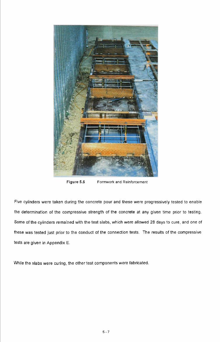
Figure 5.5 Formwork and Reinforcement
Five cylinders were taken during the concrete pour and these were progressively tested to enable
the determination of the compressive strength of the concrete at any given time prior to testing.
Some of the cylinders remained with the test slabs, which were allowed 28 days to cure, and one of
these was tested just prior to the conduct of the connection tests. The results of the compressive
tests are given in Appendix E.
While the slabs were curing, the other test components were fabricated.
5-7
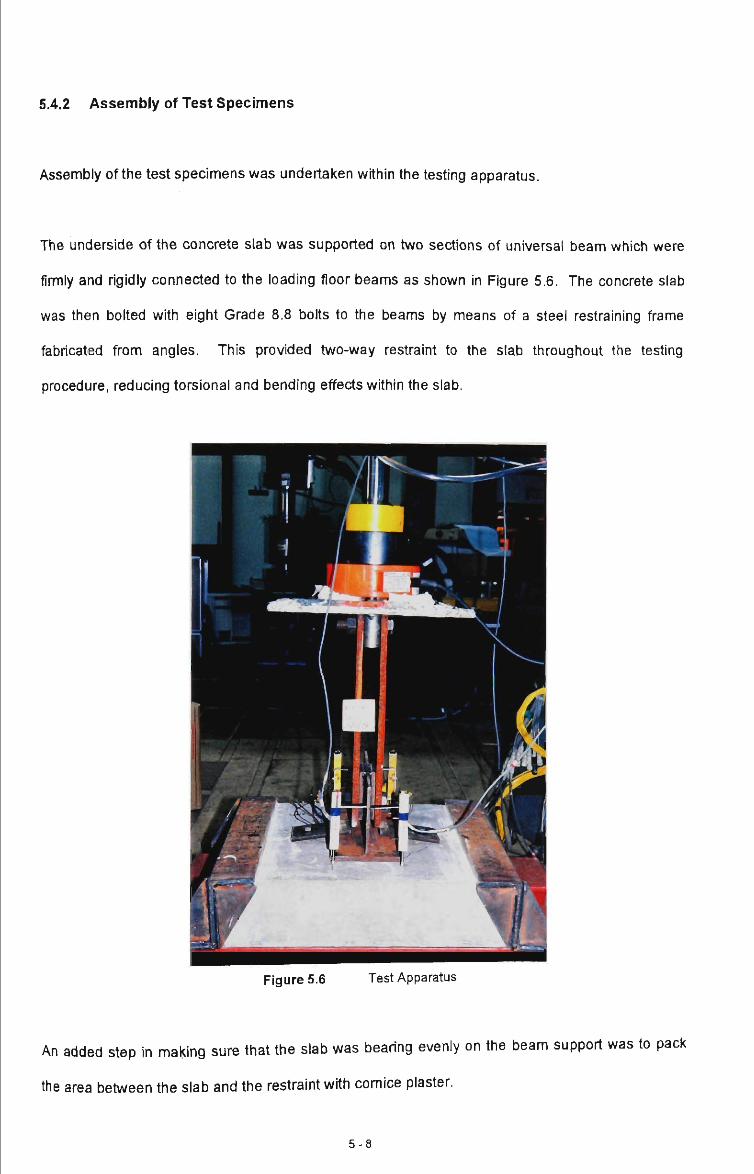
5.4.2 Assembly of Test Specimens
Assembly of the test specimens was undertaken within the testing apparatus.
The underside of the concrete slab was supported on two sections of universal beam which were
firmly and rigidly connected to the loading floor beams as shown in Figure 5.6. The concrete slab
was then bolted with eight Grade 8.8 bolts to the beams by means of a steel restraining frame
fabricated from angles. This provided two-way restraint to the slab throughout the testing
procedure, reducing torsional and bending effects within the slab.
Figure 5.6 Test Apparatus
An added step in making sure that the slab was bearing evenly on the beam support was to pack
the area between the slab and the restraint with cornice plaster.
5-8

The restraint limited the effects of torsion and bending on the slab and effectively held the system
rigid over all four edges of support.
Load was applied to the specimen by a tension jack via two plates connected to tiie web of the
460UB 'T ' section; (see Figure 5.6). The plates were bolted at one end to the web of tiie beam and
to the loading ram at the other.
Certain differences existed In the assembly of the steel components of the non-welded and welded
test samples. The differences are highlighted below.
5.4.2.1 Non-Welded Connection
In the non-welded case, the beam section was placed in the centre of the slab between the cast-in
ferrules. The clip plate, one on each side of the web, was bolted to the flange of the beam using a
single M16 Grade 8.8 bolt. The bolt was snug tightened to a torque setting of 400 Nmm as required
by AS 4100.
The clip plates used in the non-welded case were straight and only had one point of contact with the
beam flange, as shown in Figure 5.4.
5.4.2.2 Welded Connection
The welded connection was set-up in a similar manner to that described above with the beam being
situated between the cast-in ferrules. The main difference was that in this case, the clip plate was
purposely bent so that the plate had two points of contact; ie. along the slab and along the beam
flange. This was done to facilitate welding.
5-9
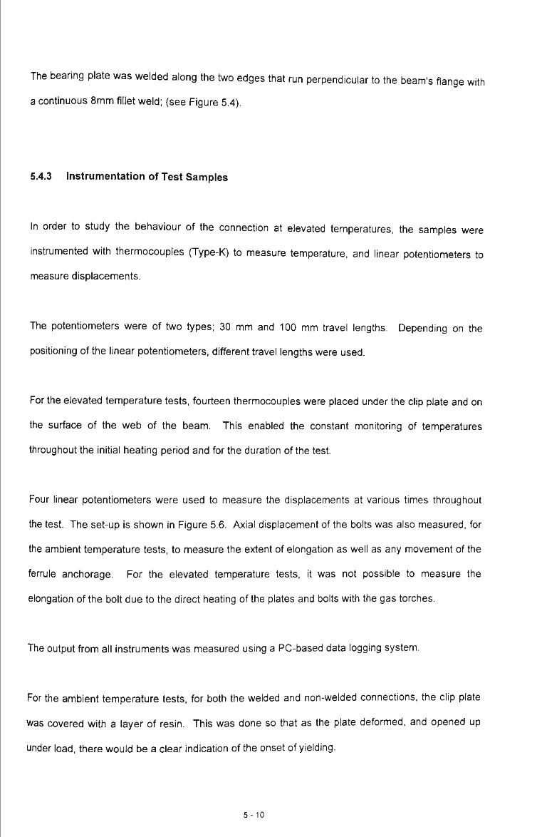
The bearing plate was welded along the two edges that run perpendicular to the beam's flange with
a continuous 8mm fillet weld; (see Figure 5.4).
5.4.3 Instrumentation of Test Samples
In order to study the behaviour of the connection at elevated temperatures, the samples were
instrumented with thermocouples (Type-K) to measure temperature, and linear potentiometers to
measure displacements.
The potentiometers were of two types; 30 mm and 100 mm travel lengths. Depending on the
positioning of the linear potentiometers, different travel lengths were used.
For the elevated temperature tests, fourteen thermocouples were placed under the clip plate and on
the surface of the web of the beam. This enabled the constant monitoring of temperatures
throughout the initial heating period and for the duration of the test
Four linear potentiometers were used to measure the displacements at various times throughout
the test The set-up is shown in Figure 5.6. Axial displacement of the bolts was also measured, for
the ambient temperature tests, to measure the extent of elongation as well as any movement of the
ferrule anchorage. For the elevated temperature tests, it was not possible to measure the
elongation of the bolt due to the direct heating of the plates and bolts with the gas torches.
The output from all instruments was measured using a PC-based data logging system.
For the ambient temperature tests, for both the welded and non-welded connections, the clip plate
was covered with a layer of resin. This was done so that as the plate deformed, and opened up
under load, there would be a clear indication of the onset of yielding.
5-10

5.5 Test Procedure
The forces were applied to the specimens using the jacking system shown in Figure 5.6. This
consisted of a single tension jack of 200 kN capacity, and load cell with the facility to conti-ol the rate
of ram movement. The jacking system was attached to a cross-head frame and mounted on the
reaction floor at the Melbourne Laboratories of BHP Research.
The connections were tested under both load and position control.
The ambient temperature tests were all conducted under position control. In this case, the force
applied at the connection was governed by the displacement of the loading ram. The ram
displacement was able to be controlled to a given pre-determined rate.
The elevated temperature tests, on the other hand, were tested under load control. This meant that
the loading of the connection was governed by incrementing the load at pre-determined times
during the test. This enabled the effects of connection creep to be studied. Details of the load and
temperature histories are given in Sections 5.6.3 and 5.6.4 for the non-welded and welded tests,
respectively.
The heating of the connections was facilitated using two gas torches, one on either side of the
beam web as shown in Figure 5.7.
5-11

Figure 5.7 Heating Up of Test Samples
This method of heating enabled the plate temperatures to be regulated to an accuracy ot30 °C, as
shown in Figure 5.8.
900 o
. 800 • O) 0)
Q 700 -
£ 600 -3 2 500 A 1 400 -|2 a 300 -? 200 -0) 2 100 -
0:0
0:0
0-
0:0
5:0
0-
0:1
0:0
0-
0:1
5:0
0.
Figi J re 5.
0:2
0:0
0.
8
300 C ""1 eg. k y •h
"kwww^ j ' * ^ ^ - T *
o o o o o o o o o o o o o o o o i f > d i i ) d i i ) d i i ) d 'y 'v'. 'P. "*. 'f ^. ^ '^ d d d d d d d < : - ^
Elapsed Time of Exposure, (min)
M ainter lance ofC ipPIs ite Te mpe •ature
-«»»•, n _ .
C 9 9
Ove
300 Deg. \ \
1:1
0:0
0.
1:1
5:0
0.
1:2
0:0
0.
rTimf 2
5-12

The gas torches were used to slowly and uniformly heat up the clip plate to a specified temperature
of either 600 "C or 800 °C, depending on the test. Once the target temperature was attained on
both of the connections, and seen to be adequately maintained, the loading of the specimens
commenced. The target temperature was held constant throughout the test
Because the plate was tested as an isolated component, the area sun-ounding the clip plate had to
be adequately protected and insulated ft-om heat. This was achieved using mineral wool (see
Figure 5.7). This also served as protection for the instrumentation situated close to the heated clip
plate.
5.6 Test Results and Discussion
A summary of the test results, including a description of the failure modes, is given in Table 5.4.
Each test is designated with a specific notation.
Test
Number
( # )
1
2
3
4
5
6
7
8
Test
Designation
NW20-1
NW20-2
NW600
NW800
W20-1
W20-2
W600
W800
Table 5.3
Maximum
Applied
Load
(kN)
35.0
35.0
10.5
1.5
84.5
109.8
55.0
13.0
Summary of Test Results
DEFLECTION
AT PEAK
LOAD
(mm )
27.9
29.1
14.8
15.6
11.4
17.5
32.7
36.9
DESCRIPTION
OF
FAILURE
MODE
Clips yield & open, Bolts deformed
Clips yield & open, Bolts deformed
Clips yield & open, Bolts deformed
Clips yield & open, Bolts deformed
Clips yield, Concrete cone failure
Clips yield, Concrete cone failure
Clips yield. Bolts deform & fail
Clips yield, Bolts deform & fail
Each test is now discussed in detail.
5-13

5.6.1 Ambient Test / Non-Welded Connection
The two ambient temperature tests of the non-welded clip connection were conducted to provide a
basis for comparison with the elevated temperature tests. As noted previously, the test was
conducted in position control. The rate at which the loading ram was displaced was 1 mm / min.
The resulting applied load versus displacement relationships are shown in Figure 5.9. It will be
noted that the load-displacement relationships for both tests are very similar.
•o (0 o - I •a .£ "5. a. <
10 15 20 25 30 Displacement, (mm)
35 40
Figure 5.9 Load Displacement Chart for Non-Welded Connections Tested at Ambient Temperature
Under the increasing tensile load, the clip plate was able to resist the force until approximately 27
kN when the plate experienced significant plastic deformation. In both tests, the maximum tensile
load that the connection was able to carry was approximately 35 kN, after which the connections
started to off-load. The deflection at this point was 25 - 28 mm.
As previously mentioned, a lacquer coating was applied to the top side of the clip plate to highlight
the areas on the plate should yielding occur. Most yielding (cracking of the lacquer coating) was
found to occur where the plate came into contact with the beam flange as shown in Figure 5.10.
5-14

Figure 5.10 Lacquered Clip Plate Under Strain
Eventually the clips opened up to such an extent that the beam pulled away from the slab (Figure
5.11).
Figure 5.11 Failed NW-20 Clip Plates
5-15
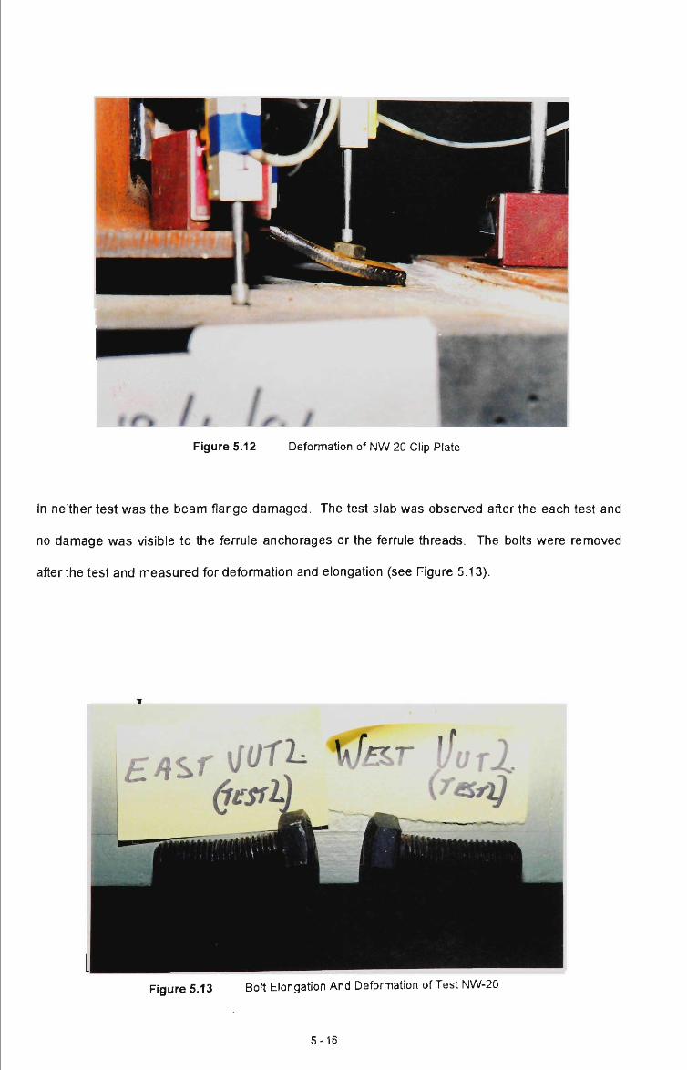
f r\ ft 1 r. I Figure 5.12 Deformation of NW-20 Clip Plate
In neither test was the beam flange damaged. The test slab was observed after the each test and
no damage was visible to the ferrule anchorages or the ferrule threads. The bolts were removed
after the test and measured for deformation and elongation (see Figure 5.13).
Ff{%r \}^'^^ ^^'^ ^^rl
Figure 5.13 Bolt Elongation And Deformation of Test NW-20
5-16
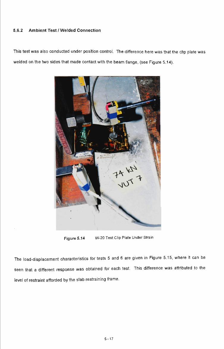
5.6.2 Ambient Test / Welded Connection
This test was also conducted under position control. The difference here was tiiat the clip plate was
welded on the two sides that made contact with the beam flange, (see Figure 5.14).
Figure 5.14 W-20 Test Clip Plate Under Strain
The load-displacement characteristics for tests 5 and 6 are given in Figure 5.15, where it can be
seen that a different response was obtained for each test. This difference was attributed to the
level of restraint afforded by the slab restraining frame.
5-17

120
100
80
I 60
••E 4 0
a <
20
0
/ \
l i . W20-2 -
^ \ W20-1
. (
1
0 20 40 60
Displacement, (mm)
80 100
Figure 5.15 Load Displacement Chart for Welded Connections Tested at Ambient Temperature
The first test was carried out with the slab being supported and restrained on two edges, (see
Figure 5.16). This set-up was used for the previous tests on the ambient/non-welded connections
and gave no indication of affecting the results.
^ ^ ^ ^ ^ ^
it- 1
(
1
riK* YI
^ ^ 1 / < 1
/ 1 1
) 1 ^ 1 / /
mjuial^
v | ' ' \
Figure 5.16 Premature Failure of W-20 Clip Plate
5-18

Failure in this case occurred at a peak force of just 85 kN with an associated deflection of
approximately 11 mm, (see Figure 17). Simple hand calculations, using the models given in
Appendix F, to check the capacity of the clip plate indicated that it was likely to have a significantly
greater capacity than 85 kN.
Figure 5.17 Premature Failure of Two-Way Support
Close examination of the slab revealed some flexural cracking and it was found that yielding of the
slab reinforcement had occurred between the supported edges directly under the UB section.
For the second test a modification to the test rig was made so that the edges of the test slab were
restrained on all four edges. This resulted in the slab resisting the connection forces through two-
way bending. This, in practice, will be the situation with a ferrule inserted into a wall.
5-19

The peak load experienced by the connections, in W20-2, was approximately 110 kN which
occurred at a deflection of approximately 18 mm. This figure compares well with that predicted
using simple design models - see Appendix F.
Test W20-2 finally failed by the ferrule pulling out of the concrete (see Figure 5.18). As can be seen
from this figure, a large cone of concrete was ripped out of the slab.
Figure 5.18 Proper Failure of W-20 Clip Plate Test
5.6.3 Elevated Test / Non-Welded Connection
The elevated temperature tests of the non-welded clip plate connection were conducted under load
control. This allowed the load-deflection relationships, with respect to time, to be attained. This is
important in assessing the likely influence of thermal creep on connection behaviour. The load was
increased in 0.5 kN increments.
5-20

The clip plate temperature-time relationships associated with NW600 and NW800 tests are similar
to those shown in Figure 5.8. The beam flange temperature was found to be significantiy lower
than the clip plate temperature which indicates the occurrence of heat loss fi-om plate to flange.
The displacement-time and applied load-time plots for tests 3 and 4 are given in Figures 5.19 and
5.20, for clip plate temperatures of 600 °C and 800 °C, respectively.
16 15 14 13
- 12-1 11 B 10 J
i 9 « 8 « I l 5 -" 3
2 1 0 J
c c c c c
I f i
t J r _ i
r
L
J
OA
r °i J
r , r 1
, 1 1
u
D
H
ISF 'L / Ci = M
/ f 1
PN
/ J ^
T-
-- 15 i 14 -- 13
12 - 11 Z
i 1 0 ^ - 9 -d - B o
- 7 -•
pli
-- 4 ^ 3 2
- 1 n
) 0 0 0 0 0 0 0 0 0 0 0 0 0 0 0 0 0 0 0 0 0 0 0 0 0 0 0 0 0 ) c o o c o o r ) o c o o o o r o o r o o r o o r o o c o o c o o r o o c o o c o o r o ) c M i o r > 0 ( M i o r ~ o e M i f l r ~ - o c M i n r > . o c N i r > r « o c > J i o r » - O P > 4 i n r ^ o c N ) O O O ' - ' - t - ' - c > i < M C M C N C 0 C 0 o r 0 ' t T t ' ^ T t i n m i n m o o o O ' - « -
E lapsed T i m e of T e s t , (min)
Figure 5.19 Creep Effects for Non-Welded Connection Tested at 600 °C
The time that the load was maintained at any one load setting was in the order of 2-3 minutes. If in
this time, no evident creep effects were noticed, then the load was incremented.
The level of stress in a steel member influences the load carrying capacity of the member and is
critical at temperatures of 600 °C and greater. Moriey and Royles (1979), state that the yield stress
of steel is reduced to 60% of the room temperature value at this elevated temperature. AS4100
suggests that the strength is reduced by 60%.
It will be noted that for test NW600, the rate of deformation increases as the load level is increased.
This reflects the fact that greater creep deformations will occur for higher load levels. It should also
5-21

be observed that the clip deformation at which separation of the clip and flange began to occur was
approximately 16mm. This was also the case with the ambient temperature tests; NW20-1 and
NW20-2.
In real fires, the clips may be subject to elevated temperatures for significant periods of time. Figure
5.19 illustrates that, unless the load level is kept low, significant time-dependent defonmations will
occur. For example, using the slope of the displacement-time relationship, if the load level required
in the real fire situation is 20% of the ambient clip strength, (ie. 7 kN), then failure by clip opening
would be expected after approximately 2 hours and 30 minutes. If the load level was 10% of the
ambient clip strength, (ie. 3.5 kN), then failure by clip opening would be expected after
approximately 4 hours and 30 minutes. On the other hand, if the load level was 5% of the ambient
clip strength, opening would be expected after approximately 14 hours at 600 °C.
These values of approximate time to failure are made on the basis of the following assumptions:
( a ) that there is a constant deformation rate for specified load level and
temperature and,
( b ) that there is a unique displacement at which failure occurs.
According the Fields (1989), creep strain varies linearly with temperature up to 600 °C, but at higher
temperatures the rate may increase with time. Knight (1972) also makes the assumption of linear
variation of creep strain with time. Assumption (a) is considered reasonable for the purpose of the
above calculations.
Failure of this connection specimen was directly attributed to the clip plate bending under the
increasing load at an elevated temperature. Both the bolt and plate lose strength and stiffness
under prolonged exposure at elevated temperatures, thus allowing the connection to deform and
bend. The bolts tended to elongate and deform as the plate yielded and opened.
5-22

It was recognised that at 800 °C, creep effects would be more significant. Lower levels of load were
applied, and at each load level, the load was maintained for generally longer periods.
From Figure 5.20, it can be again seen that as the level of load is increased, the rate of
displacement increases. Again, the value of displacement at which the clip plate opened to allow
separation of clip and flange was found to be approximately 16 mm. The displacement-time results
of Figure 5.20 indicate that at 800 °C, if a load level of 0.85 kN (2.5% of ambient sti-ength) was
applied to the clip, then separation would have occurred after approximately 30 minutes. If the load
level was increased to 5% of the ambient clip strength then separation would have occurred almost
immediately.
18 -17 -16 -15 -14 -
E 13 1 E 12 _ 11
p 10 -« 9 E 8 . 0) X o 7 J2 6 <o b ia 4
3 2 1 0 ^ c c
c c c
LOAD
IX*"^
DISPLACEMEN IT
0:0
2:3
0-
0:0
5:0
0-
0:0
7:3
0-
0:1
0:0
0-
m
.g
0:1
2:3
0-
(D ^ 0
:15
:00
-
»
0:1
7:3
0-
o -•<
? 0
:20:0
0
O c
0:2
2:3
0-
f 0
:25
:00
-
~'
0:2
7:3
0-
0:3
0:0
0-
0:3
2:3
0-
0:3
5:0
0-
1.8 - 1.7 . 1.6 . 1.5
1.4 1 . 3 -1.2 5
^ 1.1 ~ 1 "S 0.9 o 0.8 - ' 0.7 "g
t 0.6=5. - 0.5 Q. - 0.4 < - 0.3 - 0.2 [ 0.1
0
Figure 5.20 Creep Effects for Non-Welded Connection Tested at 800 °C
As noted previously, the non-welded clips eventually failed by separation from the flanges. The
same failure mode was noted under both ambient and elevated temperature conditions, (see Figure
5.21 and Figure 5.22). A small amount of rotation of the bolt heads was noted.
5-23
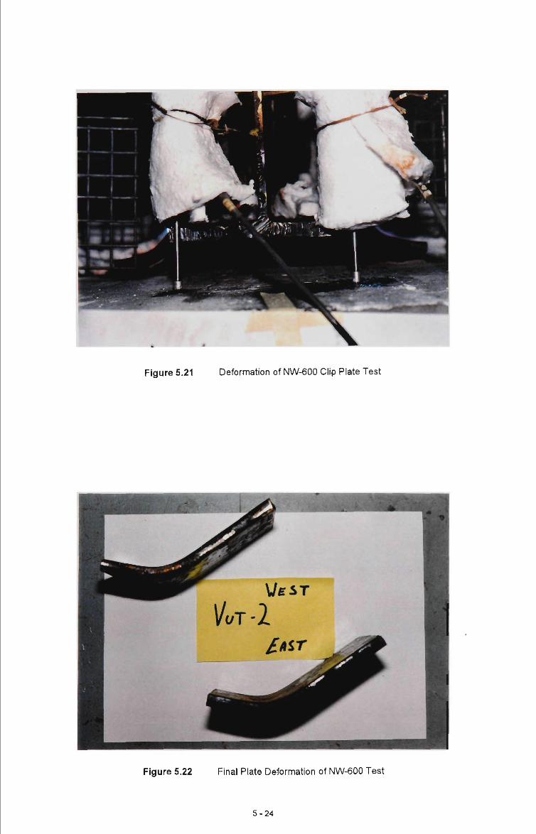
Figure 5.21 Deformation of NW-600 Clip Plate Test
Figure 5.22 Final Plate Deformation of NW-600 Test
5-24

5.6.4 Elevated Test / Welded Connection
As was the case for the non-welded tests, the connection specimens were heated to both 600 °C
and 800 °C (see Figure 5.8). Again, the clip temperatures were maintained to ±30 °C.
As for the non-welded connections tested at elevated temperatures, the load was increased in 0.5
kN increments. As would be expected, the welded connections, under elevated temperature
conditions offered significantly greater stiffness and strength than the non-welded connections.
The displacement-time and applied load-time plots for tests 7 and 8 are given in Figures 5.24 and
5.25, for clip plate temperatures of 600 °C and 800 °C, respectively. As observed in Section 5.6.2,
the welded connections did not fail under ambient temperature conditions by bolt failure, weld failure
or clip failure, but rather by pulling out of the ferrule from the concrete; ie. anchorage failure.
In contrast to the ambient temperature failure mode, the connections at elevated temperature failed
due to the stretching and bending of the bolt shank (see Figure 5.23). In the case of the welded
tests, the bolts were subject to much higher loads than the non-welded tests. The displacements
for both welded tests (W600 and W800), at failure due to a combination of bolt and clip deformation,
were 30 - 40 mm.
It is important to note, that in these tests, the bolt head was heated to the same temperature as the
clip plate.
5-25
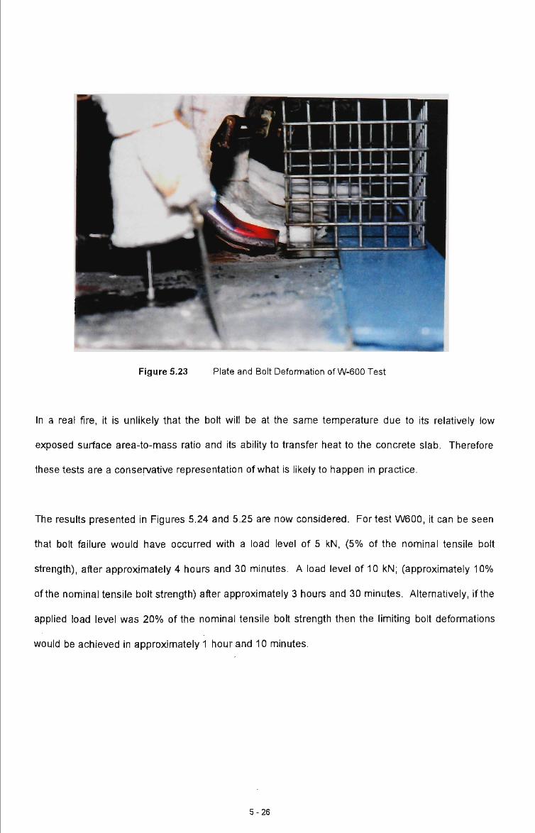
Figure 5.23 Plate and Bolt Deformation of W-600 Test
In a real fire, it is unlikely that the bolt will be at the same temperature due to its relatively low
exposed surface area-to-mass ratio and its ability to transfer heat to the concrete slab. Therefore
these tests are a conservative representation of what is likely to happen in practice.
The results presented in Figures 5.24 and 5.25 are now considered. For test W600, it can be seen
that bolt failure would have occurred with a load level of 5 kN, (5% of the nominal tensile bolt
strength), after approximately 4 hours and 30 minutes. A load level of 10 kN; (approximately 10%
of the nominal tensile bolt strength) after approximately 3 hours and 30 minutes. Alternatively, if the
applied load level was 20% of the nominal tensile bolt strength then the limiting bolt deformations
would be achieved in approximately 1 hour and 10 minutes.
5-26

E E
c E u Q. tn
a
80
70
60
50
40
30
20
10
o o 6 o 6
o o irj O
1 1
- L O A D -
H 1
i
1 1
ni
i
r
SPLACEMENT
o o
o o in
O O
CD CM
o o in CM
o o 6 CO
o o in CO
6
O o o
o o \Jn t
o o o
O O in in
O O 6 o
o o in o
o o
O t -
Elapsed Time of Test, (min)
80
70
60z
50"^ •o
40 J
20 3 10
0
Figure 5.24 Creep Effects for Welded Connection Tested at 600 °C
Some slight deformation of the bolt hole through the plate was noticed - see Figure 5.26. As the
clip was bent under the effects of both load and temperature, the bolt was subject to prying and
bending (see Figure 5.27). Failure eventually occurred when the bolt suddenly fractured through
the thread thus causing the beam section to come away from the slab. Failure was sudden and
occurred on one side of the column section with the opposite side failing immediately after, due to
the immediate transfer of load. Throughout the test the welds remained intact.
The results for the 800 °C test (W800) are now considered in detail (see Figure 5.25).
The maximum load experienced by the connection at 800 °C was approximately 13 kN with the
maximum deflection at this load being 37 mm.
5 - 2 7

Af\ . . 1 ^ ^•V
36 E 32 S 28 « 9A .
1 20 S 16 (0 a 12 -5 8 1
4 -(-1
o o o c o o o c O in o u-O O ' - r-o o o c
) c > c > c - c> > c
) O O O O O O O C > o o o o o o o c j i n o i n o i n o i n c j c v i c o c o ^ ' ^ i n i n c > 0 0 0 0 0 0 0 ' -
L
s^
O A D j
m£^
^ D SP .ACEMEN'
> o o o o o o o > o o o o o o o > in o in o in o in ) o <- »- CM CM CO en
Elapsed Time of Test, min)
1 ^^ —JL 1 Q ^T °
—f 1 4 ^ i 1 0 T^
1 -in o i "' 1 o T3
)lie
1 a 1 M- ^
-4 7 f o o o
1
Figure 5.25 Creep Effects for Welded Connection Tested at 800 °C
Again, failure was by stretching and bending of the bolt. Bolt failure occurred when the plate
separated from the slab, at the flange edge, by approximately 35 mm and occurred at a lower load
level than achieved for the W600 test. Compared with the W600 test, it can be seen that the rate of
displacement increased substantially for the same load level.
Figure 5.26 Failure of W-800 Test Showing Bolt Yielding
5-28

Based on a limiting relative displacement of 35 mm, it has been determined from Figure 5.25 that
failure would occur for a load level of 5 kN, (5% of the nominal ambient tensile bolt capacity), after
approximately 2 hours and 30 minutes and for a load level of 10 kN, (10% of nominal ambient
tensile boft capacity), after approximately 90 minutes. If a load level of approximately 20 kN, (20%
of the nominal tensile bolt capacity) was chosen, then failure would be almost immediate.
The clip plate gradually deformed under the effects from both temperature and load to the point
where the bolts failed. As was the case for the 600°C welded specimen, the bolts elongated and
failed quite suddenly through the bolt thread (see Figure 5.26 and Figure 5.27).
Figure 5.27 Bolt Deformation of W-800 Test
5-29

5.7 Conclusions
This chapter reports the results of ambient and elevated temperature tests on two types of
connections - non-welded clip plate connections and welded clip plate connections. These
connections are the most common in practice.
The following conclusions may be drawn from the tests reported in this chapter:
• Models for ambient temperature strength were proposed for estimating the likely strength of the
connections. These were found to correlate adequately with the test results.
• Under both ambient and elevated temperature conditions, the failure mode associated with the
non-welded clip was separation of clip and flange due to opening of the clip. For both ambient
and elevated temperatures this was found to occur when the clip displacement reached
approximately 16 mm. This displacement is unlikely to be sufficient to absorb the relative
displacement between horizontal panels and supporting frame, based on the likely relative
displacements calculated for such situations in chapter 4.
• Under ambient conditions, the welded clip connection failed by the ferrule being pulled out of
the concrete slab.
• Under elevated temperature conditions, the welded clip plate connection failed due to excessive
bolt deformation. For both 600 °C and 800 °C, a limiting combined plate plus bolt displacement
of approximately 35 mm was obtained. This will offer sufficient ductility for horizontal panels.
The use of a larger diameter bolt would improve the elevated temperature strength of the
connection, and this may be important for the support of vertical panels where higher forces
must be resisted.
5-30

• Welded connections are able to resist much greater load than the non-welded connections.
This is true for both ambient and elevated temperature conditions.
• Time dependent deformation increased with both temperature and load level. This was the
case for both types of connection.
• Approximate estimates of the time to failure at 600°C and 800 °C were made for various load
levels for both types of connection. The findings are as follows:
Table 5.4
Test Type
NW600
NW800
W600
W800
Estimated Time to Failure of the Elevated Connection Tests
Estimated Time to Failure; ( Hours, Minutes )
Percentage of Nominal Ambient Tensile Bolt Capacity; ( % )
5
14hrs
Immediate
4 hrs, 30 min
2 hrs, 30 min
10
4 hrs, 30 min
Immediate
3 hrs, 30 min
1 hr, 30 min
20
2 hrs, 30 min
Immediate
1 hr, 10 min
Immediate
• The welded connection is much more resistant to time-dependent deformations, at a given load
level and temperature, then the non-welded connection.
As far as the support of vertical panels is concerned, (Figure 5.1(a) and (c)), it is clear that neither
the welded or non-welded connection are capable of achieving, in themselves, the limiting relative
displacements between wall panel and column as discussed in Chapter 4. The maximum 'ductility'
offered by the welded connection, while still maintaining load, was about 35 mm. This is an order of
magnitude less than that likely to be required for vertical panels, but is likely to be satisfactory for
the support of horizontal panels.
5-31

Welded connections should only be used for vertical panels where they are used in combination
with another member which can provide for the relative displacement between panel and fi^me -
eg. an eaves tie member.
5-32

CHAPTER 6 CONCLUSIONS
This thesis has considered aspects of the behaviour of single storey industrial buildings consisting
of steel portal frames and external concrete wall cladding. Such buildings firequentiy have vertical
and horizontal concrete panels and these are connected to the steel supporting firame using a
variety of connection systems. As shown in chapter 2, most of the cun-ent connection systems
utilise a steel clip plate which is connected into the concrete panel and then to the supporting
member or frame. The behaviour of this particular connection is the subject of chapter 5.
Concern regarding the behaviour of such buildings in fire has resulted in clause CI.11 being
incorporated in the BCA. For buildings with external concrete walls, this clause requires buildings to
be designed such that, in the event of a fire, the wall panels will not collapse outwards. Various
design philosophies have been developed to achieve this outcome and these were reviewed in
chapter 2. ft was concluded that it is important that the wall panels remain firmly attached to the
frame throughout the fire.
In chapter 3, the development of a numerical model to study the behaviour of concrete wall panels
under fire conditions was developed. This model is based on several simplifying assumptions
including that of single curvature bending and that the elevated temperature behaviour of reinforcing
steel and concrete could be described by 'simplified' stress-strain relationships.
The model was found to give similar answers to those given by the more sophisticated model of
O'Meagher etal. (1991).
The model was used in chapter 4 to study the behaviour of isolated cantilever walls and walls that
are restrained at the top. ft was found that typical cantilevered walls with representative areas of
reinforcement could not achieve a fire-resistance of more than 30 minutes when exposed to a
standard fire over their entire height (6m case ). However, if the isolated walls were exposed to fire
6 - 1

only over part of their height, the fire-resistance was increased by as much as a factor of three.
Ultimately, isolated walls will collapse outwards.
For walls restrained at the top, it was shown that due to prying against the column flange, vertical
panels will behave as restrained cantilevers - irrespective of their base fixity details. Therefore as
the fire progresses inside a building, vertical panels will bow outwards - away from the column
flange. O'Meagher et al. (1994) have proposed fonmulae to give the maximum relative
displacement between a panel and its' supporting structure prior to collapse of the fi-ame. Using the
model developed in chapter 3, the behaviour of typical restrained vertical panels was studied, ft
was found, assuming full height fire exposure, that the relative displacements obtained fi-om
O'Meagher's formulae would be achieved after only 10 minutes of standard fire exposure. This was
noted as being significantly less than the 20 - 30 minutes of similar fire exposure required to cause
gross deformation. Nevertheless, it was concluded that the displacements obtained from
O'Meagher's formulae are likely to be of the correct order of magnitude - especially when it is
considered that the simplifying wall model assumption of single curvature bending has been made
and that ft is unlikely that a wall will be subject to uniform heating up its' height, ft is recommended
that some analysis be undertaken to determine the significance of the assumption regarding single
curvature bending.
Simplified expressions were given for the capacity of a connection if located at the top of a vertical
panel.
The detailed behaviour of horizontal panels attached to steel frames was also considered. Initially,
the clip connections may be subject to high forces due to prying of the panels against the column
flange. As the columns on one side of the frame move outwards, additional P-5 forces are
developed. This allows the prying effects to be relieved and the forces to be substantially reduced.
Based on statics and an assumed geometry, an expression for the magnitude of the final force on
horizontal connections was derived.
6 - 2

As noted previously, chapter 5 reports an extensive experimental program which looked at the
behaviour of the most common form of connection - the clip plate - under both ambient and
elevated temperature conditions. Two types of connections were considered; non-welded and
welded.
The non-welded clip failed by the clip opening up due to plastic deformation. This was true for both
ambient and elevated temperature conditions. The welded clip offered substantially greater
capacity at both ambient and elevated temperature conditions.
These tests illustrated the importance of creep and showed that time-dependent deformation
increases with increased temperature and increased load level. For design purposes, it is
necessary to keep the load level of the connection down to a sufficiently low level to minimise creep
deformations. Guidance can be obtained from the results of these tests and it would appear that, at
800 °C, the load ratio for the welded clip should be kept at around 0.05. This conclusion is likely to
also apply to other types of connections where (unlike the non-welded clip) the connection cannot
disengage as ft deforms. At 800 °C, it was found that the non-welded clip opened up and failed with
almost no load applied to it.
Neither the non-welded or welded clip plate connections were found to be able to achieve the
relative displacements between vertical panel and supporting frame as recommended by
O'Meagher et al. (1994). This is an important observation as this form of connection is commonly
used to connect vertical panels directly to the column flange. If this practise continues, it is likely
that such panels will collapse outwards away from the supporting frame.
Such connections can be used for vertical panels provided they are combined with a support
member (such as an eaves tie) which is capable of allowing for relative movement between panels
and frame.
6-3

Alternatively, the load-deformation information on welded clip plate connections could be used to
develop a specific connection which has sufficient strength and is capable of plastically deforming to
an appropriate level of relative displacement.
6 - 4

BIBLIOGRAPHY
1 Almand, K., "Fire Resistance Requirements in Building Regulations - An International
Comparison", Broken Hiii Proprietary Company Limited - Melbourne Research
Laboratories, August, 1989.
1. Anderberg, Y. and Thelandersson, S., "Stress and Deformation Characteristics of
Concrete at High Temperatures - 2. Experimental Investigation and Material
Behaviour Model", Division of Structural Mechanics and Concrete Construction, Lund
Institute of Technology, Bulletin 34, 1973.
3. Anderberg, Y. and Thelandersson, S., "Stress and Deformation Characteristics of
Concrete at High Temperatures - 1. General Discussion and Critical Review of
Literature", Division of Structural Mechanics and Concrete Construction, Lund Institute of
Technology, Bulletin 34, 1973.
4. Anderberg, Y., "Modelling Steel Behaviour", Fire Safety Journal, 13 (1988), pp. 17-26.
5. Australian Institute of Steel Construction,"Design Capacity Tables for Structural Steel",
1st Edition, 1991.
6. Australian Institute of Steel Construction, "Economical Structural Steelwork",>4usfra//an
Institute of Steel Construction, 3rd Edition, 1991.
1. Australian Standard, "Methods for Fire Tests on Building Materials, Components and
Structures - Part 4: Fire Resistance Tests of Elements of Building Construction",AS
1530.4-1990.
7-1

8. Australian Standard, "Tilt-up Concrete and Precast Concrete Elements for Use in
Buildings - Part 2: Guide to Design, Casting and Erection of Tift-up Panels", AS
3850.2-1990.
9. Australian Standard, "Tilt-up Concrete and Precast Concrete Elements for Use in
Buildings - Part 1: Safety Requirements", AS 3850.1-1990.
10. Australian Standard. "Methods of Testing Concrete - Methods for the Determination of
the Static Chord Modulus of Elasticity and Poisson's Ratio of Concrete Specimens",
AS 1012, Part 17-1976.
11. Australian Uniform Building Regulations Co-ordinating Council, Building Code of
Australia, 1990.
12. Bennetts, I.D., Proe, D.J., and Thomas, I.R., "Guidelines for Assessment of Fire
Resistance of Structural Steel Members", Australian Institute of Steel Construction, 1987.
13. BHP Steel, "Hot Rolled and Structural Products", 1991 Edition.
14. Bryan, E.R., "The Stressed Skin Design of Steel Buildings", Consfracfo Monographs,
1972.
15. Cement and Concrete Association of Australia, "Tilt-Up Technical Manual", July 1980.
16. CIB W14 Report., "Design Guide - Structural Fire Safety", [Based on a report entitled "A
Conceptual Approach towards a Probability based Design Guide for Structural Fire Safety, January 1983],
Fire safety Journal, Vol. 6, No. 1, 1983.
7 - 2

17. Constrado, "A Study of the Behaviour of Portal Frames in Fire When Subject to
Boundary Conditions", Advisory Services Fire Engineering Group, September 1979.
18. Constrado, "The Behaviour of Steel Portal Frames in Boundary Conditions",F/re and
Steel Construction Report, British Steel Corporation, April 1980.
19. Dotreppe, J.C, Krampf, L., and Mathez, J.,"Eurocode 2: Design of Concrete Structures
- Part 10 Structural Fire Design", Comm/ss/on of the European Communities, (Draft) April,
1990.
20. Fields, B.A. and Fields, R.J., "Elevated Temperature Deformation of Structural Steel",
National Institute of Standards and Technology, Report No. 88-3899, December, 1989.
21. Forrest, J.CM., "The Design of Industrial Buildings for Rational Fire Protection - The
Role of the Structural Engineer", The Concrete Society Limited, Technical Paper, London
1972.
11. Gillen, M., "Short-Term Creep of Concrete at Elevated Temperatures", Fire and
Materials, Vol. 5, No. 4, 1981.
23. Gnanakrishnan, N., "Likely Fire Performance of One and Two Storey Buildings with
Precast Concrete Tilt-Up Panels or Precast Concrete Cladding", CS/RO Division of
Building Construction and Engineering, Technical Report, Sydney 1993/2.
24. International Organisation for Standardisation 834,Fire Resistance Tests - Elements of
Building Construction, 1st Ed. 1985.
7 -3

25. Kirby, B.R. and Preston, R.R.,"High Temperature Properties of Hot-Rolled, Structural
Steels for Use in Fire Engineering Design Studies",F/re Safety Journal, 13 (1988), pp.
27-37.
26. Knight, D.C., "The Behaviour of Steel Structures in Fires",6HP Technical Bulletin, Vol.
16, No. 2, November, 1972.
11. LaFara, R.L., "Computer Methods for Science and Engineering",/nferfexf Books, USA,
1973.
28. Lie, T.T., "Structural Fire Protection: Manual of Practice", TTL/e Editor; Prepared by
the ASCE Committee on Fire Protection, American Society of Civil Engineers, 1992.
29. Malhotra, H.L., "Design of Fire Resisting Structures", Surrey University Press, London,
1982.
30. Moriey, P.O., and Royles, R., "The Influence of High Temperature on the Bond in
Reinforced Concrete", Fire Safety Journal, 2 (1979/80), pp. 243-255.
31. O'Meagher, A.J., and Bennetts, I.D., "Modelling of Concrete Walls in Fire", F/re Safety
Journal 17, 1991, pp. 315-335.
32. O'Meagher, A.J., Bennetts, I.D., Dayawansa, P.H., and Thomas, I.R.,"Design of Single
Storey Industrial Buildings for Fire Resistance", Australian Institute of Steel
Construction, Vol. 26, No. 2, May 1992.
7 - 4

33. O'Meagher, A.J., Bennetts, I.D., Dayawansa, P.H., and Thomas, I.R.,"Fire Protection of
Steel Framing - AUBRCC Research Project AP25", Broken Hill Proprietary Company
Limited - Melbourne Research Laboratories, December 1990.
34. O'Meagher, A.J., Bennetts, I.D., Hymas, I., and Stevens, B.,"Support of Extemal Walls in
Fire - An Engineering Approach", Draft Design Document, BHP Research - Melboume
Laboratories, Circulation Unrestricted, January 1994.
35. Occupational Health and Safety Act 1985, "Code of Practice - Tilt-Up Construction",
Department of Labour-Victoria, No.1, 1st October 1897.
36. Paulsson, M., "PRETEMP - Preprocessor for Finite Element Analysis of Non-linear
Transient Heat Conduction", Lund Institute of Technology, Sweden, Report TVSM-7011,
1983.
37. Rubert, A. and Schaumann, P., "Critical Temperatures of Steel Columns Exposed to
Fire", Fire Safety Journal, 13 (1988), pp. 39-44.
38. Schleich, J.B., Kruppa, J., Schaumann, P., and Twilt, L., "Eurocode 4: Composite
Structures - Part 10 Structural Fire Design", 1990
39. The Institution of Structural Engineers,"Design and Detaiing of Concrete Structures for
Fire Resistance", The Institution of Structural Engineers, London, April, 1978.
40. Twift, L., "Strength and Deformation Properties of Steel at Elevated Temperatures:
Some Practical Implications", Fire Safety Journal, 13 (1988), pp. 9-15.
\,.
7-5

41 . Wickstrom, U., "A Computer program for Temperature Analysis of Structures Exposed
to Fire", Lund Institute of Technology, Sweden, Report No. 79-2, 1983.
42. Wickstrom, U., "Temperature Calculation of Insulated Steel Columns Exposed to
Natural Fire", Fire Safety Journal, 4 (1981/82), pp. 219-225.
43. Williams-Leir, G., "Creep of Structural Steel In Fire: Analytical Expressions", Fire and
Materials, Vol. 7, No. 2, 1983.
44. Woodward, CD., "The Industrial Fire Problem", Fire Safety Journal, 15 (1989), pp. 348-
366.
45. Woolcock, S.T., Kitipornchai, S., and Bradford, M.A.,"Limit State Design of Portal Frame
Buildings", Australian Institute of Steel Construction, 1st Edition, 1991.
7-6

APPENDIX A CASE STUDIES
A1.0 Introduction
This appends presents a number of case studies of steel framed buildings that have been
subjected to significant fires in recent years. This is not an exhaustive study covering all fires, that
have occurred in such buildings, but is aimed at illustrating a number of behavioural aspects.
A2.0 Case Studies
Case 1 TFiANSPORT MANAGEMENT FACTORY
Mayne Nickless, (Melbourne 1992)
Construction - Construction consisted of steel portal frames with attached tilt-up vertical concrete
wall panels. The concrete panels were approximately 150mm thick and were 'pin-jointed' at the
bottom of the structure, and pursuant to AS3600, deemed to have an FRL equivalent to
240/240/240. The roof structure consisted of metal decking supported by steel roof puriins
spanning between the rafters. The floor area of the building was approximately 4200m2 and was
compartmented by a fire wall into two sections of approximately 2100m2 in area.
The concrete panels were connected directly to the outer flanges of column by welded clips and
dynabolts (see Figure 2.4). Similar connections were provided between the eaves tie member and
the panels except that in this case, the clips were not welded to the eaves tie (see Figure 2.6).
Regulatory Requirements - Pursuant to the BCA 1990, this building was deemed to comply
with the regulations and had a rise in storeys of one (1) and was of Type C construction. However
due to each compartment having an area of 2100m2, Type B construction was required in
accordance with Table C2.2 of Specification C1.1.
A-1

Fire Load - The contents of the building was diverse in type and quantity and included: calcium
hypochlorite (60-70 tonnes), hydrochloric acid (4 tonnes), cooking oil (100 tonnes), white goods,
metal ware, general consumer goods.
Fire Initiation and Spread - Fire initiated in one compartment and spread into the adjacent
compartment by means of a fire door that had been left open. There was no fire spread to adjacent
buildings primarily due to adequate separation provided by the external walls of the fire affected
building and adjacent buildings as well as the actions of the attending fire fighting crews. The fire
burned for more than six hours.
Building Behaviour - Throughout the course of the fire, several tilt-up concrete wall panels
moved inwards and outwards, (mostly inwards), with the majority of the remainder of panels leaning
precariously in both directions. Observation of the building after the fire indicated that the dynabolts
connecting the panels to the column clips had been pulled out of the concrete, and that the clips
connecting the panels to the eaves tie member has either grossly deformed or rotated, permitting
separation of panel and supporting structure.
Figure A.1 Case 1 - Mayne Nickless Storage Warehouse
A-2

Figure A.2 Case 1 - Mayne Nickless Storage Warehouse
Figure A.3 Case 1 - Mayne Nickless Storage Warehouse (Melboume, 1992)
A-3
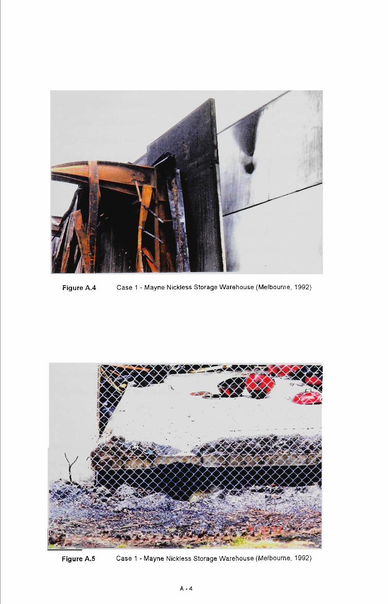
Figure A.4 Case 1 - Mayne Nickless Storage Warehouse (Melbourne, 1992)
Figure A.5
A-4

Case 2 PAINT STORAGE WAREHOUSE
Colortron Pty Ltd, (Melbourne 1987)
Construction - Construction consisted of a steel portal frame with attached precast horizontal
concrete wall panels. The concrete wall panels were approximately 150 mm thick and were
connected to the steel portal frame via a series of clip connections (see Figure 2.4). The roof
structure consisted of steel sheeting supported by steel puriins. The floor area of the building was
approximately 1670 wi^ which consisted of factory and office space.
Regulatory Requirements - Pursuant to the now replaced VBR's (Victorian Building
Regulations), this building was classed as a two storey building and the minimum type of
construction required for this building was Type 5. The building was of mixed class of occupancy -
Class V (office) and Class VIIIB (warehouse).
Fire Load - The exact quantity and type of goods stored within the building was not able to be
established with accuracy but ft is known that the goods included a substantial quantity of paints
and industrial strength solvents.
Fire Initiation and Spread - There was no flre spread to adjacent buildings primarily due to
adequate separation provided by the fire-resistant walls and the actions of the attending fire fighting
crews.
Building Behaviour - As can be seen from the following photographs showing the post-fire
results, the steel roofing membrane collapsed under it's own self-weight through loss of strength at
elevated temperatures. This behaviour resufted in the supporting columns being pulled inwards.
The clip connections between the precast concrete wall panels and the supporting steel frame and
failed throughout the course of the fire. These clip connections were not welded to the column
flanges.
A-5

Figure A.6 Case 2 - Colortron Paint Storage Warehouse (Melbourne, 1987)
Figure A.7 Case 2 - Colortron Paint Storage Warehouse (Melbourne, 1987)
A-6

Figure A.8 Case 2 - Colortron Paint Storage Warehouse (Melbourne, 1987)
A-7

Case 3 POOL CHEMICALS WAREHOUSE
(Sydney 1988)
Construction - The building consisted of unprotected steel portal ft-ames and vertical concrete wall
panels connected to the steel frames. The wall panels were 6m high, 9m long and 140 mm thick.
Fire Load - The fire load was very high consisting of pool chemicals with about 70 tonnes of
chlorine stacked in one area of the building.
Fire Initiation and Spread - The closest building was located about 3m away on one side. No
spread of fire to any of the adjacent buildings occurred.
Building Behaviour - The steel frames deformed inwards with the rafters sagging downwards
and the columns correspondingly moved inwards. Most of the concrete panels moved inwards with
the steel frame but two panels which became detached from the steel frame due to inadequate
connection and collapsed outwards. It can be seen from the attached photographs that the failure
of these connections was due to the development of prying forces at the connection and its
inadequate strength and ductility.
A-8

»:A"V
Figure A.9 Case 3 - Pool Chemicals Warehouse (Sydney, 1988)
:ivv^ \
Figure A.10 Case 3 - Pool Chemicals Warehouse (Sydney, 1 988)
A-9
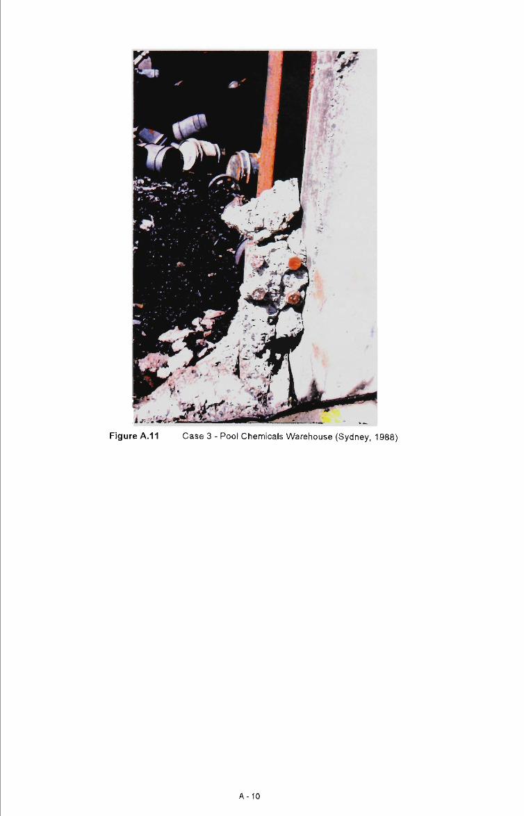
Figure A.11 Case 3 - Pool Chemicals Warehouse (Sydney, 1988)
A-10

Case 4 TOY FACTORY AND WAREHOUSE
(Melbourne 1989)
NOTE: Although this building is not a typical portal frame stnicture comprising of precast/m-up
concrete panels used as cladding It is seen as an important example showing the behaviour of such
buildings in fire.
Construction - The factory/warehouse construction consisted of steel portal ft-ames with fire
protected columns with masonry walls and an unprotected roof. The masonry walls were supported
by the portal frames. The building housed some ofllces at the front of the factory/warehouse
construction.
Fire Load - The fire load was very high consisting of timber, glue, cardboard and packaging.
The fire was very severe and burnt for more than six hours.
Fire Initiation and Spread - An adjacent building was located about 6m away but no fire spread
occurred.
Building Behaviour - Movement of the steel frames and explosions within the building resulted in
the early collapse of the brick wall along one side of the building. The brick encasements around
the portal frame columns also became dislodged. The rafters deformed downwards until they were
in contact with the floor with the columns being pulled inwards.
A-11

Figure A.12 Case 4 - Toy Factory and Warehouse (Melbourne, 1989)
Figure A.13 Case 4 - Toy Factory and Warehouse (Melbourne, 1989)
A-12
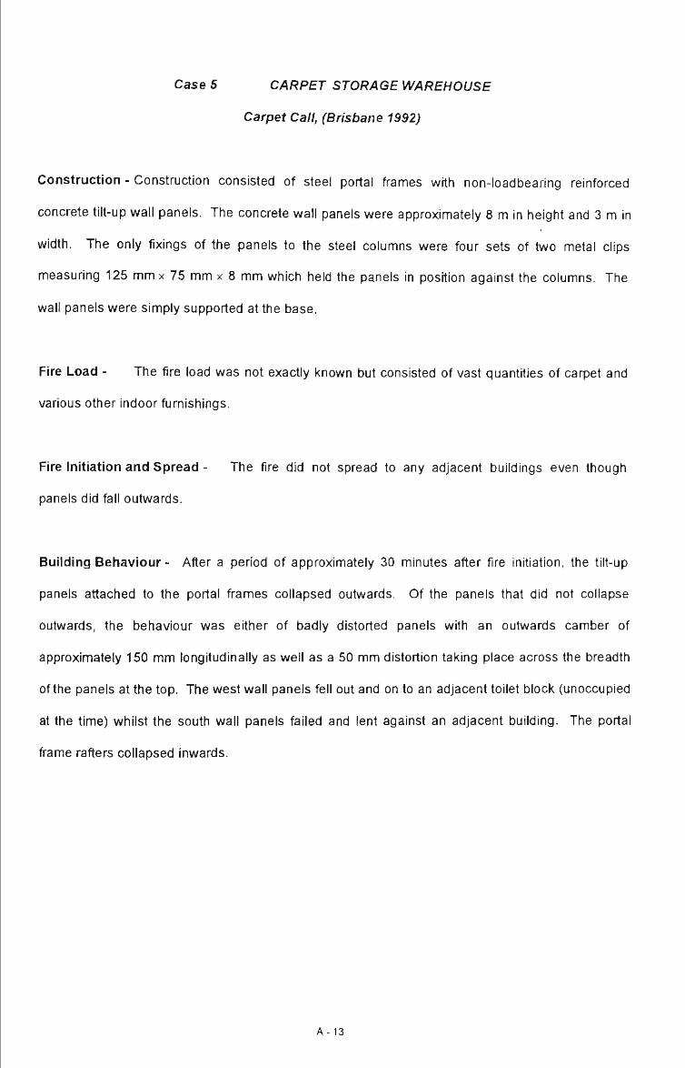
Case 5 CARPET STORAGE WAREHOUSE
Carpet Call, (Brisbane 1992)
Construction - Construction consisted of steel portal frames with non-loadbearing reinforced
concrete tilt-up wall panels. The concrete wall panels were approximately 8 m in height and 3 m in
width. The only fixings of the panels to the steel columns were four sets of two metal clips
measuring 125 mmx 75 mm x 8 mm which held the panels in position against the columns. The
wall panels were simply supported at the base.
Fire Load - The fire load was not exactiy known but consisted of vast quantities of carpet and
various other indoor furnishings.
Fire Initiation and Spread - The fire did not spread to any adjacent buildings even though
panels did fall outwards.
Building Behaviour- After a period of approximately 30 minutes after fire initiation, the tilt-up
panels attached to the portal frames collapsed outwards. Of the panels that did not collapse
outwards, the behaviour was either of badly distorted panels with an outwards camber of
approximately 150 mm longitudinally as well as a 50 mm distortion taking place across the breadth
of the panels at the top. The west wall panels fell out and on to an adjacent toilet block (unoccupied
at the time) whilst the south wall panels failed and lent against an adjacent building. The portal
frame rafters collapsed inwards.
A - 1 3
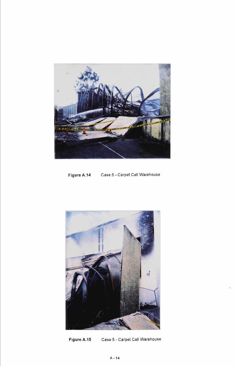
Figure A.14 Case 5 - Carpet Call Warehouse
Figure A.15 Case 5 - Carpet Call Warehouse
A-14

Figure A.16 Case 5 - Carpet Call Warehouse
Figure A.17 Case 5 - Carpet Call Warehouse
A-15
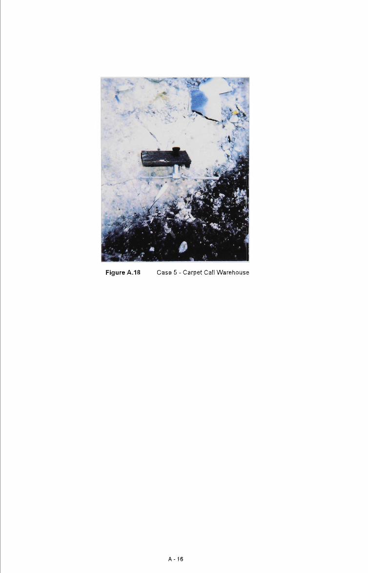
Figure A.18 Case 5 - Carpet Call Warehouse
A-16

B3.0 Thermal Properties
In addition to the stress-strain relationships it is also necessary to take account of the thermal
expansion of both concrete and reinforcing steel. Models as given in Eurocode 4 are
described below.
B3.1 Steel
The values of thermal elongation for all structural and reinforcing steels over varying
temperatures is given by the following:
f ) = -2 .416x10 - ' ' - ^2x10 - ^ (e3 )+0 .4x10 - ^ (e3 ) ' for 20°C<e3 <750°C
= 11x10"^
= - 6 . 2 x 1 0 " ^ + 2 x10-^ (e3)
for 750° C < e . <860°C
for 860°C<e3 <1200°C
where:
's
(Al)s
es
length at room temperature, (m)
temperature included elongation, (m)
steel temperature, (°C)
B3.2 Concrete
The values of thermal elongation for concrete over varying temperatures is given by the
following:
- 1 . 8 x 1 0 - ^ + 9 x 1 0 - ^ ( e J + 2 . 3 x 1 0 - ' ^ ( G J ' for 20°C < e , <700°C
= 14x10" for 700°C<e„ <1200°C
B-3
where:
Ic = length at room temperature, (m)
(Al)c = temperature induced elongation, (m)
©c = concrete temperature, (°C)
B-4

1.00 1
Elastic Modulus vs Steel Temperature
Steel Temperature, (Deg. C)
Figure 8.1 : Elastic Modulus versus Temperature - (Steel)
1.00 -
(§ ::T 0.90 -to 17 0.80 -S> 15 is c n 70 -
Pro
po
rtio
nal
Lim
it S
P
erce
nta
ge
of O
rigi
3
p
p
O
O
O
O
3 ^
Ko
CO
j^
cn
b)
D
o
o
o
o
o
o
c c\
Proportional Stress vs Steel Temperature
o o o o o o o o o o o c o o o o o o o o o o o c t - c M c o ' ^ m c D r ^ o o a ) O T - c N
Steel Temperature, (Deg. C)
1
Figure 8.2: Proportional Limit Stress versus Temperature - (Steel)
B-5

in vp
"53 • = > 2
_ J
M M k. +.» (0
3
l-X (0 s
D> k.
O <»-0 0)
tag
c 0) u ^ 0)
a.
o CM
Maximum Stress vs Steel Temperature
0 90 -0 80 -0 70 -0 60 0 50 0 40 -0 30 -0 20 -0.10 -nnn .
[
\
o o
o o CM
O O CO
o o o o LO
o o CD
O
o o o 00
o o C3)
o o o o o
o o CM
steel Temperature, (Deg. C)
Figure 8.3: Maximum Stress Level versus Temperature - (Steel)
Concrete Compressive Strain vs Temperature
Temperature, (Deg. C)
Figure 8.4: Compressive Strain versus Temperature - (Concrete)
B-6

O g) «»- ^^ O (0
g'.s c w II a> c Q- o
O
o Cvl
Concrete Compressive Strength vs Temperature
0 90 -0 80 -0 70 -0 60 0 50 -0 40 . 0 30 0 20 -0 10 -nnn
o o o
o CM
o o CO
o o
o o LO
o o CD
o o
o o 00
o o en
o o o
o o
o o CM
Temperature, (Deg. C)
Figure 8.5: Compressive Strength versus Temperature - (Concrete)
B - 7

APPENDIX C WALL MODEL PROGRAM LISTING
C1.0 Introduction
Provided in this Appendix is the entire program listing of the wall model described in Chapter 3.
The program listing was written in Q-Basic format
C2.0 Wall Model Program Listing
REM " " " " " " " " " " « " " WALL MODEL PROGRAM LISTING " " " " " • • • • " REM " " " " * " DEVELOPED FOR MASTERS STUDY INTO BEHAVIOUR OF " " • " * " " REM " " " CANTILEVERED CONCRETE WALLS AT ELEVATED TEMPERATURES REM " " " " " " " " " " DATE OF LAST EDIT - 2 SEPTEMBER 1994 " • " . " " " • "
DEFDBLA-Z DIM LATMOM(26), SWM(26), D(26), DELTA(30), CONCSTR(IO), FC(10), EC(10), T(10), CURV(26), PPSI(26), THETA(26), DISP(26), LENGTH(9), DIST(10), ALPHAC(10), ALPHAS{10), THSTRAINC(IO), THSTRAINS(IO), EM{10), ETOTI(IO), ETOT2(10), ETOT3(10), STSTRAINI(IO), STSTRAIN2(10), STSTRAIN3(10), FORCEI(IO), FORCE2(10), FORCE3(10), MOM1(10), MOM2(10), MOM3{10), ET(10), STMOD(10), PRSTRESS(IO), MSTRESS(IO), PRSTRAIN(IO), AVDELTA(26) CLS
REM * * " * " * " " USER INPUT " * " " " * " INPUT "IS THIS THE START OF A NEW ANALYSIS"; RUN$ INPUT 'WHAT IS THE FIRE EXPOSURE - 2.5, 5, 7.5, 10, 15, 20, 25, 30, 60, OR 90 MIN"; ISO INPUT 'WHAT IS THE REINFORCEMENT RATIO"; PW INPUT 'WHAT IS THE WALL HEIGHT - 6m or 8m"; H INPUT "HOW MANY ELEMENTS UP THE WALL"; G INPUT 'WHAT ELEMENT HAS THE STEEL REINFORCEMENTIE. X"; X INPUT "DO YOU WANT SELF WEIGHT EFFECTS - (Y/N)"; SW$ INPUT'WHAT IS THE AXIAL FORCE - EG. OkN, 5kN, lOkN"; N INPUT 'WHAT IS THE LATERAL LOAD - OEG. kN, 0.25kN, O.SkN, 0.75kN, 1 .OkN"; P INPUT "HOW MANY OF THE ABOVE ELEMENTS DOES THE ISO FIRE ACT'; K
CLS
COUNTER = 0 W=1 L = (H/G)*1000 AREA = 15*L 56 IF SW$ = 'Y" OR SW$ = "V" THEN 57 ELSE 60 57SW=.15*W*(L/1000)*25 60 AST =PW*.15*1 * 1000000 EO = 200000 FAY = 400 FCO = 32 PPSI(1) = 0 DISP(O) = 0 THETA(O) = 0 SWMTOT = 0
C-1

REM " * " " • " " READ TEMPERATURE DISTRIBUTIONS * " " " " " FOR 1 = 1 TO 10
READ IS02.5A(I) NEXT I FOR 1 = 1 TO 10
READ IS02.5B(I) NEXT I F0RI = 1TO 10
READ IS05A(I) NEXT I F0RI = 1TO 10
READ IS05B(I) NEXT I F0RI = 1TO 10
READ IS07.5A(I) NEXT I F0RI = 1TO 10
READ IS07.5B(I) NEXT I F0RI = 1TO 10
READISOIOA(I) NEXT I FOR 1 = 1 TO 10
READISOIOB(I) NEXT I FOR 1 = 1 TO 10
READIS015A(I) NEXT I FOR 1 = 1 TO 10
READIS015B(I) NEXT I FOR 1 = 1 TO 10
READ ISO20A(l) NEXT! F0RI = 1TO 10
READ ISO20B(l) NEXT I FOR 1 = 1 TO 10
READ IS025A(I) NEXT I FOR I = 1 TO 10
READ IS025B(I) NEXT I FOR 1 = 1 TO 10
READ ISO30A(l) NEXT I FOR 1 = 1 TO 10
READ ISO30B(l) NEXT I F0RI = 1TO 10
READ ISO60A(l) NEXT I FOR 1=1 TO 10
READ ISO60B(l) NEXT I F0RI = 1TO 10
READ ISO90A(l) NEXT I FOR 1 = 1 TO 10
READ ISO90B{l) NEXT I
REM " " " " " " READ CENTROID DISTANCES " " * — * " F0RI = 1TO 10 READ DIST(I) NEXT I
REM " " " " " " READ DEFORMED SHAPE • " " " " " * 90 IF RUN$ = 'YES" OR RUN$ = "yes" THEN 91 ELSE 92
C-2

91 OPEN "B:\DELTA1 .DAT' FOR INPUT AS #1 FOR J = 1 TO G + 1 INPUT #1,DELTA(J) IF E0F(1) THEN CLOSE NEXT J CLOSE #1
GOTO 93
92 OPEN "B:\DELTA.DAT" FOR INPUT AS #2 FOR J = 1 TO G + 1 INPUT#2, DELTA(J) IF E0F(2) THEN CLOSE NEXT J CLOSE #2
93 REM " " " " " " CALCULATE LATERAL M O M E N T " " " " " " FOR J = 1 TO G LATMOM(J) = P*(J*L/1000) NEXT J
REM " " " " " " INITIATE T1 AND T2 ZONES * " " " " " * 94 IF ISO = 2.5 THEN 95 ELSE 100 95 FORI = 1TO10 96 LET T1 (I) = IS02.5A(I) 97 LETT2(I) = IS02.5B(I) 98 NEXT I 99 GOTO 510 100 IF ISO = 5 THEN 110 ELSE 151 110 FORI = 1TO10 120 LETT1(I) = IS05A(I) 130 LETT2(I)=IS05B(I) 140 NEXT I 150 GOTO 510 151 IF ISO = 7.5 THEN 152 ELSE 160 152 FORI = 1TO10 153 LETT1(I) = IS07.5A(I) 154 LETT2(I)=IS07.5B(I) 155 NEXT I 156 GOTO 510 160 IF ISO = 10 THEN 170 ELSE 220 170 FORI = 1TO10 180 LETT1(l)=ISO10A(l) 190 LETT2(l) = ISO10B(l) 200 NEXT I 210 GOTO 510 220 IF ISO = 15 THEN 230 ELSE 280 230 FORI = 1TO10 240 LETT1(I) = IS015A(I) 250 LETT2(I) = IS015B(I) 260 NEXT I 270 GOTO 510 280 IF ISO = 20 THEN 290 ELSE 340 290 FORI = 1TO10 300 LETT1(l) = ISO20A(l) 310 LET T2(l) = ISO20B(l) 320 NEXT I 330 GOTO 510 340 IF ISO = 25 THEN 350 ELSE 400 350 FOR 1 = 1 TO 10 360 LETT1(I) = IS025A{I) 370 LET T2(l) = IS025B(I) 380 NEXT I 390 GOTO 510 400 IF ISO = 30 THEN 410 ELSE 455 410 FOR 1 = 1 TO 10 420 LETT1(l) = ISO30A(l) 430 LET T2(l) = ISO30B(l) 440 NEXT I 450 GOTO 510 455 IF ISO = 60 THEN 460 ELSE 485
C-3

460 FORI = 1TO10 465 LETT1(l) = ISO60A(l) 470 LET T2(l) = ISO60B(l) 475 NEXT I 480 GOTO 510 485 IF ISO = 90 THEN 490 ELSE 506 490 FORI = 1TO10 495 LETT1(l) = ISO90A(l) 500 LETT2(l) = ISO90B(l) 504 NEXT I 505 GOTO 510 506 PRINT 'YOU HAVE CHOSEN A WRONG FIRE EXPOSURE TIME"
507 END
510
REM " " " " " " CALCULATION OF P-DELTA EFFECTS * " " " • " " FOR J = 1 TO G AVDELTA(J) = (DELTA(G + 2 - J) + DELTA(G + 1 - J)) / 2 D{J) = 1000 - 75 + AVDELTA(J) SWM(J) = D(J)*SW/1000 NEXT J REM " " " " " " MAJOR LOOP - DISCRETISATION UP THE WALL * " " " " * • * 520 FOR J = 1 TO G
521 IF J <= KTHEN 525 ELSE 522
522 FORI = 1TO10 LETT1(I) = T2(I)
NEXT I
525 FORI = 1 TO 10 526 IF T1 (I) < 700 THEN 527 ELSE 529 527 ALPHAC(I) = ((-.00018) + (.000009 * T1 (I)) + (2.3E-11 * (T1 (I) - 3))) / T1 (I) 528 GOTO 530 529 ALPHAC(I) = .014/T1(I) 530 NEXT I
540 FORI = 1TO10 541 IF T1 (I) < 750 THEN 542 ELSE 544 542 ALPHAS(I) = ((-.0002416) + (.000012 * T1 (I)) + (4E-09 * (T1 (I) " 2))) / T1 (I) 543 GOTO 548 544 IF T1 (I) < 860 THEN 545 ELSE 547 545 ALPHAS(I) = .011/T1(l) 546 GOTO 548 547 ALPHAS(I) = ((-.0062) + (.00002 * T1 (I))) / T1 (I) 548 NEXT I
FOR I = 1 TO 10 FC(I) = (-.11122361# + (1.0663556# / (1 + ((T1 (I) / 604.16012#) * 3.4937958#)))) * 10 EC(1) = .0025046758# + (.012746344# / (1 + (EXP(-(T1 (I) - 448.18143#) /131.32673#)))) THSTRAINC(I) = ALPHAC(I) * (T1 (I) - 20) THSTRAINS(I) = ALPHAS(I) * (T1(l) - 20) STMOD(I) = (EXP(9.8979704# + (-.00000011447754* * (T1 (I) * 2) * (T1 (I) ' (1 / 2))))) * 10 PRSTRESS(I) = (EXP(3.2218205# + (-.0000047300503# * ((T1 (I)) * 2)))) * 10 MSTRESS(I) = (.37559807* + (24.839931 # / (1 + (T1 (I) / 589.44682#) * 7.6729164#))) * 10 PRSTRAIN(I) = PRSTRESS(I) / STMOD(I)
NEXT I
SWMTOT = SWMTOT + SWM(J) REMIFJ>1 THEN 1000
REM " " " " " " INITIALISATION FOR NEWTON-RAPHSON SOLVING METHOD " " * FOR AA = .5 TO 1.5 STEP .05 E01 =THSTRAINC(1)*AA FOR BB = .5 TO 1.5 STEP .05 COUNTER = 0 EI = THSTRAINC(10)*BB M1 =(EI-E01)/135
C-4
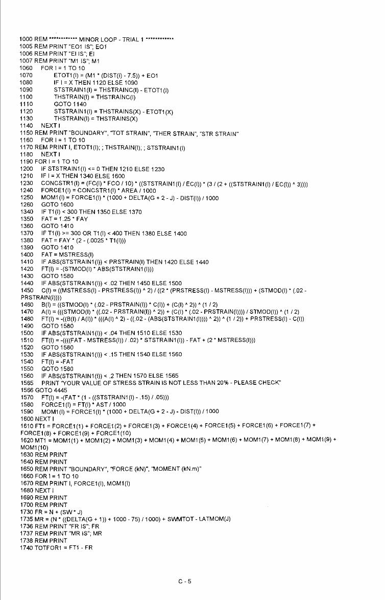
1000 REM " " " " " " MINOR LOOP -TRIAL 1 " * " " " " * 1005 REM PRINT "E01 IS"; E01 1006REMPRINT"EIIS";EI 1007 REM PRINT "Ml IS"; Ml 1060 FOR 1 = 1 TO 10 1070 ET0T1 (I) = (Ml * (DIST(I) - 7.5)) + E01 1080 IFI=XTHEN1120ELSE1090 1090 STSTRAINI(I) = THSTRAINC(I) - ETOTI(I) 1100 THSTRAIN(I) = THSTRAINC(I) 1110 GOT01140 1120 STSTRAIN1 (I) = THSTRAINSpC) - ET0T1 (X) 1130 THSTRAIN(I) = THSTRAINS(X) 1140 NEXTI 1150 REM PRINT "BOUNDARY", 'TOT STRAIN", 'THER STRAIN" "STR STRAIN" 1160 FORI = 1TO10 1170 REM PRINT I, ETOTI(I);; THSTRAIN(I);; STSTRAINI(I) 1180 NEXTI 1190FORI = 1 TO 10 1200 IF STSTRAINI(I) <= 0 THEN 1210 ELSE 1230 1210 IFI=XTHEN1340ELSE1600 1230 CONCSTRI(I) = (FC(I) * FCO /10) * ((STSTRAINI(I) / EC(I)) * (3 / (2 + ((STSTRAINI(I) / EC(I)) * 3)))) 1240 FORCE1(I) = CONCSTR1(I)*AREA/1000 1250 M0M1 (I) = F0RCE1 (I) * (1000 + DELTA(G + 2 - J) - DIST(I)) /1000 1260 GOT01600 1340 IF T1 (I) < 300 THEN 1350 ELSE 1370 1350 FAT =1.25* FAY 1360 GOT01410 1370 IF T1(l) >= 300 OR T1(l) < 400 THEN 1380 ELSE 1400 1380 FAT = FAY * (2 - (.0025 * T1 (I))) 1390 GOT01410 1400 FAT = MSTRESS(I) 1410 IF ABS(STSTRAIN1 (I)) <PRSTRAIN(I) THEN 1420 ELSE 1440 1420 FT(I) = -(STMOD(I) * ABS(STSTRAIN1 (I))) 1430 GOT01580 1440 IFABS(STSTRAIN1(I)) < .02 THEN 1450 ELSE 1500 1450 C(l) = ((MSTRESS(I) - PRSTRESS(I)) " 2) / ((2 * (PRSTRESS(I) - MSTRESS(I))) + (STMOD(I) * (.02 -PRSTRAIN(I)))) 1460 B(l) = ((STMOD(I) * (.02 - PRSTRAIN(I)) * C(l)) + (C(l) * 2)) * (1 / 2) 1470 A(l) = (((STMOD(I) * ((.02 - PRSTRAIN(I)) * 2)) + (C(l) * (.02 - PRSTRAIN(I)))) / STMOD(I)) * (1 / 2) 1480 FT(I) = -((B(l) / A(l)) * (((A(l) * 2) - ((.02 - (ABS(STSTRAIN1 (I)))) * 2)) -* (1 / 2)) + PRSTRESS(I) - C(l)) 1490 GOT01580 1500 IF ABS(STSTRAIN1(I))<.04 THEN 1510 ELSE 1530 1510 FT(I) = -((((FAT - MSTRESS(I)) / .02) * STSTRAINI(I)) - FAT + (2 * MSTRESS(I))) 1520 GOT01580 1530 IFABS(STSTRAIN1(I)) < .15 THEN 1540 ELSE 1560 1540 FT(I) = -FAT 1550 GOT01580 1560 IF ABS(STSTRAIN1(I)) < .2 THEN 1570 ELSE 1565 1565 PRINT 'YOUR VALUE OF STRESS STRAIN IS NOT LESS THAN 20% - PLEASE CHECK" 1566 GOTO 4445 1570 FT(I) = -(FAT * (1 - ((STSTRAIN1 (I) - .15)/ .05))) 1580 FORCE1(I) = FT(I)*AST/1000 1590 M0M1 (I) = FORCE1 (I) * (1000 + DELTA(G + 2 - J) - DIST(I)) /1000 1600 NEXT I 1610 FT1 = F0RCE1(1) + F0RCE1(2) + FORCE1(3) + F0RCE1(4) + F0RCE1(5) + F0RCE1(6) + F0RCE1(7) + F0RCE1 (8) + F0RCE1 (9) + F0RCE1 (10) 1620 MT1 = M0M1(1) + M0M1(2) + M0M1(3) + M0M1(4) + M0M1(5) + M0M1(6) + M0M1(7) + M0M1(8) + M0M1(9) + MOM1(10) 1630 REM PRINT 1640 REM PRINT 1650 REM PRINT "BOUNDARY", "FORCE (kN)", 'TVIOMENT (kN.m)" 1660FORl = 1TO10 1670 REM PRINT I, FORCEI(I), M0M1(I) 1680 NEXT I 1690 REM PRINT 1700 REM PRINT 1730FR = N + (SW*J) 1735 MR = (N * ((DELTA(G + 1)) + 1000 - 75) / 1000) + SWMTOT - LATMOM(J) 1736 REM PRINT "FR IS"; FR 1737 REM PRINT "MR IS"; MR 1738 REM PRINT 1740TOTFOR1 = FT1 - FR
C-5

1745 T0TM0M1 = MT1 - MR 1746 REM PRINT 'TOTAL FORCE ASSOCIATED WITH TRIAL 1 IS"; T0TF0R1 1747 REM PRINT 'TOTAL MOMENT ASSOCIATED WITH TRIAL 1 IS'- T0TM0M1 1748 REM PRINT 1749 REM PRINT "SWMTOT IS"; SWMTOT 1750 REM PRINT 1751 IF ABS(TOTFORI) > 1 THEN 2000 ELSE 1755 1755 IF ABS(T0TM0M1) > 1 THEN 2000 ELSE 4544
2000 REM " * " " " " * MINOR LOOP - TRIAL 2 * • * " " " " • 2010EO2 = EO1 2020 M2 = Ml + (M1 / 1000000) 2030 REM PRINT "E02 IS"; E02 2040 REM PRINT "El IS"; El 2050 REM PRINT "M2 IS"; M2 2060FORI = 1 TO 10 2070 ET0T2(I) = (M2 * (DIST(I) - 7.5)) + E02 2080 IF I = X THEN 2120 ELSE 2090 2090 STSTRAIN2(I) = THSTRAINC(I) - ET0T2(I) 2100 THSTRAIN(I) = THSTRAINC(I) 2110 GOTO 2140 2120 STSTRAIN2(I) = THSTRAINS(X) - ET0T2(X) 2130 THSTRAIN(I) = THSTRAINS(X) 2140 NEXTI 2150 REM PRINT "BOUNDARY", 'TOT STRAIN", 'THERM STRAIN", "STR STRAIN" 2160 FOR 1 = 1 TO 10 2170 REM PRINT I, ET0T2(I);; THSTRAIN(I);; STSTRAIN2(I) 2180 NEXTI 2190FORI = 1 TO 10 2200 IF STSTRAIN2(I) <= 0 THEN 2210 ELSE 2230 2210 IF I = X THEN 2340 ELSE 2600 2230 C0NCSTR2(I) = (FC(I) * FCO /10) * ((STSTRAIN2(I) / EC(I)) * (3 / (2 + ((STSTRAIN2(I) / EC(I)) * 3)))) 2240 F0RCE2(I) = CONCSTR2(l) * AREA /1000 2250 MOM2(l) = F0RCE2(I) * (1000 + DELTA(G + 2 - J) - DIST(I)) /1000 2260 GOTO 2600 2340 IF T1 (I) < 300 THEN 2350 ELSE 2370 2350 FAT = 1.25 * FAY 2360 GOTO 2410 2370 IF T1 (I) >= 300 OR T1 (I) < 400 THEN 2380 ELSE 2400 2380 FAT = FAY * (2 - (.0025 * T1 (I))) 2390 GOTO 2410 2400 FAT = MSTRESS(I) 2410 IF ABS(STSTRAIN2(I)) < PRSTRAIN(I) THEN 2420 ELSE 2440 2420 FT(I) = -(STMOD(I) * ABS(STSTRAIN2(I))) 2430 GOTO 2580 2440 IF ABS(STSTRAIN2(I)) < .02 THEN 2450 ELSE 2500 2450 C(l) = ((MSTRESS(I) - PRSTRESS(I)) - 2) / ((2 * (PRSTRESS(I) - MSTRESS(I))) + (STMOD(I) * (.02 -PRSTRAIN(I)))) 2460 B(l) = ((STMOD(I) * (.02 - PRSTRAIN(I)) * C(l)) + (C(l) * 2)) ^ 1 / 2) 2470 A(l) = (((STMOD(I) * ((.02 - PRSTRAIN(I)) * 2)) + (C(l) * (.02 - PRSTRAIN(I)))) / STMOD(I)) * (1 / 2) 2480 FT(I) = -((B(l) / A(l)) * (((A(l) " 2) - ((.02 - (ABS(STSTRAIN2(I))))'' 2)) '^ (1 / 2)) + PRSTRESS(I) - C(l)) 2490 GOTO 2580 2500 IF ABS(STSTRAIN2(I)) < .04 THEN 2510 ELSE 2530 2510 FT(I) = -((((FAT - MSTRESS(I)) / .02) * STSTRAIN2(I)) - FAT + (2 * MSTRESS(I))) 2520 GOTO 2580 2530 IF ABS(STSTRAIN2(I)) < .15 THEN 2540 ELSE 2560 2540 FT(I) = -FAT 2550 GOTO 2580 2560 IF ABS(STSTRAIN2(I)) < .2 THEN 2570 ELSE 2565 2565 PRINT 'YOUR VALUE OF STRESS STRAIN IS NOT LESS THAN 20% - PLEASE CHECK" 2566 GOTO 4445 2570 FT(I) = -(FAT * (1 - ((STSTRAIN2(I) -.15)/ .05))) 2580 FORCE2(l) = FT(I) * AST /1000 2590 M0M2(I) = F0RCE2(I) * (1000 + DELTA(G + 2 - J) - DIST(I)) /1000 2600 NEXT I 2610 FT2 = F0RCE2(1) + FORCE2(2) + FORCE2(3) + FORCE2(4) + FORCE2(5) + F0RCE2(6) + FORCE2(7) + FORCE2(8) + FORCE2(9) + FORCE2(10) 2620 MT2 = M0M2(1) + MOM2(2) + MOM2(3) + MOM2(4) + MOM2(5) + MOM2(6) + MOM2(7) + MOM2(8) + MOM2(9) + MOM2(10) 2630 REM PRINT 2640 REM PRINT
C-6

2650 REM PRINT "BOUNDARY", "FORCE (kN)", 'TVIOMENT (kN.m)" 2660 FOR 1 = 1 TO10 2670 REM PRINT I, FORCE2(l), MOM2(l) 2680 NEXT I 2690 REM PRINT 2700 REM PRINT 2725 T0TF0R2 = FT2 - FR 2730 T0TM0M2 = MT2 - MR 2735 REM PRINT 'TOTAL FORCE ASSOCIATED WITH TRIAL 2 IS"; T0TF0R2 2740 REM PRINT 'TOTAL MOMENT ASSOCIATED WITH TRIAL 2 IS"; T0TM0M2
3000 REM " " " " " " MINOR LOOP - TRIAL 3 * " " " * " " 3010 E03 = E01 + (E01 /1000000) 3020 M3 = Ml 3030 REM PRINT "E03 IS"; E03 3040 REM PRINT "El IS"; El 3050 REM PRINT "M3 IS IS"; M3 3060 FORI = 1TO10 3070 ETOT3(l) = (M3 * (DIST(I) - 7.5)) + E03 3080 IF I = X THEN 3120 ELSE 3090 3090 STSTRAIN3(I) = THSTRAINC(I) - ETOT3(l) 3100 THSTRAIN(I) = THSTRAINC(I) 3110 GOTO 3140 3120 STSTRAIN3(I) = THSTRAINS(X) - ET0T3(X) 3130 THSTRAIN(I) = THSTRAINS(X) 3140 NEXTI 3150 REM PRINT "BOUNDARY", 'TOT STRAIN", 'THER STRAIN"," STR STRAIN " 3160 FORI = 1TO10 3170 REM PRINT I, ETOT3(l);; THSTRAIN(I);; STSTRAIN3(I) 3180 NEXTI 3190 FOR 1=1 TO 10 3200 IF STSTRAIN3(I) <= 0 THEN 3210 ELSE 3230 3210 IF I =X THEN 3340 ELSE 3600 3230 C0NCSTR3(I) = (FC(I) * FCO /10) * ((STSTRAIN3(I) / EC(I)) * (3 / (2 + ((STSTRAIN3(I) / EC(I))'' 3)))) 3240 F0RCE3(I) = CONCSTR3(l) * AREA /1000 3250 M0M3(I) = FORCE3(l) * (1000 + DELTA(G + 2 - J) - DIST(I)) /1000 3260 GOTO 3600 3340 IF T1 (I) < 300 THEN 3350 ELSE 3370 3350 FAT = 1.25 * FAY 3360 GOTO 3410 3370 IF T1 (I) >= 300 OR T1 (I) < 400 THEN 3380 ELSE 3400 3380 FAT = FAY * (2 - (.0025 * T1 (I))) 3390 GOTO 3410 3400 FAT = MSTRESS(I) 3410 IF ABS(STSTRAIN3(I)) < PRSTRAIN(I) THEN 3420 ELSE 3440 3420 FT(I) = -(STMOD(I) * ABS(STSTRAIN3(I))) 3430 GOTO 3580 3440 IF ABS(STSTRAIN3(I)) < .02 THEN 3450 ELSE 3500 3450 C(l) = ((MSTRESS(I) - PRSTRESS(I)) * 2) / ((2 * (PRSTRESS(I) - MSTRESS(I))) + (STMOD(I) * (.02 -PRSTRAIN(I)))) 3460 8(1) = ((STMOD(I) * (.02 - PRSTRAIN(I)) * C(l)) + (0(1) * 2)) - (1 / 2) 3470 A(l) = (((STMOD(I) * ((.02 - PRSTRAIN(I)) * 2)) + (C(l) * (.02 - PRSTRAIN(I)))) / STMOD(I)) * (1 / 2) 3480 FT(I) = -((B(l) / A(l)) * (((A(l) " 2) - ((.02 - (ABS(STSTRAIN3(I)))) * 2)) * (1 / 2)) + PRSTRESS(I) - C(l)) 3490 GOTO 3580 3500 IF ABS(STSTRAIN3(I)) < .04 THEN 3510 ELSE 3530 3510 FT(I) = -((((FAT - MSTRESS(I)) / .02) * STSTRAIN3(I)) - FAT + (2 * MSTRESS(I))) 3520 GOTO 3580 3530 IF ABS(STSTRAIN3(I)) < .15 THEN 3540 ELSE 3560 3540 FT(I) = -FAT 3550 GOTO 3580 3560 IF ABS(STSTRAIN3(I)) < .2 THEN 3570 ELSE 3565 3565 PRINT 'YOUR VALUE OF STRESS STRAIN IS NOT LESS THAN 20% - PLEASE CHECK' 3566 GOTO 4445 3570 FT(I) = -(FAT * (1 - ((STSTRA1N3(I) - .15)/ .05))) 3580 F0RCE3(I) = FT(I) * AST /1000 3590 M0M3(I) = FORCE3(l) * (1000 + DELTA(G + 2 - J) - DIST(I)) /1000 3600 NEXT I 3610 FT3 = F0RCE3(1) + FORCE3(2) + FORCE3(3) + FORCE3(4) + F0RCE3(5) + FORCE3(6) + F0RCE3(7) + FORCE3(8) + FORCE3(9) + FORCE3(10) 3620 MT3 = M0M3(1) + MOM3(2) + MOM3(3) + MOM3(4) + MOM3(5) + MOM3(6) + MOM3(7) + MOM3(8) + MOM3(9) + MOM3(10)
C-7

3630 REM PRINT 3640 REM PRINT 3650 REM PRINT "BOUNDARY", "FORCE (kN)", "MOMENT (kN.m)" 3660FORI = 1 TO 10 3670 REM PRINT I, F0RCE3(I), M0M3(I) 3680 NEXT I 3690 REM PRINT 3700 REM PRINT 3725 T0TF0R3 = FT3 - FR 3730 T0TM0M3 = MT3 - MR 3735 REM PRINT 'TOTAL FORCE ASSOCIATED WITH TRIAL 3 IS"; T0TF0R3 3740 REM PRINT 'TOTAL MOMENT ASSOCIATED WITH TRIAL 3 IS"; T0TM0M3
4000 REM " " " " " " NEWTON-RAPHSON METHOD FOR SOLVING A TWO DIMENSIONAL ARRAY " 4011 DFDE = (FT3 - FT1) / (E01 /1000000) 4020 DFDC = (FT2 - FT1) / (M1 /1000000) 4030 DMDE = (MT3 - MT1) / (E01 /1000000) 4040 DMDC = (MT2 - MT1) / (Ml /1000000) 4050 DET = (DFDE * DMDC) - (DFDC * DMDE) 4060 REM PRINT 'THE VALUE OF THE DETERMINANT IS"; DET 4070 REM PRINT 4080 REM PRINT "FT1 IS"; FT1 4090 REM PRINT "FT2 IS"; FT2 4100 REM PRINT "FT3 IS"; FTS 4110 REM PRINT "MT1 IS"; MT1 4120 REM PRINT "MT2 IS"; MT2 4130 REM PRINT "MT3 IS"; MT3 4140 REM PRINT 4150 REM PRINT "DFDE IS"; DFDE 4160 REM PRINT "DFDC IS"; DFDC 4170 REM PRINT "DMDE IS"; DMDE 4180 REM PRINT "DMDC IS"; DMDC 4190 REM PRINT 4200 REM PRINT "EXT. STRAIN", "CURVATURE", "FORCE", 'T^OMENT' 4210 REM PRINT
4221 IF Ml < 0 THEN GOTO 4222 ELSE 4250 4222 PRINT "Ml IS LESS THAN ZERO" 4223 GOTO 4445 4250 E01 NEW = E01 + (((-DMDC * T0TF0R1) + (DFDC * TOTMOM1)) / DET) 4260 PHINEW = Ml + (((DMDE * T0TF0R1) - (DFDE * T0TM0M1)) / DET)
4360 E01 =E01NEW 4370 Ml = PHINEW 4380 FT1 = 0 4381 FT2 = 0 4382 FT3 = 0 4383 MT1 = 0 4384 MT2 = 0 4385 MT3 = 0 4400FORI = 1 TO 10 4401 FORCE1(I) = 0 4402 F0RCE2(I) = 0 4403 F0RCE3(I) = 0 4404 M0M1 (I) = 0 4405 M0M2(1) = 0 4406 M0M3(I) = 0 4425 NEXT I
4430 COUNTER = COUNTER + 1 REM PRINT "COUNTER IS"; COUNTER 4440 IF COUNTER > 50 THEN 4450 ELSE 4490 4445 E01 = THSTRAINC(1) * AA 4450 NEXT BB 4460 N EXT AA 4480 PRINT 'THERE IS NO SOLUTION FOR THIS RANGE" 4485 END
4490 GOTO 1005
4544 CURV(J) = Ml
C-8

4545 PPSI(J) = CURV(J) * L
PRINT "FOUND SOLUTION FOR BOUNDARY"; J
4548 NEXT J
REM * " " " " " * CALCULATION OF DEFORMED SHAPE " " " " " CLS 4554 FOR J = 1 TO G + 1 4556 PPS1(1) = 0 4557 THETA(J) = THETA(J - 1) - PPSI(J) 4558 DISP(J) = INT(DISP(J -1) + (L * THETA(J -1)) - (PPSI(J) * L / 2)) 4559 PRINT "DISPLACEMENT AT BOUNDARY"; J; " IS";"" ; , -DISP(J) 4560 LET DELTA(J) = -DISP(J) 4570 NEXT J 4575 PRINT
OPEN "B:\DELTA.DAT' FOR OUTPUT AS #3 FOR J = 1 TO G + 1 WRITE #3, DELTA(J) NEXT J CLOSE #3
REM ****" DATA LINES CONTAINING ISO FIRE EXPOSURES, CENTROID DISTANCES AND DEFORMED SHAPE' REM * " * " 2.5 MIN ISO FIRE — * * DATA 25,25,25,25,25,25,25,25,26,90 DATA 25,25,25,25,25,25,25,25,25,25
: ****** REM ****" 5 MIN ISO FIRE ' DATA 25,25,25,25,25,25,25,27,57,178 DATA 25,25,25,25,25,25,25,25,25,25
REM * " * " 7.5 MIN ISO FIRE ****" DATA 25,25,25,25,25,25,26,42,82,249 DATA 25,25,25,25,25,25,25,25,25,25
REM ****" 10 MIN ISO FIRE ****" DATA 25,25,25,25,25,26,35,54,125,324 DATA 25,25,25,25,25,25,25,25,25,25
REM ****" 15 MIN ISO FIRE ****** DATA 25,25,25,25,28,33,52,88,196,441 DATA 25,25,25,25,25,25,25,25,25,25
REM * " * " 20 MIN ISO FIRE ***"* DATA 25,25,26,28,34,45,71.138,267,506 DATA 25,25,25,25,25,25,25,25,25,25
REM ****" 25 MIN ISO FIRE ***"* DATA 26,27,28,32,42,59,90,169,320,566 DATA 25,25,25,25,25,25,25,25,25,25
REM *"*** 30 MIN ISO FIRE ****** DATA 27,28,31,38,50,72,120,209,361,610 DATA 25,25,25,25,25,25,25,25,25,25
REM *"*** 60 MIN ISO FIRE " " * * DATA 47,53,64,82,116,172,254,372,535,766 DATA 25,25,25,25,25,25,25,25,25,25
REM ****" 90 MIN ISO FIRE ****" DATA 85,91,104,137,191,259,351,472,633,850 DATA 25,25,25,25,25,25,25,25,25,25
REM ****** CENTROID DISTANCES * * " " DATA 7.5, 22.5, 37.5, 52.5, 67.5, 82.5, 97.5, 112.5,127.5, 142.5
9999 END
C-9
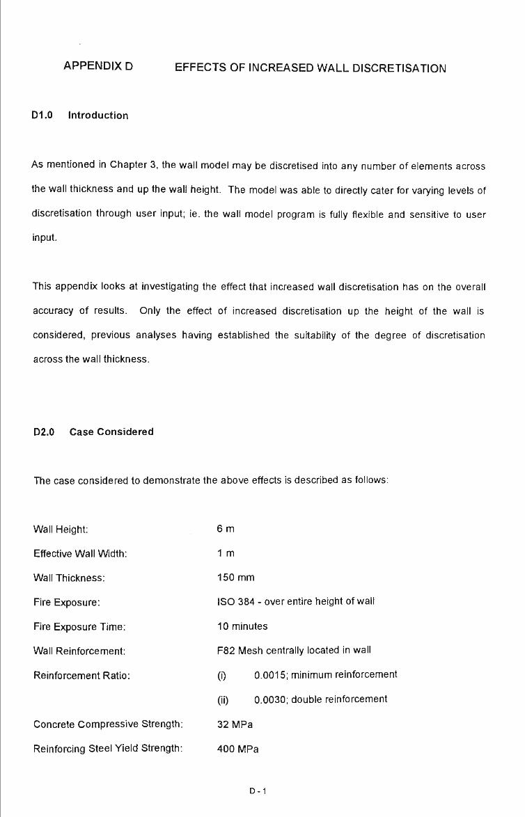
APPENDIX D EFFECTS OF INCREASED WALL DISCRETISATION
D1.0 Introduction
As mentioned in Chapter 3, the wall model may be discretised into any number of elements across
the wall thickness and up the wall height. The model was able to directly cater for varying levels of
discretisation through user input; ie. the wall model program is fully flexible and sensitive to user
input.
This appendix looks at investigating the effect that increased wall discretisation has on the overall
accuracy of results. Only the effect of increased discretisation up the height of the wall is
considered, previous analyses having established the suitability of the degree of discretisation
across the wall thickness.
D2.0 Case Considered
The case considered to demonstrate the above effects is described as follows:
Wall Height:
Effective Wall Width:
Wall Thickness:
Fire Exposure:
Fire Exposure Time:
Wall Reinforcement:
Reinforcement Ratio:
Concrete Compressive Strength:
Reinforcing Steel Yield Strength:
6 m
1 m
150 mm
ISO 384 - over entire height of wall
10 minutes
F82 Mesh centrally located in wall
(i) 0.0015; minimum reinforcement
(ii) 0.0030; double reinforcement
32 MPa
400 MPa
D-1

Two reinforcement situations are considered - the minimum reinforcement in a single layer, and
twice the minimum arranged in two layers. The reinforcement ratio of 0.0015 translates to
approximately 225 mm2/m of F82 mesh whilst the ratio of 0.0030 is approximately 450 mm2/m.
The above estimate of minimum reinforcement is consistent with that of cun-ent designs and
complies with AS 3600 (1988) - Section 11.
D3.0 Method of Analysis
The above wall examples were arbitrarily divided into 2, 5, 15, 20 and 25 elements. This spread of
elements was seen to give a reasonable indication of the effects that increased discretisation has
on the magnitude of displaced shape, and therefore of the calculated fire-resistance.
For the purpose of this study the fire exposure was assumed to act over the entire wall height thus
subjecting each of the elements up the wall height to identical thermal gradients.
This study considered the effects of fire only, with no lateral or axial loads being included, with the
exception of soft weight.
D-2

D4.0 Results of Analysis
The results of the above analysis are summarised in Table D.I below.
Table D.I Maximum Deflection of 6 m Wall with Varying Levels of Discretisation
MAXIMUM DEFLECTION AT TOP OF 6 m WALL, ( mm )
Reinforcement
Ratio,
Pw
0.0015
0.0030
Level of Discretisation
Number of Elements Up Length of Wall
2
326
323
5
420
409
15
439
406
20
438
405
25
439
399
It can be seen from the above results that the number of elements chosen will effect the accuracy of
the results. However, even five elements gives reasonable accuracy and beyond fifteen there is no
gain in accuracy. The conclusion is true for both reinforcement cases.
This conclusion is true for both reinforcement cases.
D-3

APPENDIX E CONNECTION MATERIAL PROPERTY TESTS
E1.0 Introduction
As previously mentioned, the steel components and concrete associated with the tested
connections were individually tested and recorded. This Appendix presents the results of these
tests.
E2.0 Concrete Component Tests
At the time the slabs were poured, five cylinders were cast to determine the compressive strength
and stress-strain relationships for the concrete.
Below is a summary of the compressive strength tests.
Table E.I Concrete Compressive Test Results - Pretest Data
Concrete Property
Expected Concrete Strength; (MPa)
Actual Concrete Strength; (MPa)
Ultimate Concrete Load; (kN)
Density; (kg/m^)
Cylinder Height; (mm)
Cylinder Diameter 1; (mm)
Cylinder Diameter 2; (mm)
Cylinder Weight; (kg)
Age at Time of Test
21 Days
.
48.5
855
2426
299
150.4
149.2
12.783
28 Days
32
45.8
805
2447
299
150.2
150.0
12.947
35 Days
-
49.4
872
2415
299
150.1
149.7
12.745
Two tests were conducted on the concrete cylinders in accordance with AS1012, Part 17 - 1976 to
obtain 'typical' stress-strain relationships. The setup is shown below in Figure E.1.
E-1
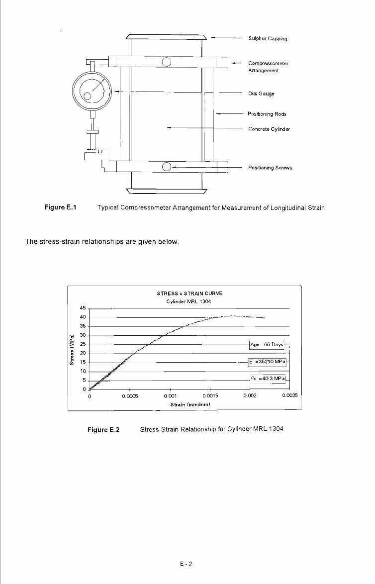
o
o-
iv — Sulphur Capping
Compressometer Arrangement
Dial Gauge
Positioning Rods
Concrete Cylinder
Positioning Screws
Figure E.I Typical Compressometer Anangement for Measurement of Longitudinal Strain
The stress-strain relationships are given below.
45 ,
40 -
35 .
« 3 0 . Q. S 25 .
8 20 . II
« 15
10.
5
0 (
STRESS V STRAIN CURVE
Cylinder MRL 1304
. """
^^ X -
) 0.0005 0.001 0.0015
Strain Imm/mm)
Age 66 Days —
E =35210 MPa-
f c =40.3 MPa
0.002 0.0 025
Figure E.2 Stress-Strain Relationship for Cylinder MRL 1304
E-2

50 ,
45 -
40-
_ 35 « 1 30 ". 25 • 20 .
^ 15 .
10-
5 -
0 -
STRESS V STRAIN CURVE
MRL Cylinder 1307
^^,-'-'^ ~ ^„- '-^ '
^^"^ __^
^
j ^ ^ ^
- / ^ j ^
D 0.0005 0.001 0.0015
Strain (mm/mm)
Age 66 days —
E =36,347 MPa
fc -40.3 MPa
0.002 0.0025
Figure E.3 Stress-Strain Relationship for Cylinder MRL 1307
E3.0 Steel Component Tests
To determine the Modulus of Elasticity of the steel plate used in the connection tests, a number of
room temperature tensile tests had to be undertaken. In all, three coupons were cut from the same
specimen of steel used for the connection tests. The dimensions of the steel coupon are given in
Figure E4 below.
190 mm APPROX.
40 mm MIN.
75 mm *l-
1.0 mm
40 mm MIN.
25.4 mm + 0 mm 1
-0.1 mm ' FOR INSTRON MACHINE
A • R 25 mm MIN
12.5 mm *l- 0.03 mm
R 25 mm MIN.
25.4 mm * ° ' " ™ \ FOR INSTRON -0.1 mm '
MACHINE
Figure E.4 Standard B-34 Tensile Coupon Test Specimen
E-3
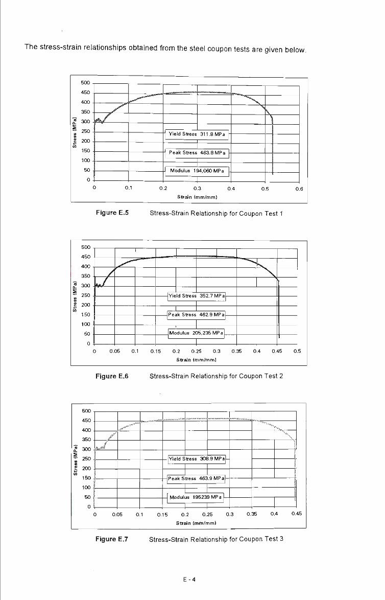
The stress-strain relationships obtained from the steel coupon tests are given below.
0.2 0.3 0.4
Strain (mm/mm)
0.5 0.6
Figure E.5 Stress-Strain Relationship for Coupon Test 1
500
450
400
350
,? 300 -a.
I 250
in 200
160
100
50
Yield stress 352.7 IVIP a
Pealc stress 462.9 IVIP a
Modulus 205.235 MPa
1 1 1 0 0.05 0.1 0.15 0.2 0.25 0.3 0.35 0.4 0.45 0.5
Sirdn (mm/mm)
Figure E.6 Stress-Strain Relationship for Coupon Test 2
R m
(MP
a)
H
£ 200 -<0
150 ,
100 1
50 ^
0 ^
(
^..^•'•"'
'
^ , . . > . ^ - - " ' ' - " ...-V-.---'-- ............................. ..-.....-.•.......•.•.•...•.-
Yield stress 308.9 MPa
Pealc Stress 463.9 MPa
Modulus 195239 MPa
1 1
™... . . . . . . . . . . .
••'••'.
I \ > i i
I
) 0.05 0.1 0.15 0.2 0.25 0.3 0.35 0.4 0.
Strain (mm/mm)
45
Figure E.7 Stress-Strain Relationship for Coupon Test 3
E-4

APPENDIX F DETERMINATION OF APPROXIMATE CLIP PLATE CAPACITIES
F1.0 Introduction
As previously mentioned, determination of the clip plate capacities is important for comparison with
the results obtained from the experimental tests as reported in Section 5.6.
The strength of two types of clip plate connection, as shown in Figure 5.3, are determined in this
Appendix.
F2.0 Calculation of Clip Plate Strength
F2.1 Non-Welded Clip Plate P 1
40 60 50
bolt clip plate
ferrule
OL
ELEVATION
UN-WELDED CLIP CONNECTION
Figure F.I Un-Welded Clip Plate Connection
(A ) Clip Plate Capacity
Equating the extemal forces with the intemal forces experienced by the connection the following is
obtained:
F-1

Internal Moment:
External Moment:
M ^ = — f,
M e = ^ l a
Eq.F1
Eq.F2
where:
Mi = internal moment
Me = external moment
b = clip plate width
d = clip plate thickness
fy = steel yield strength
P = ultimate applied connection load
la = lever arm between bolt and flange edge
Equating the above equations and solving for P:
bd^-f p _ '^^ 'y
P =
21a 100x10^-280
2x60
P = 23.3 kN
Eq. F3
The total load able to be carried by each connection is 23.3 kN
( B ) Bolt Capacity
The design bolt capacity can be determined from the AISC - Design Capacity Tables for Structural
Steel, (1st Edition -1991). From Table 7.1.3 (b) of the Design Capacity Tables;
Design Capacity for Ml6 High Strength bolt in Axial Tension is 104 kN
Clearly for the clip plate to act as a cantilever in bending, some prying effects must be present
(Figure F.2).
F-2
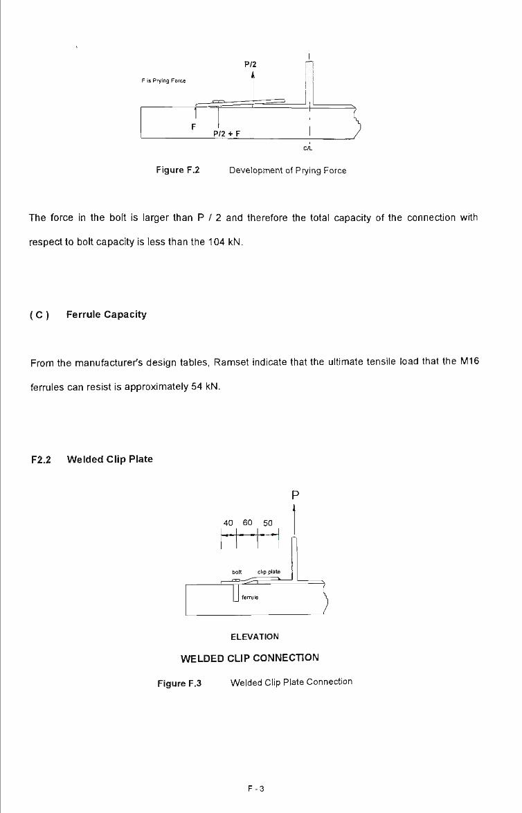
F is Prying Force
C/L
Figure F.2 Development of Prying Force
The force in the bolt is larger than P / 2 and therefore the total capacity of the connection with
respect to bolt capacity is less than the 104 kN.
(C ) Ferrule Capacity
From the manufacturer's design tables, Ramset indicate that the ultimate tensile load that the M16
ferrules can resist is approximately 54 kN.
F2.2 Welded Clip Plate
P
40 60 50
bolt clip plate
3 1
ELEVATION
WELDED CLIP CONNECTION
Figure F.3 Welded Clip Plate Connection
F-3

(A ) Clip Plate Capacity
Equating the external forces with the intemal forces experienced by the connection we obtain the
following:
Internal Moment:
External Moment:
2M,=2.^.f, Eq. F4
Eq. F5
where:
Mi = internal moment
Me = external moment
b = clip plate width
d = clip plate thickness
fy = steel yield strength
P = ultimate applied connection load
la = lever arm between bolt and flange edge
Equating the above equations and solving for P we get:
bd^f p = '
P =
L 100x10'-280
Eq. F6
60
P = 46.7kN
Therefore each connection can withstand a force, with respect to plate bending of 46.7 kN.
( B ) Bolt Capacity
See discussion (B) in F2.1
F-4
( C ) Ferrule Capacity
See discussion (C) in F2.1
( D ) Weld Capacity
From the AISC - Design Capacity Tables for Structural Steel, (1st Edition), the design weld capacity
can be determined. From Table 7.2.4-1 (b) of the Design Capacity Tables;
The weld was designed to resist the expected failure load of the ferrule; ie. the weakest link in the
connection was considered to be the ferrule.
For a 6 mm, structural purpose (SP) weld and using a E48XXA/\/50X electrode then the required
weld was approximately equal to 2 lengths of 53 mm; ie. 2/53 mm.
F-5