asnis iii cannulated screw system -...
TRANSCRIPT

Operative technique
Asnis® III Cannulated
Screw System

2
Asnis III Cannulated Screws | Operative technique
Asnis IIICannulated Screw SystemContents1. Indications and contraindications . . . . . . . . . . . . 4
2. Technical specifications . . . . . . . . . . . . . . . . . . . 5
3. System features & additional information . . 6
4. Operative techniques . . . . . . . . . . . . . . . . . . . . . 7
Applications - 4.0mm Fractures of the tarsals and metatarsals . . . . . . . . . 8
Applications - 5.0mm Medial and lateral malleolar and pilon fractures . . 10
Applications - 6.5 & 8.0mm Intracapsular fractures of the femoral neck . . . . . 12

3
Operative technique | Asnis III Cannulated Screws
This publication sets forth detailed recommended procedures for using Stryker devices and instruments .
It offers guidance that you should heed, but, as with any such technical guide, each surgeon must consider the particular needs of each patient and make appropriate adjustments when and as required .
A workshop training is recommended prior to first surgery.
All non-sterile devices must be cleaned and sterilized before use . Follow the instructions provided in our reprocessing guide (OT-RG-1) . Multi-component instruments must be disassembled for cleaning . Please refer to the corresponding assembly/ disassembly instructions .
Please remember that the compatibility of different product systems have not been tested unless specified otherwise in the product labeling.
See package insert (Instruction For Use/V15011 & V15013) for a complete list of potential adverse effects, contraindications, warnings and precautions . The surgeon must discuss all relevant risks, including the finite lifetime of the device, with the patient, when necessary .
4
Asnis III Cannulated Screws | Operative technique
Indications and contraindications
IndicationsThe Asnis III Cannulated Screw System is intended for fracture fixation of small and long bones and of the pelvis . The system is not intended for spinal use .
ContraindicationsThe physician’s education, training and professional judgment must be relied upon to choose the most appropriate device and treatment option . Conditions presenting an increased risk of failure include:
• Any active or suspected latent infection or marked local inflammation in or about the affected area
• Compromised vascularity that would inhibit adequate blood supply to the operative site
• Bone stock compromised by disease, infection or prior implantation that cannot provide adequate support and/or fixation of the devices
• Material sensitivity documented or suspected
• Obesity . An overweight or obese patient can produce loads on the implant which can lead to failure of the fixation of the device or to failure of the device itself
• Patients having inadequate tissue coverage over the operative site
• Implant utilization that would interfere with anatomical structures or physiological performance
• Any mental or neuromuscular disorder which could create an unacceptable risk of fixation failure or complications in post-operative care
• Other medical or surgical conditions which would preclude the potential benefit of surgery
Surgeons should warn patients about these contraindications and limitations when appropriate
Note: Contact of an Asnis III Screw with dense bone in a tangential direction may cause a deviation of the screw and/or a bending of the K-wire, which may result in damage to the implant.
See package insert for warnings, precautions, adverse effects and other essential product information .
PrecautionsStryker systems have not been evaluated for safety and compatibility in MR environment and have not been tested for heating or migration in the MR environment, unless specified otherwise in the product labeling.

5
Operative technique | Asnis III Cannulated Screws
Technical specifications
*4 .0, 5 .0, 6 .5, 8 .0mm partially threaded screws available non-sterile and sterile; ø8 .0mm lengths 125mm-180mm available non–sterile for use in sterilization, case part # 901596 .
Low profile screw head Hexagonal driving recess
Material choice Titanium alloy (TAV)
Stainless steel (316LVM)
Packaging Implants individually
sterile packaged*
Thread choice Implants available with
both partial and fully threaded options
Self-drilling/tapping design
Large diameter guide wire
Shaft and core diameter equal
Reverse cutting flute

6
Asnis III Cannulated Screws | Operative technique
System features
* 2mm increments ** 5mm increments *** Steel only
1 Bending Stiffness K = (E*PI*d^4)/64 . 2 Stryker Osteosynthesis . Asnis III Biomechanical Performances . September 2009 . REF 984009
Screw range – Titanium and steel4.0mm 5.0mm 6.5mm 8.0mm
Partial 1/3 Thread 1/3 Thread 20mm Thread 40mm Thread 25mm Thread
14mm - 50mm* 55mm - 70mm**
20mm - 50mm* 55mm - 80mm**
40mm - 120mm** 40mm - 130mm** 40mm - 130mm** 135mm - 180mm
Full 10mm - 50mm* 20mm - 50mm* 55mm - 70mm**
30mm - 150mm** 40mm - 150mm**
*** **
Options: Tap/drill – In hard or sclerotic bone, pre-drilling and pre-tapping may be necessary .
Cannulated screwdriver with AO fitting – This can be used with either the elastosil handle with AO coupling or a power tool . If a power tool is selected, final tightening must be carried out by hand to prevent stripping .
Cleaning: Care should be taken to utilize the cleaning stylet for inter and post-operative cleaning of cannulations . Correct inter-operative use of this instrument prevents accumulation of debris .
Removal: It is recommended that the solid screwdriver be used for screw removal .
This can apply greater torque and will reduce the potential for damaging the hex tip on the screwdriver .
Single-use items: Discard all single-use implants and instruments utilized during the procedure .
Warning: Bone screws referenced in this material are not FDA approved for screw attachment or fixation to the posterior elements (pedicles) of the cervical, thoracic or lumbar spine .
Additional information

7
Operative technique | Asnis III Cannulated Screws
Operative technique

8
Asnis III Cannulated Screws | Operative technique
Operative technique
Fractures of the tarsals and metatarsals
Step 1
Optional
• Fractures of the tarsals and metatarsals
• Fractures of the olecranon, distal humerus
• Fractures of the radius and ulna
• Patella fractures
• Distal tibia and pilon fractures
• Fractures of the fibula, medial malleolus, or calcaneus
• Tarso-metatarsal and metatarsophalangeal arthrodesis
• Metatarsal and phalangeal osteotomies
• Osteochondritis dissecans
• Ligament fixation
• Fractures of the pelvic ring
• Other small fragment, cancellous bone fractures
Using the Ø1.4 x 2.7mm double drill guide, insert a Ø1.4 x 150mm guide wire to the appropriate depth .
Use image intensification to control reduction and guide wire placement . Place additional guide wires as necessary . Remove the double drill guide .
Note: In dense bone, puncturing the cortex with the Ø1.4 x 150mm drill bit to initiate the wire may reduce heat build-up and/or deflection of the wire.
Alternative: Substitute the Ø1.4 x 150mm guide wire with a Ø1.4 x 150mm drill bit. Throughout the procedure it is possible to interchange the guide wire and drill bit.
Note: Guide wires are single-use disposables. Do not reuse guide wires.
Option: A parallel drill guide is available for parallel placement of guide wire.
Where soft tissue coverage is minimal, use of the countersink to further recess the low profile screw head may be beneficial.
Washers can be applied to spread the load of the screw head over a greater area .
Note: The countersink design does not require pre-drilling.
Applications - 4.0mm
Insert guide wire
Countersink or washer?
Applications - 4.0mm
9
Operative technique | Asnis III Cannulated Screws
Operative technique
Step 2
Step 3
Step 4
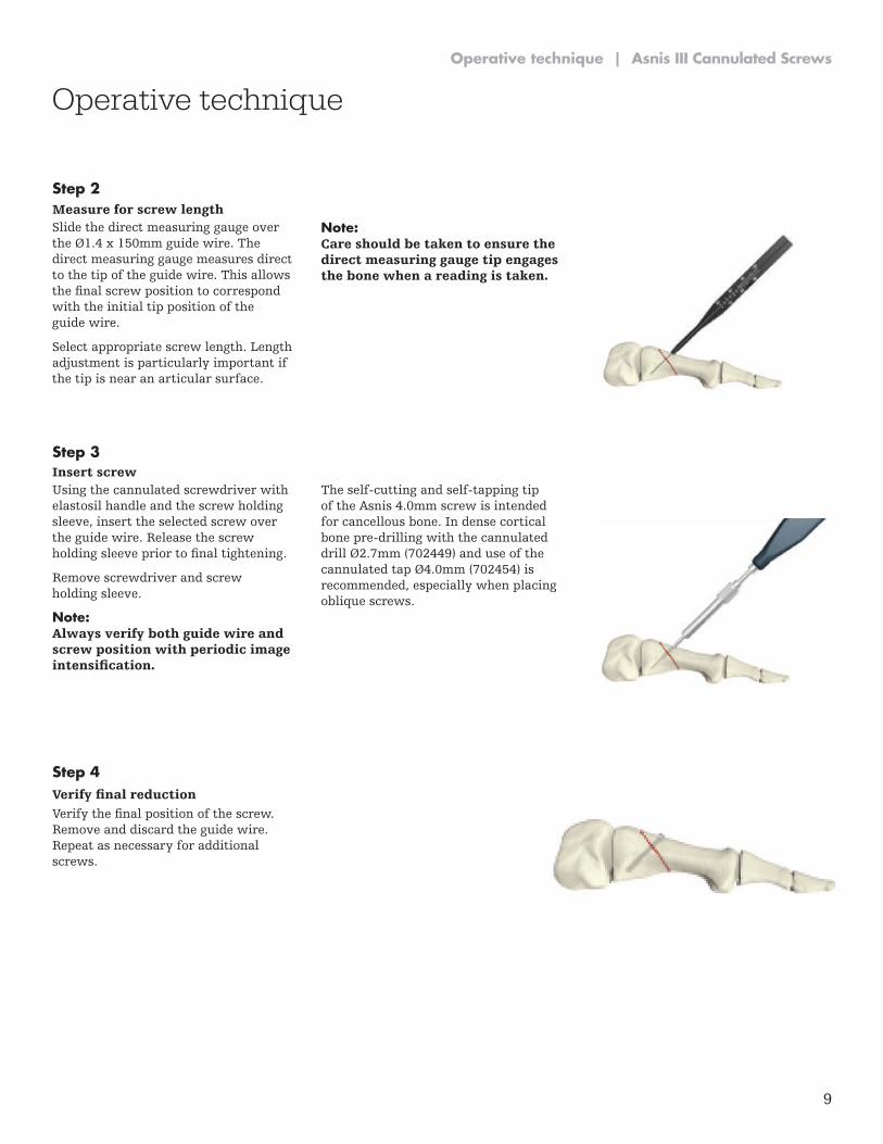
Slide the direct measuring gauge over the Ø1.4 x 150mm guide wire. The direct measuring gauge measures direct to the tip of the guide wire . This allows the final screw position to correspond with the initial tip position of the guide wire .
Select appropriate screw length . Length adjustment is particularly important if the tip is near an articular surface .
Note: Care should be taken to ensure the direct measuring gauge tip engages the bone when a reading is taken.
Using the cannulated screwdriver with elastosil handle and the screw holding sleeve, insert the selected screw over the guide wire . Release the screw holding sleeve prior to final tightening.
Remove screwdriver and screw holding sleeve .
Note: Always verify both guide wire and screw position with periodic image intensification.
The self-cutting and self-tapping tip of the Asnis 4 .0mm screw is intended for cancellous bone . In dense cortical bone pre-drilling with the cannulated drill Ø2 .7mm (702449) and use of the cannulated tap Ø4 .0mm (702454) is recommended, especially when placing oblique screws .
Verify the final position of the screw. Remove and discard the guide wire . Repeat as necessary for additional screws .
Measure for screw length
Insert screw
Verify final reduction
10
Asnis III Cannulated Screws | Operative technique
Medial and lateral malleolar and pilon fractures
Step 1
Optional
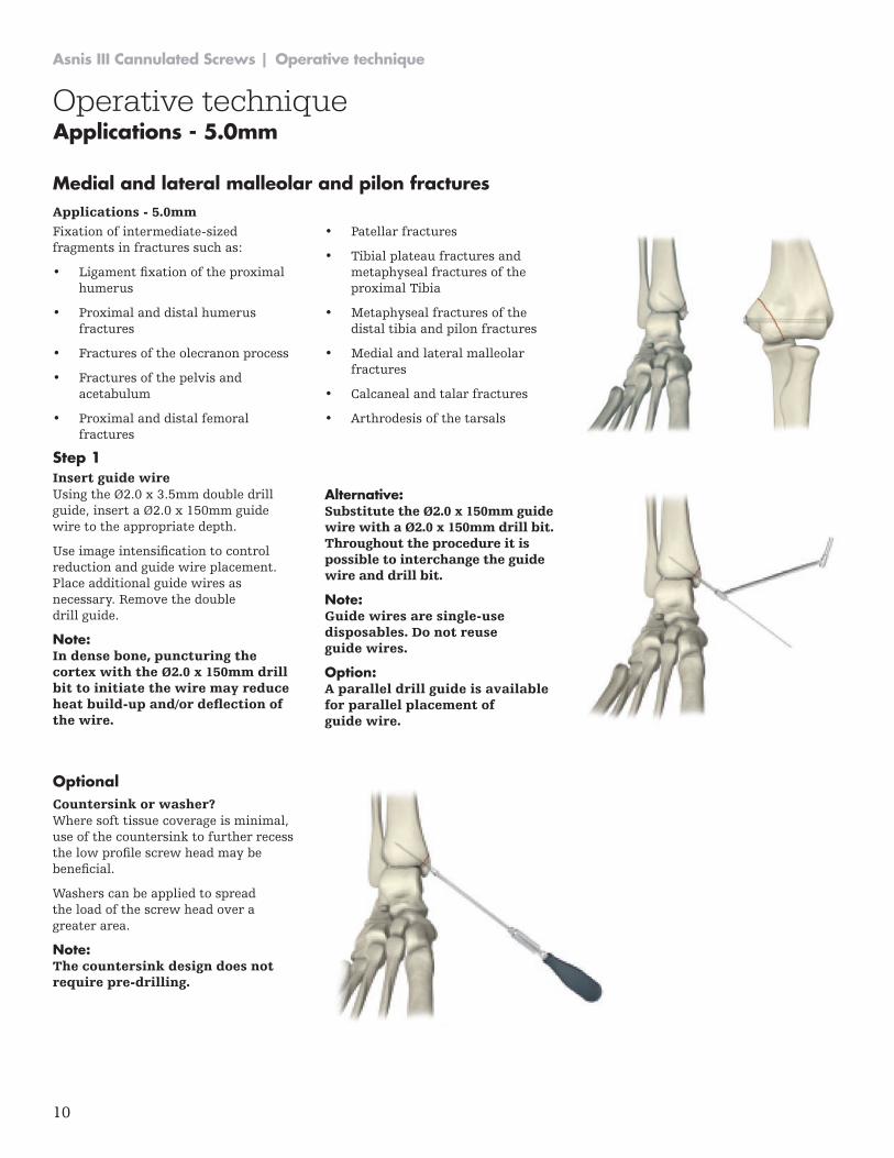
Fixation of intermediate-sized fragments in fractures such as:
• Ligament fixation of the proximal humerus
• Proximal and distal humerus fractures
• Fractures of the olecranon process
• Fractures of the pelvis and acetabulum
• Proximal and distal femoral fractures
• Patellar fractures
• Tibial plateau fractures and metaphyseal fractures of the proximal Tibia
• Metaphyseal fractures of the distal tibia and pilon fractures
• Medial and lateral malleolar fractures
• Calcaneal and talar fractures
• Arthrodesis of the tarsals
Using the Ø2.0 x 3.5mm double drill guide, insert a Ø2.0 x 150mm guide wire to the appropriate depth .
Use image intensification to control reduction and guide wire placement . Place additional guide wires as necessary . Remove the double drill guide .
Note: In dense bone, puncturing the cortex with the Ø2.0 x 150mm drill bit to initiate the wire may reduce heat build-up and/or deflection of the wire.
Alternative: Substitute the Ø2.0 x 150mm guide wire with a Ø2.0 x 150mm drill bit. Throughout the procedure it is possible to interchange the guide wire and drill bit.
Note: Guide wires are single-use disposables. Do not reuse guide wires.
Option: A parallel drill guide is available for parallel placement of guide wire.
Where soft tissue coverage is minimal, use of the countersink to further recess the low profile screw head may be beneficial.
Washers can be applied to spread the load of the screw head over a greater area .
Note: The countersink design does not require pre-drilling.
Applications - 5.0mm
Insert guide wire
Countersink or washer?
Operative techniqueApplications - 5.0mm

11
Operative technique | Asnis III Cannulated Screws
Step 2
Step 3
Step 4
Slide the direct measuring gauge over the Ø2.0 x 150mm guide wire.
The direct measuring gauge measures direct to the tip of the guide wire . This allows the final screw position to correspond with the initial tip position of the guide wire .
Select appropriate screw length . Length adjustment is particularly important if the tip is near an articular surface .
Note: Care should be taken to ensure the direct measuring gauge tip engages the bone when a reading is taken.
Using the cannulated screwdriver with elastosil handle and the screw holding sleeve, insert the selected screw over the guide wire . Release the screw holding sleeve prior to final tightening.
Remove screwdriver and screw holding sleeve .
Note: Always verify both guide wire and screw position with periodic image intensification.
Verify the final position of the screw. Remove and discard the guide wire . Repeat as necessary for additional screws .
Measure for screw length
Insert screw
Verify final reduction
Operative technique

12
Asnis III Cannulated Screws | Operative technique
Operative technique
Intracapsular fractures of the femoral neck
Applications for 6 .5 & 8 .0mm screws include:
• Intracapsular fractures of the femoral neck
• Tibial plateau fractures
• Fractures of the dorsal pelvic ring
• Sacroiliac joint disruptions and other fractures of the pelvis
• Ankle arthrodesis
• Supplementary fixation for fractures of the proximal and distal femur
Parallel guide pins are placed and the appropriate length cannulated screws are advanced over the guide pins .
A full description of this procedure is presented to give the surgeon many of the details for successful intracapsular hip fixation.
Place the patient in a supine position on a fracture table . Traction is then applied with the leg in neutral flexion, 10 degrees abduction and neutral rotation . After the application of
traction, the hip is internally rotated as far as possible using moderate force, then backed off to a position of approximately 20 degrees internal rotation . The reduction is then confirmed by fluoroscopy.
If good alignment but slight distraction of the fracture is present, proceed with the internal fixation and compress the fracture with the compression screws. A six-centimeter straight lateral incision is made, starting at the flair of the greater trochanter and
extending distally. If a closed fracture is not able to be reduced or if significant comminution of the posterior femoral neck is present, then the surgeon should consider open reduction or prosthetic replacement .
The fascia lata and vastus lateralis are then split in line with the incision .
Applications - 6.5 & 8.0mm
2 Intracapsular fractures of the femoral neck . Results of cannulated screw SE Asnis and L Wanek-Sgaglione J Bone Joint Surg Am . 1994;76:1793-1803 .
Screw range
Drills & taps Note
6.5mm Screw
a . Asnis III 4 .9 mm cannulated drill – Ref # 702601 b . Asnis III 6 .5 mm cannulated tap – Ref # 702602 c . Asnis III 6 .5 mm cannulated drill – Ref # 702603
a . Used to drill for the length of the screw to be inserted . b . Used after drilling to tap for the screw to be inserted . c. Used to drill the near cortex only
8.0mm Screw
a . Asnis III 5 .6 mm cannulated drill – Ref # 702611 b . Asnis III 8 .0 mm cannulated tap – Ref # 702612 c . Asnis III 8 .0 mm cannulated drill – Ref # 702613
a . Used to drill for the length of the screw to be inserted . b . Used after drilling to tap for the screw to be inserted . c. Used to drill the near cortex only.
6.5/8.0mm Screw
Asnis III extractor – Ref # 702624
Applications - 6.5 & 8.0mm

13
Operative technique | Asnis III Cannulated Screws
Operative technique
Step 1
Using fluoroscopy, a point is selected at, but not below, the level of the lesser trochanter (See Figure 1) midway between the anterior and posterior femoral cortices . In patients with dense cortical bone, the lateral femoral cortex can be opened with a 3 .2mm drill bit . The guide pin for the most inferior screw is placed through the drill guide, then passed just above the calcar (inferior femoral neck), across the fracture and into the inferior femoral head .
In the lateral view, this guide pin should stay in the mid-line of the femoral neck and head. If fluoroscopy shows that this pin is not in a satisfactory position, then back it out to the cortex and re-direct it without making a new cortical hole . Two-plane fluoroscopy confirms the position of the guide pin .
Multiple guide wire insertion One adjustable parallel pin guide is available (See Figure 2) and two fixed pin guides are available (See Figure 3) . Of the two fixed pin guides, one contains a grid of different sized triangles, the other different sized diamonds .
Three screws using a triangle configuration (one screw distally and two proximally) are recommended for garden I and II fractures, and four screws in a diamond or kite-shape configuration are used for the garden III and IV fractures that require reduction .
The fixed diamond or triangle guide is then placed over the well positioned guide pin and two additional guide pins are placed .
The guide pins can be power driven directly through the cortex, across the fracture and into the femoral head . Pre-drilling at this level is almost never necessary . Check the length and position of the guide pins with fluoroscopy.
Insert guide wire
Fig. 1
Fig. 2
Fig. 3

14
Asnis III Cannulated Screws | Operative technique
Operative technique
The goal for positioning the screws should be to place three or four parallel screws around the periphery of the femoral neck, one in the inferior neck almost along the calcar, one along the mid-posterior neck and one along the mid-anterior neck . A fourth screw should be placed just below the superior neck in those fractures where a reduction was necessary . These will form the optimal triangle or diamond (kite) patterns, which are biomechanically sound .
The diamond is preferred over a rectangular pattern (two distal and two proximal screws) for two reasons: first, the diamond pattern fits best into the elliptical shape of the femoral neck; second, two holes at the same level, at or distal to the level of the lesser trochanter, can leave a weakness and potential for later iatrogenic subtrochanteric fracture . Likewise, when using the triangle pattern, a single screw should be used distally and two screws at the same level more proximally.
Technical tip
Step 2
The screw length is determined by the direct reading depth gauge . If the measurement indicator is in-between lengths, use the shorter length . If the fracture is to be compressed, choose a screw 5mm to 10mm shorter than measured . This will leave room for the threads in the femoral head to advance as the screw lags and the fracture compresses .
Warning: When using a drill or a tap always verify both guide wire and drill or tap position with periodic image intensification.
If the guide wire is jammed in the cannulation of the drill or the tap due to any reason there is an increased risk of perforation of the guide wire into the small pelvis possibly causing life threatening injuries of internal organs.
Measure for screw length
15
Operative technique | Asnis III Cannulated Screws
Operative technique
Step 3
Step 4
Step 5
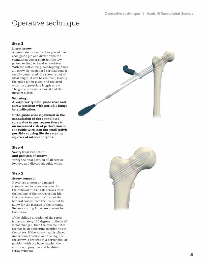
A cannulated screw is then placed over each guide pin and driven with the cannulated power shaft (on the low-power setting) or hand screwdriver . With the self-cutting, self-tapping Asnis III screw tip, even hard cortical bone is readily penetrated . If a screw is not of ideal length, it can be removed, leaving the guide pin in place, and replaced with the appropriate length screw . The guide pins are removed and the incision closed .
Warning: Always verify both guide wire and screw position with periodic image intensification.
If the guide wire is jammed in the cannulation of the cannulated screw due to any reason there is an increased risk of perforation of the guide wire into the small pelvis possibly causing life threatening injuries of internal organs.
Verify the final position of all screws. Remove and discard all guide wires .
Never use a worn or damaged screwdriver to remove screws . In the removal of Asnis III screws after the healing of the intracapsular hip fracture, the screw must re-cut the femoral cortex from the inside out to allow for the passage of the threads . Reverse cutting flutes are present for this reason .
If the oblique direction of the screw (approximately 135 degrees to the shaft) is not changed, then the reverse flutes are not in an opportune position to cut the cortex. If the screw head is placed under some traction and the angle of the screw is brought to a perpendicular position with the bone, cutting the cortex will progress and facilitate screw removal .
Insert screw
Verify final reduction and position of screws
Screw removal

This document is intended solely for the use of healthcare professionals . A surgeon must always rely on his or her own professional clinical judgment when deciding whether to use a particular product when treating a particular patient . Stryker does not dispense medical advice and recommends that surgeons be trained in the use of any particular product before using it in surgery .
The information presented is intended to demonstrate a Stryker product . A surgeon must always refer to the package insert, product label and/or instructions for use, including the instructions for Cleaning and Sterilization (if applicable), before using any Stryker product . Products may not be available in all markets because product availability is subject to the regulatory and/or medical practices in individual markets . Please contact your Stryker representative if you have questions about the availability of Stryker products in your area .
Stryker Corporation or its divisions or other corporate affiliated entities own, use or have applied for the following trademarks or service marks: Asnis, Stryker . All other trademarks are trademarks of their respective owners or holders .
The products listed above are CE marked .
Content ID: AS-ST-2, Rev 2, 11-2016 Copyright © 2016 Stryker
Trauma & Extremities
Manufacturer:
Stryker GmbH Bohnackerweg 1 2545 Selzach Switzerland
stryker .com