ashrae standard energy standard for buildings except buildings library/technical resources/standards...
TRANSCRIPT

ASHRAE STANDARDASHRAE STANDARD
ANSI/ASHRAE/IESNA Addendum r toANSI/ASHRAE/IESNA Standard 90.1-2007
Energy Standard for Buildings Except Low-Rise Residential Buildings
Approved by the ASHRAE Standards Committee on June 6, 2009; by the ASHRAE Board of Directors onJune 24, 2009; by the Illuminating Engineering Society of North America on June 15, 2009; and by the Ameri-can National Standards Institute on June 25, 2009.
This standard is under continuous maintenance by a Standing Standard Project Committee (SSPC) for whichthe Standards Committee has established a documented program for regular publication of addenda or revi-sions, including procedures for timely, documented, consensus action on requests for change to any part ofthe standard. The change submittal form, instructions, and deadlines may be obtained in electronic form fromthe ASHRAE Web site, http://www.ashrae.org, or in paper form from the Manager of Standards. The latest edi-tion of an ASHRAE Standard may be purchased from ASHRAE Customer Service, 1791 Tullie Circle, NE,Atlanta, GA 30329-2305. E-mail: [email protected]. Fax: 404-321-5478. Telephone: 404-636-8400 (world-wide), or toll free 1-800-527-4723 (for orders in US and Canada).
© Copyright 2009 American Society of Heating, Refrigerating and Air-Conditioning Engineers, Inc.
ISSN 1041-2336
American Society of Heating, Refrigeratingand Air-Conditioning Engineers, Inc.
1791 Tullie Circle NE, Atlanta, GA 30329www.ashrae.org
ASHRAE Standing Standard Project Committee 90.1Cognizant TC: TC 7.6, Systems Energy Utilization
SPLS Liaison: Doug ReindlASHRAE Staff Liaison: Steven C. Ferguson
IESNA Liaison: Rita M. Harrold
*Denotes voting member at time of approval for publication.
Schwedler, Mick, Chair* Jim Garrigus* Michael Mehl*
Hydeman, Mark, Vice Chair* Jason Glazer* Harry Misuriello
Skalko, Stephen V., Vice Chair* Chad Groshart Frank Morrison*
Jerine Ahmed* Brian Hahlen Tim Peglow*
Karim Amrane* Pekka Hakkarainen* Eric Richman*
Susan Anderson * Susanna Hanson Michael Rosenberg*
Wagdy Anis* Richard Heinisch* Steven Rosenstock*
Peter Baselici* Ned Heminger* Kenneth Sagan*
Randy Blanchette John Hogan* David Schaaf*
Jeff Boldt* Jonathan Humble Leonard Sciarra*
Dave Branson* Hyman Kaplan* Maria Spinu*
Donald Brundage* Ronald Kurtz* Frank Stanonik*
Ken Brendan* Michael Lane* Jeff Stein
Ron Burton* John Lewis* Christian Taber*
Jim Calm* Richard Lord* Mike Tillou*
Ernest Conrad* Ken Luther Martha VanGeem*
Charles Cottrell* Ronald Majette* Michael Waite*
Craig Drumheller* Itzhak Maor McHenry Wallace*
Keith Emerson* Merle McBride* Daniel Walker
Drake Erbe* James McClendon Richard Watson*
Charles Foster* Raymond McGowan David Weitz*
Allan Fraser* Jerry White*
© 2009, American Society of Heating, Refrigerating and Air-Conditioning Engineers, Inc. (www.ashrae.org). For personal use only. Additional reproduction, distribution, or transmission in either print or digital form is not permitted without ASHRAE’s prior written permission.

SPECIAL NOTE
This American National Standard (ANS) is a national voluntary consensus standard developed under the auspices of theAmerican Society of Heating, Refrigerating and Air-Conditioning Engineers (ASHRAE). Consensus is defined by the AmericanNational Standards Institute (ANSI), of which ASHRAE is a member and which has approved this standard as an ANS, as“substantial agreement reached by directly and materially affected interest categories. This signifies the concurrence of morethan a simple majority, but not necessarily unanimity. Consensus requires that all views and objections be considered, and thatan effort be made toward their resolution.” Compliance with this standard is voluntary until and unless a legal jurisdiction makescompliance mandatory through legislation.
ASHRAE obtains consensus through participation of its national and international members, associated societies, andpublic review.
ASHRAE Standards are prepared by a Project Committee appointed specifically for the purpose of writing the Standard.The Project Committee Chair and Vice-Chair must be members of ASHRAE; while other committee members may or may notbe ASHRAE members, all must be technically qualified in the subject area of the Standard. Every effort is made to balance theconcerned interests on all Project Committees.
The Manager of Standards of ASHRAE should be contacted for:a. interpretation of the contents of this Standard,b. participation in the next review of the Standard,c. offering constructive criticism for improving the Standard, ord. permission to reprint portions of the Standard.
ASHRAE INDUSTRIAL ADVERTISING POLICY ON STANDARDSASHRAE Standards and Guidelines are established to assist industry and the public by offering a uniform method of
testing for rating purposes, by suggesting safe practices in designing and installing equipment, by providing proper definitions of this equipment, and by providing other information that may serve to guide the industry. The creation of ASHRAE Standards and Guidelines is determined by the need for them, and conformance to them is completely voluntary.
In referring to this Standard or Guideline and in marking of equipment and in advertising, no claim shall be made, eitherstated or implied, that the product has been approved by ASHRAE.
DISCLAIMER
ASHRAE uses its best efforts to promulgate Standards and Guidelines for the benefit of the public in light of availableinformation and accepted industry practices. However, ASHRAE does not guarantee, certify, or assure the safety orperformance of any products, components, or systems tested, installed, or operated in accordance with ASHRAE’s Standardsor Guidelines or that any tests conducted under its Standards or Guidelines will be nonhazardous or free from risk.
ASHRAE STANDARDS COMMITTEE 2008–2009
Hugh F. Crowther, ChairSteven T. Bushby, Vice-ChairRobert G. BakerMichael F. BedaDonald L. BrandtPaul W. CabotKenneth W. CooperSamuel D. Cummings, Jr.K. William DeanMartin Dierycxk
Robert G. DoerrAllan B. Fraser
Eli P. Howard, IIINadar R. Jayaraman
Byron W. JonesJay A. Kohler
Carol E. MarriottMerle F. McBride
Frank MyersH. Michael Newman
Douglas T. ReindlLawrence J. Schoen
Boggarm S. SettyBodh R. Subherwal
William F. WalterMichael W. Woodford
David E. Knebel, BOD ExOAndrew K. Persily, CO
Stephanie C. Reiniche, Manager of Standards
© 2009, American Society of Heating, Refrigerating and Air-Conditioning Engineers, Inc. (www.ashrae.org). For personal use only. Additional reproduction, distribution, or transmission in either print or digital form is not permitted without ASHRAE’s prior written permission.

ANSI/ASHRAE/IESNA Addendum r to ANSI/ASHRAE/IESNA Standard 90.1-2007 3
(This foreword is not part of this standard. It is merelyinformative and does not contain requirements necessaryfor conformance to the standard. It has not beenprocessed according to the ANSI requirements for astandard and may contain material that has not beensubject to public review or a consensus process.Unresolved objectors on informative material are notoffered the right to appeal at ASHRAE or ANSI.)
FOREWORD
This addendum changes Informative Appendix G Perfor-mance Rating Method into a Normative Appendix. Addition-ally, some language has been modified to make the AppendixEnforceable.
Note: The entire content of this Appendix changes fromInformative to Normative.
Revise the Standard as follows (IP and SI units):
INFORMATIVE NORMATIVE APPENDIX GPERFORMANCE RATING METHOD
G1. GENERAL
G1.1 Performance Rating Method Scope. This buildingperformance rating method is a modification of the EnergyCost Budget (ECB) Method in Section 11 and is intended foruse in rating the energy efficiency of building designs thatexceed the requirements of this standard. This appendix doesNOT offer an alternative compliance path for minimum stan-dard compliance; that is the intent of Section 11, Energy CostBudget Method.
Rather, this appendix is provided for those wishing to usethe methodology developed for this standard to quantifyperformance that substantially exceeds the requirements ofStandard 90.1. It may be useful shall be used for evaluating theperformance of all such proposed designs, including altera-tions and additions to existing buildings, except designs withno mechanical systems.
G1.2 Performance Rating. This performance ratingmethod requires conformance with the following provisions:
a. All requirements of 5.4, 6.4, 7.4, 8.4, 9.4, and 10.4 aremet. These sections contain the mandatory provisions ofthe standard, and are prerequisites for this rating method.
b. The improved performance of the proposed buildingdesign is calculated in accordance with provisions of thisappendix using the following formula:
Percentage improvement =100 × (Baseline building performance
– Proposed building performance)/Baseline buildingperformance
Notes:
1. Both the proposed building performance and the base-line building performance shall include all end-useload components, such as receptacle and process loads.
2. Neither the proposed building performance nor thebaseline building performance are predictions ofactual energy consumption or costs for the proposeddesign after construction. Actual experience will differfrom these calculations due to variations such as occu-pancy, building operation and maintenance, weather,energy use not covered by this procedure, changes inenergy rates between design of the building and occu-pancy, and the precision of the calculation tool.
G1.3 Trade-Off Limits. When the proposed modificationsapply to less than the whole building, only parameters relatedto the systems to be modified shall be allowed to vary. Param-eters relating to unmodified existing conditions or to futurebuilding components shall be identical for determining boththe baseline building performance and the proposed buildingperformance. Future building components shall meet the pre-scriptive requirements of Sections 5.5, 6.5, 7.5, 9.5, and 9.6.
G1.4 Documentation Requirements. Simulated perfor-mance shall be documented, and documentation shall be sub-mitted to the rating authority. The information shall besubmitted in a report and shall include the following:
a. A brief description of the project, the key energy effi-ciency improvements, the simulation program used, theversion of the simulation program, and the results of theenergy analysis. This summary shall contain the cCalcu-lated values for the baseline building performance, theproposed building performance, and the percentageimprovement.
b. An overview of the project that includes: the number ofstories (above and below grade), the typical floor size, theuses in the building (e.g., office, cafeteria, retail, parking,etc.), the gross area of each use, and whether each use isconditioned space.
c. A list of the energy-related features that are included inthe design and on which the performance rating is based.This list shall document all energy features that differbetween the models used in the baseline building perfor-mance and proposed building performance calculations.
d. A list showing compliance for the proposed design withall the requirements of 5.4, 6.4, 7.4, 8.4, 9.4, and 10.4(mandatory provisions).
e. A list identifying those aspects of the proposed design thatare less stringent than the requirements of 5.5, 6.5, 7.5,9.5, and 9.6 (prescriptive provisions).
f. A table with a summary by end use of the energy cost sav-ings in the proposed building performance.
g. A site plan showing all adjacent buildings and topographywhich may shade the proposed building (with estimatedheight or number of stories).
h. Building elevations and floor plans (schematic is accept-able).
Addendum r to 90.1-2007
© 2009, American Society of Heating, Refrigerating and Air-Conditioning Engineers, Inc. (www.ashrae.org). For personal use only. Additional reproduction, distribution, or transmission in either print or digital form is not permitted without ASHRAE’s prior written permission.
4 ANSI/ASHRAE/IESNA Addendum r to ANSI/ASHRAE/IESNA Standard 90.1-2007
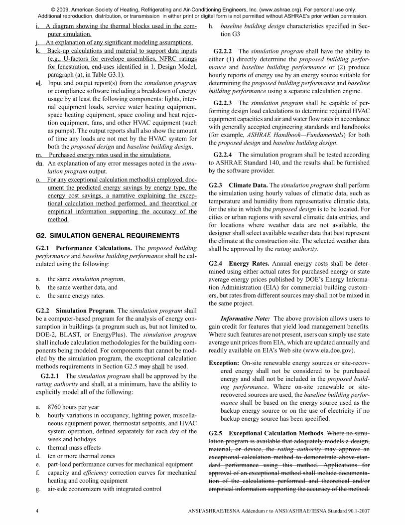
i. A diagram showing the thermal blocks used in the com-puter simulation.
j. An explanation of any significant modeling assumptions.k. Back-up calculations and material to support data inputs
(e.g., U-factors for envelope assemblies, NFRC ratingsfor fenestration, end-uses identified in 1. Design Model,paragraph (a), in Table G3.1).
cl. Input and output report(s) from the simulation programor compliance software including a breakdown of energyusage by at least the following components: lights, inter-nal equipment loads, service water heating equipment,space heating equipment, space cooling and heat rejec-tion equipment, fans, and other HVAC equipment (suchas pumps). The output reports shall also show the amountof time any loads are not met by the HVAC system forboth the proposed design and baseline building design.
m. Purchased energy rates used in the simulations.dn. An explanation of any error messages noted in the simu-
lation program output.o. For any exceptional calculation method(s) employed, doc-
ument the predicted energy savings by energy type, theenergy cost savings, a narrative explaining the excep-tional calculation method performed, and theoretical orempirical information supporting the accuracy of themethod.
G2. SIMULATION GENERAL REQUIREMENTS
G2.1 Performance Calculations. The proposed buildingperformance and baseline building performance shall be cal-culated using the following:
a. the same simulation program,b. the same weather data, andc. the same energy rates.
G2.2 Simulation Program. The simulation program shallbe a computer-based program for the analysis of energy con-sumption in buildings (a program such as, but not limited to,DOE-2, BLAST, or EnergyPlus). The simulation programshall include calculation methodologies for the building com-ponents being modeled. For components that cannot be mod-eled by the simulation program, the exceptional calculationmethods requirements in Section G2.5 may shall be used.
G2.2.1 The simulation program shall be approved by therating authority and shall, at a minimum, have the ability toexplicitly model all of the following:
a. 8760 hours per yearb. hourly variations in occupancy, lighting power, miscella-
neous equipment power, thermostat setpoints, and HVACsystem operation, defined separately for each day of theweek and holidays
c. thermal mass effectsd. ten or more thermal zones e. part-load performance curves for mechanical equipmentf. capacity and efficiency correction curves for mechanical
heating and cooling equipmentg. air-side economizers with integrated control
h. baseline building design characteristics specified in Sec-tion G3
G2.2.2 The simulation program shall have the ability toeither (1) directly determine the proposed building perfor-mance and baseline building performance or (2) producehourly reports of energy use by an energy source suitable fordetermining the proposed building performance and baselinebuilding performance using a separate calculation engine.
G2.2.3 The simulation program shall be capable of per-forming design load calculations to determine required HVACequipment capacities and air and water flow rates in accordancewith generally accepted engineering standards and handbooks(for example, ASHRAE Handbook—Fundamentals) for boththe proposed design and baseline building design.
G2.2.4 The simulation program shall be tested accordingto ASHRAE Standard 140, and the results shall be furnishedby the software provider.
G2.3 Climate Data. The simulation program shall performthe simulation using hourly values of climatic data, such astemperature and humidity from representative climatic data,for the site in which the proposed design is to be located. Forcities or urban regions with several climatic data entries, andfor locations where weather data are not available, thedesigner shall select available weather data that best representthe climate at the construction site. The selected weather datashall be approved by the rating authority.
G2.4 Energy Rates. Annual energy costs shall be deter-mined using either actual rates for purchased energy or stateaverage energy prices published by DOE’s Energy Informa-tion Administration (EIA) for commercial building custom-ers, but rates from different sources may shall not be mixed inthe same project.
Informative Note: The above provision allows users togain credit for features that yield load management benefits.Where such features are not present, users can simply use stateaverage unit prices from EIA, which are updated annually andreadily available on EIA’s Web site (www.eia.doe.gov).
Exception: On-site renewable energy sources or site-recov-ered energy shall not be considered to be purchasedenergy and shall not be included in the proposed build-ing performance. Where on-site renewable or site-recovered sources are used, the baseline building perfor-mance shall be based on the energy source used as thebackup energy source or on the use of electricity if nobackup energy source has been specified.
G2.5 Exceptional Calculation Methods. Where no simu-lation program is available that adequately models a design,material, or device, the rating authority may approve anexceptional calculation method to demonstrate above-stan-dard performance using this method. Applications forapproval of an exceptional method shall include documenta-tion of the calculations performed and theoretical and/orempirical information supporting the accuracy of the method.
© 2009, American Society of Heating, Refrigerating and Air-Conditioning Engineers, Inc. (www.ashrae.org). For personal use only. Additional reproduction, distribution, or transmission in either print or digital form is not permitted without ASHRAE’s prior written permission.

ANSI/ASHRAE/IESNA Addendum r to ANSI/ASHRAE/IESNA Standard 90.1-2007 5
When the simulation program does not model a design,material, or device of the proposed design, an ExceptionalCalculation Method shall be used if approved by the RatingAuthority. If there are multiple designs, materials or devicesthat the simulation program does not model, each shall becalculated separately and Exceptional Savings determined foreach. At no time shall the total Exceptional Savings constitutemore than one-half of the difference between the baselinebuilding performance and the proposed building perfor-mance. All applications for approval of an exceptional methodshall include:
a. step-by-step documentation of the Exceptional Calcula-tion Method performed detailed enough to reproduce theresults;
b. copies of all spreadsheets used to perform the calcula-tions;
c. a sensitivity analysis of energy consumption when each ofthe input parameters is varied from half to double thevalue assumed;
d. the calculations shall be performed on a time step basisconsistent with the simulation program used;
e. the Performance Rating calculated with and without theExceptional Calculation Method;
G3. CALCULATION OF THE PROPOSED AND BASELINE BUILDING PERFORMANCE
G3.1 Building Performance Calculations. The simulationmodel for calculating the proposed and baseline building per-formance shall be developed in accordance with the require-ments in Table G3.1.
G3.1.1 Baseline HVAC System Type and Description.HVAC systems in the baseline building design shall be basedon usage, number of floors, conditioned floor area, and heat-ing source as specified in Table G3.1.1A and shall conformwith the system descriptions in Table G3.1.1B. For systems 1,2, 3, and 4, each thermal block shall be modeled with its own
HVAC system. For systems 5, 6, 7, and 8, each floor shall bemodeled with a separate HVAC system. Floors with identicalthermal blocks can be grouped for modeling purposes.
Exceptions:
a. Use additional system type(s) for nonpredominantconditions (i.e., residential/nonresidential or heatingsource) if those conditions apply to more than 20,000ft2 (1900 m2) of conditioned floor area.
b. If the baseline HVAC system type is 5, 6, 7, or 8, useseparate single-zone systems conforming with therequirements of System 3 or System 4 (depending onbuilding heating source) for any spaces that haveoccupancy or process loads or schedules that differsignificantly from the rest of the building. Peak ther-mal loads that differ by 10 Btu/h·ft2 (31.2 W/m2) ormore from the average of other spaces served by thesystem or schedules that differ by more than 40equivalent full-load hours per week from otherspaces served by the system are considered to differsignificantly. Examples where this exception may beapplicable include, but are not limited to, computerserver rooms, natatoriums, and continually occupiedsecurity areas.
c. If the baseline HVAC system type is 5, 6, 7, or 8, useseparate single-zone systems conforming with therequirements of System 3 or System 4 (depending onbuilding heat source) for any zones having specialpressurization relationships, cross-contaminationrequirements, or code-required minimum circulationrates.
d. For laboratory spaces with a minimum of 5000 cfm(2400 L/s) of exhaust, use system type 5 or 7 thatreduce the exhaust and makeup air volume to 50% ofdesign values during unoccupied periods. For all-electric buildings, the heating shall be electric resis-tance.
TABLE G3.1 Modeling Requirements for Calculating Proposed and Baseline Building Performance
No. Proposed Building Performance Baseline Building Performance
1. Design Model
a. The simulation model of the proposed design shall be consistent with the design documents, including proper accounting of fenestration and opaque envelope types and areas; interior lighting power and controls; HVAC system types, sizes, and controls; and service water heating systems and controls. All end-use load components within and associated with the building shall be modeled, including, but not limited to, exhaust fans, parking garage ventilation fans, snow-melt and freeze-protection equipment, facade lighting, swimming pool heaters and pumps, elevators and escalators, refrigeration, and cooking. Where the simulation pro-gram does not specifically model the functionality of the installed system, spreadsheets or other documentation of the assumptions shall be used to generate the power demand and operating schedule of the systems.
b. All conditioned spaces in the proposed design shall be simulated as being both heated and cooled even if no heating or cooling system is to be installed, and temperature and humidity control setpoints and schedules shall be the same for proposed and baseline building designs.
c. When the performance rating method is applied to buildings in which energy-related features have not yet been designed (e.g., a lighting system), those yet-to-be-designed features shall be described in the proposed design exactly as they are defined in the baseline building design. Where the space classification for a space is not known, the space shall be categorized as an office space.
The baseline building design shall be modeled with the same number of floors and identical conditioned floor area as the proposed design.
© 2009, American Society of Heating, Refrigerating and Air-Conditioning Engineers, Inc. (www.ashrae.org). For personal use only. Additional reproduction, distribution, or transmission in either print or digital form is not permitted without ASHRAE’s prior written permission.

6 ANSI/ASHRAE/IESNA Addendum r to ANSI/ASHRAE/IESNA Standard 90.1-2007
No. Proposed Building Performance Baseline Building Performance
2. Additions and Alterations
It is acceptable to predict performance using building models that exclude parts of the existing building provided that all of the following conditions are met:a. Work to be performed in excluded parts of the building shall meet the require-
ments of Sections 5 through 10. b. Excluded parts of the building are served by HVAC systems that are entirely sep-
arate from those serving parts of the building that are included in the building model.
c. Design space temperature and HVAC system operating setpoints and schedules on either side of the boundary between included and excluded parts of the build-ing are essentially the same.
d. If a declining block or similar utility rate is being used in the analysis and the excluded and included parts of the building are on the same utility meter, the rate shall reflect the utility block or rate for the building plus the addition.
Same as Proposed Design
3. Space Use Classification
Usage shall be specified using the building type or space type lighting classifications in accordance with Section 9.5.1 or 9.6.1. The user shall specify the space use classi-fications using either the building type or space type categories but shall not combine the two types of categories. More than one building type category may be used in a building if it is a mixed-use facility. If space type categories are used, the user may simplify the placement of the various space types within the building model, pro-vided that building-total areas for each space type are accurate.
Same as Proposed Design
4. Schedules
Schedules capable of modeling hourly variations in occupancy, lighting power, mis-cellaneous equipment power, thermostat setpoints, and HVAC system operation shall be used. The schedules shall be typical of the proposed building type as determined by the designer and approved by the rating authority.
HVAC Fan Schedules. Schedules for HVAC fans that provide outdoor air for venti-lation shall run continuously whenever spaces are occupied and shall be cycled on and off to meet heating and cooling loads during unoccupied hours.
Exceptions: a. Where no heating and/or cooling system is to be installed and a heating or
cooling system is being simulated only to meet the requirements described in this table, heating and/or cooling system fans shall not be simulated as running continuously during occupied hours but shall be cycled on and off to meet heating and cooling loads during all hours.
b. HVAC fans shall remain on during occupied and unoccupied hours in spaces that have health and safety mandated minimum ventilation require-ments during unoccupied hours.
Same as Proposed DesignException: Schedules may be allowed to differ between proposed design and baseline building design when necessary to model nonstandard effi-ciency measures, provided that the revised schedules have the approval of the rating authority. Measures that may warrant use of different schedules include, but are not limited to, automatic lighting controls, automatic natural ventilation controls, automatic demand control ventilation controls, and mea-sures automatic controls that reduce service water heating loads. In no case shall schedules differ where the controls are manual (e.g., manual operation of light switches or manual operation of windows).
TABLE G3.1 Modeling Requirements for Calculating Proposed and Baseline Building Performance (continued)
© 2009, American Society of Heating, Refrigerating and Air-Conditioning Engineers, Inc. (www.ashrae.org). For personal use only. Additional reproduction, distribution, or transmission in either print or digital form is not permitted without ASHRAE’s prior written permission.

ANSI/ASHRAE/IESNA Addendum r to ANSI/ASHRAE/IESNA Standard 90.1-2007 7
No. Proposed Building Performance Baseline Building Performance
5. Building Envelope
All components of the building envelope in the proposed design shall be modeled as shown on architectural drawings or as built for existing building envelopes.
Exceptions: The following building elements are permitted to differ from architectural drawings. a. All uninsulated assemblies (e.g., projecting balconies, perimeter edges of
intermediate floor slabs, concrete floor beams over parking garages, roof parapet) shall be separately modeled using either of the following tech-niques:1. Separate model of each of these assemblies within the energy simula-tion model.2. Separate calculation of the U-factor for each of these assemblies. The U-factors of these assemblies are then averaged with larger adjacent sur-faces using an area-weighted average method. This average U-factor is modeled within the energy simulation model.Any other envelope assembly that covers less than 5% of the total area of that assembly type (e.g., exterior walls) need not be separately described provided that it is similar to an assembly being modeled. If not separately described, the area of an envelope assembly shall be added to the area of an assembly of that same type with the same orientation and thermal properties.
b. Exterior surfaces whose azimuth orientation and tilt differ by less than 45 degrees and are otherwise the same may be described as either a single sur-face or by using multipliers.
c. For exterior roofs, the roof surface may shall be modeled with a reflectance of 0.45 if the reflectance of the proposed design roof is greater than 0.70 and its emittance is greater than 0.75 or has a minimum SRI of 82. Reflec-tance values shall be based on testing in accordance with ASTM C1549, ASTM E903, or ASTM E1918, and emittance values shall be based on testing in accordance with ASTM C1371 or ASTM E408, and SRI shall be based on ASTM E1980 calculated at medium wind speed. All other roof surfaces shall be modeled with a reflectance of 0.30.
d. Manual fenestration shading devices such as blinds or shades shall not be modeled or not modeled, the same as in the baseline. Automatically con-trolled fenestration shades or blinds may shall be modeled. Permanent shading devices such as fins, overhangs, and light shelves may shall be modeled.
Equivalent dimensions shall be assumed for each exterior envelope component type as in the proposed design; i.e., the total gross area of exterior walls shall be the same in the proposed and baseline building designs. The same shall be true for the areas of roofs, floors, and doors, and the exposed perimeters of concrete slabs on grade shall also be the same in the proposed and baseline building designs. The following additional requirements shall apply to the modeling of the baseline building design:
Exceptions:a. Orientation. The baseline building performance shall be generated by simu-
lating the building with its actual orientation and again after rotating the entire building 90, 180, and 270 degrees, then averaging the results. The building shall be modeled so that it does not shade itself.a. If it can be demonstrated to the satisfaction of the Program Evaluator
that the building orientation is dictated by site considerations.b. Buildings where the vertical fenestration area on each orientation varies
by less than 5%.
b. Opaque Assemblies. Opaque assemblies used for new buildings or additions shall conform with the following common, lightweight assembly types and shall match the appropriate assembly maximum U-factors in Tables 5.5-1 through 5.5-8:
• Roofs—Insulation entirely above deck• Above-grade walls—Steel-framed• Floors—Steel-joist• Opaque door types shall match the proposed design and conform to the U-fac-tor requirements from the same tables. • Slab-on-grade floors shall match the F-factor for unheated slabs from the same tables.Opaque assemblies used for alterations shall conform with Section 5.1.3.c. Vertical Fenestration. Vertical fenestration areas for new buildings and
additions shall equal that in the proposed design or 40% of gross above-grade wall area, whichever is smaller, and shall be distributed on each face of the building in the same proportions in the proposed design. Fenestra-tion U-factors shall match the appropriate requirements in Tables 5.5-1 through 5.5-8 for the applicable vertical glazing percentage for Ufixed. Fenestration SHGC shall match the appropriate requirements in Tables 5.5-1 through 5.5-8 using the value for SHGCall for the applicable vertical glazing percentage. All vertical glazing shall be modeled as fixed and shall be assumed to be flush with the exterior wall, and no shading projections shall be modeled. Manual window shading devices such as blinds or shades are not required to shall not be modeled. The fenestration areas for envelope alterations shall reflect the limitations on area, U-factor, and SHGC as described in Section 5.1.3.
d. Skylights and Glazed Smoke Vents. Skylight area shall be equal to that in the proposed building design or 5% of the gross roof area that is part of the building envelope, whichever is smaller. If the skylight area of the proposed building design is greater than 5% of the gross roof area, baseline skylight area shall be decreased by an identical percentage in all roof components in which skylights are located to reach the 5% skylight-to-roof ratio. Skylight orientation and tilt shall be the same as in the proposed building design. Sky-light U-factor and SHGC properties shall match the appropriate requirements in Tables 5.5-1 through 5.5-8.
e. Roof albedo. All roof surfaces shall be modeled with a reflectivity of 0.30. f. Existing Buildings. For existing building envelopes, the baseline building
design shall reflect existing conditions prior to any revisions that are part of the scope of work being evaluated.
TABLE G3.1 Modeling Requirements for Calculating Proposed and Baseline Building Performance (continued)
© 2009, American Society of Heating, Refrigerating and Air-Conditioning Engineers, Inc. (www.ashrae.org). For personal use only. Additional reproduction, distribution, or transmission in either print or digital form is not permitted without ASHRAE’s prior written permission.

8 ANSI/ASHRAE/IESNA Addendum r to ANSI/ASHRAE/IESNA Standard 90.1-2007
No. Proposed Building Performance Baseline Building Performance
6. Lighting
Lighting power in the proposed design shall be determined as follows:a. Where a complete lighting system exists, the actual lighting power for each ther-
mal block shall be used in the model. b. Where a lighting system has been designed, lighting power shall be determined
in accordance with Sections 9.1.3 and 9.1.4.c. Where lighting neither exists nor is specified, lighting power shall be determined
in accordance with the Building Area Method for the appropriate building type.d. Lighting system power shall include all lighting system components shown or
provided for on the plans (including lamps and ballasts and task and furniture-mounted fixtures).
Exception: For multifamily dwelling units, hotel/motel guest rooms, and other spaces in which lighting systems are connected via receptacles and are not shown or provided for on building plans, assume identical lighting power for the proposed and baseline building designs in the simulations.
e. Lighting power for parking garages and building facades shall be modeled. f. Credit may be taken for the use of automatic controls for daylight utilization but
only if their operation is either modeled directly in the building simulation ormodeled in the building simulation through schedule adjustments determined bya separate daylighting analysis approved by the rating authority.
g. For automatic lighting controls in addition to those required for minimum codecompliance under Section 9.4.1, credit may be taken for automatically con-trolled systems by reducing the connected lighting power by the applicable per-centages listed in Table G3.2. Alternatively, credit may be taken for thesedevices by modifying the lighting schedules used for the proposed design, pro-vided that credible technical documentation for the modifications are providedto the rating authority.
Lighting power in the baseline building design shall be determined using the same categorization procedure (building area or space function) and categories as the proposed design with lighting power set equal to the maximum allowed for the cor-responding method and category in Section 9.2. Lighting shall be modeled having the automatic and manual controls in Section 9.4. No additional automatic lighting controls (e.g., programmable controls or automatic controls for daylight utiliza-tion) shall be modeled in the baseline building design, as the lighting schedules used are understood to reflect the mandatory control requirements in this standard.
7. Thermal Blocks—HVAC Zones Designed
Where HVAC zones are defined on HVAC design drawings, each HVAC zone shall be modeled as a separate thermal block.
Exception: Different HVAC zones may be combined to create a single thermal block or identical thermal blocks to which multipliers are applied, provided that all of the following conditions are met:a. The space use classification is the same throughout the thermal block.b. All HVAC zones in the thermal block that are adjacent to glazed exterior
walls face the same orientation or their orientations vary by less than 45degrees.
c. All of the zones are served by the same HVAC system or by the same kindof HVAC system.
Same as Proposed Design.
8. Thermal Blocks—HVAC Zones Not Designed
Where the HVAC zones and systems have not yet been designed, thermal blocks shall be defined based on similar internal load densities, occupancy, lighting, thermal and space temperature schedules, and in combination with the following guidelines:a. Separate thermal blocks shall be assumed for interior and perimeter spaces. Inte-
rior spaces shall be those located greater than 15 ft (5 m) from an exterior wall.Perimeter spaces shall be those located within 15 ft (5 m) of an exterior wall.
b. Separate thermal blocks shall be assumed for spaces adjacent to glazed exteriorwalls; a separate zone shall be provided for each orientation, except that orienta-tions that differ by less than 45 degrees may be considered to be the same orienta-tion. Each zone shall include all floor area that is 15 ft (5 m) or less from a glazedperimeter wall, except that floor area within15 ft (5 m) of glazed perimeter wallshaving more than one orientation shall be divided proportionately between zones.
c. Separate thermal blocks shall be assumed for spaces having floors that are in con-tact with the ground or exposed to ambient conditions from zones that do notshare these features.
d. Separate thermal blocks shall be assumed for spaces having exterior ceiling or roofassemblies from zones that do not share these features.
Same as Proposed Design.
9. Thermal Blocks—Multifamily Residential Buildings
Residential spaces shall be modeled using at least one thermal block per dwelling unit, except that those units facing the same orientations may be combined into one thermal block. Corner units and units with roof or floor loads shall only be combined with units sharing these features.
Same as Proposed Design.
TABLE G3.1 Modeling Requirements for Calculating Proposed and Baseline Building Performance (continued)
© 2009, American Society of Heating, Refrigerating and Air-Conditioning Engineers, Inc. (www.ashrae.org). For personal use only. Additional reproduction, distribution, or transmission in either print or digital form is not permitted without ASHRAE’s prior written permission.

ANSI/ASHRAE/IESNA Addendum r to ANSI/ASHRAE/IESNA Standard 90.1-2007 9
No. Proposed Building Performance Baseline Building Performance
10. HVAC Systems
The HVAC system type and all related performance parameters in the proposed design, such as equipment capacities and efficiencies, shall be determined as follows:a. Where a complete HVAC system exists, the model shall reflect the actual system
type using actual component capacities and efficiencies.b. Where an HVAC system has been designed, the HVAC model shall be consistent
with design documents. Mechanical equipment efficiencies shall be adjustedfrom actual design conditions to the standard rating conditions specified in Sec-tion 6.4.1 if required by the simulation model.
c. Where no heating system exists or no heating system has been specified, theheating system classification shall be assumed to be electric, and the system char-acteristics shall be identical to the system modeled in the baseline buildingdesign.
d. Where no cooling system exists or no cooling system has been specified, thecooling system shall be identical to the system modeled in the baseline buildingdesign.
The HVAC system(s) in the baseline building design shall be of the type and description specified in Section G3.1.1, shall meet the general HVAC system requirements specified in Section G3.1.2, and shall meet any system-specific requirements in Section G3.1.3 that are applicable to the baseline HVAC system type(s).
11. Service Hot-Water Systems
The service hot-water system type and all related performance parameters, such as equipment capacities and efficiencies, in the proposed design shall be determined as follows:a. Where a complete service hot-water system exists, the proposed design shall
reflect the actual system type using actual component capacities and efficiencies. b. Where a service hot-water system has been specified, the service hot-water
model shall be consistent with design documents. c. Where no service hot-water system exists or has been specified but the building
will have service hot-water loads, a service hot-water system shall be modeledthat matches the system in the baseline building design and serves the same hot-water loads.
d. For buildings that will have no service hot-water loads, no service hot-water sys-tem shall be modeled.
The service hot-water system in the baseline building design shall use the same energy source as the corresponding system in the proposed design and shall con-form with the following conditions:a. Where the complete service hot-water system exists, the baseline building
design shall reflect the actual system type using the actual component capac-ities and efficiencies.
b. Where a new service hot-water system has been specified, the system shallbe sized according to the provisions of Section 7.4.1 and the equipment shallmatch the minimum efficiency requirements in Section 7.4.2. Where theenergy source is electricity, the heating method shall be electrical resistance.
c. Where no service hot-water system exists or has been specified but the build-ing will have service hot-water loads, a service water system(s) using electri-cal-resistance heat and matching minimum efficiency requirements ofSection 7.4.2 shall be assumed and modeled identically in the proposed andbaseline building designs.
d. For buildings that will have no service hot-water loads, no service hot-waterheating shall be modeled.
e. Where a combined system has been specified to meet both space heating andservice water heating loads, the baseline building system shall use separatesystems meeting the minimum efficiency requirements applicable to eachsystem individually.
f. For large, 24-hour-per-day facilities that meet the prescriptive criteria for useof condenser heat recovery systems described in Section 6.5.6.2, a systemmeeting the requirements of that section shall be included in the baselinebuilding design regardless of the exceptions to Section 6.5.6.2. Exception: If a condenser heat recovery system meeting the requirements described in Section 6.5.6.2 cannot be modeled, the requirement for including such a system in the actual building shall be met as a prescriptive requirement in accordance with Section 6.5.6.2, and no heat-recovery sys-tem shall be included in the proposed or baseline building designs.
g. Service hot-water energy consumption shall be calculated explicitly basedupon the volume of service hot water required and the entering makeupwater and the leaving service hot-water temperatures. Entering water temper-atures shall be estimated based upon the location. Leaving temperatures shallbe based upon the end-use requirements.
h. Where recirculation pumps are used to ensure prompt availability of servicehot water at the end use, the energy consumption of such pumps shall be cal-culated explicitly.
i. Service water loads and usage shall be the same for both the baseline build-ing design and the proposed design and shall be documented by the calcula-tion procedures described in Section 7.4.1.Exceptions:1. Service hot-water usage can be demonstrated to be reduced by docu-
mented water conservation measures that reduce the physical volume ofservice water required. Examples include low-flow shower heads. Suchreduction shall be demonstrated by calculations.
2. Service hot-water energy consumption can be demonstrated to bereduced by reducing the required temperature of service mixed water, byincreasing the temperature, or by increasing the temperature of the enter-ing makeup water. Examples include alternative sanitizing technologiesfor dishwashing and heat recovery to entering makeup water. Such reduc-tion shall be demonstrated by calculations.
TABLE G3.1 Modeling Requirements for Calculating Proposed and Baseline Building Performance (continued)
© 2009, American Society of Heating, Refrigerating and Air-Conditioning Engineers, Inc. (www.ashrae.org). For personal use only. Additional reproduction, distribution, or transmission in either print or digital form is not permitted without ASHRAE’s prior written permission.

10 ANSI/ASHRAE/IESNA Addendum r to ANSI/ASHRAE/IESNA Standard 90.1-2007
G3.1.1.1 Purchased Heat. For systems using purchasedhot water or steam, hot water or steam costs shall be based onactual utility rates, and on-site boilers shall not be modeled inthe baseline building design.
G3.1.2 General Baseline HVAC System Requirements.HVAC systems in the baseline building design shall conformwith the general provisions in this section.
G3.1.2.1 Equipment Efficiencies. All HVAC equipmentin the baseline building design shall be modeled at the mini-mum efficiency levels, both part load and full load, in accor-dance with Section 6.4. Where efficiency ratings, such as EERand COP, include fan energy, the descriptor shall be broken
down into its components so that supply fan energy can bemodeled separately.
G3.1.2.2 Equipment Capacities. The equipment capaci-ties for the baseline building design shall be based on sizingruns for each orientation (per Table G3.1, No. 5a) and shall beoversized by 15% for cooling and 25% for heating, i.e., theratio between the capacities used in the annual simulationsand the capacities determined by the sizing runs shall be 1.15for cooling and 1.25 for heating. Unmet load hours for theproposed design or baseline building designs shall not exceed300 (of the 8760 hours simulated), and unmet load hours forthe proposed design shall not exceed the number of unmetload hours for the baseline building design by more than 50.
No. Proposed Building Performance Baseline Building Performance
3. Service hot-water usage can be demonstrated to be reduced by reducingthe hot fraction of mixed water to achieve required operational tempera-ture. Examples include shower or laundry heat recovery to incomingcold-water supply, reducing the hot-water fraction required to meetrequired mixed-water temperature. Such reduction shall be demonstratedby calculations.
12. Receptacle and Other Loads
Receptacle and process loads, such as those for office and other equipment, shall be estimated based on the building type or space type category and shall be assumed to be identical in the proposed and baseline building designs, except as specifically authorized by the rating authority. These loads shall be included in simulations of the building and shall be included when calculating the baseline building performance and proposed building performance.
Other systems, such as motors covered by Section 10, and miscellaneous loads shall be modeled as identical to those in the proposed design including schedules of operation and control of the equipment. Where there are specific efficiency requirements in Section 10, these systems or components shall be modeled as having the lowest efficiency allowed by those requirements.Where no efficiency requirements exist, power and energy rating or capacity of the equipment shall be identical between the baseline building and the proposed design with the follow-ing exception: variations of the power requirements, schedules, or control sequences of the equipment modeled in the baseline building from those in the proposed design may shall be allowed by the rating authority based upon docu-mentation that the equipment installed in the proposed design represents a signif-icant verifiable departure from documented conventional practice. The burden of this documentation is to demonstrate that accepted conventional practice would result in baseline building equipment different from that installed in the proposed design. Occupancy and occupancy schedules may shall not be changed.
13. Modeling Limitations to the Simulation ProgramIf the simulation program cannot model a component or system included in the pro-posed design explicitly, substitute a thermodynamically similar component model that can approximate the expected performance of the component that cannot be modeled explicitly.
Same as Proposed Design.
14. Exterior Conditions
a. Shading by adjacent structures and terrain:The effect that structures and significant vegetation or topographical features haveon the amount of solar radiation being received by a structure shall be adequatelyreflected in the computer analysis.
All elements whose effective height is greater than their distance from a proposedbuilding and whose width facing the proposed building is greater than one-thirdthat of the proposed building shall be accounted for in the analysis.If the computer program has a subroutine to simulate shading by adjacent struc-tures, then this option shall be used.
If the computer program does not have a subroutine to simulate shading by adja-cent structures, then any portion of a structure that is shaded most of the time isallowed to be modeled as having a north-facing orientation.
b. Ground temperatures for below-grade wall and basement floor heat losscalculations:It is acceptable to use either an annual average ground temperature or monthlyaverage ground temperatures for calculation of heat loss through below-gradewalls and basement floors.
c. Water main temperatures for service water heating calculations:It is acceptable to use either an annual water main supply temperature or monthlyaverage water main supply temperatures for calculating service water heating. Ifannual or monthly water main supply temperatures are not available from the localwater utility, annual average ground temperatures may be used.
Same as Proposed Design.
TABLE G3.1 Modeling Requirements for Calculating Proposed and Baseline Building Performance (continued)
© 2009, American Society of Heating, Refrigerating and Air-Conditioning Engineers, Inc. (www.ashrae.org). For personal use only. Additional reproduction, distribution, or transmission in either print or digital form is not permitted without ASHRAE’s prior written permission.

ANSI/ASHRAE/IESNA Addendum r to ANSI/ASHRAE/IESNA Standard 90.1-2007 11
If unmet load hours in the proposed design exceed the unmetload hours in the baseline building by more than 50, simulatedcapacities in the baseline building shall be decreased incre-mentally and the building resimulated until the unmet loadhours are within 50 of the unmet load hours of the proposeddesign. If unmet load hours for the proposed design or base-line building design exceed 300, simulated capacities shall beincreased incrementally, and the building with unmet loads
resimulated until unmet load hours are reduced to 300 or less.Alternatively, unmet load hours exceeding these limits may beaccepted at the discretion of the rating authority provided thatsufficient justification is given indicating that the accuracy ofthe simulation is not significantly compromised by theseunmet loads.
G3.1.2.2.1 Sizing Runs. Weather conditions used in siz-ing runs to determine baseline equipment capacities may shall
TABLE G3.1.1A Baseline HVAC System Types (I-P)
Building TypeFossil Fuel, Fossil/Electric Hybrid, and
Purchased HeatElectric and Other
Residential System 1—PTAC System 2—PTHP
Nonresidential and 3 Floors or Less and <25,000 ft2 System 3—PSZ-AC System 4—PSZ-HP
Nonresidential and 4 or 5 Floors and <25,000 ft2 or 5 Floors or Less and 25,000 ft2 to 150,000 ft2
System 5—Packaged VAV w/ Reheat
System 6—Packaged VAVw/PFP Boxes
Nonresidential and More than 5 Floors or >150,000 ft2
System 7—VAV w/Reheat
System 8—VAV w/PFP Boxes
Notes: Residential building types include dormitory, hotel, motel, and multifamily. Residential space types include guest rooms, living quarters, private living space, and sleeping quarters. Other building and space types are considered nonresidential. Where no heating system is to be provided or no heating energy source is specified, use the “Electric and Other” heating source classification. Where attributes make a building eligible for more than one baseline system type, use the predominant condition to determine the system type for the entire building. For laboratory spaces with a minimum of 5000 cfm of exhaust, use system type 5 or 7 and reduce the exhaust and makeup air volume to 50% of design values during unoccupied periods.For all-electric buildings, the heating shall be electric resistance.
TABLE G3.1.1A Baseline System Types (SI)
Building TypeFossil Fuel, Fossil/Electric Hybrid, and
Purchased HeatElectric and Other
Residential System 1—PTAC System 2—PTHP
Nonresidential and 3 Floors or Less and <2300 m2 System 3—PSZ-AC System 4—PSZ-HP
Nonresidential and 4 or 5 Floors and <2300 m2 or 5 Floors or Less and 2300 m2 to 13,800 m2
System 5—Packaged VAV w/ Reheat
System 6—Packaged VAVw/PFP Boxes
Nonresidential and More than 5 Floors or >13,800 m2
System 7—VAV w/Reheat
System 8—VAV w/PFP Boxes
Notes: Residential building types include dormitory, hotel, motel, and multifamily. Residential space types include guest rooms, living quarters, private living space, and sleeping quarters. Other building and space types are considered nonresidential. Where no heating system is to be provided or no heating energy source is specified, use the “Electric and Other” heating source classification. Where attributes make a building eligible for more than one baseline system type, use the predominant condition to determine the system type for the entire building. For laboratory spaces with a minimum of 2400 L/s of exhaust, use system type 5 or 7 and reduce the exhaust and makeup air volume to 50% of design values during unoccupied periods.For all-electric buildings, the heating shall be electric resistance.Except as noted in Exception (a) to Section G3.1.
TABLE G3.1.1B Baseline System Descriptions
System No. System Type Fan Control Cooling Type Heating Type
1. PTAC Packaged terminal air conditioner Constant volume Direct expansion Hot-water fossil fuel boiler
2. PTHP Packaged terminal heat pump Constant volume Direct expansion Electric heat pump
3. PSZ-AC Packaged rooftop air conditioner Constant volume Direct expansion Fossil fuel furnace
4. PSZ-HP Packaged rooftop heat pump Constant volume Direct expansion Electric heat pump
5. Packaged VAV with Reheat
Packaged rooftop VAV with reheat VAV Direct expansion Hot-water fossil fuel boiler
6. Packaged VAV with PFP Boxes
Packaged rooftop VAV withparallel fan-powered boxes and reheat
VAV Direct expansion Electric resistance
7. VAV with Reheat
Packaged rooftop VAV withreheat
VAV Chilled water Hot-water fossil fuel boiler
8. VAV with PFP Boxes
VAV with parallel fan-powered boxes and reheat
VAV Chilled water Electric resistance
© 2009, American Society of Heating, Refrigerating and Air-Conditioning Engineers, Inc. (www.ashrae.org). For personal use only. Additional reproduction, distribution, or transmission in either print or digital form is not permitted without ASHRAE’s prior written permission.

12 ANSI/ASHRAE/IESNA Addendum r to ANSI/ASHRAE/IESNA Standard 90.1-2007
be based either on hourly historical weather files containingtypical peak conditions or on design days developed using99.6% heating design temperatures and 1% dry-bulb and 1%wet-bulb cooling design temperatures.
G3.1.2.3 Preheat Coils. If the HVAC system in the pro-posed design has a preheat coil and a preheat coil can be mod-eled in the baseline system, the baseline system shall bemodeled with a preheat coil controlled in the same manner asthe proposed design.
G3.1.2.4 Fan System Operation. Supply and return fansshall operate continuously whenever spaces are occupied andshall be cycled to meet heating and cooling loads during unoc-cupied hours. If the supply fan is modeled as cycling and fanenergy is included in the energy-efficiency rating of the equip-ment, fan energy shall not be modeled explicitly. Supply,return, and/or exhaust fans will remain on during occupiedand unoccupied hours in spaces that have health and safetymandated minimum ventilation requirements during unoccu-pied hours.
G3.1.2.5 Ventilation. Minimum outdoor air ventilationrates shall be the same for the proposed and baseline buildingdesigns.
Exception: When modeling demand-control ventilation inthe proposed design when its use is not required by Sec-tion 6.4.3.8.
G3.1.2.6 Economizers. Outdoor air economizers shallnot be included in baseline HVAC Systems 1 and 2. Outdoorair economizers shall be included in baseline HVAC Systems3 through 8 based on climate as specified in Table G3.1.2.6A.
Exceptions: Economizers shall not be included for systemsmeeting one or more of the exceptions listed below.
a. Systems that include gas-phase air cleaning to meetthe requirements of Section 6.1.2 in Standard 62.1.This exception shall be used only if the system in theproposed design does not match the building design.
b. Where the use of outdoor air for cooling will affectsupermarket open refrigerated casework systems.This exception shall only be used if the system in theproposed design does not use an economizer. If theexception is used, an economizer shall not beincluded in the baseline building design.
G3.1.2.7 Economizer High-Limit Shutoff. The high-limit shutoff shall be a dry-bulb switch with setpoint temper-atures in accordance with the values in Table G3.1.2.6B.
G3.1.2.8 Design Airflow Rates. System design supplyairflow rates for the baseline building design shall be based ona supply-air-to-room-air temperature difference of 20°F(11°C) or the required ventilation air or makeup air, which-ever is greater. If return or relief fans are specified in the pro-posed design, the baseline building design shall also bemodeled with fans serving the same functions and sized forthe baseline system supply fan air quantity less the minimumoutdoor air, or 90% of the supply fan air quantity, whicheveris larger.
G3.1.2.9 System Fan Power. System fan electrical powerfor supply, return, exhaust, and relief (excluding power to fan-powered VAV boxes) shall be calculated using the followingformulas:
For Systems 1 and 2,
Pfan = CFMS ⋅ 0.3 .
For systems 3 through 8,
Pfan = bhp × 746 / Fan Motor Efficiency
where
Pfan = electric power to fan motor (watts)
bhp = brake horsepower of baseline fanmotor from Table G3.1.2.9
Fan Motor Efficiency = the efficiency from Table 10.8 forthe next motor size greater than thebhp using the enclosed motor at1800 rpm.
CFMS = the baseline system maximumdesign supply fan airflow rate incfm (L/s)
G3.1.2.10 Exhaust Air Energy Recovery. Individual fansystems that have both a design supply air capacity of5000 cfm (2400 L/s) or greater and have a minimum outdoorair supply of 70% or greater of the design supply air quantityshall have an energy recovery system with at least 50% recov-ery effectiveness. Fifty percent energy recovery effectivenessshall mean a change in the enthalpy of the outdoor air supplyequal to 50% of the difference between the outdoor air andreturn air at design conditions. Provision shall be made tobypass or control the heat-recovery system to permit air econ-omizer operation, where applicable.
TABLE G3.1.2.6A Climate Conditions underwhich Economizers are Included for
Baseline Systems 3 through 8
Climate Zone Conditions
1a, 1b, 2a, 3a, 4a N.R.
Others Economizer Included
N.R. means that there is no conditioned building floor area for which economizers areincluded for the type of zone and climate.
TABLE G3.1.2.6B Economizer High-Limit Shutoff
Climate Zone High-Limit Shutoff
1b, 2b, 3b, 3c, 4b,4c, 5b, 5c, 6b, 7, 8
75°F (24°C)
5a, 6a, 7a 70°F (21°C)
Others 65°F (18°C)
© 2009, American Society of Heating, Refrigerating and Air-Conditioning Engineers, Inc. (www.ashrae.org). For personal use only. Additional reproduction, distribution, or transmission in either print or digital form is not permitted without ASHRAE’s prior written permission.
ANSI/ASHRAE/IESNA Addendum r to ANSI/ASHRAE/IESNA Standard 90.1-2007 13
Exceptions: If any of these exceptions apply, exhaust airenergy recovery shall not be included in the baselinebuilding design:
a. Systems serving spaces that are not cooled and thatare heated to less than 60°F (16°C).
b. Systems exhausting toxic, flammable, or corrosivefumes or paint or dust. This exception shall only beused if exhaust air energy recovery is not used in theproposed design.
c. Commercial kitchen hoods (grease) classified asType 1 by NFPA 96. This exception shall only beused if exhaust air energy recovery is not used in theproposed design.
d. Heating systems in climate zones 1 through 3.e. Cooling systems in climate zones 3c, 4c, 5b, 5c, 6b,
7, and 8.f. Where the largest exhaust source is less than 75% of
the design outdoor airflow. This exception shall onlybe used if exhaust air energy recovery is not used inthe proposed design.
g. Systems requiring dehumidification that employenergy recovery in series with the cooling coil. Thisexception shall only be used if exhaust air energyrecovery and series-style energy recovery coils arenot used in the proposed design.
h. Systems serving laboratories with exhaust rates of5000 cfm (2400 L/s) or greater.
G3.1.3 System-Specific Baseline HVAC SystemRequirements. Baseline HVAC systems shall conform withprovisions in this section, where applicable, to the specifiedbaseline system types as indicated in section headings.
G3.1.3.1 Heat Pumps (Systems 2 and 4). Electric air-source heat pumps shall be modeled with electric auxiliaryheat. The systems shall be controlled with multistage spacethermostats and an outdoor air thermostat wired to energizeauxiliary heat only on the last thermostat stage and when out-door air temperature is less than 40°F (4°C).
G3.1.3.2 Type and Number of Boilers (Systems 1, 5,and 7). The boiler plant shall use the same fuel as the pro-posed design and shall be natural draft, except as noted in Sec-tion G3.1.1.1. The baseline building design boiler plant shallbe modeled as having a single boiler if the baseline buildingdesign plant serves a conditioned floor area of 15,000 ft2
(1400 m2) or less and as having two equally sized boilers forplants serving more than 15,000 ft2 (1400 m2). Boilers shallbe staged as required by the load.
G3.1.3.3 Hot Water Supply Temperature (Systems 1,5, and 7). Hot water design supply temperature shall be mod-eled as 180°F (82°C) and design return temperature as 130°F(54°C).
G3.1.3.4 Hot Water Supply Temperature Reset (Sys-tems 1, 5, and 7). Hot water supply temperature shall be resetbased on outdoor dry-bulb temperature using the followingschedule: 180°F (82°C) at 20°F (–7°C) and below, 150°F(66°C) at 50°F (10°C) and above, and ramped linearlybetween 180°F (82°C) and 150°F (66°C) at temperaturesbetween 20°F (–7°C) and 50°F (10°C).
G3.1.3.5 Hot Water Pumps (Systems 1, 5, and 7).The baseline building design hot water pump power shallbe 19 W/gpm (301 kW/1000 L/s). The pumping systemshall be modeled as primary-only with continuous vari-able flow. Hot water systems serving 120,000 ft2
(11,148 m2) or more shall be modeled with variable-speed drives, and systems serving less than 120,000 ft2
(11,148 m2) shall be modeled as riding the pump curve.
G3.1.3.6 Piping Losses (Systems 1, 5, 7, and 8). Pipinglosses shall not be modeled in either the proposed or baselinebuilding designs for hot water, chilled water, or steam piping.
G3.1.3.7 Type and Number of Chillers (Systems 7 and 8).Electric chillers shall be used in the baseline building designregardless of the cooling energy source, e.g., direct-fired absorp-tion, absorption from purchased steam, or purchased chilledwater. The baseline building design’s chiller plant shall be mod-eled with chillers having the number and type as indicated inTable G3.1.3.7 as a function of building peak cooling load.
G3.1.3.8 Chilled-Water Design Supply Temperature(Systems 7 and 8). Chilled-water design supply temperatureshall be modeled at 44°F (6.7°C) and return water temperatureat 56°F (13°C).
G3.1.3.9 Chilled-Water Supply Temperature Reset(Systems 7 and 8). Chilled-water supply temperature shall bereset based on outdoor dry-bulb temperature using the follow-ing schedule: 44°F (7°C) at 80°F (27°C) and above, 54°F(12°C) at 60°F (16°C) and below, and ramped linearlybetween 44°F (7°C) and 54°F (12°C) at temperatures between80°F (27°C) and 60°F (16°C).
G3.1.3.10 Chilled-Water Pumps (Systems 7 and 8).The baseline building design pump power shall be 22 W/gpm(349 kW/1000 L/s). Chilled-water systems with a coolingcapacity of 300 tons (11,148m2) or more shall be modeled asprimary/secondary systems with variable-speed drives on thesecondary pumping loop. Chilled-water pumps in systems
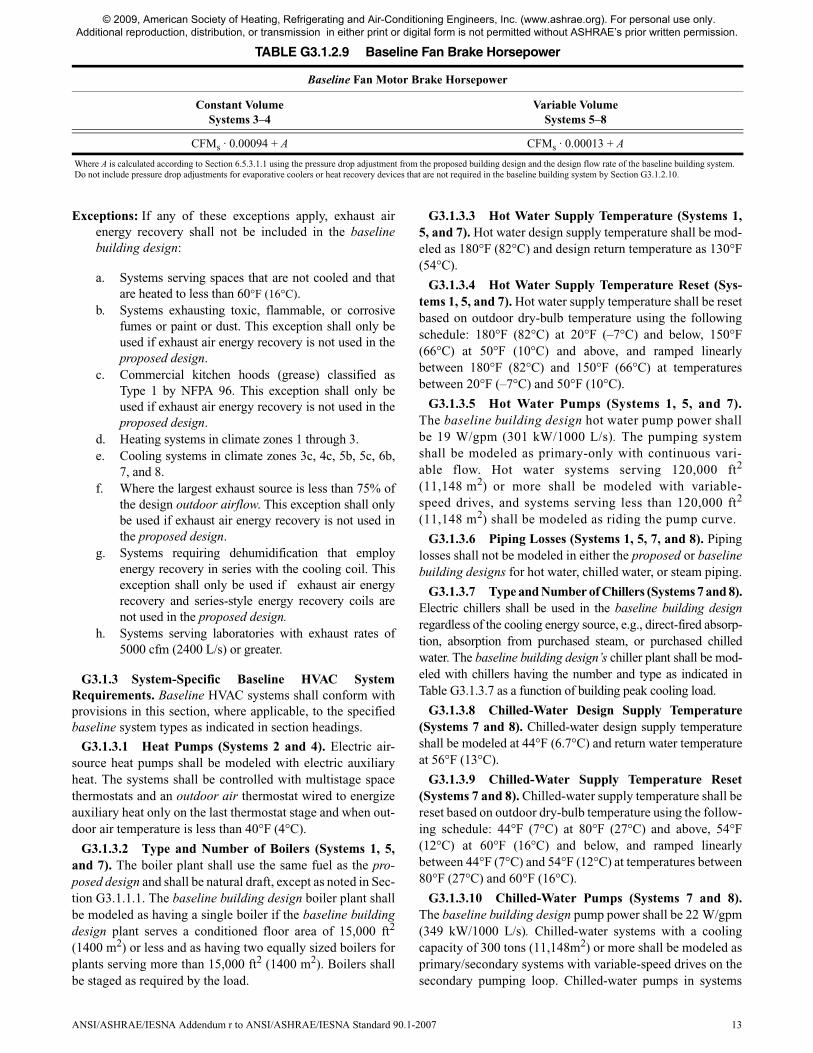
TABLE G3.1.2.9 Baseline Fan Brake Horsepower
Baseline Fan Motor Brake Horsepower
Constant VolumeSystems 3–4
Variable VolumeSystems 5–8
CFMs · 0.00094 + A CFMs · 0.00013 + A
Where A is calculated according to Section 6.5.3.1.1 using the pressure drop adjustment from the proposed building design and the design flow rate of the baseline building system.Do not include pressure drop adjustments for evaporative coolers or heat recovery devices that are not required in the baseline building system by Section G3.1.2.10.
© 2009, American Society of Heating, Refrigerating and Air-Conditioning Engineers, Inc. (www.ashrae.org). For personal use only. Additional reproduction, distribution, or transmission in either print or digital form is not permitted without ASHRAE’s prior written permission.

14 ANSI/ASHRAE/IESNA Addendum r to ANSI/ASHRAE/IESNA Standard 90.1-2007
serving less than 300 tons (11,148m2) cooling capacity shallbe modeled as a primary/secondary systems with secondarypump riding the pump curve.
G3.1.3.11 Heat Rejection (Systems 7 and 8). The heatrejection device shall be an axial fan cooling tower with two-speed fans. Condenser water design supply temperature shall
be 85°F (29°C) or 10°F (5.6°C) approaching design wet-bulbtemperature, whichever is lower, with a design temperaturerise of 10°F (5.6°C). The tower shall be controlled to maintaina 70°F (21°C) leaving water temperature where weather per-mits, floating up to leaving water temperature at design con-ditions. The baseline building design condenser-water pumppower shall be 19 W/gpm (310 kW/1000 L/s). Each chillershall be modeled with separate condenser water and chilled-water pumps interlocked to operate with the associatedchiller.
G3.1.3.12 Supply Air Temperature Reset (Systems 5through 8). The air temperature for cooling shall be resethigher by 5°F (2.3°C) under the minimum cooling load con-ditions.
G3.1.3.13 VAV Minimum Flow Setpoints (Systems 5and 7). Minimum volume setpoints for VAV reheat boxesshall be 0.4 cfm/ft2 (2.15 L/s·m2) of floor area served or theminimum ventilation rate, whichever is larger.
G3.1.3.14 Fan Power (Systems 6 and 8). Fans in parallelVAV fan-powered boxes shall be sized for 50% of the peakdesign primary air (from the VAV air-handling unit) flow rateand shall be modeled with 03.35 W/cfm (0.74 W per L/s) fanpower. Minimum volume setpoints for fan-powered boxesshall be equal to 30% of peak design primary airflow rate orthe rate required to meet the minimum outdoor air ventilationrequirement, whichever is larger. The supply air temperaturesetpoint shall be constant at the design condition.
G3.1.3.15 VAV Fan Part-Load Performance (Systems 5through 8). VAV system supply fans shall have variable-speeddrives, and their part-load performance characteristics shall bemodeled using either Method 1 or Method 2 specified in TableG3.1.3.15.
TABLE G3.1.3.7 Type and Number of Chillers
Building PeakCooling Load
Number and Type of Chiller(s)
≤300 tons(11,148 m2)
1 water-cooled screw chiller
>300 tons(11,148 m2),
<600 tons(22,296 m2)
2 water-cooled screw chillerssized equally
≥<600 tons(22,296 m2)
2 water-cooled centrifugal chillers minimum with chillers added so that no chiller is
larger than 800 tons (2813 kW), all sized equally
TABLE G3.1.3.15 Part-Load Performance for VAV Fan Systems
Method 1—Part-Load Fan Power Data
Fan Part-Load Ratio Fraction of Full-Load Power
0.000.100.200.300.400.50
0.000.030.070.130.210.30
0.600.700.800.901.00
0.410.540.680.831.00
Method 2—Part-Load Fan Power Equation
Pfan = 0.0013 + 0.1470 × PLRfan + 0.9506 × (PLRfan)2 – 0.0998 × (PLRfan)3
where Pfan = fraction of full-load fan power and
PLRfan = fan part-load ratio (current cfm/design cfm).
TABLE G3.2 Power Adjustment Percentages for Automatic Lighting Controls
Automatic Control Device(s)Non-24-h and ≤ 5000 ft2
(460 m2)All Other
1. Programmable timing control 10% 0%
2. Occupancy sensor 15% 10%
3. Occupancy sensor and pro-grammable timing control
15% 10%
Note: These credits are only allowed where the control is not required by Section 9.4. The5000 ft2 (460 m2)condition pertains to the total conditioned floor area of the building.
© 2009, American Society of Heating, Refrigerating and Air-Conditioning Engineers, Inc. (www.ashrae.org). For personal use only. Additional reproduction, distribution, or transmission in either print or digital form is not permitted without ASHRAE’s prior written permission.

POLICY STATEMENT DEFINING ASHRAE’S CONCERNFOR THE ENVIRONMENTAL IMPACT OF ITS ACTIVITIES
ASHRAE is concerned with the impact of its members’ activities on both the indoor and outdoor environment. ASHRAE’smembers will strive to minimize any possible deleterious effect on the indoor and outdoor environment of the systems andcomponents in their responsibility while maximizing the beneficial effects these systems provide, consistent with acceptedstandards and the practical state of the art.
ASHRAE’s short-range goal is to ensure that the systems and components within its scope do not impact the indoor andoutdoor environment to a greater extent than specified by the standards and guidelines as established by itself and otherresponsible bodies.
As an ongoing goal, ASHRAE will, through its Standards Committee and extensive technical committee structure,continue to generate up-to-date standards and guidelines where appropriate and adopt, recommend, and promote those newand revised standards developed by other responsible organizations.
Through its Handbook, appropriate chapters will contain up-to-date standards and design considerations as the material issystematically revised.
ASHRAE will take the lead with respect to dissemination of environmental information of its primary interest and will seekout and disseminate information from other responsible organizations that is pertinent, as guides to updating standards andguidelines.
The effects of the design and selection of equipment and systems will be considered within the scope of the system’sintended use and expected misuse. The disposal of hazardous materials, if any, will also be considered.
ASHRAE’s primary concern for environmental impact will be at the site where equipment within ASHRAE’s scopeoperates. However, energy source selection and the possible environmental impact due to the energy source and energytransportation will be considered where possible. Recommendations concerning energy source selection should be made byits members.