ashida numerical oc/ef type: adr141a adr241a ... i.e. communicable relay) • communication...
TRANSCRIPT

Note: Due to our policy to upgrade our products constantly, we reserve the right to supply products which may vary
Define time
• Programmable operating time in instantaneous element
• Breaker Fail & Trip Circuit Supervision
• Programmable Annunciation Contact
• RS 232 (at front) and RS 485 (at rADR241A i.e. communicable Relay)
• Communication protocol: Proprietary ASCADAprotocol IEC60870-5-103 in model AM102xx (only for ADR241A).
General:
The ADR141A is member of Ashida Numerical Relay family (
and medium switchgear control. The ADR141A is a 3 OC and 1 EF
programmable output to simplify feeder protection wiring. The ADR141A continuously monitors all 3
phases and earth current, through CT connections. The high
through a 12-bit A/D converter. The micro
Amplitude of current signal, and then this value is use for protection and metering function. All
measurement is tuned to fundamental frequency. Each input current is als
display for metering. The Relay is having main three functions 1) Protection 2) Self
Measurement
The Relay can be supplied with different model. It can be either Definite Time or IDMT.
ASHIDA Numerical OC/EF
our products constantly, we reserve the right to supply products which may vary
slightly from that indicated above.
ASHIDA ELECTRONICS PVT LTD. Plot No. A-308, Road No. 21,
Wagle Industrial Estate, Thane (W)-400 604. INDIA.
E-mail: [email protected] Web: www.ashidaelectronics.com
ADR141A_AM10101
Issue: 05 28.06.10
Type: ADR141A
Features:
• 4 Element (3 Phase + EF) current IDMT with instant trip.
• Back - lit LCD display for settings.
• Display of fault current. / Load current.
• Selection of Curve: Six selectable curves (Normal Inverse1 (C1), Normal Inverse2 (C2), Very Inverse (C3), Extremely Inverse (C4), Long Time Inverse (C5) & Definite Time (C6).
• Separate curve selection for phase and EF.
• Design using DSP technology.
• Latching of fault current upfault
• Password protection for setting.
• Site selectable CT secondary
• Relay can be made
Programmable operating time in instantaneous element
Trip Circuit Supervision Function
Programmable Annunciation Contact
(at rear side) Communication Port for remote SCADAADR241A i.e. communicable Relay).
Proprietary ASCADA in model AM101xx and IEC standard open model AM102xx (only for ADR241A).
The ADR141A is member of Ashida Numerical Relay family (Aditya Series) design to meet demand of low
and medium switchgear control. The ADR141A is a 3 OC and 1 EF relay with Instantaneous high set and
programmable output to simplify feeder protection wiring. The ADR141A continuously monitors all 3
and earth current, through CT connections. The high-speed micro-controller samples
. The micro-controller performs powerful Digital Algorithms
Amplitude of current signal, and then this value is use for protection and metering function. All
measurement is tuned to fundamental frequency. Each input current is also displayed on 16 x 2 LCD
display for metering. The Relay is having main three functions 1) Protection 2) Self-Supervision 3)
The Relay can be supplied with different model. It can be either Definite Time or IDMT.
ASHIDA Numerical OC/EF
Protection Relay
our products constantly, we reserve the right to supply products which may vary
Ref.: ADR141A_AM10101
Issue: 05 28.06.10
Type: ADR141A ADR241A
(Communicable) (ADITYA Series) (Preliminary)
4 Element (3 Phase + EF) over current IDMT with instant trip.
lit LCD display for settings.
fault current. / Load
Selection of Curve: Six selectable Normal Inverse1 (C1), Normal
Inverse2 (C2), Very Inverse (C3), Extremely Inverse (C4), Long Time Inverse (C5) &
Separate curve selection for phase
using DSP technology.
Latching of fault current up-to last 5
Password protection for setting.
Site selectable CT secondary
Relay can be made either IDMT or
Communication Port for remote SCADA (only for
and IEC standard open
) design to meet demand of low
relay with Instantaneous high set and
programmable output to simplify feeder protection wiring. The ADR141A continuously monitors all 3
samples this current
Digital Algorithms to find out
Amplitude of current signal, and then this value is use for protection and metering function. All
o displayed on 16 x 2 LCD
Supervision 3)
Note: Due to our policy to upgrade our products constantly, we reserve the right to supply products which may vary
slightly from that indicated above.
ASHIDA ELECTRONICS PVT LTD. Plot No. A-308, Road No. 21,
Wagle Industrial Estate, Thane (W)-400 604. INDIA.
E-mail: [email protected] Web: www.ashidaelectronics.com
Ref.: ADR141A_AM10101
Issue: 05 28.06.10
Type: ADR141A ADR241A
(Communicable) (ADITYA Series) (Preliminary)
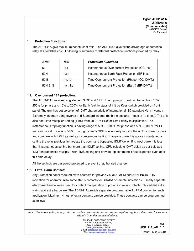
1. Protection Functions:
The ADR141A give maximum benefit/cost ratio. The ADR141A give all the advantage of numerical
relay at affordable cost. Following is summery of different protection functions provided by relay.
ANSI IEC Protection Functions
50 I >> Instantaneous Over current Protection (OC-Inst.)
50N IE>> Instantaneous Earth Fault Protection (EF-Inst.)
50,51 I>t, Ip Time Over current Protection (Phase) (OC-IDMT.)
50N,51N IE>t, IEP Time Over current Protection (Earth) (EF-IDMT.)
1.1. Over current / EF protection:
The ADR141A has 4 sensing element 3 OC and 1 EF. The tripping current can be set from 10% to
250% for phase and 10% to 250% for Earth fault in steps of 1% by Keys switch provided on front
panel. The unit has got selection of IDMT characteristic of international IEC standard Very inverse /
Extremely Inverse / Long Inverse and Standard inverse (both 3.0 sec and 1.3sec at 10 times). The unit
also has Time Multiplier Setting (TMS) from x0.01 to x1.0 for IDMT delay multiplication. The
instantaneous tripping function is having range of 50% - 3000% for phase and 50% - 3000% for EF
and can be set in steps of 50%. The high speeds CPU continuously monitor the all four current inputs
and compare with IDMT as well as instantaneous setting. If anyone current is above instantaneous
setting the relay provides immediate trip command bypassing IDMT delay. If is input current is less
than instantaneous setting but more than IDMT setting, CPU calculate IDMT delay as per selected
IDMT characteristic multiply it with TMS setting and provide trip command if fault is persist even after
this time delay.
All the settings are password protected to prevent unauthorised change.
1.2. Extra Alarm Contact:
Any Protection panel required extra contacts for provide visual ALARM and ANNUNCIATION
indication for operator. Also some status contacts for SCADA or remote indications. Usually separate
electromechanical relay used for contact multiplication of protection relay contacts. This added extra
wiring and extra hardware. The ADR141A provide separate programmable ALARM contact for such
application. Maximum 4 nos. of extra contacts can be provided. These contacts can be programmed
as follows

Note: Due to our policy to upgrade our products constantly, we reserve the right to supply products which may vary
slightly from that indicated above.
ASHIDA ELECTRONICS PVT LTD. Plot No. A-308, Road No. 21,
Wagle Industrial Estate, Thane (W)-400 604. INDIA.
E-mail: [email protected] Web: www.ashidaelectronics.com
Ref.: ADR141A_AM10101
Issue: 05 28.06.10
Type: ADR141A ADR241A
(Communicable) (ADITYA Series) (Preliminary)
ANN. TYPE 1 ANN. TYPE 2 ANN. TYPE 3 ANN. TYPE 4
RELAY 1 OC1 OC HF HF COM. ALARM
RELAY 2 OC2 OC IDMT IDMT PROTH.
RELAY 3 OC3 EF HF PHASE PHASE
RELAY 4 EF EF IDMT EF EF
2. Supervision Function:
2.1 Self-supervision:
The continuously keeping track on its internal hardware and the movement it detect any failure of any
component, it give message on LCD display, This feature is very useful to give pre information to avoid
any mall - operation. In such situation it use some default setting and remain in protection mode.
3. Measurement Function:
In normal condition this display shows all settings. Via keyboard the display can be program to show the
actual current flowing through the relay. If current excesses set value the relay gives trip command.
The type of fault is displayed on LCD display. During the fault condition the relay measure the fault
current and store in non-volatile memory. The fault current can be read via keyboard on LCD
display Last 5 fault values along with tripping counter can be view via key-board. All settings are
save in electrically erasable read only memory and remain.
4. Breaker Fail Function (BF or LBB)
Normally after tripping current should be come Zero within 100 – 200ms time depend upon type of fault
and breaker mechanism. After Fault Relay start one internal timer (settable from 0.05s to 0.8 s) If fault
is not cleared during this time then relay declare as Breaker fail (LBB function)
5. Status :
Status input S1 and S2 are general purpose for SCADA application and S3 and S4 are dedicated for
CB NC and NO used for trip circuit supervision.

Note: Due to our policy to upgrade our products constantly, we reserve the right to supply products which may vary
slightly from that indicated above.
ASHIDA ELECTRONICS PVT LTD. Plot No. A-308, Road No. 21,
Wagle Industrial Estate, Thane (W)-400 604. INDIA.
E-mail: [email protected] Web: www.ashidaelectronics.com
Ref.: ADR141A_AM10101
Issue: 05 28.06.10
Type: ADR141A ADR241A
(Communicable) (ADITYA Series) (Preliminary)
Ordering Information:
The relay is available with nos. of different option. The option is specified by model no. It is user
responsibility to specify correct model no. while ordering.
While Order ing Specify the fo l lowing Information for ADR141A Re lay
Order ing information:
A D R 1 4 1 A - A M - X X X - X X - X - X - X X - X
Example
ADR141A – AM-101-01-3-0-2-0
Type: ADR141A
Back Terminal Layout : With 4 Programmable extra contacts, Selectable CT TSS Logic.
Cabinet Type: CSA-150 non Drawout
Auxi l i ary Supply: 77-250Vdc
CT sec: 1/5 Amp.
AM XXX X X
3OC + 1EF Relays
101 ( with ASCADA Protocol for communication)
01 Relay with site selectable CTs, Trip circuit supervision and breaker fail function. 4 extra Ann. Contacts and 4 optically isolated status inputs ( 2nos for TSS )
CSA – 150 3
02 Relay with site selectable CTs in Draw out cabinet. CSA – 150D 3
102 ( with IEC60870-5-103 Protocol for communication)
01 Relay with site selectable CTs, Trip circuit supervision and breaker fail function. 4 extra Ann. Contacts and 4 optically isolated status inputs ( 2nos for TSS )
CSA – 150 3
02 Relay with site selectable CTs in Draw out cabinet. CSA – 150D 3
Note: communication protocols are only applicable for ADR241A relay models.
D e f i n i t i o n o f M o d e l N o o f A d i t y a S e r i e s o f R e l a y s
A M X X X – X X – X – X – X X – X
Auxiliary Supply 01 = 18 – 52 V dc 02 = 77 – 250 V dc 03 = 110 VAC 04 = 230 VAC 05 = 60 V dc 06 = 18 - 250 V dc
Reserved for Future Use
PT Secondary
0
CT Secondary 1 = 1 Amp. 2 = 5 Amp. 3 = 1 Amp. / 5 Amp. Selectable

Note: Due to our policy to upgrade our products constantly, we reserve the right to supply products which may vary
slightly from that indicated above.
ASHIDA ELECTRONICS PVT LTD. Plot No. A-308, Road No. 21,
Wagle Industrial Estate, Thane (W)-400 604. INDIA.
E-mail: [email protected] Web: www.ashidaelectronics.com
Ref.: ADR141A_AM10101
Issue: 05 28.06.10
Type: ADR141A ADR241A
(Communicable) (ADITYA Series) (Preliminary)
Technical Specifications:
Sr. No.
Specification Particulars
I. For Model AM101xx
[ 3OC + 1EF relay ]
Inputs : Suitable for CT secondary 1.0 Amp or 5.0 Amp. (Selectable)
Protection Relay Setting Range
: Setting For phase 10% - 250 %
For EF 10% - 250%
: Operating Time Normal Inverse 1 (C1)
Normal Inverse 2 (C2)
Very Inverse (C3)
Extremely Inverse (C4)
Long Time Inverse (C5)
Definite Tme (C6) 00(Inst) – 99.9Sec
: Inst. Setting For phase 50% - 3000%. or bypass In steps of 50%
For EF 50% - 3000% or bypass In steps of 50%
: Inst Operating Time Inst = < 30ms and additional adjustable software delay of 00 – 2.0Sec in steps of 10ms.
Output contacts
: Model AM10101xxxxx & AM10201xxxxx
1) 2 NO Trip duty contact for Alarm and Trip
2) 4 NO ANN. Duty contacts ( Programmable)
: Model AM10102xxxxx & AM10202xxxxx
2 NO Trip duty contact for Alarm and Trip
II. Pickup Current : Within 1.1 times of set current value.
III. Resetting Current : 90% of set value.
IV. Time Accuracy : Within class 5 As per IS: 3231.
V. Burden on CTs : Less than 0.2VA.
VI. Aux. Supply : 18 – 52VDC or 77 – 250VDC. To be specified while ordering.
VII. Burden on Aux. Supply : Less than 10VA on any supply.
VIII. Contact Rating Trip Duty : Make and carry for 3sec. – 7500VA with max. 30A & 660VAC/DC
: Make and carry for continuous – 1250VA with max. 5A & 660VAC/DC
: Break AC – 1250 VA DC – 100 W resistive 50W inductive.
IX. Operational Indicators (Flags)
ON / Error : Green LED indicates Relay OK
: Red LED indicates Problem in relay Hardware.

Note: Due to our policy to upgrade our products constantly, we reserve the right to supply products which may vary
slightly from that indicated above.
ASHIDA ELECTRONICS PVT LTD. Plot No. A-308, Road No. 21,
Wagle Industrial Estate, Thane (W)-400 604. INDIA.
E-mail: [email protected] Web: www.ashidaelectronics.com
Ref.: ADR141A_AM10101
Issue: 05 28.06.10
Type: ADR141A ADR241A
(Communicable) (ADITYA Series) (Preliminary)
PKP / HF : Green LED indicates relay Pickup.
: Red LED indicates relay operated at HF.
OC Fault / EF Fault : Green LED indicates the relay tripped by OC, Hand Reset (HR) Type
: Red LED indicates the relay tripped by EF, Hand Reset (HR) Type
TRIP / BF : Green LED Indicates that Trip pulse is being executed. SR type when TRIP contact selected as SR and HR type when TRIP contact selected as
HR. When BYPASS P.B. is pressed, actual trip is not executed.
: Red LED indicates BF operated. SR type when BF contact selected as SR and HR type when BF contact selected as HR.
X. Thermal Withstand Capacity : x40 times the normal current for 3sec.
: x2 Continuous
XI. High Voltage Test
: IEC 60255-5
: Except DC Voltage – 2.0 kV (RMS), 50Hz
: Only DC voltage - 2.8 kV DC
: Between Open contact of TRIP / CLOSE 1.5kV (RSM) 50Hz
: Between Open contact of ALARM – 1kV (RSM) 50Hz
XII. Impulse Voltage Test (all circuit class – III)
: IEC60255-5
: 5kV (peak) 1.2 / 50us, 0.5 J, 3 positive and 3 negative impulse at interval of 5 sec
XIII. High Frequency test : IEC 60255-22-1, Class III
: 2.5 kV (peak) 1MHz , τ = 15µs 400 surges / s duration 2 s
XIV. Electro static Discharge : IEC 60255-22-2 Class III and IEC 61000-4-2 class III
: 4kV/6kV contact discharge, 8kV air discharge, both polarities 150pF, Ri
330 Ω
XV. Irradiation with radio frequency field, pulse-
modulated,
: IEC 60255-22-3 and IEC 61000-4-2 class III
: 10V/m; 80 to 1000MHz; 80%; 1kHz AM
XVI. Fast transient interference/bursts
: IEC 60255-22-3 and IEC 61000-4-3, class III
: 4kV; 5/50ns; 5kHz burst duration = 15ms;
: Repetition rate 300ms; Both polarities; Ri = 50Ω; duration 1 min.
XVII. Shock Test : IEC 60255-21-2 class 1
: Semi-Sinusoidal
: 5g acceleration, duration 11ms,
: Each 3 shocks in both direction of the 3 axes
XVIII. Vibration Test : IEC 60255-21-1 class 1 / IEC 60068-2-6
: Sinusoidal 10 to 60Hz ±0.035 mm
: Amplitude, 60 to 150Hz, 0.5g acceleration
: Sweep rate 1 octave/min; 20 cycle in 3 orthogonal
XIX. Seismic Test : IEC 60255-21-3

Note: Due to our policy to upgrade our products constantly, we reserve the right to supply products which may vary
slightly from that indicated above.
ASHIDA ELECTRONICS PVT LTD. Plot No. A-308, Road No. 21,
Wagle Industrial Estate, Thane (W)-400 604. INDIA.
E-mail: [email protected] Web: www.ashidaelectronics.com
Ref.: ADR141A_AM10101
Issue: 05 28.06.10
Type: ADR141A ADR241A
(Communicable) (ADITYA Series) (Preliminary)
: In single axis sine sweep in X-axis
sweep (@a sweep rate of 1 octave/minute) vibration in the frequency range (5-40 Hz) at amplitude of 3.5mm or 1.0gn (whichever is less)
: In single axis sine sweep in Y-axis
- weep (@a sweep rate of 1 octave/minute) vibration in the frequency range (5-40 Hz) at amplitude of 1.5mm or 0.5gn (whichever is less)
XX. Bump Test : IEC 60255-21-2 Class-1
: 1000 bumps of 10gn peak acceleration and 16ms pulse duration in each of the two opposite direction per axis as per IEC60255-21-2 class 1 No. of
axes . 3.
XXI. Shock Withstand : IEC 60255-21-2 Clas-1
: 3 shocks of 15gn peak acceleration and 11ms pulse in each of two opposite direction . No. of axis : 3
XXII. Shock Response Test : IEC 60255-21-2 Clas-1
: 3 shocks of 1gn peak acceleration and 11ms pulse in each of two opposite direction . No. of axis : 3
XXIII. Vibration Endurance Test
: IEC60255-21-1
20-sweeps (@ a sweep rate of 1octave / minutes) vibration in the frequency range (10-150Hz) at 1 gn (9,8m/s2) acceleration in each of the 3 mutually
perpendicular axes
XXIV. Environmental withstand (cold, Dry heat & steady
state Damp Heat)
: IEC60068-2
Cold – 2 hours operational condition at –(40 +/- 3) deg C as per IEC60068-2-1
Dry – 2 Hours dry heat operational condition at(55+/2 2 deg. C as per IEC60068-2-2
Steady state damp heat - 2 hours steady sate damp heat operational condition at temperature at (55 +/- 2) deg. C & humidity 95% RH as per
IEC60068-2-78
XXV. Drawing References : For Cabinet Type CSA -150 - MAC00101
: For Operating Characteristics
C1 - APR02201
C2 - APR01801
C3 - APR05101
C4 - APR05201
C5 - APR05301
: For Electrical Connection
3OC + 1EF AM10101 - APR06804_2
• Datasheet Change Log for ADR141A

Note: Due to our policy to upgrade our products constantly, we reserve the right to supply products which may vary
slightly from that indicated above.
ASHIDA ELECTRONICS PVT LTD. Plot No. A-308, Road No. 21,
Wagle Industrial Estate, Thane (W)-400 604. INDIA.
E-mail: [email protected] Web: www.ashidaelectronics.com
Ref.: ADR141A_AM10101
Issue: 05 28.06.10
Type: ADR141A ADR241A
(Communicable) (ADITYA Series) (Preliminary)
Issue No. (Revis
ion)
Date Description /Changes
01 28.08.09 Original Revision
02 01.11.09 Communicable Model ADR241A added
03 01.12.09 Photograph of the relay Modified
04 09.12.09 Settings Changed