asf mamm processing sys · pdf filerelated documentation ... which is a marked difference...
TRANSCRIPT

Alaska SAR Facility’sAlaska SAR Facility’sAlaska SAR Facility’sAlaska SAR Facility’s
MAMM Processing SystemMAMM Processing SystemMAMM Processing SystemMAMM Processing System
August 2001

ASF-NUMBER 6/14/2007 II
Signature Page
Prepared by: ____________________________________________date: ____________ Dr. Nettie LaBelle-Hamer ASF Science Center Manager
Reviewed by: ____________________________________________date: ____________ Dr. Ken Jezek Byrd Polar Research Center Scientist and PI for RAMP
____________________________________________date: ____________ Richard Marlin ASF Principal Systems Engineer
____________________________________________date: ____________ Marcia Boyette ASF Development Engineer
____________________________________________date: ____________ Rory O’Neill ASF USO Science Consultant
____________________________________________date: ____________ Carel Lane ASF Operations Center Manager
____________________________________________date: ____________ Jamie Marschner ASF Engineering Center Manager
____________________________________________date: ____________ Jay Cable ASF Development Engineer
Approved by: ____________________________________________date: ____________ Dr. Verne Kaupp
ASF Director

ASF-NUMBER 6/14/2007 III
Document: MAMM Processing System Description
Original Date: August 2001
ISSUE DATE PAGES AFFECTED APPROVAL
Original 08/2001 All pages affected N/A

ASF-NUMBER 6/14/2007 IV
Table of Contents
Signature Page............................................................................................................................... ii
Document: MAMM Processing System Description ............................................................... iii
Table of Contents ...........................................................................................................................iv
Introduction ................................................................................................................................... 1
Related Documentation ................................................................................................................ 2
Design Approach and tradeoffs ................................................................................................... 3
Overview ................................................................................................................................................... 3
Production Expectations and Limitations ........................................................................................... 4
New Development.................................................................................................................................... 5
Architectural Design Description ................................................................................................ 6
MAMM L0 and L1 Queue Management ............................................................................................ 6 L0 Production Planning .......................................................................................................................................... 6 L1 Production Planning .......................................................................................................................................... 7
MAMM Production Database .............................................................................................................. 7
QC Analysis tool ...................................................................................................................................... 8 List of PAR File Fields Used in Calculations by QC_PAR program .................................................................. 9 Binary Fields Checked by QC_PAR program .................................................................................................... 11 Checks removed from QC algorithm .................................................................................................................. 11
LZP Post Production Processor .......................................................................................................... 11
MAMM chop/par file ingest utility ..................................................................................................... 16
MAMM L1 Processor ........................................................................................................................... 17 Steps in L1 processing: ......................................................................................................................................... 18
L0 Electronic Queue ............................................................................................................................. 23
External Interface Design .......................................................................................................... 24
Interface with OSU ............................................................................................................................... 24 Export metadata files ............................................................................................................................................ 24 Import chop files ................................................................................................................................................... 24 Export data products ............................................................................................................................................. 24
Requirements Allocation and Tracing ...................................................................................... 25
Production and Interface Requirements ........................................................................................... 25
MAMM Specific Processing Parameters........................................................................................... 26
Appendix A: L0 STF Production Design ................................................................................. 27
Appendix B: L1 Production Design........................................................................................... 28
Appendix C: DLT Production Design ....................................................................................... 29

ASF-NUMBER 6/14/2007 1
Introduction
The RADARSAT Antarctic Mapping Project (RAMP) is a NASA Pathfinder data project involving collaboration between NASA and the Canadian Space Agency (CSA). The project comprises two mapping missions of Antarctica using the RADARSAT satellite. Each mapping mission has two phases: the data acquisition phase and the processing phase. The data acquisition phase for the first Antarctic Mapping Mission (AMM-1) was successfully completed in October 1997. In order to collect the data over the South Pole, CSA maneuvered their satellite into a left-looking acquisition mode. ASF’s portion of the processing phase for AMM-1 was completed one year later, October 1998. Byrd Polar Research Center further processed the data into mosaic tiles that are distributed in various resolutions by ASF.
The data for the second mapping mission, Modified Antarctic Mapping Mission (MAMM), was collected in September-November, 2000. The satellite remained in the right-looking mode during the acquisition of the MAMM, which is a marked difference between the two mappings.
Without the maneuver of the satellite, the acquisitions were limited to regions north of about –80 degrees latitude. The objectives of the mission were also modified from the first mission in that velocity field measurements became of primary importance. The duration of the mission was accordingly extended to cover three cycles, as opposed to the 18-day AMM-1, in order to achieve interferometric pairs.
During the MAMM acquisition phase, it was planned to acquire as much data real time to McMurdo as possible. Once McMurdo started experiencing difficulty in the second cycle, ASF became the primary reception facility with acquisitions close in numbers to Prince Albert and Gatineau. The OBR data downlinked at ASF was scanned immediately into the ASF catalog. Data from all the other ground stations were transported as soon as possible to ASF and scanned on delivery.
The MAMM data were successfully collected and are currently archived as signal data at the Alaska SAR Facility. ASF will be processing all the signal data collected for MAMM to single look complex (SLC) products to be delivered to Ohio State University (OSU) for further processing. The final products will be distributed through the ASF. In order to process the MAMM data, a specialized processing system was designed and built at ASF. This MAMM processing system is the focus of this document.

ASF-NUMBER 6/14/2007 2
Related Documentation
1. Antarctic Mapping Mission – 2, RADARSAT-1 Antarctic Mapping Project, Science Requirements Document, June 12, 2000, updated April 5, 2001, Byrd Polar Research Center.
2. ASF-00-OPS001-1.0 Modified Antarctic Mapping Mission (MAMM) Mission Operations Plan, June 22, 2000.
3. ASF-00-REQ001-2.13 Modified Antarctic Mapping Mission, ASF Functional Requirements Document, April 20, 2000.
4. ASF-00-CAL120-1.0 Alaska SAR Facility, RADARSAT Modified Antarctic Mapping Mission Calibration Plan.
5. RADARSAT Antarctic Mapping System 2 (RAMS-2), Functional Requirements Document, Version 2.2, April 26, 2000, Vexcel Corporation.
6. ASF-01-OPS-122-1.0 Modified Antarctic Mapping Mission Operations Plan: The ASF Processing Phase, April 2001.
7. OSU/Vexcel AMM-2 Processing Plan Phase1, April 5, 2001, Byrd Polar Research Center.
ASF-NUMBER 6/14/2007 3
Design Approach and tradeoffs
Overview
The raw signal data archived and cataloged at ASF for the MAMM mission will be processed first to Level-0 data format and then to Level-1 data format, specifically to single-look complex (SLC) format. The processing system to be used for this processing has been designed specifically for the MAMM project. Although portions of the MAMM processing system will be used by ASF for general user data production, some portions are exclusive to this project.
The Level-0 processor used for the MAMM processing is the Level-0 Processor (LZP) software designed by Vexcel Corporation. ASF will be using version 2.28.6 of the LZP code installed on an SGI O2100 in the ASF Operations Center. In the course of processing, it may be decided to add either more LZP strings or more hardware platforms or both to meet schedule. This decision is the responsibility of ASF on the recommendation of the ASF MAMM Project Manager.
The Level-1 processor to be used for the MAMM processing is the Focus software designed by Vexcel Corporation. ASF will be using version 2.28.5 of the Focus code with the radar delay time set to an empirically derived value specific for MAMM production. This code is installed on an SGI O2100 in the ASF Operations Center. Whether the Focus software and the LZP software for the MAMM processing are on the same SGI O2100 or separate ones is the responsibility of ASF.
The glue code which allows for data flow between the processors, the databases managing the processing information and all the staging hardware and software have been built and/or implemented by ASF Development Engineers with or without the aide of contracted developers. There are also numerous scripts, GUI’s, and tools necessary for the processing system to function. ASF is responsible for all of these as well. The design concepts for the system are shown in the appendices. Appendix A shows the data flow design for the Level 0 production while Appendix B and C show the data flow design for Level 1 production and tape write out, respectively.
Some common terminology will be needed for the cross-company communication concerning processing to be clear and concise. For instance, downlinks and datatakes are distinct identifiers for data bits. Either the downlink orbit or the datatake orbit can be used to identify the SAR signal data archived at ASF. A downlink is defined as the data streaming from the satellite to the ground station from lock on to lock off. A downlink can consist of real time data, which is data captured as the satellite flies overhead, or On Board Recorder (OBR) data, which is data that was previously recorded, or both. A datatake is the data recorded from SAR on to SAR off either in real time or on the OBR. One downlink can contain many datatakes—some real time and some OBR.
When processing data, the datatake orbit is most often used as it described when the data was acquired and, when used with the sequence number, is a unique identifier. When downlinking data, the downlink orbit is used to identify when the data was received. The Vexcel documentation often uses the segment in place of datatake. For simplicity, we will use only “datatake” here.

ASF-NUMBER 6/14/2007 4
The term granule is utilized throughout this document and should be interpreted to indicate a set of files (data, metadata, and auxiliary) sharing the same basename and differentiated by their file extension (basename.extension). The basename itself may contain period-delimited values (e.g., R126822FN1S68W115003.000.extension)
In order to process the approximately 2500 MAMM datatakes from signal data to Level-0, ASF will go through two general steps. First, the ASF Production Planners do planning of the production in User Services. Second, the ASF Operators do the actual processing of the data in the Operations Center. Quality control checks are run on both the Level-0 binary data and metadata prior to continuation.
Once the raw signal data has been processed to Level-0 data, the preparation to further process to SLC begins. The metadata and quick-look, or tif, files are placed on the ftp site by the LZP post processor. The ASF Quality Control (QC) Engineer reviews the file list to ensure failed or duplicated files are not passed to the OSU Operator. Once the OSU Operator receives an email from the ASF QC Engineer verifying the tar files have been staged, she pulls these files to OSU via ftp. The OSU Operator performs a check for a Doppler ambiguity error and corrects the par file, if necessary. The tif files will be used in conjunction with the par files to generate chop files. These chop files will contain the frame-sizing information and the elevation correction information needed to process the SLC products.
The OSU Operator will stage the newest version of the par file and the newly generated chop files to the ftp site. The Ingest Utility will pull the new par and chop files from the ftp site and ingests them in the proper directory on the silo. An email will be sent to the ASF Production Planners and Data Quality Team to notify them the files are accessible. Once available, the chop and par files will be used to process the data to Level-1.
The completed Level-1 products are cataloged in the ASF IMS and are available for search and order through the EDG. Since these products are specific to the MAMM project, the valids used are dynamic rather than static. The OSU Operator can search and place the desired orders. Once the order is placed, the status of the granule is updated to “in media queue” and the products are written onto DLT tapes. These Level-1 product tapes are then shipped via DHL to OSU.
Production Expectations and Limitations
MAMM production will occur in two overlapping phases utilizing 3 or more SGI Origin 2100 multi-CPU servers. All MAMM Origin servers will receive SAR telemetry via one Sun SOLARIS CPU hosting a Level Zero Controller (L0C). Data Path switch, clock, and HDDT recorder assignments will be specified in a document external to this one.
Staffing limitations aside, MAMM production will be conducted along side existing production activities without resource conflicts. The two phases of MAMM production are telemetry-to-L0_STF and follow on L0_STF-to-L1_SLC. Each datatake will result in a single L0 STF granule (phase one production) and there are approximately 2427 RADARSAT-1 datatakes of varying beam modes in the MAMM dataset (representing 4463 minutes of SAR instrument on-time). At 1 GB/minute, that’s nominally 4.4 TB of SAR L0 data, and at a 2.5:1 inflation would yield 11 TB of SAR L1 single look complex data in CEOS format.

ASF-NUMBER 6/14/2007 5
The burden of specifying how each datatake is to be processed into overlapping, variable-length scenes is being handled by the MAMM Project Team at Ohio State University led by Dr. Ken Jezek, Byrd Polar Research Institute. Included within the scene definition file for each L0 STF granule (basename.chop) are L1 processing parameters such as scene elevation correction and processor bandwidth. The OSU Team will be conveying Doppler ambiguity adjustments for each datatake, where necessary, through a modified L0 STF granule parameter file (basename.par). In addition, the OSU Team is responsible for providing unique granule basenames for all SAR L1 SLC (single look complex) granules generated, where a new version number will be assigned along with adjustments to any L1 processing parameter value.
New Development
In order to accommodate the needs of the RAMP mission, new development beyond the processors were designed, developed, tested and implemented at ASF. These new pieces are listed below and described in greater detail in the next section.
1. MAMM L0 and L1 Queue Management
2. MAMM Production Database
3. QC Analysis Tool
4. LZP Post Production Processor
5. MAMM chop/par file ingest Utility
6. MAMM L1 Processor
7. L0 Electronic Queue

ASF-NUMBER 6/14/2007 6
Architectural Design Description
The diagram in Appendix A is an overview of the design of the L0 production portion of the MAMM processing. The diagrams in Appendices B and C are the overviews of the design of the L1 production and the tape production portions of MAMM processing, respectively.
MAMM L0 and L1 Queue Management
L0 Production Planning
Planning the MAMM Datatakes
A MAMM specific script will identify and list all MAMM Scan Results Files (SRFs). MAMM datatake I.D.’s, parsed from the SRFs, will be fed into the L0_plan_tool script. The L0_plan_tool script was created due to the large volume of MAMM L0 swaths. Prior to the existence of this tool, the Production Planner performed the tasks manually. The L0_plan_tool script extracts information from the Scan Results File and outputs buffered tape addresses, media I.D., and other planning informationinto a tab-delimited format. This information is put into a spreadsheet.
MAMM datatake tape addresses, as stated above, come from the SRFs which in themselves are generated by the Raw Data Scanner (RDS). The L0_plan_tool script buffers the addresses for Sony tapes from the SRFs by subtracting 300 tape units from the start address, and adding 300 tape units to the stop address. This buffering size was calculated empirically by APD as the best balance between processing unwanted data, and compensating for any variations in the data’s tape-location as determined by the RDS.
Creating the Order
After discussion and experimentation with grouping datatakes by tape into jobs, to meet the project’s processing goals the MAMM datatakes will be planned and processed individually. The ASF Production Planner will supply the OSU Operator with the MAMM datatake list. The OSU Operator will create an order by supplying the ASF Production Planner with a list of datatakes. For the best support of the science goals of the Principal Investigator, this list will be ordered by geographic region.
Loading the MAMM database
A database has been created specifically for tracking progress and trouble shooting the MAMM production at ASF. ASF Production Planners will load two of the MAMM database tables, mamm_datatakes and mamm_l0_jobs, prior to processing. Automatic updating of some fields of the database occurs after processing. The ASF Production Planner will manually update the MAMM database when necessary.
Queuing
Within each OSU order, the ASF Production Planner will arrange the processing sequence of the datatakes for greatest efficiency. That is, datatakes will be sorted by media id, before being presented to the Operators.

ASF-NUMBER 6/14/2007 7
The ASF Production Planner will create a production queue by querying the database for “NULL” status granules of the desired beam and geographic location. The information returned from this search will be formatted and loaded into the L0 electronic queue.
Operators will run jobs from the electronic queue. Operators will select the recorder and processor for each job from a pick list, and type in their initials. No further data entry is required.
L1 Production Planning
The MAMM L1 production queue will reside within the MAMM production database and thus be continuously available to the MAMM L1 Processor string(s) via crontab queries to the database (mamm_datatakes.datatake_status = ‘READY_FOR_L-1_PROCESSING’). The MAMM L1 Processor(s) will be permitted to poll the production database at will and depend on the silo robot and IMS to provide L1 job input data.
We will be relying on the dependability (up time) of the IMS/DADS, by hosting the MAMM Production Database there, as well as the silo.
Alternatively, a L1 production queue text file containing a list of datatake ids or STF Granule basenames, one per line, will be staged to each MAMM L1 Processor host. In this mode, Operations staff will start each MAMM L1 Processor using a UNIX command line invocation, including the production queue filename & its path as part of that command.
The Production Planner will receive new chop and par file availability notification from the Ingest Utility. The Production Planner will query the MAMM database in order to generate the production queue for the MAMM Level-1 processor. The production queue will be a list of orders with the Level-0 data and all required metadata available in the silo.
The Level-1 processing will proceed in an as ready fashion. The planning at the Level-0 stage will predetermine the approximate, but not necessarily the exact, sequence for Level-1 processing.
MAMM Production Database
The MAMM Production Database consists of four separate tables, to be specified outside this document :
1. mamm_datatakes
2. mamm_slc_products
3. mamm_l0_jobs
4. mamm_stf_granules
The list of MAMM datatakes downlinked to the four participating ground stations is known, however, this number represents an upper bound for the MAMM telemetry expected to be processed by the ASF DAAC. There is no guarantee that all McMurdo, Prince Albert and Gatineau telemetry will arrive in Fairbanks, Alaska.

ASF-NUMBER 6/14/2007 8
Prior to the start of MAMM L0 Production the first table noted above (mamm_datatakes) will be loaded with datatake ids, one record per datatake, representing the 2400+ MAMM datatakes listed in the Track Team DataBase as successfully downlinked to a ground station. In addition, this table will serve as the process status repository for all MAMM L0 Processors.
The second table (mamm_slc_products) was populated initially by the MAMM File Ingest Utility when it parses a copy of each chop file received from OSU. Included with the variable length scene definitions for the L0 STF granule (datatake) are the L1 SLC granule basenames corresponding to each scene (output_slc_filename). Therefore, prior to the start of MAMM L1 processing database records for each output L1 SLC granule will be accessible by the L1 processor enabling a simple production quality control measure. In addition, this table will serve as the process status repository for all MAMM L1 Processors, and is expected to contain one record per variable-length scene generated (10,000 ≤ # records ≤ 30,000, dependent upon L1 reprocessing).
The third table noted above (mamm_l0_jobs) contains the L0 job production queue as it is built. The OSU Project Team has indicated a beam mode. The fourth table (mamm_stf_granules) contains L0 status and the ASF/OSU par and chop file status.
QC Analysis tool
The Level-Zero Processing System (LOPS) quality control (QC) algorithm was designed to provide a thorough quality assessment of Sky Telemetry Format (STF) L0 data being produced at the Alaska SAR Facility (ASF). The impetus for the development is to verify that only valid, usable signal data is migrated to the ASF archives by the Level-0 Archive Migration (LOAM). The algorithm will be separated into two logical sections - metadata and binary analysis.
The LOPS QC algorithm has undergone several modifications to support quality testing for the MAMM L0 production system. First, the QC function was converted into a standalone QC program called qc_par. The biggest change was modification of the front end to use the PAR file instead of an ODL block. However, since the input ODL block is derived from the PAR file, this proved to be a nearly one-to-one mapping.
Metadata checks will provide an assessment of important STF PAR file fields. Satellite/platform specific parameters will be validated for correctness, reasonableness, and/or consistency. This will include beam specific and viewing geometry parameters. Testing the validity of the state vectors and Doppler information, verification of slant ranges, and re-calculation of geolocations using the actual values from the PAR file will verify Geolocation information. All of these checks that are applicable will be performed not only on the global metadata, but also on each location block in the PAR file.
Decoding the telemetry headers and checking the resulting values will provide an assessment of the counters and auxiliary headers in the signal data. Sync codes will be checked and used as an estimate of the bit error rate of the data. Counters will be verified by anticipating expected value changes. Large portions of the binary auxiliary headers will also be checked for correctness, reasonableness, and/or consistency.
To correctly do this, the PAR file missing block information was to be utilized, and thus an implicit check of the missing data blocks will be enacted. Because the number of frames reported in the missing data blocks was found to be an estimate, using it was unreliable.

ASF-NUMBER 6/14/2007 9
Therefore, the missing data structure was changed to contain and index by the start line instead of the start frame.
Due to several unexpected binary anomalies, the algorithm was modified to rely on the index file as an additional input. This provides the ability to implicitly check this file. In addition, it allowed for a new error type to be discovered which has been labeled as a false Aux frame. A false Aux frame is one in which the binary header designates an Aux frame, but the index file does not. A count of these errors may be found in the ODL output object RSAT1_FRAME_CHECK.AUX_DATA_CHECK.
The QC program will operate at one of two levels of assessment – standard or detailed. The standard operation will check a user configurable percentage of the binary data. The detailed assessment will check 100% of the binary data. In either case, the same metadata will be checked.
The QC program will return a status of GOOD, MODERATE, BAD, or ERROR. It will return a GOOD status if all checks are within their minimal tolerance value. It will return a MODERATE status if one or more parameters exceed their minimal tolerance value but no critical parameters exceed their moderate tolerance. It will return a BAD status if one or more critical parameters have exceeded its moderate tolerance value or there is a detected mismatch with a critical binary check. A status of ERROR will be returned if the QC Algorithm encounters an error which is beyond its control. This would be related to lack of required input data, faulty input data, or resource constraints in which the QC Algorithm could not complete QC evaluation.
The QC program will create two output files. The QC log file will provide detailed information regarding the individual checks that did not pass minimal tolerance along with other informational messages. The output to the log will be configurable to contain from minimally to extremely verbose output. The QC ODL file will contain an ODL block structure containing measured differences for metadata checks that do not pass within minimal tolerance and a count of errors for binary checks.
To overcome some of the checks that were failing due to the Fine Beam OBR/RLT problem, geolocation and slant range tests were modified to use the PAR file nr_of_samples rather than a binary decoded value.
Following is a complete list of PAR file fields that are used in calculations by the QC program. The majority of these fields are checked directly. However, some of them are just used in calculations of other fields. Either way, if any of them contain detectable errors, the QC program will produce a related message.
List of PAR File Fields Used in Calculations by QC_PAR program
Prep_block number_bytes number_lines satellite instrument number_of_beams missing_lines first_date last_date tce_UTC tce_satellite

ASF-NUMBER 6/14/2007 10
tce_corr nominal_look_angle number_range_samples swath_velocity GHA angle date orbitNr clock_angle sensor beam beam_name nr_of_samples carrier_freq sampling_freq PRF chirp_rate pulse_length incidence_angle DopplerCentroidParameters reference_first_dimension reference_second_dimension reference_range reference_date ambiguity_number ephemeris sv_block NrSV state_vector x y z xv yv zv Date location_blocks frame_nr start_byte sattelite_clock line_date first_pixel_ll last_pixel_ll SWST_code SWST range_gate near_range far_range DopplerPolynomial reference a0 a1 a2
ASF-NUMBER 6/14/2007 11
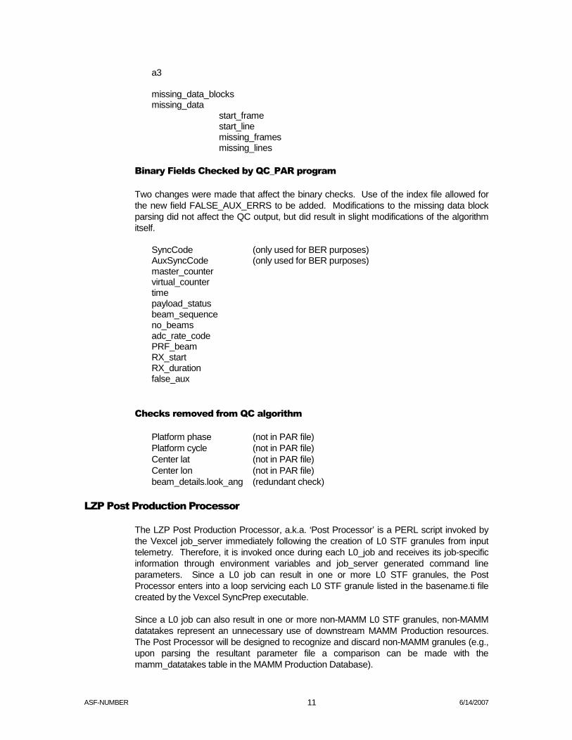
a3 missing_data_blocks missing_data start_frame start_line missing_frames missing_lines
Binary Fields Checked by QC_PAR program
Two changes were made that affect the binary checks. Use of the index file allowed for the new field FALSE_AUX_ERRS to be added. Modifications to the missing data block parsing did not affect the QC output, but did result in slight modifications of the algorithm itself.
SyncCode (only used for BER purposes) AuxSyncCode (only used for BER purposes) master_counter virtual_counter time payload_status beam_sequence no_beams adc_rate_code PRF_beam RX_start RX_duration false_aux
Checks removed from QC algorithm
Platform phase (not in PAR file) Platform cycle (not in PAR file) Center lat (not in PAR file) Center lon (not in PAR file) beam_details.look_ang (redundant check)
LZP Post Production Processor
The LZP Post Production Processor, a.k.a. ‘Post Processor’ is a PERL script invoked by the Vexcel job_server immediately following the creation of L0 STF granules from input telemetry. Therefore, it is invoked once during each L0_job and receives its job-specific information through environment variables and job_server generated command line parameters. Since a L0 job can result in one or more L0 STF granules, the Post Processor enters into a loop servicing each L0 STF granule listed in the basename.ti file created by the Vexcel SyncPrep executable.
Since a L0 job can also result in one or more non-MAMM L0 STF granules, non-MAMM datatakes represent an unnecessary use of downstream MAMM Production resources. The Post Processor will be designed to recognize and discard non-MAMM granules (e.g., upon parsing the resultant parameter file a comparison can be made with the mamm_datatakes table in the MAMM Production Database).

ASF-NUMBER 6/14/2007 12
An overall quality measure of each L0 job can be performed by querying the mamm_l0_jobs table of the MAMM Production Database for the list of MAMM datatakes included in the telemetry segment for that L0 job (l0_job_id).
The following functions are performed by the Post Processor for each L0 STF granule (loop until end of basename.ti file or read file and load array):
1. Call the L0 Job Quality Control function, update MAMM Production database with return status; if error state then e-mail notify the MAMM Production staff with environment variable states, snapshot of system log files, location of any relocated output files, file basenames, etc.
A script that was used for DEM production to analyze data produced for the project was modified for use in the MAMM project. This script takes information from the L0C about the expected data to be produced, then checks the resulting data to see if it what was expected. If there is a match, and the resulting STF data was generated, then QC will succeed. If not, then the script will try to identify the cause of the processing error. The failure could be due to high bit error rate, no TCE, no SVF, etc. The output file generated by QC is analysis.log which is a text file containing information extracted from the resulting data files.
When a L0 production job fails with an error, the files created by the process may be of interest to analyze the problem. The data created during processing will be staged to a temporary directory on the LZP for later analysis. This would include any data created such as capture files in /vxdcs, processed data in /3dsar/TRANS, and log file for the job. Currently, the Operators use the push errors script to relocate data from a failed job to /3dsar/archive/l0_error for analysis. They also clear the system disk after every job with the clear L0 files script. These are accessed through the tool chest menu on JPL1.
2. Call the STF Granule Quality Control Utility (see command line syntax below)
3. Update MAMM Production database with STF Quality Control return status’ verbose definition.
4. Call the QUICKLOOK executable to create a browse file for that L0 STF granule. The processing status table should be updated to include the filename of the resulting quicklook product generated from the STF granule.
Syntax of QuickLook function:
QuickLook –I <L0_ basename> -log <L0_basename>_QuickLook.log –prl 4 –format tif –flip none
Usage: QuickLook –I <L0_basename> [options]
-I <base_name>: input base name for data and par files
Options:
-log <log_file> program log file
-prl <parallel> number of processors to run on
-format <type> output format type (tif)
-flip none

ASF-NUMBER 6/14/2007 13
Filename used by QuickLook Processor:
Basename.000 (.001, .002…) - Input Sky Telemetry Format binary data Basename.000.par - Input parameter file Basename.000.chop - Input framing information file Basename.000.ind - Input index file
The output filename and intermediate files created by QuickLook Processor:
Basename.000.QL.gli - QuickLook image data file Basename.000.QL.gli.par - QuickLook image parameter file Basename.000.QL.tif - QuickLook (tif) file
5. Locate, open and parse the granule’s parameter file (basename.par) and extract the metadata needed to formulate a valid stf_granule_basename:
PPRRRRRQQMMMLATLONGVVV.000.
PP = 2 character satellite platform
RRRRR = 5 digit integer absolute orbit number
QQ = 2 digit integer sequence number
MMM = 3 character beam mode
LAT = 3 character center latitude of datatake
LONG = 4 character center longitude of datatake
VVV = 3 digit integer version number served/managed by the IMS versioning api to guarantee that every L0 granule basename is unique
.000. = 3 digit integer granule number which is always set to zero; expected by SuperCEOS executable for all L0 STF granule basenames
Example: r122345swbn80e123001.000. note: lower case is specified.
6. Create the new basename and apply it to all files in the granule during or prior to file relocation.
7. Using additional metadata from the parameter file, determine which MASTOR directory path to archive the granule files into (need platform, year, and calendar month of datatake):
seinfeld:/dss_stk1/asf_daac/near_line/mou_restricted/l0_sar/R1/2000/sep/ seinfeld:/dss_stk1/asf_daac/near_line/mou_restricted/l0_sar/R1/2000/oct/ seinfeld:/dss_stk1/asf_daac/near_line/mou_restricted/l0_sar/R1/2000/nov/ seinfeld:/dss_stk1/asf_daac/near_line/mou_restricted/l0_sar/R1/2000/dec/ seinfeld:/dss_stk1/asf_daac/near_line/mou_restricted/l0_sar/l0_error/ seinfeld:/dss_stk1/asf_daac/near_line/mou_restricted/l0_sar/l1_error/
ASF-NUMBER 6/14/2007 14
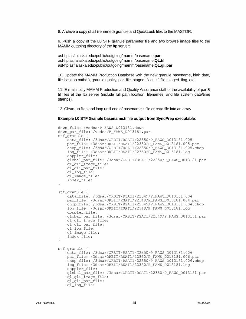
8. Archive a copy of all (renamed) granule and QuickLook files to the MASTOR:
9. Push a copy of the L0 STF granule parameter file and two browse image files to the MAMM outgoing directory of the ftp server:
asf-ftp.asf.alaska.edu:/public/outgoing/mamm/basename.par asf-ftp.asf.alaska.edu:/public/outgoing/mamm/basename.QL.tif asf-ftp.asf.alaska.edu:/public/outgoing/mamm/basename.QL.gli.par
10. Update the MAMM Production Database with the new granule basename, birth date, file location path(s), granule quality, par_file_staged_flag, tif_file_staged_flag, etc.
11. E-mail notify MAMM Production and Quality Assurance staff of the availability of par & tif files at the ftp server (include full path location, filenames, and file system date/time stamps).
12. Clean-up files and loop until end of basename.ti file or read file into an array
Example L0 STF Granule basename.ti file output from SyncPrep executable:
down_file: /vxdcs/P_FAWS_D013181.down down_par_file: /vxdcs/P_FAWS_D013181.par stf_granule { data_file: /3dsar/ORBIT/RSAT1/22350/P_FAWS_D013181.005 par_file: /3dsar/ORBIT/RSAT1/22350/P_FAWS_D013181.005.par chop_file: /3dsar/ORBIT/RSAT1/22350/P_FAWS_D013181.005.chop log_file: /3dsar/ORBIT/RSAT1/22350/P_FAWS_D013181.log doppler_file: global_par_file: /3dsar/ORBIT/RSAT1/22350/P_FAWS_D013181.par ql_gli_image_file: ql_gli_par_file: ql_log_file: ql_image_file: index_file: } stf_granule { data_file: /3dsar/ORBIT/RSAT1/22349/P_FAWS_D013181.004 par_file: /3dsar/ORBIT/RSAT1/22349/P_FAWS_D013181.004.par chop_file: /3dsar/ORBIT/RSAT1/22349/P_FAWS_D013181.004.chop log_file: /3dsar/ORBIT/RSAT1/22349/P_FAWS_D013181.log doppler_file: global_par_file: /3dsar/ORBIT/RSAT1/22349/P_FAWS_D013181.par ql_gli_image_file: ql_gli_par_file: ql_log_file: ql_image_file: index_file: } stf_granule { data_file: /3dsar/ORBIT/RSAT1/22350/P_FAWS_D013181.006 par_file: /3dsar/ORBIT/RSAT1/22350/P_FAWS_D013181.006.par chop_file: /3dsar/ORBIT/RSAT1/22350/P_FAWS_D013181.006.chop log_file: /3dsar/ORBIT/RSAT1/22350/P_FAWS_D013181.log doppler_file: global_par_file: /3dsar/ORBIT/RSAT1/22350/P_FAWS_D013181.par ql_gli_image_file: ql_gli_par_file: ql_log_file:

ASF-NUMBER 6/14/2007 15
ql_image_file: index_file: } stf_granule { data_file: /3dsar/ORBIT/RSAT1/22347/P_FAWS_D013181.001 par_file: /3dsar/ORBIT/RSAT1/22347/P_FAWS_D013181.001.par chop_file: /3dsar/ORBIT/RSAT1/22347/P_FAWS_D013181.001.chop log_file: /3dsar/ORBIT/RSAT1/22347/P_FAWS_D013181.log doppler_file: global_par_file: /3dsar/ORBIT/RSAT1/22347/P_FAWS_D013181.par ql_gli_image_file: ql_gli_par_file: ql_log_file: ql_image_file: index_file: } stf_granule { data_file: /3dsar/ORBIT/RSAT1/22345/P_FAWS_D013181.000 par_file: /3dsar/ORBIT/RSAT1/22345/P_FAWS_D013181.000.par chop_file: /3dsar/ORBIT/RSAT1/22345/P_FAWS_D013181.000.chop log_file: /3dsar/ORBIT/RSAT1/22345/P_FAWS_D013181.log doppler_file: global_par_file: /3dsar/ORBIT/RSAT1/22345/P_FAWS_D013181.par ql_gli_image_file: ql_gli_par_file: ql_log_file: ql_image_file: index_file: } stf_granule { data_file: /3dsar/ORBIT/RSAT1/22347/P_FAWS_D013181.003 par_file: /3dsar/ORBIT/RSAT1/22347/P_FAWS_D013181.003.par chop_file: /3dsar/ORBIT/RSAT1/22347/P_FAWS_D013181.003.chop log_file: /3dsar/ORBIT/RSAT1/22347/P_FAWS_D013181.log doppler_file: global_par_file: /3dsar/ORBIT/RSAT1/22347/P_FAWS_D013181.par ql_gli_image_file: ql_gli_par_file: ql_log_file: ql_image_file: index_file: } stf_granule { data_file: /3dsar/ORBIT/RSAT1/22347/P_FAWS_D013181.002 par_file: /3dsar/ORBIT/RSAT1/22347/P_FAWS_D013181.002.par chop_file: /3dsar/ORBIT/RSAT1/22347/P_FAWS_D013181.002.chop log_file: /3dsar/ORBIT/RSAT1/22347/P_FAWS_D013181.log doppler_file: global_par_file: /3dsar/ORBIT/RSAT1/22347/P_FAWS_D013181.par ql_gli_image_file: ql_gli_par_file: ql_log_file: ql_image_file: index_file: } 13. Update l0_job_quality & stf_granule_status
14. Run the LOPS QC program using the following syntax.

ASF-NUMBER 6/14/2007 16
qc_par <levelZeroBinary> <ConfigFile> <Level>
The values in the brackets are as follows.
<levelZeroBinary> Name of input Level Zero binary data file
<ConfigFile> Name of LOPS QC configuration file
<Level> Level of quality check to perform. Set to 0.
0 - Full binary check
1 - Partial binary check
The return from the test_qc program is as follows:
1. Data is good
2. Data is moderate
3. Data is bad
4. An error occurred in processing
The LOPS QC code creates an ODL file to include output from QC. The QC Engineer will retain this metadata file for later analysis. These files, along with the .qc_log files, will be saved to the mamm_qc directory.
MAMM chop/par file ingest utility
The MAMM Production staff at the Geophysical Institute in Fairbanks, Alaska with the MAMM Project Team at Ohio Stat University work on a 4-hour time-zone difference. For MAMM L1 production, therefore a crontab script polls the ftp server by a script that looks for OSU staged parameter and scene definition files (basename.par, basename.chop). Upon periodic execution this File Ingest Utility will:
1. Poll the ftp site:
ftp.gi.alaska.edu:/home/mamm
2. Retrieve and quality check newly discovered chop & par files. There is a utility running on ftp.gi.alaska.edu to move to ims1.asf.alaska.NASA.gov:/export/FTP/Noltimier/incoming the chop and par files from OSU. Then the chop and par ingest utility retrieves them from ims1 checking for both a par and chop file and does some quality checks then moves then into the silo.
3. If the chop file is for FN1 data, 100 lines are added to the first start_line value. If par file has NR_block or ss_block not equal to 0, then replace with 0.
4. If quality of files is acceptable, rename the original par and chp files in silo to par.asf and par.chop. Then, catalog/archive a copy of the files and update the MAMM Production Database with par & chop file status. Parse a copy of the chop file and load the slc_granules table in the MAMM Production Datatabse by creating one new records for each slc_granule_basename specified in the file ‘output_slc_filename.’

ASF-NUMBER 6/14/2007 17
5. Remove the OSU modified par & chop files from the MAMM incoming ftp server directory, and remove the associated par and tif files staged at the MAMM outgoing ftp server directory:
ftp.gi.alaska.edu:/home/mamm
6. Update the MAMM Production Database for ingested par & chop file locations, advance stf_granule_status to READY. If the quality is good, update OSU_par_status and OSU_chop_status to READY or else to FIX.
7. Notify MAMM Production staff via email of unsuccessful and successful file ingests.
Example basename.chop file received from OSU:
num_scene_lines: 21500 num_overlap_lines: 4096 scene { start_index: 0 start_line: 0 end_index: 21500 end_line: 21500 number_lines: 21500 elevation: 392.0 processor_bandwidth: 1100.0 output_slc_filename: R125280005001 } scene { start_index: 20000 start_line: 20000 end_index: 41500 end_line: 41500 number_lines: 21500 elevation: 184.0 processor_bandwidth: 1050.0 output_slc_filename: R125280006001 }
MAMM L1 Processor
This is a PERL script used for MAMM L1 production during which each L0 STF granule is first processed into variable length scenes by the SuperCEOS executable using the chop file. Then each scene is processed into a L1 single look complex granule by three FOCUS executables (Pre-processor, Range_Doppler, & CEOS_Convert).
The MAMM L1 Processor is invoked by a crontab checking for datatake_status = ‘READY_FOR_L-1_PROCESSING’ when operating in autonomous mode (production queue resides within the MAMM Production Database). An Operator can also check manually once she has received and staged a production queue (text) file containing a list of L0_STF granule basenames, one per line.
The second generation MAMM L1 Processor will report process status to an Operator viewable gui that will include job control commands such as Select, Load, Start, & Abort, will indicate job completion or failure, and will list the successful and unsuccessful L1 SLC granules. A first generation implementation that utilizes a temporary file or equivalent, and updates it with processing states and return code messages per each executable, will ease the introduction of a Tcl/Tk interface at a later date. Job states to include:

ASF-NUMBER 6/14/2007 18
Fetching granule files from silo Fetching state vectors from DADS Invoking SuperCEOS Invoking L1_Pre-processor Invoking Range_Doppler Invoking CEOS_Convert Cataloging/archiving granules files (to IMS/DADS) Steps in L1 processing:
1. Advance slc_granules.slc_granule_status to “IN-PROCESS” so that a different MAMM L1 Processor that is operating in autonomous mode does not simultaneously process it.
2. Using L0 granule basename, query database for L0 file locations, fetch files, copy files to a pre-established working directory whose default path is passed during invocation of the SuperCEOS command, or carried in an environment variable.
3. Fetch all needed input files.
a) Par file fetch (may occur using an IMS/DADS api) b) Chop file fetch (may occur using an IMS/DADS api) c) L0 STF data file fetch from silo
4. Open chop file and extract elevation, processor_bandwidth, output_slc_filename
5. Execute SuperCEOS: Passing L0_granule basename (SuperCEOS expects basename.000
Basename.dat � basename.000 Basename .par � basename.000.par Basename.chop � basename.000.chop
Syntax of SuperCEOS function call:
SuperCEOS –i <L0_basename> –orb /<working_directory_name> –log <L0_basename>_SuperCEOS.log –eph /<ephemeris_directory_name> –pb 0 –pi <L0_basename>.pi
Usage: SuperCEOS [options] –I <base_name> –orb <orbit_dir> –log <log_file>
-I <base_name>: input base name for data and par files -orb <orbit_dir>: output CEOS data set directory -log <log_file>: program log file (stdout by default) Options: -eph <ephem_dir>: directory containing native orbit files -pb <prep_block_nr>: Use this prep block number -pi <product_info_file>: Name for output product_info file Filename used by SuperCEOS Processor: Basename.000 (.001, .002…) - Input Sky Telemetry Format binary data Basename.000.par - Input parameter file Basename.000.chop - Input framing information file

ASF-NUMBER 6/14/2007 19
Basename.000.ind - Input index file The output filename and intermediate files created by Focus Processor: .ldr - L0 CEOS frame leader file .pi - L0 CEOS product information file .raw - L0 CEOS frame (raw) data file .tlr - L0 CEOS frame trailer file .log - Log file of program output
6. Check command return status for error(s), upon error e-mail MAMM production group including QA/QC staff of SuperCEOS failure. Identify basename & file locations. Clean up and update production database with processing status for each granule. Assumption is that failed datatakes will be re-run on a separate QA string (or at later date using production strings).
7. Open resulting basename.pi file, enter into a loop where each pass through will parse in order each CEOS block, grabbing the following fields:
8. Idenitify L0 CEOS file basename & path location
9. Open chop file and extract elevation, processor_bandwidth, output_slc_filename. (this could have been loaded into an array prior to invoking SuperCEOS; )
10. Invoke noise vector script to append to end of the slc.par file.
11. Invoke FOCUS executables in order (pre-processor, range-doppler, ceos-convert) a) Execute FOCUS
PreProcess –alt <terrain_height> –prl 4 –AR MLXX –his <L1_framename>. hist –minANR 12 -log <L1_framename>.log <L0_framename>.raw <L0_framename>.ldr <L1_framename>. par Usage: PreProcess [options] raw aux out
Raw: CEOS raw data input file (parsed from pi file) Aux: CEOS raw auxiliary input file (parsed from pi file) Out: output SAR processing parameter file (parsed from chop file)
Options:
-alt <terrain_height>: Terrain height above ellipsoid (parsed from chop file) -prl <parallel>: Number of processors to run on -AR [MLXX/MLCC/MLBF/SVAR]: Ambiguity resolver algorithm to use MLXX:Best and consistent result -his <hist_filename>: Filename for raw data histogram -log <log_file>: Log filename
b) Execute rd
rd –pl 16384 –kr 2.4 –ka 2.4 –pbw <processor_bandwidth> –slc –prl 4 –log <L1_framename>.log <L0_ framename>.raw <L1_framename>.par <L1_framename>.slc <L1_framename>.slc.par –sigma0 Usage: rd [options] <in_raw> <in_proc_par> <out_image> <out_proc_par>
<In_raw>: CEOS raw data input file (parsed from pi file) <In_proc>: SAR processing parameter file (parsed from chop file)

ASF-NUMBER 6/14/2007 20
<Out_image>: Output SAR processed image (SLC product data) <Out_proc_par>: Output SAR processed parameter file (SLC parameter file)
Options:
-pl <patch_lines>: Number of lines per patch for processing -kr <rc_kaiser_weighting>: Range compression Kaiser parameter -ka <ac_keiser_weighting>: Azimuth compression Kaiser parameter -pbw <proc_bandwidth>: Processor bandwidth (parsed from chop file) -slc: Produce an SLC product -prl <parallel>: Number of processors to run on -log <log_file>: Log filename -sigma0 Choose sigma naught format
c) Execute CEOSconvert
CEOSConvert –i <L1_framename>.slc –p <L1_framename>.slc.par –his <L1_framename>.hist –lea <L1_framename>_slc.ldr –dat <L1_framename>_slc.dat –tra <L1_framename>_slc.tlr –pro SLC –fac CDPF –flip AUTO –rad MPNS –N 3 –log <L1_framename>.log –lut MIXED Usage: CEOSConvert [options] –I in_dat –p in_par –his in_his –pro [SLC/…] –dat out_dat –lea out_lea –tra out_tra –fac [ESA/CDPF] -I in_dat: Input processed SLC data file -p in_par: Input processed SLC parameter file -his in_hist: Input raw data histogram file -pro [SLC/SGC/SGF/SGX/SCN/PRI]: Input product identifier -dat out_dat: Output CEOS dataset filename -lea out_lea Output CEOS leader filename -tra out_tra: Output CEOS trailer filename
Options: -fac [ESA/CDPF]: Output facility name -flip [AUTO/NONE/X/Y/XY] Output image flipping option -rad [LIN/MPNS/LUT] Radiometric stretch for output data -lut MIXED LUT=> loop up table
Stretch: -N value: N value to use if NPNS stretch -log log_file: Log filename
d) Filename used by Focus Processor
Basename.raw - The input CEOS raw dataset file Basename.ldr - The input CEOS raw leader file
e) The output filename and intermediate files created by Focus Processor
.log - Log file of program output
.par - Parameter file output of Parameter Estimator
.hist - Intermediate raw histogram file
.slc - Single look complex image file (SLC)
.slc.par - SLC parameter file

ASF-NUMBER 6/14/2007 21
12. Check return status following each command. If error, then go to error transfer routine detailed below.
13. Archive/catalog resultant product files to IMS/DADS.
14. Update status for product granules within database
15. FOCUS-Error-Routine:
a) Copy SuperCEOS frame files to “Failed FOCUS job staging area” (snapshot of log file, all data & supporting files)
b) Update database with location of files and frame-failure-status:
seinfeld:/archive/asf_daac/near_line/mou_restricted/test&calval/mamm_L1_errors/ L1_SLCgranule_basename
c) E-mail notification to QA/QC staff for investigation, include basename, host/path location, error code returned)
d) Re-enter basename.pi file loop
Example basename.pi file output from SuperCEOS executable:
ceos_block { block_nr: 0 base_name: P_FAWS_D013976 ss_block: 0 prep_block: 0 satellite: RSAT1 beam_sequence: 02 scansar_mode: number_lines: 44754 missing_lines: 0 bit_error_rate: 0.000000 start_date: 20000911104129908 stop_date: 20000911104206376 first_line_first_pixel: 0.000000 0.000000 0.000000 first_line_last_pixel: 0.000000 0.000000 0.000000 last_line_first_pixel: 0.000000 0.000000 0.000000 last_line_last_pixel: 0.000000 0.000000 0.000000 OrbitNr: 25337 output_volume: ./RSAT1/25337/5222.vol output_leader: ./RSAT1/25337/5222.ldr output_data: ./RSAT1/25337/5222.raw output_trailer: ./RSAT1/25337/5222.tlr output_null: ./RSAT1/25337/5222.nul output_pi: ./RSAT1/25337/5222.pi } ceos_block { block_nr: 1 base_name: P_FAWS_D013976 ss_block: 0 prep_block: 0 satellite: RSAT1 beam_sequence: 02 scansar_mode: number_lines: 39046 missing_lines: 0

ASF-NUMBER 6/14/2007 22
bit_error_rate: 0.000000 start_date: 20000911104204123 stop_date: 20000911104235940 first_line_first_pixel: 0.000000 0.000000 0.000000 first_line_last_pixel: 0.000000 0.000000 0.000000 last_line_first_pixel: 0.000000 0.000000 0.000000 last_line_last_pixel: 0.000000 0.000000 0.000000 OrbitNr: 25337 output_volume: ./RSAT1/25337/5260.vol output_leader: ./RSAT1/25337/5260.ldr output_data: ./RSAT1/25337/5260.raw output_trailer: ./RSAT1/25337/5260.tlr output_null: ./RSAT1/25337/5260.nul output_pi: ./RSAT1/25337/5260.pi } ceos_block { block_nr: 2 base_name: P_FAWS_D013976 ss_block: 0 prep_block: 0 satellite: RSAT1 beam_sequence: 02 scansar_mode: number_lines: 35119 missing_lines: 0 bit_error_rate: 0.000000 start_date: 20000911104233687 stop_date: 20000911104302304 first_line_first_pixel: 0.000000 0.000000 0.000000 first_line_last_pixel: 0.000000 0.000000 0.000000 last_line_first_pixel: 0.000000 0.000000 0.000000 last_line_last_pixel: 0.000000 0.000000 0.000000 OrbitNr: 25337 output_volume: ./RSAT1/25337/5293.vol output_leader: ./RSAT1/25337/5293.ldr output_data: ./RSAT1/25337/5293.raw output_trailer: ./RSAT1/25337/5293.tlr output_null: ./RSAT1/25337/5293.nul output_pi: ./RSAT1/25337/5293.pi } ceos_block { block_nr: 3 base_name: P_FAWS_D013976 ss_block: 0 prep_block: 0 satellite: RSAT1 beam_sequence: 02 scansar_mode: number_lines: 6681 missing_lines: 0 bit_error_rate: 0.000000 start_date: 20000911104300051 stop_date: 20000911104305495 first_line_first_pixel: 0.000000 0.000000 0.000000 first_line_last_pixel: 0.000000 0.000000 0.000000 last_line_first_pixel: 0.000000 0.000000 0.000000 last_line_last_pixel: 0.000000 0.000000 0.000000 OrbitNr: 25337 output_volume: ./RSAT1/25337/5311.vol output_leader: ./RSAT1/25337/5311.ldr output_data: ./RSAT1/25337/5311.raw output_trailer: ./RSAT1/25337/5311.tlr

ASF-NUMBER 6/14/2007 23
output_null: ./RSAT1/25337/5311.nul output_pi: ./RSAT1/25337/5311.pi }
e) End Loop (on detected end-of-file (EOF), perform file clean-up and exit.
L0 Electronic Queue
An electronic queue has been developed for L0 production to replace the previous method of using a manual queue. The manual queue was a printed spreadsheet passed from the ASF Production Planners to the ASF Operators, which required the ASF Operators to type in long start and stop addresses. The risk of errors with the repetitious, manual process has been greatly reduced by the electronic queue.
The new electronic queue is a web-based application that allows the ASF Production Planner to load either a tab-delimited text file of granules and associated data or datatakes one at a time. This queue allows multiple views based on the state of the job, ex. “Ready”, “Planned”, “Failed”, and “Canceled”. It keeps an electronically searchable history of all jobs ever entered.
From an operations perspective the queue is simple to use. Operators pick a recorder and a processor, type in their initials and scan a “dog tag” label. After the datatake is run, they move it to either “Failed” or “Complete”. They can also add any notes or copy and paste error messages as necessary.

ASF-NUMBER 6/14/2007 24
External Interface Design
Interface with OSU
Export metadata files
ASF exports the metadata files required by OSU Operator for pre-processing via ftp. The files are staged to the ftp and made available for the OSU Operator to pull the files as needed. Details are described in the description of the LZP Post Processor script above.
Import chop files
The OSU Operator generates the chop files required by ASF for processing and exports them via ftp. The files are staged to the ftp site and made available for the ASF Operator to pull the files as needed. Details are described in the MAMM chop/par ingest utility section above.
Export data products
The final data products will be written to media and shipped to OSU using a mail courier. The type of media is designated in the EDG order and has been specified as DLT for this project.

ASF-NUMBER 6/14/2007 25
Requirements Allocation and Tracing
Production and Interface Requirements
4.1.1 ASF shall provide OSU with a list of MAMM datatakes.
4.1.1.1 ASF shall provide OSU a Job Identifier for each datatake.
4.1.1.2 ASF shall provide OSU the Satellite Revolution Number for each datatake.
4.1.1.3 ASF shall provide OSU the Beam Mode for each datatake.
4.1.1.4 ASF shall provide OSU the Sequence Number of each datatake.
4.1.1.5 ASF shall provide OSU the ASF Frame Numbers for each datatake.
4.1.2 ASF shall accept MAMM datatake orders starting March 1, 2001.
4.1.3 ASF shall provide preliminary ancillary files to OSU for each MAMM datatake. [1]
4.1.3.1 ASF shall provide Vexcel Level-zero STF granule parameter (“par”) files for each datatake ordered by OSU by FTP.
4.1.3.2 ASF shall provide Vexcel Level-zero STF tagged image file format (“tif”) files for each datatake ordered by OSU by FTP.
4.1.3.3 ASF shall provide Vexcel a “par” file for each “tif” file
4.1.4 ASF shall receive ancillary files for each datatake ordered by OSU.
4.1.4.1 ASF shall receive updated ancillary files from OSU via FTP.
4.1.4.1.1 ASF shall receive modified Vexcel Level-zero STF granule parameter (“par”) files for each datatake ordered by OSU.
4.1.4.1.2 ASF shall receive MAMM-specific Level-zero STF “chop” files for each datatake ordered by OSU.
4.1.5 ASF shall ship completed SLC products to OSU on DLT tapes.
4.1.5.1 ASF shall label the SLC data tapes with the order number.
4.1.5.2 ASF shall label the SLC data tapes with the SLC basenames as included in the “chop” file.

ASF-NUMBER 6/14/2007 26
MAMM Specific Processing Parameters
Radar delay
Gain and offset for the processor to adjust the DN distribution
What else?

ASF-NUMBER 6/14/2007 27
Appendix A: L0 STF Production Design
WS tape
L0C
Silo
OSU
FTP Server
LZP
LZP Post Processor
Metadata QC Filter Files Browse image created Binary QC Rename files Push files
.Tar file with .par & .tiff Files
Email Errors Or Email tar Success
L0 Files
MAMM Production Database
Planner input
I
Process Queue
Email OSU tar file ready
Mamm_logs

ASF-NUMBER 6/14/2007 28
Appendix B: L1 Production Design
Silo GI ftp Server
OSU
Modified OSU chop &.par Mamm_File_Ingest
Chop_fix & par_fix
MAMM_L1_processor
CEOS Processor
How to deal with fails?
Extract info from .chop & Associate with correct frame
Focus Processor
Get L0 Product & .chop File
email QA & Planners
email Planners
GUI for Ops
MAMM Production Database
Failed SLC + input files
GUI Mamm_auto_l1
IMS1 ftp server
Mamm_giftp2ims
Good SLCs on disk
Export_to_ims - catalog SLC granules in IMS
Add noise vector & Rename
IMS
Update granule status
Delete from disk
email Planners
OSU chop & par

ASF-NUMBER 6/14/2007 29
Appendix C: DLT Production Design
Silo
DADs Tape Write Utility
EDG w/ Dynamic Valids or
ims_order
DLT & tar report
OSU
MAMM Production Database
IMS
GUI