aseptic peristaltic pump design jason binz matt giordano craig lebro alex reeser scientific products...
TRANSCRIPT

1
Aseptic Peristaltic Pump Design
Jason Binz
Matt Giordano
Craig Lebro
Alex Reeser
Scientific Products & Systems, Inc

22
About SP&S
Scientific Products and Systems, Inc.
Specialize in high precision pumping systems
– Used for Pharmaceutical, Specialty chemicals
and other precision pumping applications
OnePump®, OneBloc® systems
– Positive displacement pumps
– Peristaltic Pumps
http://www.spspump.com/

33
Project Scope
SP&S feels a reusable, high precision pump will launch company to top of market for pumping specialty chemicals
Design a new pump for integration into
existing OneBloc® and OnePump ® system
Retain the high precision found in existing pumps
http://www.spspump.com/

4
Considerations for Design
Designer drugs lead to problems with cleaning– Autoclave– Vaporized Hydrogen Peroxide
Previous assembly usually discarded if the tube breaks
Limit number of tools for head removal

55
What is a Peristaltic Pump?
Positive Displacement Pump– Used for high precision/low volume
pumping– Benefits
Only tubing comes in contact with fluid
Very accurate volume control– Only limited by motor and
torque transmission to head– Downsides
Tube breakage if not maintained properly
Can lose precision with pumping due to wear in tube

66
SP&S Wants for New Design
Precision pumping– Utilize existing micro stepping drive system
Capable of at least 51,200 steps for ultra-high precision
Needed for pumping small volumes
Head Design– Single tubing
Allows for tube to be advanced when worn Capable of placing tube above and below rollers
– Allows for alternating pulses Holders to maintain tension in tubing
– Rollers PEEK material, Odd number
– Stainless steel pressure shoes

77
Design Metrics
Metrics determined from SP&S wants and restrictions
Used to compare different design concepts

88
Subsystem Design
Adjustable height
Cam Cleat Spring
Clamp
Fixed
Lever Controlled
Spring Clamp
Bar and Latch
Gear Clamp
Cam-Follower
Tube Tensioner
Shoe Design
Square with rounded
ends
Star Pattern
Square
Threaded Clasp
Half Circle
Aseptic
Peristaltic Pump Head
Tube Tensioner
Shoe Design
Roller Head Shaft
Spring Clasps

99
Shaft Geometry
Used precision comparison to narrow down to two
shaft geometries
– Both give excellent torque transmission Spline
Squared-off round shaft
Square-off round chosen
– Less recessed surfaces
– Makes it easier to clean with vaporized hydrogen
peroxide
– More difficult to manufacture, but better satisfied
design metrics

1010
Roller Head
Circular head– Easily manufactured– Allows for varying number of
rollers– Held on by Knurled nut to be
tightened by hand Rollers
– PEEK rollers – Range from 3-7 rollers
Less rollers for higher volume displacement
Still maintain accuracy and precision of pump
Combination of roller and head materials chosen to satisfy autoclave metric
All components easily taken apart to ensure thorough cleaning

1111
Shoe Design
Adjustable Shoe Height– Allows to use range of tubes and maintain precision
Comparison of different designs to hold shoe to cover plate– Bail Latch
Difficult to clean mechanism Uneven wear in latches can lead to uneven pressure
across shoe and decreased precision– Cam Latch
Easily cleaned in autoclave Little wear
– Maintain constant shoe force after repeated use Easily latches to center base without tools Center piece holds top and bottom shoe as well as tube
– Stainless steel so that it can be autoclaved Top and bottom shoe could discarded in event of tube
breakage Cam Latch was chosen since it satisfied more design
metrics
12
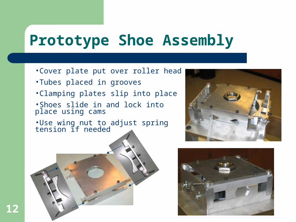
Prototype Shoe Assembly
•Cover plate put over roller head
•Tubes placed in grooves
•Clamping plates slip into place
•Shoes slide in and lock into place using cams
•Use wing nut to adjust spring tension if needed

1313
Tube Tensioner
During pumping– Tube stretches
After pumping – Tube experiences elastic recoil
For low volume dispensing, this can cause large discrepancies in precision
– Tensioner used to prevent recoil to maintain precision
Final decision was to use compression fittings with spring tensioners
– Cheap enough to discard if tube breaks
– Easy to disassemble to advance tube
– Ensures desired precision
Compression fitting holds tube on other side
Spring will have protective jacket on inside to prevent damage to tube

1414
Final Design Concept Proposal
Due to Cams, head mounted horizontally

15
Attach Roller HeadPlace Cover OnPlace Tube In SlotSlide Shoes in PlaceClamp Shoes to Cover PlateFinal Prototype
Final Design Concept Proposal

16
Cost Analysis
Senior Design Aspect Prototype Costs
– $2,000– Covers:
all prototype materials test stand Motor
Final Production Approximate Product Costs
– With Motor $2,800 - $3,300
– Without Motor $2,000 – $2,500
Replacement Parts– $150 - $200– Covers cost of replacement
package for discarded parts Tubing and Tensioners Springs and Shoe Parts16
1717
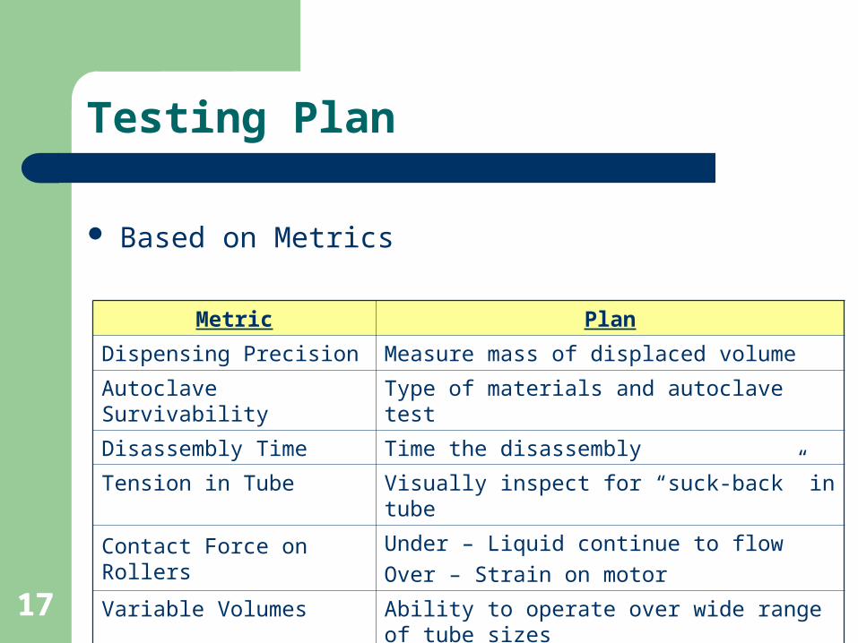
Testing Plan
Based on Metrics
Metric Plan
Dispensing Precision Measure mass of displaced volume
Autoclave Survivability Type of materials and autoclave test
Disassembly Time Time the disassembly
Tension in Tube Visually inspect for “suck-back” in tube
Contact Force on RollersUnder – Liquid continue to flow
Over – Strain on motor
Variable Volumes Ability to operate over wide range of tube sizes

18
Concept Validation
Tube Sizes
Precision Testing3 mL Dispensing Test
Average [mL] Standard Deviation [mL] Relative Standard Dev. [%]
Small (Slow Speed) 3.0150 0.0683 2.26
Small (Fast Speed) 2.9932 0.0633 2.12
Medium 2.9832 0.1548 5.19
Large 3.0063 0.0114 0.38
5 mL Dispensing Test
Small 5.1050 0.1159 2.27
Medium 4.9901 0.0381 0.76
Large 4.9893 0.0836 1.68
10 mL Dispensing Test
Small 9.9919 0.1216 1.22
Medium 10.0064 0.12570 1.27
Large 10.0392 0.0635 0.63
Small Medium Large
3.2 mm ID 6.4 mm ID 9.6 mm ID

19
Concept Validation
3 mL Test of Different Tube Diameters for Peristaltic Pump
2.6
2.7
2.8
2.9
3.0
3.1
3.2
3.3
3.4
1 6 11 16 21 26 31
Trial Number [a.u.]
Vo
lum
e D
isp
en
se
d [
mL
]
3.2 mm Tube Run 1
3.2 mm Tube Run 2
6.4 mm Tube
9.6 mm Tube

20
Concept Validation
5 mL Test of Different Tube Diameters for Peristaltic Pump
4.8
4.9
5.0
5.1
5.2
5.3
5.4
1 6 11 16 21 26 31
Trial Number [a.u.]
Vo
lum
e D
isp
ense
d
3.2 mm Tube
6.4 mm Tube
9.6 mm Tube

21
Concept Validation
10 mL Test of Different Tube Diameters for Peristaltic Pump
9.70
9.75
9.80
9.85
9.90
9.95
10.00
10.05
10.10
10.15
10.20
1 6 11 16 21 26 31 36
Trial Number [a.u.]
Vo
lum
e D
isp
en
se
d [
mL
]
3.2 mm Tube
6.4 mm Tube
9.6 mm Tube

22
Visual Observations
Precision not achieved due to prototype machining– Parts were modified to be assembled
Allowed for shoes to travel and shaft raised slightly during testing
– Manufacturing processes can be changed to increased precision and reduce shoe movement
Tube Tension– Saw visual suck-back
Not enough tension on tube Need to modify tube tensioner to keep steady pressure
Shoe Pressure– Adjustment nut allowed to shoes to be raised or lowered to
achieve optimal pressure

23
Disassembly Time
Average disassembly time for group members– 28.62 s
Average disassembly time for test subjects– 44.59 s
Overall Average– 36.60 s
Test group was large enough to determine the target value of <1 min was achieved
2424
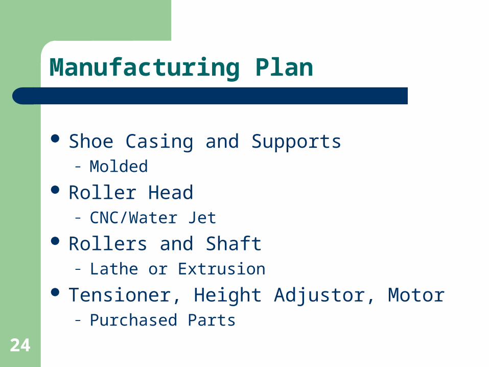
Manufacturing Plan
Shoe Casing and Supports – Molded
Roller Head – CNC/Water Jet
Rollers and Shaft– Lathe or Extrusion
Tensioner, Height Adjustor, Motor– Purchased Parts

25
Integration in SP&S Product Line
OneBloc® System– Pump designed to be easily integrated into this
system– Replaces current design with only modification in
attachment point OnePump®
– Currently has vertical arrangement– Need to add gear box to achieve the horizontal
design Both can be achieved simply with little
modification, additions, or costs

2626
Acknowledgements
SP&S– Mr. David Bach– Mr. Milton Cochran– Mr. Ronald Genova– SP&S Staff– Tom Cassidy
University of Delaware– Dr. Robert Hartman– Mr. Steve Beard– Mr. Roger Stahl– Senior Design Advisors

27
Detailed Project Costs
27
Project CostsObjective TimeDesign and DevelopmentBrainstorming 200CAD 150Drawing 50
FabricationAssembly 50Machine time 75
Testing and AnalysisAnalysis 50Proof of Concept 25Redesign/Error 15Total 615
Team Cost ($200 per hr) $123,000

28
Detailed SP&S Prototype Costs
28
SP&S CostsMaterials Qty Cost/ Qty CostPEEK Rollers 7 $9.00 $63.00Stainles Steel Rod 12" 1 $30.00 $30.00SS Sheet 12"x12"x1/8" 2 $100.00 $200.00SS Sheet 12"x12"x1/4" 5 $150.00 $750.00Hardware 10 $10.00 $100.00Compression Fittings 4 $10.00 $40.00MForce 34 Motor 1 $800.00 $800.00Tubing 50 $2.00 $100.00Gear Box 1 $75.00 $75.00
Subtotal $2,158.00
Machining Shops Hours Cost/ Hour CostStudent 100 $10.00 $1,000.00Outsource 50 $50.00 $2,500.00Colburn 25 $30.00 $750.00
Subtotal $4,250.00Overhead 1.5 $6,375.00
Total $8,533.00
29
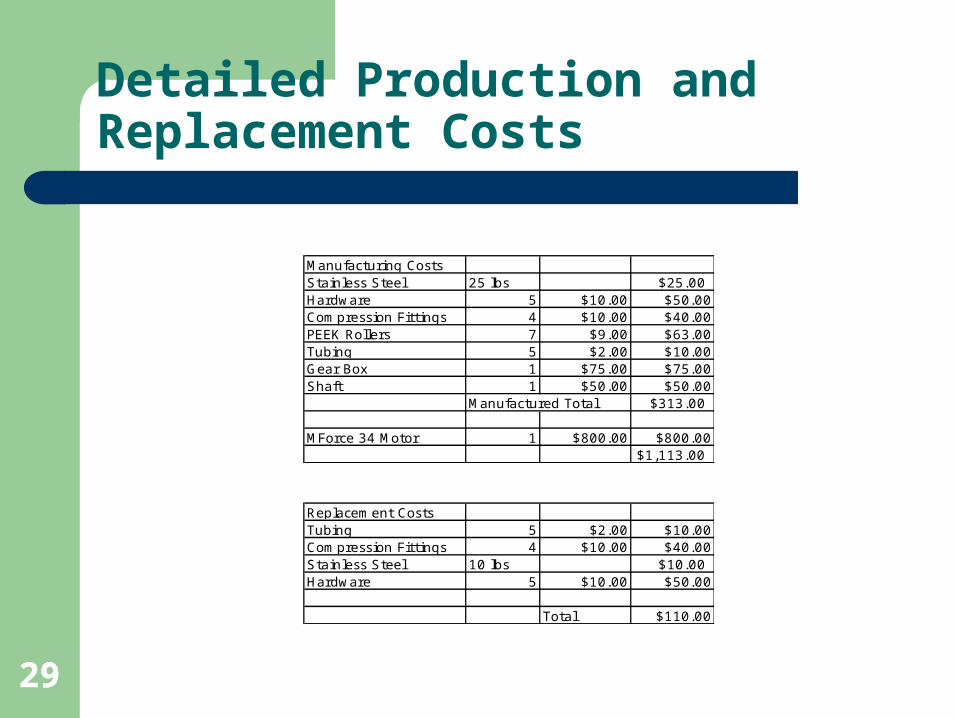
Detailed Production and Replacement Costs
29
Replacement CostsTubing 5 $2.00 $10.00Compression Fittings 4 $10.00 $40.00Stainless Steel 10 lbs $10.00Hardware 5 $10.00 $50.00
Total $110.00
Manufacturing CostsStainless Steel 25 lbs $25.00Hardware 5 $10.00 $50.00Compression Fittings 4 $10.00 $40.00PEEK Rollers 7 $9.00 $63.00Tubing 5 $2.00 $10.00Gear Box 1 $75.00 $75.00Shaft 1 $50.00 $50.00
Manufactured Total $313.00
MForce 34 Motor 1 $800.00 $800.00$1,113.00

3030
Alternative Tube Tensioner
Cam Cleats– Allows for one tube
to move in one direction
Spring Clamp – Hold tube in place
Design– Either use cam cleat
on both sides or on one side
– Thoughts?http://www.petticrows.com

3131
Alternate Shoe Designs
Cam follower
Lever Controlled
Spring Clamp
3232
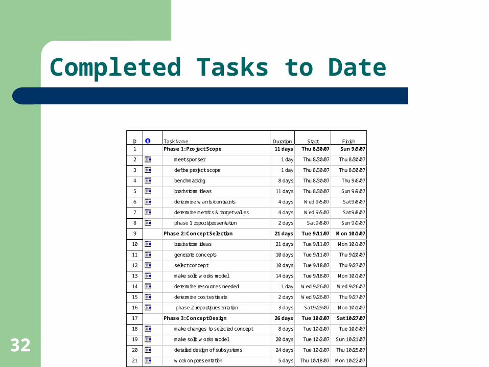
Completed Tasks to Date
ID Task Name Duration Start Finish
1 Phase 1: Pro ject Scope 11 days Thu 8/30/07 Sun 9/9/07
2 meet sponser 1 day Thu 8/30/07 Thu 8/30/07
3 define project scope 1 day Thu 8/30/07 Thu 8/30/07
4 benchmarking 8 days Thu 8/30/07 Thu 9/6/07
5 brainstorm ideas 11 days Thu 8/30/07 Sun 9/9/07
6 determine w ants/contraints 4 days Wed 9/5/07 Sat 9/8/07
7 determine metrics & target values 4 days Wed 9/5/07 Sat 9/8/07
8 phase 1 repor t/presentation 2 days Sat 9/8/07 Sun 9/9/07
9 Phase 2: Concept Selection 21 days Tue 9/11/07 Mon 10/1/07
10 brainstrom ideas 21 days Tue 9/11/07 Mon 10/1/07
11 generate concepts 10 days Tue 9/11/07 Thu 9/20/07
12 select concept 10 days Tue 9/18/07 Thu 9/27/07
13 make solid w orks model 14 days Tue 9/18/07 Mon 10/1/07
14 determine resources needed 1 day Wed 9/26/07 Wed 9/26/07
15 determine cos t estimate 2 days Wed 9/26/07 Thu 9/27/07
16 phase 2 report/presentation 3 days Sat 9/29/07 Mon 10/1/07
17 Phase 3: Concept Design 26 days Tue 10/2/07 Sat 10/27/07
18 make changes to selected concept 8 days Tue 10/2/07 Tue 10/9/07
19 make solid w orks model 20 days Tue 10/2/07 Sun 10/21/07
20 detailed design of subsystems 24 days Tue 10/2/07 Thu 10/25/07
21 w ork on pres entation 5 days Thu 10/18/07 Mon 10/22/07

3333
Future Tasks
Tasks that still need to be completed
ID Task Name Duration Start Finish
22 determine how to assemble subystems 6 days Sat 10/20/07 Thu 10/25/07
23 determine manufacturing process 6 days Sat 10/20/07 Thu 10/25/07
24 develop testing plans 2 days Wed 10/24/07 Thu 10/25/07
25 phase 3 repor t 2 days Fri 10/26/07 Sat 10/27/07
26 Phase 4: Per formance Validation 40 days Mon 10/29/07 Fri 12/7/07
27 build prototype 22 days Mon 10/29/07 Mon 11/19/07
28 test prototype 13 days Tue 11/20/07 Sun 12/2/07
29 redesign (if needed) 8 days Sun 11/25/07 Sun 12/2/07
30 final report/presentation 5 days Mon 12/3/07 Fri 12/7/07

3434
Phase 1 Completed Task Schedule
ID Task Name
1 Phase 1: Project Scope
2 meet sponser
3 define project scope
4 benchmarking
5 brainstorm ideas
6 determine w ants/contraints
7 determine metr ics & target values
8 phase 1 report/presentation
9 Phase 2: Concept Selection
17 Phase 3: Concept Design
26 Phase 4: Performance Validation
W T F S S M T W T F S S MSep 2, '07 Sep 9,

3535
Phase 2 Completed Task Schedule
ID Task Name
1 Phase 1: Pr oject Scope
9 Phase 2: Concept Selection
10 brainstrom ideas
11 generate concepts
12 select concept
13 make solid w orks model
14 determine resources needed
15 determine cost estimate
16 phase 2 report/presentation
17 Phase 3: Concept Design
26 Phase 4: Pe rformance Validation
M T W T F S S M T W T F S S M T W T F S S M T 9, '07 Sep 16, '07 Sep 23, '07 Sep 30, '0

3636
Phase 3 Completed Task Schedule
ID Task Name
1 Phase 1: Project Scope
9 Phase 2: Concept Selection
17 Phase 3: Concept Design
18 make changes to selected concept
19 make solid w orks model
20 detailed design of subsystems
21 w ork on presentation
22 determine how to assemble subystems
23 determine manufacturing process
24 develop testing plans
25 phase 3 report
26 Phase 4: Performance Validation
T W T F S S M T W T F S S M T W T F S S M T W T F S S M, '07 Oct 7, '07 Oct 14, '07 Oct 21, '07 Oct 28

3737
Phase 4 Future Work
ID Task Name
1 Phase 1: Project Scope
9 Phase 2: Concept Selection
17 Phase 3: Concept Design
26 Phase 4: Per formance Validation
27 build prototype
28 test prototype
29 redesign (if needed)
30 final report/presentation
M T W T F S S M T W T F S S M T W T F S S M T W T F S S M T W T F S S M T W T F S 28, '07 Nov 4, '07 Nov 11, '07 Nov 18, '07 Nov 25, '07 Dec 2, '07

3838

3939

4040