as1684 split level c2 house bracing
TRANSCRIPT

8/19/2019 As1684 Split Level c2 House Bracing
http://slidepdf.com/reader/full/as1684-split-level-c2-house-bracing 1/43
Understanding AS1684Residential Timber Framed Construction
Bracing example

8/19/2019 As1684 Split Level c2 House Bracing
http://slidepdf.com/reader/full/as1684-split-level-c2-house-bracing 2/43
2
Bracing Example
• C2
• Split level
• Dutch gable roofs
• Ceiling height 2560• Eaves 600mm
• Roof pitch 25o
North elevation
East elevation
1604 + depth
roof frame
900
2077 +
depth ofroof frame
1120
Wind
direction 2Level 1 and Level 2
Wind
direction 1
Level 1
Level 2
Wind Direction 1
WindDirection 2

8/19/2019 As1684 Split Level c2 House Bracing
http://slidepdf.com/reader/full/as1684-split-level-c2-house-bracing 3/43
3
Level 3Wind
Direction 2 Level 3
Wind Direction 1
Bracing Design Process (Clause 8.3.1)
1. Determine the wind classification Clauses 1.4.2 & 1.5 & AS4055/AS/NZS1170.2
2. Determine the wind pressure Clause 8.3.2 & Tables 8.1 to 8.5
3. Determine the area of elevation Clause 8.3.3 and Figure 8.2(A) or (B)
4. Calculate the racking force Clause 8.3.4 and Tables 8.1 to 8.5
5. Design the bracing systems
- Sub-floors Clause 8.3.5, Fig 8.4, Tables 8.7 - 8.16, C1 only
- Walls Clause 8.3.6, Tables 8.18 and 8.19
6. Check even distribution and spacing Clause 8.3.6.6 and 8.3.6.7, Tables 8.20 – 8.21
7. Connection of bracing to Clause 8.3.6.9 and 8.3.6.10, Table 8.23
roof/ceilings at walls and floors AS1684.3 pg108
and Figs 8.5 – 8.6

8/19/2019 As1684 Split Level c2 House Bracing
http://slidepdf.com/reader/full/as1684-split-level-c2-house-bracing 4/43
4
1. Determine the Wind Classification
C2(provided by structural engineer,
building professional or local building authority)
Refer Clause 1.4.2 [pg 9] and AS 4055 or
AS/NZS 1170.2
2. Determine the wind pressure
(for both wind directions)
See Clause 8.3.2 [pg 108] also
Tables 8.1 to 8.5 [pgs 112 –120]
Need:
• the roof pitch,
• the width of the building, and
• whether there are any flat walls, skillion ends,
gable (or Dutch gables) or hip ends.
Complex designs may require separate
pressures within the one wind direction as is
the case in this example.

8/19/2019 As1684 Split Level c2 House Bracing
http://slidepdf.com/reader/full/as1684-split-level-c2-house-bracing 5/43
5
Dutch Gables
In this example, the house has Dutch gables which are
neither a full gable or a hip end as described by the
pressure tables in AS 1684.3.
It is recommended that where the height of the Dutch
gable (a) is equal to or less than half the full height to
the ridge (h), that the Dutch gable end be treated as a
hip end. If ‘a’ is greater than 1/2h, then treat the Dutch
gable end as a full gable end.
a
h
Dutch gable
Hip rooflong side
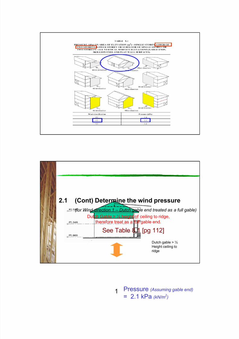
2.1 Determine the wind pressure
(for Wind direction 1)
See Table 8.1 [pg 112] and Table 8.2 [pg 113]
Split the house into it’s two components
• Two storey section with Dutch gable
• Single storey hip roof (long length of building)
1
Dutch gable
end
8/19/2019 As1684 Split Level c2 House Bracing
http://slidepdf.com/reader/full/as1684-split-level-c2-house-bracing 6/43
6
Single storey Hip
roof long side
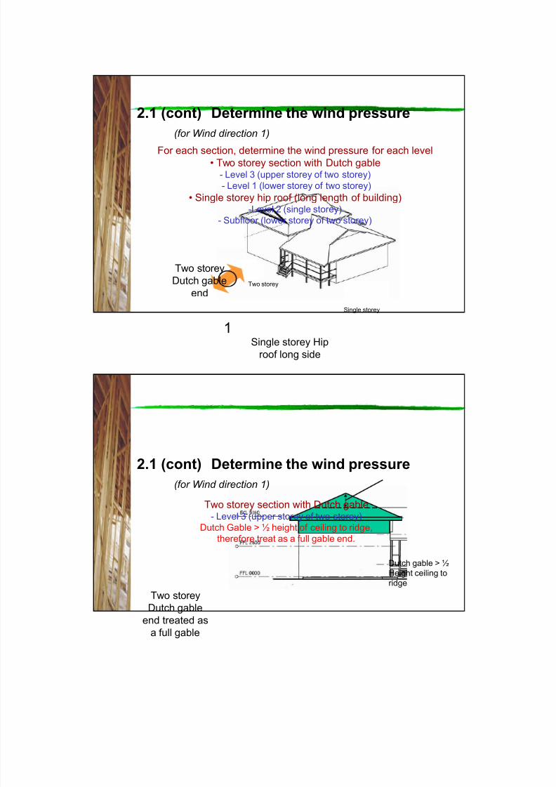
2.1 (cont) Determine the wind pressure
(for Wind direction 1)For each section, determine the wind pressure for each level
• Two storey section with Dutch gable- Level 3 (upper storey of two storey)
- Level 1 (lower storey of two storey)
• Single storey hip roof (long length of building)-Level 2 (single storey)
- Subfloor (lower storey of two storey)
1
Two storey
Dutch gable
end
Single storey
Two storey
2.1 (cont) Determine the wind pressure
(for Wind direction 1)
Two storey section with Dutch gable- Level 3 (upper storey of two storey)
Dutch Gable > ½ height of ceiling to ridge,
therefore treat as a full gable end.
Two storey
Dutch gable
end treated as
a full gable
Dutch gable > ½
Height ceiling to
ridge
8/19/2019 As1684 Split Level c2 House Bracing
http://slidepdf.com/reader/full/as1684-split-level-c2-house-bracing 7/43
7
Pressure (Assuming gable end)
= 2.1 kPa (kN/m2
)
See Table 8.1 [pg 112]
2.1 (Cont) Determine the wind pressure
(for Wind direction 1 – Dutch gable end treated as a full gable)
Dutch Gable > ½ height of ceiling to ridge,
therefore treat as a full gable end.
1
Dutch gable > ½
Height ceiling to
ridge

8/19/2019 As1684 Split Level c2 House Bracing
http://slidepdf.com/reader/full/as1684-split-level-c2-house-bracing 8/43
8
2.1 (cont) Determine the wind pressure
(for Wind direction 1)Two storey section with Dutch gable
- Level 1 (lower storey of two storey)
Dutch Gable > ½ height of ceiling to ridge,
therefore treat as a full gable end.
Two storey
Dutch gableend
Dutch gable > ½
Height ceiling to
ridge

8/19/2019 As1684 Split Level c2 House Bracing
http://slidepdf.com/reader/full/as1684-split-level-c2-house-bracing 9/43
9
2.1 (cont) Determine the wind pressure
(for Wind direction 1 gable end)
Pressure (Assuming gable end)
= 2.1 kPa (kN/m2 )
See Table 8.1 [pg 112]
1
2560
2600 2400
Dutch gable > ½
Height ceiling to
ridge
2.1 (cont) Determine the wind pressure
(for Wind direction 1 – hip end long side of building)
Single storey section- Level 2 (single storey)
Single storey
hip roof long
side

8/19/2019 As1684 Split Level c2 House Bracing
http://slidepdf.com/reader/full/as1684-split-level-c2-house-bracing 10/43
10
Wind
direction 2
Level 3
Level 1 and Level 2
Wind
direction 1
Actual
8.910

8/19/2019 As1684 Split Level c2 House Bracing
http://slidepdf.com/reader/full/as1684-split-level-c2-house-bracing 11/43
11
2.1 (cont) Determine the wind pressure
(for Wind direction 1 –
hip end long side of building)
Single storey -
hip roof - longside
Building Width is 8.91m, but
say 9.0m, as interpolation
would not gain a lot in this
case
Pressure
= 1.7 kPa (kN/m2 )
1
See Table 8.2 [pg 113]
Actual
8.910

8/19/2019 As1684 Split Level c2 House Bracing
http://slidepdf.com/reader/full/as1684-split-level-c2-house-bracing 12/43
12
2.1 (cont) Determine the wind pressure
(for Wind direction 1 –
hip end long side of building)
Lower storey of
two storey or
sub-floor of
single storey
Building Width is 8.91m, but
say 9.0m, as interpolation
would not gain a lot in this
case
Pressure
= 1.9 kPa (kN/m2 )
1
See Table 8.3 [pg 115]
Hip roof
long side
2.2 Determine the wind pressure
(for Wind direction 2 )
As the wind in direction 2 can come from either side onto the east or west
elevation, a decision is required on how to account for the worst case.
The house is also split level, so other decisions are also required on how
the wind will be distributed into bracing walls in each level. This matter will
be discussed later.
Dutch gable
end
2East elevation
West elevation
North elevation

8/19/2019 As1684 Split Level c2 House Bracing
http://slidepdf.com/reader/full/as1684-split-level-c2-house-bracing 13/43
13
2.2 (cont) Determine the wind pressure
(for Wind direction 2 –
Hip end –
Long length of building orfrom Dutch gable end)
2
East elevation
As can be seen from the
elevation, the single storey
(Level 2) section of the house
falls almost entirely within the
area envelope of the two storey
section. The rear patio is
assumed to remain open. The
front porch is assumed to be
closed one end by lattice.
Also, as the height of the Dutch gable on the east
elevation is equal or less than half the overall
height to the ridge of the roof, this can be treated
as a hip end similar to the hip roof from the west
elevation. This section of gable will therefore not
result in greater forces than that of the hip roof so
it can be ignored in this regard.
It is therefore recommended to consider the wind for Direction 2 on the two storey
section, and make allowance for any additional small areas of elevation (as shown
in orange) outside of the two storey section and account for these forces
appropriately where these areas are also considered as a hip.
Discussion
Actual
6.8806.9 1.6
Interpolation
permitted
but not
necessary

8/19/2019 As1684 Split Level c2 House Bracing
http://slidepdf.com/reader/full/as1684-split-level-c2-house-bracing 14/43
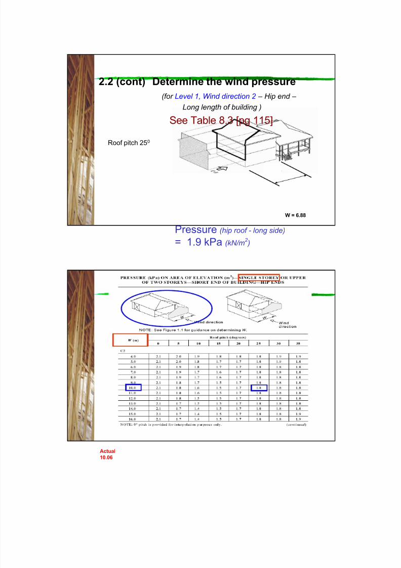
14
2.2 (cont) Determine the wind pressure
(for Level 3, Wind direction 2 –
Hip end –
Long length of building )
Roof pitch 250
Pressure (hip roof - long side)
= 1.6 kPa (kN/m2 )
See Table 8.2 [pg 113]
W = 6.88
Actual
6.880 6.9 1.9
Interpolation
permittedbut not
necessary
8/19/2019 As1684 Split Level c2 House Bracing
http://slidepdf.com/reader/full/as1684-split-level-c2-house-bracing 15/43
15
2.2 (cont) Determine the wind pressure
(for Level 1, Wind direction 2 –
Hip end –
Long length of building )
Roof pitch 250
Pressure (hip roof - long side)
= 1.9 kPa (kN/m2 )
See Table 8.3 [pg 115]
W = 6.88
Actual
10.06

8/19/2019 As1684 Split Level c2 House Bracing
http://slidepdf.com/reader/full/as1684-split-level-c2-house-bracing 16/43
16
Note: The additional
areas highlighted in
orange, outside the
envelope of the two-
storey section are
considered as pressure
on a hip end (rather than
gable), as the height of
the Dutch gable on thiselevation is less than ½
the height from ceiling to
to the ridge.
2.2 (cont) Determine the wind pressure
(for Level 1, Wind direction 2 –
Short end of building - Hip end )
Roof pitch 250
Pressure (Hip roof end of building )
= 1.8 kPa (kN/m2 )
See Table 8.4 [pg 117]
Width = 10.06
Note: Bracing of the sub-
floor (indicated in orange)is not required for wind
direction 2 as the
pressures or forces will
be taken by the Level 1
bracing of the two storey
section of the house.
However, some
consideration of the small
additional areas as
indicated previously may
need to be added to the
Level 1 forces.
2.2 (cont) Determine the wind pressure
(for Sub-floor of Level 1, Wind direction 2 – Hip end )
2
8/19/2019 As1684 Split Level c2 House Bracing
http://slidepdf.com/reader/full/as1684-split-level-c2-house-bracing 17/43
17
2.2 (cont) Determine the wind pressure
Summary of Pressures Direction 1 Direction 2
Level 3
2.1 kN/m2
(gable) Level 3
1.6 kN/m2
(hip)
Level 1
2.1 kN/m2
(gable)
Level 2 subfloor
1.9 kN/m2
(hip)
Level 2
1.7 kN/m2
(hip)
Level 1 & 2
1.9 kN/m2
(hip)
Level 1 & 2
1.8 kN/m2
(hip)
3.1 Determine the Area of Elevation
Discussion
Whilst the area/s of elevation should be determined relatively accurately,
high levels of precision are not really warranted and therefore use of
calculation methods (as used in this example), planimeters or by scaling
from drawings would all be acceptable.
Note: The area of elevation of triangular portion of eaves up to 1000mm
wide may be ignored . See Note 3 to Figures 8.2 (A, B & C), pg 109 – 111
The following method has been used in this example to calculate the area
of elevation of the triangular roof section:
150 mm nominal
allowance for depth roofframe, battens and roofing.
Increase this if necessary i.e.
for exposed rafter roofs.
Area = W/2 x W/2 Tan’ X’ + 0.15 x W The triangular part of eaves is ignored.
W
‘X’

8/19/2019 As1684 Split Level c2 House Bracing
http://slidepdf.com/reader/full/as1684-split-level-c2-house-bracing 18/43
18
Hip End AreaGable End Area
Total Gable End Area – Level 3
= 5.5 + 1.03 + 8.81
= 15.34 m2 say 15.3 m2
3.1 Determine the Area of Elevation(for Wind Direction 1 – Gable end – Level 3)
(Eaves 600mm, roof pitch 25 0 )
6880 mm 6670 mm
1280 mm
600 mm
Height FCL to ridge:
= 6880/2 x Tan 250
= 3440 x 0.47
= 1604 mm. Say 1.6 m
Area of gable = 3.44 x 1.6
= 5.50 m2
Area due to depth of roof frame (assume
150 mm) = 0.15 x 6.88 = 1.03 m2
Area of wall = ½ Ceiling height x width
= 2.56/2 x 6.88
= 8.81 m2
1604 mm
Hip End AreaGable End Area
Total Gable End Area – Level 3
= 5.5 + 1.03 + 27.24
= 33.77, say 33.8 m2
3.1 (Cont) Determine the Area of Elevation(for Wind Direction 1 – Gable end – Level 1)
(Eaves 600mm, roof pitch 25 0 )
6880 mm 6670 mm
3960 mm
600 mm
Area of gable = 3.44 x 1.6 (same as before)
= 5.50 m2
Area due to depth of roof frame (assume 15mm) = 0.15 x 6.88 = 1.03 m2
Area of wall = (wall height level 3 +
floor depth + ½ wall
height level 1) x width
= (2.56 + 0.2 + 1.2) x 6.88
= 27.24m2
1604 mm
3440 mm

8/19/2019 As1684 Split Level c2 House Bracing
http://slidepdf.com/reader/full/as1684-split-level-c2-house-bracing 19/43
19
Hip Roof
Total Area – Level 2
= 10.86 + 8.54
= 19.4 m2
3.1 (Cont) Determine the Area of Elevation
(for Wind Direction 1 –
Hip end –
Level 2)(Eaves 600mm, roof pitch 25 0 , for purpose of this example assume Dutch
gable is ½ height from FCL to ridge, width of Dutch gable end is 8910 mm)
6670 mm
2400 mm
Height FCL to ridge = 8910/2 x Tan 250
= 4455 x 0.47
= 2077 mm, say 2.08 m
Depth of roof frame = 0.15 m (assumed)
Total height to ridge = 2.08 + 0.15 = 2.23 m
Height Dutch gable = 2.23/2 = 1.12 m
Offset of Dutch gable = 1.12/tan 250
= 2.40 m
Area of roof = length x height to ridge – ¾
blue area
= (6.67 x 2.23) – (0.75 x 2.4 x 2.23)
= 14.87 – 4.01
= 10.86 m2
Area of wall = ½ wall height level 2 x width
= 2.56/2 x 6.67
= 8.54 m2
2230 mm
Hip Roof
Total Area – Level 2, sub-floor
= 19.4 + 12.04
= 31.44 , say 31.4 m2
3.1 (Cont) Determine the Area of Elevation
(for Wind Direction 1 – Hip end – sub-floor of Level 2)
(Eaves 600mm, roof pitch 25 0 , assume Dutch gable is ½ height to ridge,
width of Dutch gable end is 8910 mm)
6670 mm
Area of roof and wall for Level 2 as previously
calculated = 19.4 m2
Additional area of lower half of Level 2 wall +
area of ½ the height of the sub-floor (shaded
blue) is to be added to the above area, to get
the total area of elevation required for the
sub-floor bracing.
= length x (1/2 wall height + ½ the
sub-floor height)
= 6.67 x (2.56/2 + 1.05/2)
= 12.04 m2
1050 mm
1805 mm
8/19/2019 As1684 Split Level c2 House Bracing
http://slidepdf.com/reader/full/as1684-split-level-c2-house-bracing 20/43
20
Hip Roof
Total Area – Level 3
= 14.55 + 11.4
= 25.95, say 26.0 m2
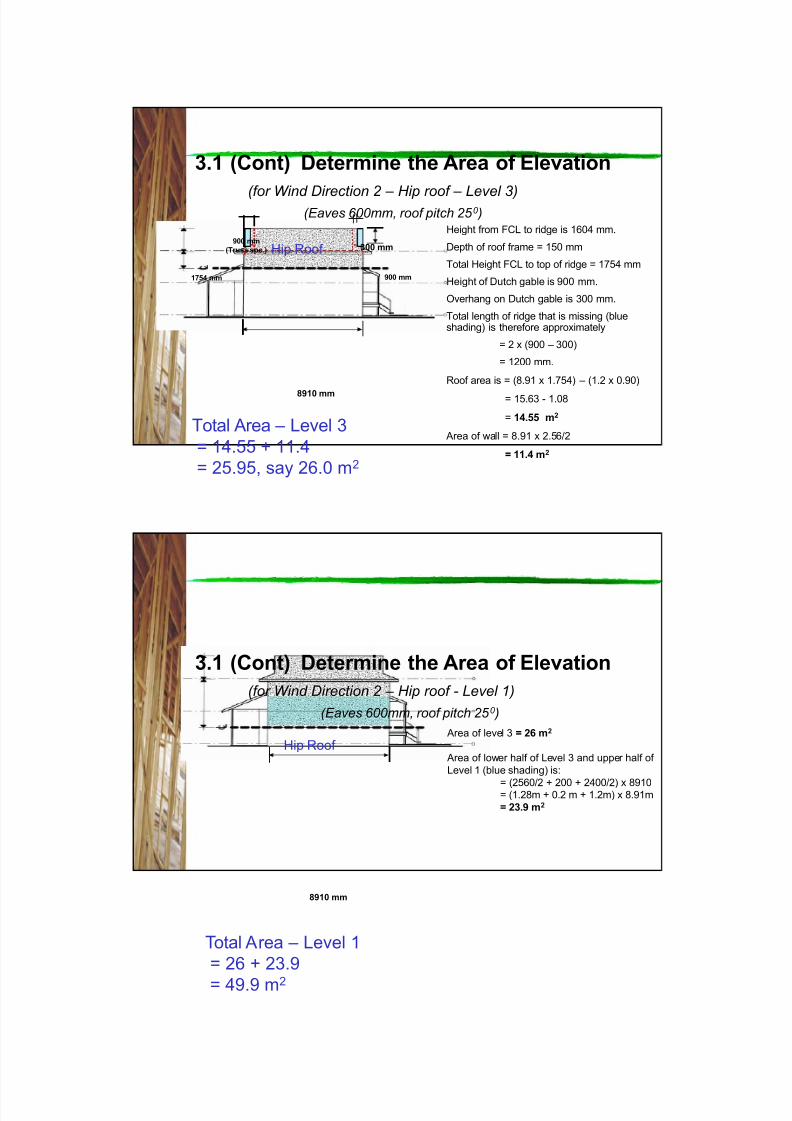
3.1 (Cont) Determine the Area of Elevation
(for Wind Direction 2 –
Hip roof –
Level 3)(Eaves 600mm, roof pitch 25 0 )
8910 mm
Height from FCL to ridge is 1604 mm.
Depth of roof frame = 150 mm
Total Height FCL to top of ridge = 1754 mm
Height of Dutch gable is 900 mm.
Overhang on Dutch gable is 300 mm.
Total length of ridge that is missing (blueshading) is therefore approximately
= 2 x (900 – 300)
= 1200 mm.
Roof area is = (8.91 x 1.754) – (1.2 x 0.90)
= 15.63 - 1.08
= 14.55 m2
Area of wall = 8.91 x 2.56/2
= 11.4 m2
300 mm900 mm
(Truss spc.)
1754 mm 900 mm
Hip Roof
Total Area – Level 1
= 26 + 23.9
= 49.9 m2
3.1 (Cont) Determine the Area of Elevation
(for Wind Direction 2 – Hip roof - Level 1)
(Eaves 600mm, roof pitch 25 0 )
Area of level 3 = 26 m2
Area of lower half of Level 3 and upper half of
Level 1 (blue shading) is:
= (2560/2 + 200 + 2400/2) x 8910= (1.28m + 0.2 m + 1.2m) x 8.91m
= 23.9 m2
8910 mm

8/19/2019 As1684 Split Level c2 House Bracing
http://slidepdf.com/reader/full/as1684-split-level-c2-house-bracing 21/43
21
Hip Roof
Total additional areas – Level 1
= 2.07 + 2.44
= 4.51m2 say 4.5 m2
3.1 (Cont) Determine the Area of Elevation
(for Wind Direction 2 –
Hip roof - Level 1 – additional small areas, shaded blue Eaves 600mm, roof pitch 25 0 )
Front porch assuming one end closed in
approximately
= 3.6/2x 1.15 = 2.07 m2
Rear patio gable, assuming not filled in,
and additional wall area under gableapproximately
= 2.55 x tan25 x 2.55/2 + 0.6 x 1.55
= 1.51 + 0.93
= 2.44 m2
25501150
2600
Note: For the additional areas, the full height of
the wall sections for Level 2 have been used as
the loads are assumed to be shared by both
Levels 1 and 2
Wind direction 2
3.1 (cont) Determine the Area of Elevation
Summary of Areas Direction 1 Direction 2
Level 3
15.3 m2
(gable) Level 326.0 m2
(hip)
Level 1
33.8 m2
(gable)
Level 2
subfloor
31.4 m2
(hip)
Level 2
19.4 m2
(hip)
Level 1 & 2
49.9 m2
(hip)
Level 1 & 2
Additional
areas
4.5 m2
(hip)

8/19/2019 As1684 Split Level c2 House Bracing
http://slidepdf.com/reader/full/as1684-split-level-c2-house-bracing 22/43
22
4. Calculate the racking force
(for both Wind Directions)
Use the formula:
Racking Forc e = Area of Elevat ion x Wind Pressure
(kN) (m 2 ) (kPa) - (kN/m 2 )
For complex elevations, combine the results ofseparate calculations to end up with a total racking
force in each of the two wind directions.
Example: Total racking force for
Wind Direction 2, Levels 1 & 2
Hip = 49.9 m2 x 1.9 kN/m2 = 94.8 kN
Additional areas = 4.5 m
2
x 1.8 kN/m
2
= 8.1 kNTotal = 102.9 kN
4. Calculate the racking force
(for both Wind Direct ions)
Use the formula:
Racking Forc e = Area of Elevat ion x Wind Pressure
(kN) (m 2 ) (kN/m 2 )
Example: Total racking force for:-
Wind Direction 1, Level 2
Hip = 19.4 m2 x 1.7kN/m2 = 32.98, say 33.0 kN
8/19/2019 As1684 Split Level c2 House Bracing
http://slidepdf.com/reader/full/as1684-split-level-c2-house-bracing 23/43
23
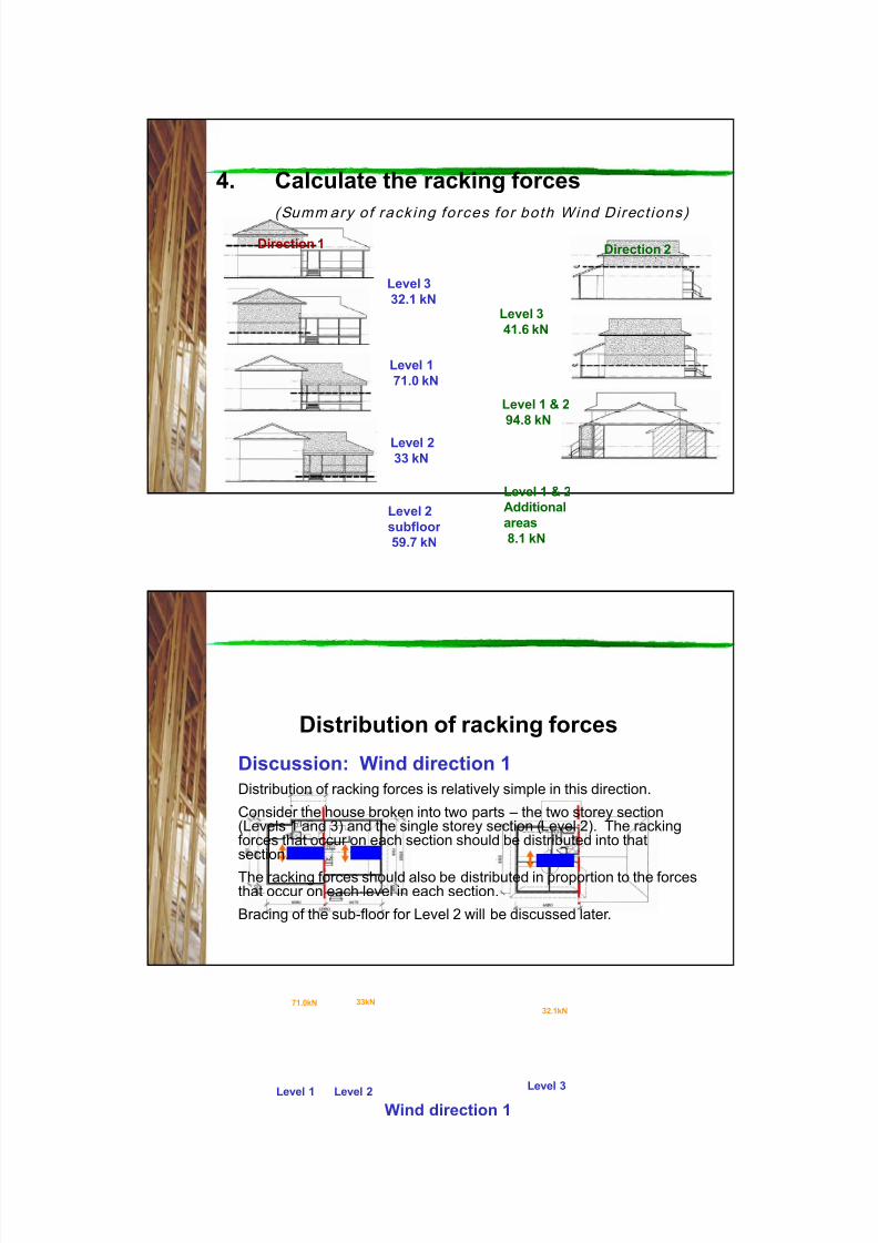
4. Calculate the racking forces
(Summ ary of rack ing forces for both Wind Direct ions)
Direction 1 Direction 2
Level 3
32.1 kNLevel 3
41.6 kN
Level 1
71.0 kN
Level 2
subfloor
59.7 kN
Level 2
33 kN
Level 1 & 2
94.8 kN
Level 1 & 2
Additional
areas
8.1 kN
Distribution of racking forces
Discussion: Wind direction 1
Distribution of racking forces is relatively simple in this direction.
Consider the house broken into two parts – the two storey section(Levels 1 and 3) and the single storey section (Level 2). The rackingforces that occur on each section should be distributed into thatsection.
The racking forces should also be distributed in proportion to the forcesthat occur on each level in each section.
Bracing of the sub-floor for Level 2 will be discussed later.
Wind direction 1Level 1 Level 3Level 2
71.0kN 33kN32.1kN
8/19/2019 As1684 Split Level c2 House Bracing
http://slidepdf.com/reader/full/as1684-split-level-c2-house-bracing 24/43
24
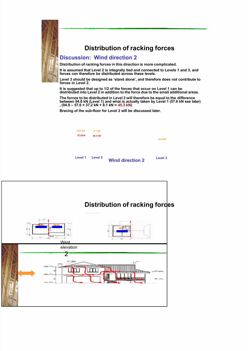
Distribution of racking forces
Discussion: Wind direction 2 Distribution of racking forces in this direction is more complicated.
It is assumed that Level 2 is integrally tied and connected to Levels 1 and 3, andforces can therefore be distributed across these levels.
Level 3 should be designed as ‘stand alone’, and therefore does not contribute toforces in Level 2.
It is suggested that up to 1/2 of the forces that occur on Level 1 can bedistributed into Level 2 in addition to the force due to the small additional areas.
The forces to be distributed in Level 2 will therefore be equal to the differencebetween 94.8 kN (Level 1) and what is actually taken by Level 1 (57.6 kN see later), (94.8 – 57.6 = 37.2 kN + 8.1 kN = 45.3 kN)
Bracing of the sub-floor for Level 2 will be discussed later.
Wind direction 2Level 1 Level 3Level 2
94.8 kN 8.1 kN
41.6 kN
57.6 kN 45.3 kN
Distribution of racking forces
2
West
elevation

8/19/2019 As1684 Split Level c2 House Bracing
http://slidepdf.com/reader/full/as1684-split-level-c2-house-bracing 25/43
25
5. Design the wall bracing systems
Wind direction 1 - Level 1
As the racking force is of a significant
magnitude, relatively strong bracing
walls will be required.
As an initial start, assume bracing walls
will be plywood rated at 6.4kN/m, min
panel length 600 mm (Method A) –
Table 8.18 (h) [pg 140]
Therefore length of bracing wall
required
= 71.0/6.4 = 11.09. say 11.0 m
NOTE: Bracing should initially be
placed in external walls and, where
possible, at the corners of the building –
Clause 8.3.6.6 [pg 148].
71.0 kN
AS1684.3 p140

8/19/2019 As1684 Split Level c2 House Bracing
http://slidepdf.com/reader/full/as1684-split-level-c2-house-bracing 26/43
26
Minimum panel length for Plywoodis 600 mm for Type A bracing
Clause 8.3.6.5(a) [pg 144]
Wall 1.
For LH garage wall, available wall
length is 900 + 600 (corners) +
3600 = 5100 mm
5.1 x 6.4kN/m = 32.6 kN
Wall 2
2 x 1.2 m panels = 2.4 m x 6.4
= 15.4 kN
Wall 3
1 x 0.9 m = 0.9 x 6.4 = 5.7 kNWall 4
Available length is 4.4m but use
4.2 x 6.4 = 26.9 kN
TOTAL = 32.6 + 15.4 + 5.7 + 26.9
= 80.6 kN therefore satisfactory
Note: Wall 3 could be deleted and
still OK.
(1)
(1)
(1)
(2)
(3)
(4)71.0 kN
Wind direction 1 - Level 1
Wind direction 1 - Level 2
33.0 kN
Minimum panel length for Plywood
is 600 mm for Type A bracing
Clause 8.3.6.5(a) [pg 144]
Wall 5.
Length is 2400 mm
2.4 x 6.4 kN/m = 15.4 kN
Wall 6
0.8 m x 6.4 kN/m
= 5.1 kN
Wall 7
1.2 m x 6.4kN/m
= 7.7 kN
Wall 8
1.2 m x 6.4 kN/m
= 7.7 kN
TOTAL = 15.4 + 5.1 + 7.7 + 7.7
= 35.9 kN therefore satisfactory
(5)
(7)
(6)
(8)
8/19/2019 As1684 Split Level c2 House Bracing
http://slidepdf.com/reader/full/as1684-split-level-c2-house-bracing 27/43
27
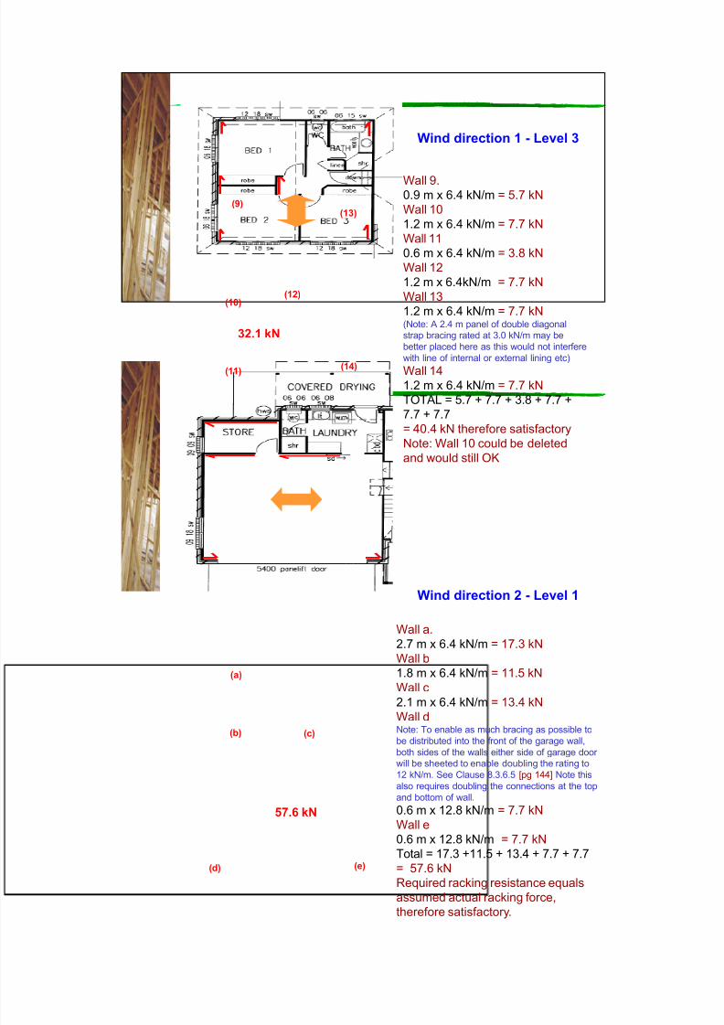
Wind direction 1 - Level 3
32.1 kN
Wall 9.0.9 m x 6.4 kN/m = 5.7 kN
Wall 10
1.2 m x 6.4 kN/m = 7.7 kN
Wall 11
0.6 m x 6.4 kN/m = 3.8 kN
Wall 12
1.2 m x 6.4kN/m = 7.7 kN
Wall 13
1.2 m x 6.4 kN/m = 7.7 kN(Note: A 2.4 m panel of double diagonal
strap bracing rated at 3.0 kN/m may be
better placed here as this would not interfere
with line of internal or external lining etc)Wall 14
1.2 m x 6.4 kN/m = 7.7 kN
TOTAL = 5.7 + 7.7 + 3.8 + 7.7 +
7.7 + 7.7
= 40.4 kN therefore satisfactory
Note: Wall 10 could be deleted
and would still OK
(11)
(13)(9)
(14)
(10)(12)
Wind direction 2 - Level 1
57.6 kN
Wall a.
2.7 m x 6.4 kN/m = 17.3 kN
Wall b
1.8 m x 6.4 kN/m = 11.5 kN
Wall c
2.1 m x 6.4 kN/m = 13.4 kN
Wall dNote: To enable as much bracing as possible to
be distributed into the front of the garage wall,
both sides of the walls either side of garage door
will be sheeted to enable doubling the rating to
12 kN/m. See Clause 8.3.6.5 [pg 144] Note this
also requires doubling the connections at the top
and bottom of wall.
0.6 m x 12.8 kN/m = 7.7 kN
Wall e
0.6 m x 12.8 kN/m = 7.7 kN
Total = 17.3 +11.5 + 13.4 + 7.7 + 7.7
= 57.6 kN
Required racking resistance equals
assumed actual racking force,therefore satisfactory.
(d)
(a)
(e)
(c)(b)

8/19/2019 As1684 Split Level c2 House Bracing
http://slidepdf.com/reader/full/as1684-split-level-c2-house-bracing 28/43
28
Wind direction 2 - Level 2
45.3 kN
Wall f.1.2 m x 6.4 kN/m = 7.7 kN
Wall g
1.2 m x 6.4 kN/m = 7.7 kN
Wall h
2.4 m x 6.4 kN/m = 15.4 kN
Wall i
1.2 m x 6.4 kN/m = 7.7 kN
Wall j
1.2 m x 6.4 kN/m = 7.7 kN
Total = 6 x 7.7
= 46.2 kN therefore OK
(f)
(j)
(g)
(h)
(i)
Wind direction 2 - Level 3
41.6 kN
Wall k.
0.6 m x 6.4 kN/m = 3.8 kN
Wall l
1.2 m x 6.4 kN/m = 7.7 kN
Wall m
2.4 m x 6.4 kN/m = 15.4 kN
Wall n
0.6 m x 6.4 kN/m = 3.8 kN
Wall o
1.2 m x 6.4 kN/m = 7.7 kN
Wall p
0.6 m x 6.4 kN/m = 3.8 kN
Total = 3 x 3.8 + 2 x 7.7 + 15.4
= 42.2 kN therefore OK
(n) (p)
(l)(k)
(m)
(o)
(q)

8/19/2019 As1684 Split Level c2 House Bracing
http://slidepdf.com/reader/full/as1684-split-level-c2-house-bracing 29/43
29
5.3 Nominal wall bracing
Clause 8.3.6.2 [pg 136] permits up to 50% of
required permanent bracing to be provided by
nominal bracing (normal lined walls).
Nominal bracing has not been considered in this
C2 example because for high wind classifications,
it is usually difficult to find any significant lengths
of un-braced wall available to utilize the nominalbracing capacity that may have otherwise been
available.
This example demonstrates this.
Bracing the sub-floor ofDirection 1 - Level 2
1
North
elevation
33.0 kN
59.7 kN
For Level 2, the racking force of 33.0 kN has already been accounted for.
For the sub-floor of Level 2 the racking force required to be resisted in
Direction 1 is 59.7 kN.

8/19/2019 As1684 Split Level c2 House Bracing
http://slidepdf.com/reader/full/as1684-split-level-c2-house-bracing 30/43
30
Bracing the sub-floor ofDirection 2 - Level 2
2
West
elevation
94.8 kN
46.7 kN
57.6 kN45.3 kN
For Level 3, the racking force of 46.7 kN has already been accounted for.For Level 1, 57.6 kN out of a total of 94.8 kN has been accounted for by
bracing in Level 1.
The remainder 37.2 kN plus the additional small area component, 8.1 kN
= Total = 45.3 kN is distributed into Level 2 via the Level 2 ceiling and floor
diaphragms and then into the sub-floor.
TOTAL in Direction 2 for Levels 1 and 2 = 102.9 kN
+ 8.1 kN
Sub-floor bracing
Clause 8.3.5.8 and Table 8.16 [pg 135] provide bracing capacities for
un-reinforced masonry. Min. panel length (l1 or l2) = 900 mm and
minimum total length of panels (l1 or l2) in any one wall 3000 mm
Subfloor of single storeywith brick veneer over
Bracing
Capacity
(kN/m)
3
l1 l2

8/19/2019 As1684 Split Level c2 House Bracing
http://slidepdf.com/reader/full/as1684-split-level-c2-house-bracing 31/43
31
Direction 1
East wall, min panel lengths > 900 ok.
Sum of panel lengths = 7710 - 2400 mm
= 5310 mm
Bracing resistance = 5.3 x 3 kN/m = 15.9 kN
Direction 2
North and South walls
Sum of panel lengths = (2 x 6670) – (900
+2400 + 1800 + 1800) mm
= 6440 mm
Bracing resistance = 6.4 x 3 kN/m = 9.9kN
Total Direction 2 = 19.2 kN
Contribution of un-reinforced masonry
Sub-floor bracing
59.7 kNrequired
45.3 kNrequired
Direction 1
Sub –floor bracing
Direction1
From the preceding, 59.7 – 15.9 = 43.8 kN
is still required to be provided by bracing
stumps or diagonal bracing sets between
stumps.
Direction 2
From the preceding, 45.3 – 19.2 = 26.1 kN
is still required to be provided by bracing
stump or diagonal bracing sets between
stumps.
Six stumps are available to provide
bracing in each direction.
Additional bracing resistance using steel
or timber bracing stumps will be required
to resist the remaining racking forces.
North
8/19/2019 As1684 Split Level c2 House Bracing
http://slidepdf.com/reader/full/as1684-split-level-c2-house-bracing 32/43
32
Sub – floor bracing
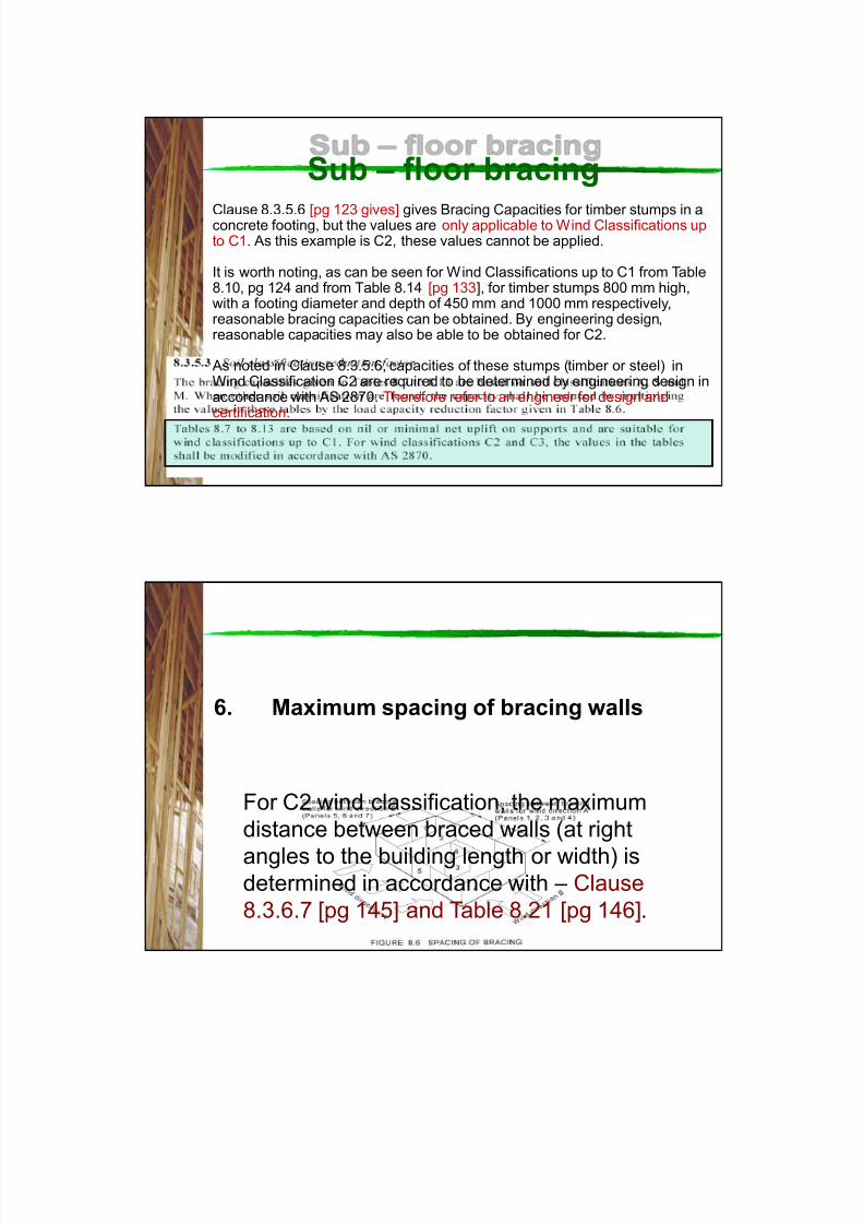
Clause 8.3.5.6 [pg 123 gives] gives Bracing Capacities for timber stumps in aconcrete footing, but the values are only applicable to Wind Classifications upto C1. As this example is C2, these values cannot be applied.
It is worth noting, as can be seen for Wind Classifications up to C1 from Table8.10, pg 124 and from Table 8.14 [pg 133], for timber stumps 800 mm high,with a footing diameter and depth of 450 mm and 1000 mm respectively,reasonable bracing capacities can be obtained. By engineering design,reasonable capacities may also be able to be obtained for C2.
As noted in Clause 8.3.5.6, capacities of these stumps (timber or steel) inWind Classification C2 are required to be determined by engineering design inaccordance with AS 2870. Therefore refer to an engineer for design andcertification.
6. Maximum spacing of bracing walls
For C2 wind classification, the maximum
distance between braced walls (at right
angles to the building length or width) isdetermined in accordance with – Clause
8.3.6.7 [pg 145] and Table 8.21 [pg 146].

8/19/2019 As1684 Split Level c2 House Bracing
http://slidepdf.com/reader/full/as1684-split-level-c2-house-bracing 33/43
33
6. Maximum spacing of bracing walls
Ceiling diaphragm
depth – Direction 1 – Level 2 = 8590 mm
Ceiling diaphragm
depth – Direction 2 –
Level 3 = 6440 mm
Ceiling diaphragm
depth – Direction 1
– Level 3 = 7870 mm
6. Maximum spacing of bracing walls
For Direction 1 – Level 2 – Diaphragm depth = 8590,
Therefore maximum spacing of bracing walls is 5.1 m
8.59 5.1
Interpolation
permitted

8/19/2019 As1684 Split Level c2 House Bracing
http://slidepdf.com/reader/full/as1684-split-level-c2-house-bracing 34/43
34
For Wind direction 1 -
Level 2, the maximum
spacing is 3.6 m which
is less than 5.1 m
therefore satisfactory.
Note: For wind direction
2 for Level 2, maximum
spacing of bracing walls
is not a concern, as this
direction is restrained
by the two-storey
section.
(5)
(7)
(6)
(8)
6 Maximum spacing of Bracing walls
Max spacing
= 3600 mm
Direction 1
6. Maximum spacing of bracing walls
For Direction 1 – Level 3 – Diaphragm depth = 6440,
Therefore maximum spacing of bracing walls is 4.5 m approx.
6.44 4.5
Interpolation
permitted

8/19/2019 As1684 Split Level c2 House Bracing
http://slidepdf.com/reader/full/as1684-split-level-c2-house-bracing 35/43
35
For Wind direction 2 -
Level 3, the maximum
spacing of bracing walls
is 3.6 m which is less
than 4.5 m therefore
satisfactory.
Note: Wind direction 1
for Level 3 also needs to
be checked.
(n) (p)
(l)(k)
(m)
(o)
(q)
Max spacing
= 3600 mm
6. Maximum spacing of bracing walls
Direction 1
6. Maximum spacing of sub-floor bracing
The spacing of bracing in the sub-floor is also
required to be checked Clause 8.3.5.9 [pg 135]
provides details.
As the maximum spacing in C2 is 11 500 mm, for this
example, sub-floor spacing of bracing is not aconcern as actual spacing is considerably less in
both directions

8/19/2019 As1684 Split Level c2 House Bracing
http://slidepdf.com/reader/full/as1684-split-level-c2-house-bracing 36/43
36
Fixing of Bottom of Bracing Walls
The bottom plate of timber-framed bracing
walls shall be fixed at the ends of the bracing
panel and, if required, intermediately to thefloor frame or concrete slab with connections
determined from Table 8.18 (pgs 137 to 143
and Table 8.25 (pgs 152 to 153).
(Clause 8.3.6.10, pg 151)
AS1684.3 p151
7. Connection of bracing - floors

8/19/2019 As1684 Split Level c2 House Bracing
http://slidepdf.com/reader/full/as1684-split-level-c2-house-bracing 37/43
37
AS1684.3 p140
Ceiling diaphragm
7.1 Fixing of Bottom of Bracing Walls
An M12 rod each end
and
a 13 kN capacity
connection
intermediately at 1200
mm maximum
Plywood, Method A – 6.4 kN/m
2560 mm
12.8 kN/m
Note: For double sided
walls @ 12.8 kN/m fixing
requirements are to be
in accordance with
Clause 8.3.6.10, pg 151.
Therefore the tie-down
rods each end are
required to have a
capacity of 2.56 x 12.8 =
32.8 kN
Note: In C2 additional fixings for shear at 900mm Max crs is required – see Table 9.3, pg 161.

8/19/2019 As1684 Split Level c2 House Bracing
http://slidepdf.com/reader/full/as1684-split-level-c2-house-bracing 38/43
38
7.1 Fixing of Bottom of Bracing Walls
From Table 8.25, [pg 152 – 153], some acceptable options
to achieve 13kN assuming JD4 joint group framing are:
Note:
1. For chemical
or other proprietary
fasteners or anchors,
refer to manufacturers
specifications.
2. MGP15 – JD4
MGP12 – JD4
MGP10 – JD5
Fixing of Top of Bracing Walls

8/19/2019 As1684 Split Level c2 House Bracing
http://slidepdf.com/reader/full/as1684-split-level-c2-house-bracing 39/43

8/19/2019 As1684 Split Level c2 House Bracing
http://slidepdf.com/reader/full/as1684-split-level-c2-house-bracing 40/43
40
To determine the correct fixing at the top
plate, look at the (in this case) truss plan.
And….
1. Determine what direction the walls are
running in relation to the trusses.
Roof Trusses
Wall
perpendicular
to roof
trusses
Wall parallel to roof
trusses
7.2 Fixing of Top of Bracing Walls Cont.
Plan view
2. Select an appropriate fixing requirement
from Table 8.23 [pg 148 151]
7.2 Fixing of Top of Bracing Walls Cont.

8/19/2019 As1684 Split Level c2 House Bracing
http://slidepdf.com/reader/full/as1684-split-level-c2-house-bracing 41/43
41
NOTE: Be sure that the total bracing capacity
of that individual wall can be resisted by the
connection.
For a 1.2 m Plywood panel rated at 6.4 kN/m,
the force to be resisted by the connection at
the top of the brace wall is:1.2 m x 6.4 kN/m = 7.7 kN
7.2 Fixing of Top of Bracing Walls Cont.
Connection of braced walls parallel to trusses
JD4
Note: Where MGP10 (JD4) is used for internal frames, alternative fixings
or more frequent fixings would be required ie 2 trimmers/1.2 m panel.
JD5

8/19/2019 As1684 Split Level c2 House Bracing
http://slidepdf.com/reader/full/as1684-split-level-c2-house-bracing 42/43
42
Connection of braced walls perpendicular to trusses
Connection of braced internal walls to external wallsNote: The braced section of internal wall does not have to abut the external wall,
but the top plate must provide a continuous tie to the external wall.
JD4

8/19/2019 As1684 Split Level c2 House Bracing
http://slidepdf.com/reader/full/as1684-split-level-c2-house-bracing 43/43
Nail plate - use in accordance
with manufacturers specifications.
Top plate External wall
Internal bracing
wall
Connection of braced internal wallsabutting external walls - alternative detail
Capacities available from nail-plate manufacturers
Acknowledgement
This educational resource has been prepared as part of theForest & Wood Products Australia
Technical Resources Program – Supporting Timber
Education & Training
Prepared and reviewed by:
Timber Queensland Ltd
TPC Solutions Pty Ltd (Vic)
Place Designs (Qld)