as featured in - gch.ulaval.ca représentatifs... · uv light, which makes up only also, this...
TRANSCRIPT

Registered charity number: 207890
Showcasing research from the Nanomaterials & Photocatalysis
Lab of the Department of Chemical Engineering, Laval
University, Quebec, Canada.
Title: Effi cient hollow double-shell photocatalysts for the
degradation of organic pollutants under visible light and in
darkness
The development of photocatalysts that can work both under
visible light and in darkness remains an important research
target for environmental applications. This report presents
the fi rst synthesis of hollow double-shell H:Pt–WO3/TiO
2–
Au nanospheres that exhibit effi cient degradation of organic
pollutants both under visible light and in darkness. This work
opens a new approach to develop effi cient 24 hour-working
photocatalysts for air purifi cation and waste water treatment.
As featured in:
See Trong-On Do et al., J. Mater. Chem. A, 2016, 4, 4413.
www.rsc.org/MaterialsA

Journal ofMaterials Chemistry A
PAPER
Efficient hollow d
Department of Chemical Engineering, Lava
E-mail: [email protected]; Fax: +1
† Electronic supplementary informa10.1039/c5ta09016d
Cite this: J. Mater. Chem. A, 2016, 4,4413
Received 7th November 2015Accepted 21st December 2015
DOI: 10.1039/c5ta09016d
www.rsc.org/MaterialsA
This journal is © The Royal Society of C
ouble-shell photocatalysts for thedegradation of organic pollutants under visiblelight and in darkness†
Chinh-Chien Nguyen, Nhu-Nang Vu and Trong-On Do*
The development of efficient photocatalysts that can work both under visible light and in darkness remains
an important research target for environmental applications. A large number of photocatalysts have been
reported, but they still suffer from low activity that originates from fundamental efficiency bottlenecks:
i.e., weak photon absorption and poor electron–hole pair separation when operating under irradiation,
and poor electron storage capacity when operating in darkness. Herein, we report the first synthesis of
hollow double-shell H:Pt–WO3/TiO2–Au nanospheres with high specific surface area, large TiO2/WO3
interfacial contact and strong visible light absorption. Because of these features, this type of
nanocomposite shows high charge separation and electron storage capacity, and exhibits efficient
degradation of organic pollutants both under visible light (l $ 420 nm) and in darkness. In addition, CO2
generation from formaldehyde gave a high quantum efficiency of 77.6%.
Introduction
Semiconductor-based photocatalysts are attractive candidatesfor clean energy production and for environmental applica-tions, such as air purication and wastewater treatment. TiO2,one of the most widely used semiconducting metal oxides, hasreceived enormous research interest in the past few decades,due to its exceptional ability to decompose organic pollutants,as well as its corrosion resistance, durability, nontoxicity, andlow cost.1,2 Unfortunately, the application of TiO2 is limited toUV light, which makes up only �4% of the energy of the inci-dent solar spectrum.3,4 To overcome this limitation, researchefforts have been focused on the development of photocatalystswith strong visible-light absorption, which accounts for 43% ofthe energy of the solar spectrum. However, the developedmaterials still suffer from two fundamental drawbacks: weakphoton absorption and poor electron–hole pair separation.5
To overcome the drawbacks of photocatalysts that onlyfunction under light illumination, the development of a photo-catalytic system that can work both under light irradiation andin darkness is urgently required. The underlying concept is thecoupling of a semiconductor (as an electron generator) withanother substance (as an electron acceptor), wherein thesemiconductor provides photo-excited electrons under lightirradiation and the coupled substance receives and stores theelectrons; the stored electrons are subsequently released in
l University, Quebec, G1V 0A8, Canada.
-418-656-5993; Tel: +1-418-656-3774
tion (ESI) available. See DOI:
hemistry 2016
darkness for organic pollutant decomposition.6 Despite severalreports by Fujishima et al. relating to a photocatalyst based onthe WO3/TiO2 heterostructure, few systems exhibiting thedesired functionality have been reported.7–10 As seen in SchemeSI-1,† due to the matching band energy levels, excited electronsfrom the conduction band of TiO2 can be transferred to that ofWO3, wherein the electrons could be stored for reaction indarkness.6,8–10 It should be noted that the minimal WO3/TiO2
heterostructure interface prepared by conventional methodsrestricts both charge separation and electron storage capacity.Also, this system absorbs only UV light, meaning its photo-catalytic activity under visible light and electron charge–discharge behaviour were both poor. Therefore, to use solarenergy more efficiently, photocatalysts that absorb the entiresolar spectrum and possess high electron storage ability mustbe developed.
The use of plasmonic nanoparticles (NPs) and surfacemodication are the main methods that have been proposed toachieve this enhancement.11,12 Au, Ag, and Cu NPs can harvestvisible light through surface plasmon resonance (SPR) toproduce “hot” electrons on their surfaces.13 These “hot” elec-trons can transfer to the neighbouring semiconductor forparticipation in chemical reactions via an interface, therebyenhancing catalyst efficiency.14,15 Of these metal NPs, Au NPsmost strongly absorb visible light and efficiently catalyse thedecomposition of organic pollutants.16 In addition, surfacemodication through hydrogen treatment to introduce oxygenvacancies can create impurity states in forbidden areas of theband structure, leading to improved photoabsorption andelectron storage. Hence, this strategy provides an efficient routeto the development of functional materials.17
J. Mater. Chem. A, 2016, 4, 4413–4419 | 4413

Journal of Materials Chemistry A Paper
Nanocomposite-based hollow structure photocatalysts haverecently attracted much research attention because of theirunique properties, viz. their nanoscale wall thickness, largeinterface between components, which play a critical role inphotogenerated charge transfer, and high porosity within thewalls, which reduces the diffusion length and improves theaccessibility of active sites for the reactants.18,19 Additionally,multiple reections within the hollow cavity enhance the effi-cient use of the light source, leading to the production of morephotogenerated charge carriers.20
In this study, we developed a new type of hollow double-shellphotocatalyst based on our recently developed approach.21,22
This new type of hollow photocatalyst consists of two compo-nents: (i) an electron storage material (Pt–WO3) and (ii) anelectron generator (TiO2–Au); herein, hollow double-shells areformed and two metal NPs (Pt as a co-catalyst and Au as a strongvisible-light SPR absorber) are selectively loaded onto WO3 andTiO2, respectively. This material is then treated with hydrogento enlarge its light absorption spectrum and to create trappingsites that allow electron storage. This type of hollow double-shell nanocomposite has unique properties, such as highspecic surface area, large TiO2/WO3 interfacial contact, strongsunlight absorption, high electron–hole separation, and largeelectron storage capacity. As a result, the prepared materialshowed excellent activity for the degradation of formaldehyde(HCHO), a major indoor air pollutant, under visible light and indarkness.
Results and discussion
The production of this photocatalyst begins with the one-potsynthesis of Pt–WO3/carbon core–shell nanospheres, which aresubsequently coated with titanate nanodisk (TND) titaniaprecursors using a layer-by-layer technique employing poly(-ethyleneimine) (PEI) as a polyelectrolyte.18,23 Due to the nega-tively charged surface of carbonaceous nanospheres (carboncore), the positively charged PEI easily binds to the carbon corevia electrostatic forces, and converts into a positively chargedcore surface.19,24,25 Subsequently, negatively charged TNDs areadsorbed. The layer-by-layer technique combined with theuniform size of TNDs allows the tuning of shell thickness. The
Fig. 1 Schematic illustration of the synthesis of hollow double-shell Hcarbon colloidal spheres, (2) coating with TNDs using a layer-by-layer straand (4) hydrogen treatment at 350 �C for 1 h.
4414 | J. Mater. Chem. A, 2016, 4, 4413–4419
Au precursor (AuCl4�) is then loaded on carbon core@Pt–WO3/
TNDs to produce carbon core@Pt–WO3/TNDs–AuCl4� (see the
Experimental Section in the ESI† for details). In the second step,the carbon cores and other organic compounds are removedfrom the obtained core–shell nanospheres by calcination in airto form hollow Pt–WO3/TiO2–Au nanospheres (namely Pt–WO3/TiO2–Au), which then undergo H2 treatment to afford the H2-treated hollow double-shell Pt–WO3/TiO2–Au nanospheres(denoted as H:Pt–WO3/TiO2–Au), as depicted in Fig. 1 andScheme SI2.†
It is worth noting that the calcination step in the synthesis issignicant, as it generates microporosity in the shells byremoving the carbon core and PEI. This microporositypromotes hydrogen contact with the TiO2 andWO3 surfaces andthereby lowers the required H2 treatment temperature. In thisway, high specic surface area, large TiO2/WO3 interface, strongvisible light absorption, effective charge separation, and highelectron storage capacity can be achieved. To the best of ourknowledge, this is the rst synthesis of this type of hollowdouble-shell H2-treated WO3/TiO2 nanocomposite based oncarbon colloidal spheres combined with the layer-by-layertechnique.
Fig. 2A and B show scanning electron microscopy (SEM)images of the Pt–WO3/TiO2–Au core–shell sample before (A) andaer calcination and subsequent H2 treatment (B). The nano-spheres are quite uniform, with an average diameter of 1 mm. Aslight change in morphology is observed before the carboncolloidal core is removed and aer hydrogen treatment. As seenin Fig. 2B, some broken particles clearly indicate the presence ofthe hollow nanospheres. These might be formed during calci-nation for carbon core removal. The presence of these holes, infact, should be benecial for photocatalysis as they enhance thediffusion of reactants and light through the shell of the hollowspheres (vide infra).26,27 The morphology of the hollow H:Pt–WO3/TiO2–Au sample was further characterized by trans-mission electron microscopy (TEM) (Fig. 2C and D). Hollowspheres of �1 mm in average diameter were observed (Fig. 2C).Moreover, Au NPs with an average size of 22 nm are evenlydistributed on the wall surface of the TiO2 HNSs (Fig. 2D) whilePt NPs are not observed, probably due to the Pt particles beingsmall and highly dispersed in the hollow nanocomposite. The
:Pt–WO3/TiO2–Au nanospheres: (1) one-pot synthesis of Pt–WO3@-tegy followed by Au precursor loading, (3) calcination at 550 �C for 3 h,
This journal is © The Royal Society of Chemistry 2016

Fig. 2 (A and B) SEM images of Pt–WO3/TiO2–Au before and after calcination followed by hydrogen treatment; (C and D) TEM image of thehollow H:Pt–WO3/TiO2–Au; (E) high resolution TEM image of hollow H:Pt–WO3/TiO2–Au; (F) survey spectrum of hollow H:Pt–WO3/TiO2–Au,inset XPS of Au and Pt.
Paper Journal of Materials Chemistry A
thickness of the HNS shell is estimated to be around 80 nm. Thehigh-resolution TEM image (Fig. 2E) shows the lattice fringes ofboth TiO2 and Au, thus indicating the highly crystalline natureof TiO2 and the Au NPs. The lattice fringe with a d-spacing of0.35 nm can be assigned to the (101) lattice plane of anataseTiO2, and the fringe with a d-spacing of 0.25 nm belongs to the(111) lattice plane of Au with a face-centred cubic phase.28
Fig. 2E also shows intimate contact between Au and TiO2. Thisclose contact between the metal and the semiconductor mayenhance charge transfer between them, and consequently the
This journal is © The Royal Society of Chemistry 2016
photocatalytic efficiency.29,30 As seen in Fig. SI-1,† signicantshrinking of the hollow area of H:Pt–WO3 (�500 nm in size)without coated TNDs was observed. Therefore, it should benoted that the coated TNDs play the critical role of maintainingthe spherical shape aer calcination and hydrogen treatment.Fig. 2F shows the X-ray photoelectron spectroscopy (XPS)spectrum of the hollow H:Pt–WO3/TiO2–Au spheres. Thephotoelectron peaks for Ti 2p and W 4d appear clearly atbinding energies of 460 and 248 eV, respectively. As seen in theinset of Fig. 2F, the Pt XPS spectra show two peaks at 71.41 and
J. Mater. Chem. A, 2016, 4, 4413–4419 | 4415

Journal of Materials Chemistry A Paper
74.76 eV attributed to metallic Pt, conrming the presence of Ptin the sample, while the Au 4f XPS spectra exhibit a peak at 84.4eV characteristic of Au0 on TiO2.31 Elemental analysis byinductively coupled plasma mass spectrometry (ICP-MS) revealsthat the Au and Pt loadings are 3.0 and 2.5 wt%, respectively.The H:Pt–WO3/TiO2–Au sample was also analysed by energy-dispersive spectroscopy (EDS), as shown in Fig. SI2.† The EDSspectra clearly show that W and Ti are the main constituentelements and that the atomic W : Ti ratio is around 1 : 1 in thenanocomposite.
The X-ray diffraction pattern of the hollow double-shellH:Pt–WO3/TiO2–Au sample is shown in Fig. 3A, indicating thepresence of WO3, TiO2, and Au in the material; no XRD peakcharacteristic of Pt was detected. As mentioned above, thiscould be due to the small size of the Pt NPs (<5 nm). The WO3
phase is conrmed by the peak at 2q ¼ 23�. The peak at 2q ¼25.2� matches well with the anatase phase of TiO2,32 while thepeak at 38.5� corresponds to the (111) plane of Au.33 Meanwhile,the intensities of the WO3 and TiO2 phases in the XRD patternsare relatively weak because of the NP size and the increase in theWO3/TiO2 interface in the nanocomposite.34–36 Fig. 3B shows theUV-vis absorption spectra of different calcined hollow samplesbefore and aer H2 treatment: hollow Pt–WO3/TiO2 in theabsence of Au, Pt–WO3/TiO2–Au (both before H2 treatment),hollow H:Pt–WO3, hollow H:Pt–WO3/TiO2, and hollow H:Pt–WO3/TiO2–Au (aer H2 treatment). For the samples untreatedwith H2 (Fig. 3B(a and b)), the UV-vis spectra are mostly iden-tical, except for a peak centred at 550 nm that is attributed to the
Fig. 3 (A) Powder XRD spectrum of hollow H:Pt–WO3/TiO2–Au; (B)UV-vis spectra of different samples: (a) hollow Pt–WO3/TiO2, (b)hollow Pt–WO3/TiO2–Au before H2 treatment; (c) hollow H:Pt–WO3/TiO2, (d) hollow H:Pt–WO3/TiO2–Au, and (e) hollow H:Pt–WO3 afterhydrogen treatment; (C and D) XPS Ti 2p and W 4f spectra of Pt–WO3/TiO2–Au before and after H2 treatment.
4416 | J. Mater. Chem. A, 2016, 4, 4413–4419
SPR of Au NPs in the Pt–WO3/TiO2–Au sample.14 Interestingly,aer H2 treatment, all the samples show strong and broad lightabsorption, extending to even the NIR region (Fig. 3B(c–e)).These indicate the full sunlight absorption of these samplesaer H2 treatment, which is in agreement with the colourchange from pink to dark green (Pt–WO3/TiO2 and Pt–WO3/TiO2–Au), and from yellow to black (hollow H:Pt–WO3) aerhydrogen treatment. It should be noted that the presence of PtNPs on WO3 has a signicant impact on reduction by hydrogen.Facile reduction and change in colour of WO3 during H2 treat-ment could be a result of the chemisorption and subsequentdissociation of H2 molecules on the Pt NP surface to very activehydrogen atoms (i.e., hydrogen spillover). These hydrogenatoms then migrate to the WO3 particles, reducing them toblack WO3�x particles.37 In contrast, no signicant change incolour or in the UV-vis spectra was observed for the sampleswithout Pt, neither before nor aer H2 treatment (see Fig. SI-3†for details).
The surface chemical states of Ti and W before and aerhydrogen annealing were characterized by X-ray photoelectronspectroscopy (XPS). Fig. 3C shows the Ti 2p3/2 XPS spectra ofthese samples. The Ti 2p3/2 XPS spectrum of the sample beforeH2 treatment shows two peaks at the binding energies of 458.4eV and 464.1 eV, which are characteristic of Ti4+ in anatase TiO2.The similarities between the obtained Ti 2p3/2 spectra indicatea similar bonding environment aer hydrogen treatment.38,39
TheW 4f XPS spectra of these samples are shown in Fig. 3D. Forthe sample before H2 treatment, only two XPS peaks at 38.4 and36.3 eV were found, which are characteristic of W6+. However,aer H2 treatment, the sample exhibits different oxidationstates for W. Apart from the two main XPS peaks for W6+ at 38.4and 36.3 eV, the appearance of W5+ and W4+ is unambiguouslyobserved in the H2-treated sample. As seen in Fig. 3D, the twopeaks located at 34.5 and 36.4 eV are assigned to W5+, and thetwo peaks centred at 32.1 and 33.5 eV are attributed to W4+
species; small peaks at 32.0 and 34.2 eV characteristic of W3+
were also found. It should be noted that the WO3 chemicalstates could be observed in the as-prepared sample due to thepresence of Pt NPs on the WO3. The dissociation of H2 mole-cules on Pt NPs to form H atoms (hydrogen-spillover) couldreduce W6+, even at mild temperatures.40,41 In contrast, no PtNPs were located on TiO2; furthermore, TiO2 requires severereduction conditions like high pressure and high tempera-ture.42,43 Consequently, a high concentration of oxygen vacan-cies in the WO3�x matrix can be achieved aer H2 treatment;these vacancies act as trapping sites for electron storage in thismaterial (Fig. SI-4†). Moreover, the presence of oxygen vacanciesis demonstrated by improved visible/NIR absorption, indicatingthe introduction of impurity states into the forbidden areas ofthe WO3 band structure below the conduction band and a cor-responding reduction in excitation energy. Solar harvesting,therefore, is signicantly improved.44,45
The porous structures of the different samples were char-acterized using N2 physical adsorption at 77 K. The specicsurface area of our hollow double-shell H:Pt–WO3/TiO2–Aunanocomposite reaches 220 m2 g�1, which is much higher thanthat of conventional porous TiO2–P25 (50 m2 g�1), WO3 (8 m2
This journal is © The Royal Society of Chemistry 2016
Paper Journal of Materials Chemistry A
g�1), andmixed TiO2–WO3 (17 m2 g�1) (Table SI-1†). As far as we
know, this nanocomposite has a higher surface area than anyother WO3/TiO2 material that has been reported.46
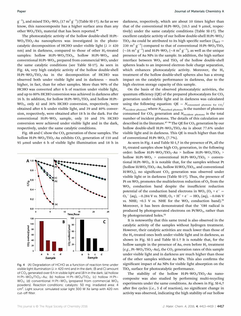
The photocatalytic activity of the hollow double-shell H:Pt–WO3/TiO2–Au nanospheres was investigated in the photo-catalytic decomposition of HCHO under visible light (l $ 420nm) and in darkness, compared to those of other H2-treatedsamples: hollow H:Pt–WO3/TiO2, hollow H:Pt–WO3, andconventional H:Pt–WO3, prepared from commercial WO3 underthe same catalytic conditions (see Table SI-1†). As seen inFig. 4A, very high catalytic activity of the hollow double-shellH:Pt–WO3/TiO2–Au in the decomposition of HCHO wasobserved both under visible light and in darkness – muchhigher, in fact, than for other samples. More than 90% of theHCHO was converted aer 6 h of reaction under visible light,and up to 80%HCHO conversion was achieved in darkness aer16 h. In addition, for hollow H:Pt–WO3/TiO2 and hollow H:Pt–WO3, only 42 and 36% HCHO conversion, respectively, wereobtained aer 6 h under visible light, and 39 and 40% conver-sion, respectively, were obtained aer 18 h in the dark. For theconventional H:Pt–WO3 sample, only 10 and 5% HCHOconversion were achieved under visible light and in the dark,respectively, under the same catalytic conditions.
Fig. 4B and C show the CO2 generation of these samples. Thehollow H:Pt–WO3/TiO2–Au exhibits CO2 generation of 110 and95 mmol under 6 h of visible light illumination and 18 h in
Fig. 4 (A) Degradation of HCHO as a function of reaction time undervisible light illumination (l$ 420 nm) and in the dark; (B and C) amountof CO2 generated over 6 h in visible light and 18 h in the dark; (a) hollowH:Pt–WO3/TiO2–Au; (b) hollow H:Pt–WO3/TiO2; (c) hollow H:Pt–WO3; (d) conventional H:Pt–WO3 (prepared from commercial WO3
powders). Reaction conditions: catalysts: 50 mg; irradiated area: 4cm2. Light source: simulated solar light 300 W Xe lamp with 420 nmcut-off filter.
This journal is © The Royal Society of Chemistry 2016
darkness, respectively, which are about 10 times higher thanthat of the conventional H:Pt–WO3 (10.5 and 9 mmol, respec-tively) under the same catalytic conditions (Table SI-1†). Theexcellent catalytic activity of our hollow double-shell H:Pt–WO3/TiO2–Au could be attributed to its high specic surface (SBET ¼230 m2 g�1) compared to that of conventional H:Pt–WO3/TiO2
(�16 m2 g�1) and H:Pt–WO3 (�8 m2 g�1), as well as the uniquepresence of Au NPs in the sample. In addition, the high surfaceinterface between WO3 and TiO2 of the hollow double-shellspheres leads to an improved electron–hole charge separation,which enhances photocatalytic activity. Moreover, the H2
treatment of the hollow double-shell spheres also has a strongimpact on the catalytic performance in darkness, due to thehigh electron storage capacity of this sample.
On the basis of the observed photocatalytic activities, thequantum efficiency (QE) of the prepared photocatalysts for CO2
generation under visible light and in darkness was calculatedusing the following equation: QE ¼ Nconsumed photons for CO2
/Nincident photons; where Nabsorbed photons is the number of photonsconsumed for CO2 generation and Nincident photons is the totalnumber of incident photons. The details of this calculation aredescribed in the literature.47–50 The QE for CO2 generation by ourhollow double-shell H:Pt–WO3/TiO2–Au is about 77.6% undervisible light and in darkness. This QE is much higher than thatof conventional H:Pt–WO3 (7.7%).
As seen in Fig. 4 and Table SI-1,† in the presence of Pt, all theH2-treated samples show high CO2 generation, in the followingorder: hollow H:Pt–WO3/TiO2–Au > hollow H:Pt–WO3/TiO2 >hollow H:Pt–WO3 > conventional H:Pt–WO3/TiO2 > conven-tional H:Pt–WO3. It is notable that, for the samples without Pt(hollow H:WO3/TiO2–Au, hollow H:WO3/TiO2, and conventionalH:WO3), no signicant CO2 generation was observed undervisible light or in darkness (Table SI-1†). Thus, the presence ofPt on WO3 promotes the multielectron reduction of O2 from theWO3 conduction band despite the insufficient reductionpotential of the conduction band electrons in WO3 (O2 + e� ¼O2
� (aq), �0.284 V vs. NHE; O2 + H+ + e� ¼ HO2 (aq), �0.046 Vvs. NHE; +0.5 V vs. NHE for the WO3 conduction band).51
Moreover, it has been demonstrated that the cOH radical isproduced by photogenerated electrons on Pt/WO3, rather thanby photogenerated holes.52
It is noteworthy that this same trend is also observed in thecatalytic activity of the samples without hydrogen treatment.However, their catalytic activities are much lower than those ofthe H2-treated ones both under visible light and in darkness, asshown in Fig. SI-5 and Table SI-1.† It is notable that, for thehollow sample in the presence of Au, even before H2 treatment(e.g., Pt–WO3/TiO2–Au), the CO2 generation rates of this sampleunder visible light and in darkness are much higher than thoseof the other samples without Au NPs. This also conrms thesignicant impact of Au NPs for visible light absorption on theTiO2 surface for photocatalytic performance.
The stability of the hollow H:Pt–WO3/TiO2–Au nano-composite was also studied by performing multi-recyclingexperiments under the same conditions. As shown in Fig. SI-6,†aer ve cycles (i.e., 5 d of reaction), no signicant change inactivity was observed, indicating the high stability of our hollow
J. Mater. Chem. A, 2016, 4, 4413–4419 | 4417

Fig. 5 Schematic illustration of the catalytic mechanism of the hollowdouble-shell H:Pt–WO3/TiO2–Au photocatalyst under visible lightirradiation and in darkness.
Journal of Materials Chemistry A Paper
photocatalyst in the decomposition of organic pollutants. Asshown in Fig. SI-7A,† the morphology of the as-prepared samplewas retained aer ve cycles. Also, no change in XRD patterns(Fig. SI-7B†) could be observed for the recycled samples. Theseresults reveal that effective sunlight absorption and high chargecarrier separation are required for efficient visible-light-drivenphotocatalysts. Also, catalytic activity in the dark depends ona number of oxygen vacancies in the WO3�x matrix (Fig. SI4†),which can store electrons under light irradiation and dischargethem in darkness via Pt NPs (as active sites) for degradation oforganic pollutants.8 Therefore, the excellent catalytic activity ofour hollow double-shell H:Pt–WO3/TiO2–Au nanospheres undervisible light and in darkness could be associated with four mainfactors: Pt on WO3–x, high interfacial contact between WO3–x
and TiO2 and specic surface area, SPR induced by Au NPs inTiO2, and oxygen vacancies in the WO3�x matrix.43
On the basis of these results, we propose a possible mecha-nism to explain the excellent photoactivity of our hollow double-shell photocomposite, as described in Fig. 5 and SI-8.† Ourhollow H:Pt–WO3/TiO2–Au exhibits excellent performance inthe degradation of HCHO. This is due to the synergetic impactof several factors. Under visible light illumination, Au NPs canharvest visible light through SPR to produce “hot” electrons attheir surfaces. At the same time, electrons can be produced inthe WO3�x conduction band through band gap excitation.Because of suitable energy levels, the “hot” electrons are injec-ted into the TiO2 conduction band and then into the WO3�x
matrix. The photogenerated electrons can be stored in thetrapping sites induced by the large amount of oxygen vacanciesand simultaneously transferred to the Pt NPs for chemicalreactions. In the dark, stored electrons are released andattracted by Pt NPs for the decomposition of organiccompounds (Fig. 5 and SI-8†).
Conclusion
In summary, we have successfully prepared a new type of hollowdouble-shell H:Pt–WO3/TiO2–Au nanosphere using carboncolloidal spheres as the sacricial template. The obtainedphotocatalyst showed excellent catalytic activity for thedecomposition of HCHO under visible light and in darkness.
4418 | J. Mater. Chem. A, 2016, 4, 4413–4419
The enhancement in catalytic activity of this new type of hollowdouble-shell photocatalyst can be associated with the synergiccontributions of Pt NPs as a co-catalyst, the high surface areaand TiO2/WO3 interfacial contact, plasmonic resonance effectsinduced by Au NPs, and a large number of oxygen vacancies inthe WO3�x matrix. This type of hollow material was reasonablystable under catalytic conditions, and hence, has real potentialfor air/water degradation both under visible-light illuminationand in darkness. Work is in progress to gain further insight intothe mechanistic aspects of this process. Furthermore, thisstrategy can be extended to other hollow double-shell nano-composite systems for various applications.
Experimental section
Details about chemicals, synthesis of materials, characteriza-tion methods, and photocatalytic tests are available in the ESI.†
Acknowledgements
This work was supported by the Natural Science and Engi-neering Research Council of Canada (NSERC) through theCollaborative Research and Development with EXP Inc. (CRD)and Discovery Grants. We thank Dr Thanh-Dinh Nguyen forsimulating discussion and comments.
Notes and references
1 A. Fujishima and K. Honda, Nature, 1972, 238, 37–38.2 M. Wang, J. Ioccozia, L. Sun, C. Lin and Z. Lin, EnergyEnviron. Sci., 2014, 7, 2182–2202.
3 F. Fresno, R. Portela, S. Suarez and J. M. Coronado, J. Mater.Chem. A, 2014, 2, 2863–2884.
4 H. Wang, L. Zhang, Z. Chen, J. Hu, S. Li, Z. Wang, J. Liu andX. Wang, Chem. Soc. Rev., 2014, 43, 5234–5244.
5 M. R. Gholipour, C.-T. Dinh, F. Beland and T.-O. Do,Nanoscale, 2015, 7, 8187–8208.
6 D. Su, J. Wang, Y. Tang, C. Liu, L. Liu and X. Han, Chem.Commun., 2011, 47, 4231–4233.
7 T. Tatsuma, S. Saitoh, Y. Ohko and A. Fujishima, Chem.Mater., 2001, 13, 2838–2842.
8 T. Tatsuma, S. Saitoh, P. Ngaotrakanwiwat, Y. Ohko andA. Fujishima, Langmuir, 2002, 18, 7777–7779.
9 P. Ngaotrakanwiwat, T. Tatsuma, S. Saitoh, Y. Ohko andA. Fujishima, Phys. Chem. Chem. Phys., 2003, 5, 3234–3237.
10 T. Tatsuma, S. Takeda, S. Saitoh, Y. Ohko and A. Fujishima,Electrochem. Commun., 2003, 5, 793–796.
11 S. Bai, J. Jiang, Q. Zhang and Y. Xiong, Chem. Soc. Rev., 2015,44, 2893–2939.
12 S. K. Dutta, S. K. Mehetor and N. Pradhan, J. Phys. Chem.Lett., 2015, 6, 936–944.
13 P. Christopher, H. Xin and S. Linic, Nat. Chem., 2011, 3, 467–472.
14 S. Linic, U. Aslam, C. Boerigter andM. Morabito, Nat. Mater.,2015, 14, 567–576.
15 J. Y. Park, L. R. Baker and G. A. Somorjai, Chem. Rev., 2015,115, 2781–2817.
This journal is © The Royal Society of Chemistry 2016

Paper Journal of Materials Chemistry A
16 S. Sarina, E. R. Waclawik and H. Zhu, Green Chem., 2013, 15,1814–1833.
17 X. Sun, Y. Guo, C. Wu and Y. Xie, Adv. Mater., 2015, 27, 3850–3867.
18 S. Wang, H. Qian, Y. Hu, W. Dai, Y. Zhong, J. Chen andX. Hu, Dalton Trans., 2013, 42, 1122–1128.
19 Y. Liu, L. Yu, Y. Hu, C. Guo, F. Zhang and X. Wen Lou,Nanoscale, 2012, 4, 183–187.
20 C. C. Nguyen, N. N. Vu and T.-O. Do, J. Mater. Chem. A, 2015,3, 18345–18359.
21 C.-T. Dinh, M.-H. Pham, Y. Seo, F. Kleitz and T.-O. Do,Nanoscale, 2014, 6, 4819–4829.
22 M.-H. Pham, C.-T. Dinh, G.-T. Vuong, N.-D. Ta and T.-O. Do,Phys. Chem. Chem. Phys., 2014, 16, 5937–5941.
23 C.-T. Dinh, Y. Seo, T.-D. Nguyen, F. Kleitz and T.-O. Do,Angew. Chem., Int. Ed., 2012, 51, 6608–6612.
24 X. Sun and Y. Li, Angew. Chem., Int. Ed., 2004, 43, 3827–3831.25 X. Sun and Y. Li, Angew. Chem., Int. Ed., 2004, 43, 597–601.26 J. B. Joo, Q. Zhang, I. Lee, M. Dahl, F. Zaera and Y. Yin, Adv.
Funct. Mater., 2012, 22, 166–174.27 H. Li, Z. Bian, J. Zhu, D. Zhang, G. Li, Y. Huo, H. Li and Y. Lu,
J. Am. Chem. Soc., 2007, 129, 8406–8407.28 C.-T. Dinh, H. Yen, F. Kleitz and T.-O. Do, Angew. Chem., Int.
Ed., 2014, 53, 6618–6623.29 D. Ding, K. Liu, S. He, C. Gao and Y. Yin, Nano Lett., 2014, 14,
6731–6736.30 S. J. Moniz, S. A. Shevlin, D. J. Martin, Z.-X. Guo and J. Tang,
Energy Environ. Sci., 2015, 8, 731–759.31 M. P. Casaletto, A. Longo, A. Martorana, A. Prestianni and
A. M. Venezia, Surf. Interface Anal., 2006, 38, 215–218.32 H. G. Yang, C. H. Sun, S. Z. Qiao, J. Zou, G. Liu, S. C. Smith,
H. M. Cheng and G. Q. Lu, Nature, 2008, 453, 638–641.33 K. B. Narayanan and N. Sakthivel, Mater. Lett., 2008, 62,
4588–4590.34 X.-L. Li, T.-J. Lou, X.-M. Sun and Y.-D. Li, Inorg. Chem., 2004,
43, 5442–5449.
This journal is © The Royal Society of Chemistry 2016
35 N. Serpone, D. Lawless and R. Khairutdinov, J. Phys. Chem.,1995, 99, 16646–16654.
36 L. Cheng, X. Zhang, B. Liu, H. Wang, Y. Li, Y. Huang andZ. Du, Nanotechnology, 2005, 16, 1341.
37 W. C. Conner and J. L. Falconer, Chem. Rev., 1995, 95, 759–788.
38 J.-Y. Eom, S.-J. Lim, S.-M. Lee, W.-H. Ryu and H.-S. Kwon, J.Mater. Chem. A, 2015, 3, 11183–11188.
39 T.-D. Nguyen-Phan, S. Luo, Z. Liu, A. D. Gamalski, J. Tao,W. Xu, E. A. Stach, D. E. Polyansky, S. D. Senanayake andE. Fujita, Chem. Mater., 2015, 27, 6282–6296.
40 S. Khoobiar, J. Phys. Chem., 1964, 68, 411–412.41 R. Prins, Chem. Rev., 2012, 112, 2714–2738.42 X. Yu, B. Kim and Y. K. Kim, ACS Catal., 2013, 3, 2479–2486.43 X. Chen, L. Liu, P. Y. Yu and S. S. Mao, Science, 2011, 331,
746–750.44 R. Wu, J. Zhang, Y. Shi, D. Liu and B. Zhang, J. Am. Chem.
Soc., 2015, 137, 6983–6986.45 J. Yan, T. Wang, G. Wu, W. Dai, N. Guan, L. Li and J. Gong,
Adv. Mater., 2015, 27, 1580–1586.46 G. Puma, Chem. Commun., 2007, 4749–4751.47 M. Liu, X. Qiu, M. Miyauchi and K. Hashimoto, J. Am. Chem.
Soc., 2013, 135, 10064–10072.48 M. Liu, R. Inde, M. Nishikawa, X. Qiu, D. Atarashi, E. Sakai,
Y. Nosaka, K. Hashimoto and M. Miyauchi, ACS Nano, 2014,8, 7229–7238.
49 J. M. Buriak, P. V. Kamat and K. S. Schanze, ACS Appl. Mater.Interfaces, 2014, 6, 11815–11816.
50 H. Kisch and D. Bahnemann, J. Phys. Chem. Lett., 2015, 6,1907–1910.
51 R. Abe, H. Takami, N. Murakami and B. Ohtani, J. Am. Chem.Soc., 2008, 130, 7780–7781.
52 J. Kim, C. W. Lee and W. Choi, Energy Environ. Sci., 2010, 44,6849–6854.
J. Mater. Chem. A, 2016, 4, 4413–4419 | 4419

1
Supporting Information
Efficient hollow double-shell photocatalysts for the degradation of organic pollutants under visible light and in darkness
Chinh- Chien Nguyen, Nhu- Nang Vu, and Trong- On Do*
Experimental Section
Chemicals
Sucrose, sodium tungstate, hexachloroplatinic acid hexahydrate, titanium butoxide (TB), benzyl alcohol (BA),
oleylamine (OM), benzyl ether, tetraethylammonium hydroxide (TEAOH), polyethyleneimine (PEI),
ammonium hydroxide, and tetrachloroauric(III) acid were purchased from Aldrich. All of the reagents were
used without further purification.
Synthesis of carbon colloidal spheres@Pt-WO3:
Typically, 32 g sucrose was dissolved in 160 mL deionized water. Then, 0.5 g Na2WO4 and 2 g of a 1 mg
mL−1 H2PtCl6 aqueous solution was added to the above solution, which was then heated in a Teflon-lined
autoclave at 160 °C for 6 h. Afterwards, the solid product was collected by centrifugation at 6000 ppm for 10
min, washed several times with water and ethanol, and dried overnight at 80 °C.
Synthesis of titanate nanodisks (TNDs):
The synthesis of water-soluble TNDs was based on our previous studies. Briefly, 2g of TB, 12 g of OM,
12g of BA, and 30g of benzyl ether were added to a 100-mL round-bottom flask. The reaction mixture was
heated to 190 °C at the heating rate 5 °C/min under nitrogen flow. After 20 h, the reaction was cooled to
room temperature. After addition of excess absolute ethanol, the TNDs were recovered and were subjected
to three cycles of dispersion in toluene and re-precipitation with ethanol. Then, the as-synthesised TNDs
were treated with a mixture of TEAOH (15 mmol), ethanol (15 ml), and water (15 ml). The mixture was
stirred overnight at room temperature followed by adding of acetone to obtain precipitate TNDs.
Afterwards, the precipitate was washed several times with acetone and finally dispersed in 100 mL of water.
Synthesis of Carbon colloidal spheres@Pt-WO3/TNDs-AuCl4-
As-prepared carbon colloidal spheres@Pt-WO3 were coated with TNDs using a layer-by-layer deposition
technique (see Scheme SI 2). The carbon colloidal spheres@Pt-WO3 (2 g) was dispersed in 50 mL of
deionized water containing 0.3 g PEI and stirred for 1 h to ensure the saturated adsorption of PEI on the
surface of the carbon spheres. Excess PEI was removed by centrifugation before being subjected to 50 mL of
H2O containing 50 mg TNDs under stirring. The electrostatic force between the negatively charged TNDs and
positively charged PEI on the surface of carbon spheres obtains a layer of TNDs on the surface of carbon
spheres. The resulting material was then recovered by centrifugation and washing. The above procedure
was repeated for seven cycles to obtain the carbon colloidal spheres@Pt-WO3/TNDs. Then, as-prepared
carbon colloidal spheres@Pt-WO3/TNDs was re-dispersed in 50 mL of HAuCl4 solution (15 mM). The resulting
mixture was stirred for 1 h to ensure the adsorption of AuCl4− on the carbon colloidal spheres@Pt-
WO3/TNDs. After that the precipitate was collected by centrifugation, dried at 70 °C overnight and calcined
at 550 °C for 3 h to obtain hollow double-shell Pt-WO3/TiO2-Au.
Hydrogen treatment
The calcined hollow double-shell Pt-WO3/TiO2-Au spheres (100 mg) were put into a ceramic boat and
treated in a hydrogen atmosphere (95% in Argon) in a tube furnace at 350 °C at a flow rate 200 mL min−1 for
1 h to obtain hollow double-shell H2-treated Pt-WO3/TiO2-Au spheres (denoted as H: Pt-WO3/TiO2-Au).
Characterisation
TEM images of the samples were obtained on a JOEL JEM 1230 operated at 120 kV. High-resolution TEM
(HRTEM) images were obtained on Philips G2 F30 Tecnai instrument operated at 300 kV. SEM images were

2
obtained on a JEOL 6360 instrument operated at 15 kV. Powder XRD patterns of the samples were obtained
on a Bruker SMART APEXII X-ray diffractometer equipped with a Cu Kα radiation source (λ = 1.5418 Å). XPS
measurements were carried out in an ion-pumped chamber (evacuated to 10−9Torr) of a photoelectron
spectrometer (Kratos Axis-Ultra) equipped with a focused X-ray source (Al Kα, hν = 1486.6 eV). The UV-vis
spectra were recorded on a Cary 300 Bio UV-visible spectrophotometer. N2 adsorption–desorption
isotherms of the samples were obtained at −196 °C using Quantachrome Autosorb-1 MP analyser. Before
the measurements, the samples were outgassed under vacuum for 6 h at 120 °C.
Catalytic test
Photocatalytic decomposition of formaldehyde: The photocatalytic reactions were conducted in a home-built
top-irradiated reactor (~250 cm3) at ambient temperature and atmospheric pressure. For this photocatalytic
reactor system, the optimum amount of photocatalysts according to our hollow type of nanocomposites was done
to be 50 mg.1 In a typical photocatalytic experiment, an optimized amount of photocatalyst (50 mg) was spread
uniformly in a Petri dish with an inner diameter of 2.2 cm and placed at the bottom of the reactor. The reaction
cell was then evacuated, and filled with fresh synthetic air. Then, a certain amount of condensed formaldehyde
solution (37%) was injected into the reactor. Prior to light irradiation, the reaction cell was kept in the dark for four
hours to ensure that an adsorption–desorption equilibrium of the reactant was established on the surface of the
photocatalysts. Then, the reactor was illuminated with visible light (λ ≥ 420 nm) through a cut-off filter from a
solar simulator 300-W Xe lamp, for six hours. Light intensity was measured by a light radiometer (Newport).
Afterwards, the reaction cell was evacuated, filled with fresh synthetic air before injecting a certain amount of
condensed formaldehyde solution, and was kept in the dark for 18 h. The initial concentration of HCHO vapour
after adsorption/desorption equilibrium was controlled at about 130±5 µmol. Formaldehyde concentration in the
reactor was conducted on-line with a HCHO monitor (Photoacoustic Gas Monitor INNOVA 1412i). Amounts of CO2
gas generated under visible illumination and in darkness were analysed by a gas chromatograph (Agilent 7820A)
equipped with a thermal conductivity detector (TCD) with carboxen-1010 capillary column and He as the gas
carrier.
Quantum efficiency (QE) calculation
The calculation of quantum efficiency (QE) was conducted using the same procedure reported in the
literature.1, 2
Under the visible light irradiation, the wavelength of visible light is from 420 to 700 nm, and the
number of incident photons by integration of intensity at each wavelength is 7.4x10¹⁵
photon.s-1
cm-2
. The
irradiating area is 4 cm2. The optimized irradiation time is 6 hours. Therefore, the number of incident photons for
6h was calculated by using the following equations:
Nincident photons = 7.4x1015
x4x6x3600=6.393x10²⁰
photons.
For CO2 generation, assuming that the reactions from HCHO to CO2 are proceeded on hollow double shell H:Pt-
WO3/TiO2-Au as: HCHO+O2+4H++4e- → CO2 + 3H2O (2e
-CB + O2 + 2H
+ → H2O2; HCHO + 2H2O2 → CO2 + 3H2O); 2H2O +
4h+
→ O2 + 4H+
.3-6
Thus, four photons are required to produce one CO2 molecule. nCO2 was determined to be 110
μmol and 96 μmol under visible irradiation and darkness, respectively. Therefore, the number of photons
consumed to produce CO2 molecules both under 6 hours of light illumination and 18 hours in darkness:
Nconsumed photons for CO2 = 4 x (110 +96) x 10-6
x 6.023x1023
= 49.62 x 10¹⁹
QE = Nconsumed photons for CO2/Nincident photons = (49.62x10¹⁹
/6.393x1020
) x 100 = 77.6%
References
1. M. Liu, X. Qiu, M. Miyauchi and K. Hashimoto, Journal of the American Chemical Society, 2013, 135, 10064-10072. 2. M. Liu, R. Inde, M. Nishikawa, X. Qiu, D. Atarashi, E. Sakai, Y. Nosaka, K. Hashimoto and M. Miyauchi, ACS nano, 2014, 8,
7229-7238. 3. J. Kim, C. W. Lee and W. Choi, Environmental science & technology, 2010, 44, 6849-6854. 4. M. Pelaez, N. T. Nolan, S. C. Pillai, M. K. Seery, P. Falaras, A. G. Kontos, P. S. Dunlop, J. W. Hamilton, J. A. Byrne and K.
O'Shea, Applied Catalysis B: Environmental, 2012, 125, 331-349. 5. L. G. Devi and R. Kavitha, Applied Catalysis B: Environmental, 2013, 140–141, 559-587. 6. P. Ngaotrakanwiwat, T. Tatsuma, S. Saitoh, Y. Ohko and A. Fujishima, Physical Chemistry Chemical Physics, 2003, 5,
3234-3237.

3
Scheme SI-1. Illustration of conventional WO3/TiO2 nanocomposite under UV illumination and in
darkness; the catalytic activity depends on UV irradiation and interfacial contact between WO3 and
TiO2, whereas the activity in darkness is effected by electron transfer from TiO2 and oxygen vacancies
in the WO3 structure. For these reasons, this conventional nanocomposite shows low activity under
visible irradiation and in the dark.
CO2, H2O e e e
e-
e e e
e
HCHO
CO2, H2O
HCHO
UV light
WO3 TiO2 WO3 TiO2
Charging- UV illumination Discharging- In the dark
CB
CB
VB VB VB VB
CB
CB
-
+

4
Scheme SI 2. Illustration of TNDs coated on carbon spheres@ Pt-WO3 using layer-by-layer technique
PEI (Positively charged)
TNDs (Negatively charged surface)
PEI-AuCl4-
Carbon core @Pt-WO3
Carbon core @Pt-WO3/TND-PEI-AuCl4-

5
Figure SI 1. SEM of the hollow H:Pt-WO3 nanospheres
Figure SI 2. EDS of hollow H:Pt-WO3/TiO2-Au spheres confirms the presence of Pt, W, Ti, and Au in
the sample.
1 μm

6
Figure SI 3. UV-Visible spectra of different samples in the absence of Pt before and after H2
treatment; It should be noted that no significant improvement in light absorption occurs before and
after H2 treatment.
Wavelength (nm)
200 300 400 500 600 700 800
Ab
so
rba
nc
e (
a.u
.)
200 300 400 500 600 700 800
Wave length (nm)
200 300 400 500 600 700 800
Ab
so
rba
nc
e (
a.u
.)
200 300 400 500 600 700 800
Ab
so
rba
nc
e (
a.u
.)
Wavelength (nm) Wavelength (nm)
Ab
so
rba
nc
e (
a.u
.)
A B
C D
Hollow WO3/TiO2-Au
Hollow H:WO3/TiO2-Au
Hollow TiO2
Hollow H:TiO2
Hollow WO3
Hollow H:WO3
Hollow WO3/TiO2
Hollow H:WO3/TiO2

7
Figure SI 4. Illustration of oxygen vacancies in the WO3 structure after H2 treatment enhancing light
absorption and electron storage capacity.

8
Figure SI 5. CO2 generation rates of the samples under visible illumination (red colour) and in
darkness (black colour) before hydrogen treatment (A and B) (1) hollow Pt-WO3/TiO2-Au spheres; (2)
hollow Pt-WO3/TiO2; (3) hollow Pt-WO3; (4) conventional Pt-WO3/TiO2, prepared from commercial
WO3 and TiO2-P25, (5) conventional Pt-WO3 prepared from commercial WO3.
1 2 3 4 5
CO
2 e
vo
lve
d (
µm
ol)
0
20
40
60
80
1 2 3 4 5
CO
2 e
vo
lve
d (
µm
ol)
0
10
20
30
40
50
60
70
Sample Sample
A B

9
Figure SI 6. Catalytic stability of hollow H2-treated Pt-WO3/TiO2-Au nanospheres for degradation of
formaldehyde over five cycles under visible light and in darkness.
Cycle 1
Time (hour)
0 5 10 15 20 25
C/C
0
0.0
0.2
0.4
0.6
0.8
1.0
Cycle 2
Time (hour)
0 5 10 15 20 25
Cycle 5
Time (hour)
0 5 10 15 20 25
Visible In dark Visible In dark Visible In dark
10
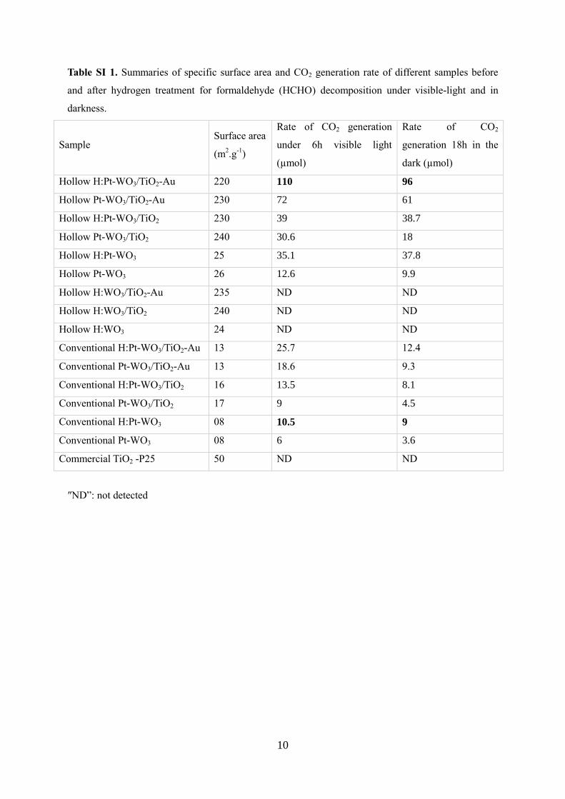
Table SI 1. Summaries of specific surface area and CO2 generation rate of different samples before
and after hydrogen treatment for formaldehyde (HCHO) decomposition under visible-light and in
darkness.
Sample Surface area
(m2.g
-1)
Rate of CO2 generation
under 6h visible light
(µmol)
Rate of CO2
generation 18h in the
dark (µmol)
Hollow H:Pt-WO3/TiO2-Au 220 110 96
Hollow Pt-WO3/TiO2-Au 230 72 61
Hollow H:Pt-WO3/TiO2 230 39 38.7
Hollow Pt-WO3/TiO2 240 30.6 18
Hollow H:Pt-WO3 25 35.1 37.8
Hollow Pt-WO3 26 12.6 9.9
Hollow H:WO3/TiO2-Au 235 ND ND
Hollow H:WO3/TiO2 240 ND ND
Hollow H:WO3 24 ND ND
Conventional H:Pt-WO3/TiO2-Au 13 25.7 12.4
Conventional Pt-WO3/TiO2-Au 13 18.6 9.3
Conventional H:Pt-WO3/TiO2 16 13.5 8.1
Conventional Pt-WO3/TiO2 17 9 4.5
Conventional H:Pt-WO3 08 10.5 9
Conventional Pt-WO3 08 6 3.6
Commercial TiO2 -P25 50 ND ND
″ND”: not detected

11
Figure SI 7. A) SEM images and XRD pattern (B) of the hollow H: Pt-WO3/TiO2-Au after the fifth
cycle.
Figure SI 8. Schematic of hollow H:Pt-WO3/TiO2-Au with strong sunlight absorption, high surface
area, and high concentration of oxygen vacancies.
2 theta (deg.)
20 30 40 50 60 70
Inte
ns
ity
(a
.u.)
A B
1 µm
WO3
TiO2
Au
VB
WO3 TiO2 WO3 TiO2
e-
Pt
Irradiation- Charging process In dark- Discharging process
h+ h+ h+ h+
h+ h+ h+ h+
Pt
Au Au
H2O
H+,O2
H+,O2
H2O2, OH
Visible light
VB
CB
CB
VB
CB
VB
CB
H+,O2
H2O2, OH ..HCHOCO2
HCHOCO2
e- e- e- e-
e- e- e-
e- e- e-
e- e- e- e-
e-e- e- e-
e- e- e- e-
e- e- e- e-