artillery - fort sillsill- · at division artillery, there is a target acquisition platoon in the...
TRANSCRIPT
ARTILLERY TRENDS
OCTOBER 1964
US ARMY ARTILLERY AND
MISSILE SCHOOL

Instructional Aid Number 31
COVER Increased target acquisition will
provide not only more lucrative and accurately located targets for the artillery's delivery means but also the key for first volley fire for effect. These increased capabilities will be derived from equipment, such as the VATLS, AN/MPQ-4A, or LASER, which are "chapters" in Will Adjust To "The" First Round Hit—The Future Story of Target Acquisition on page 5.
ARTICLES FDC van features—Design with Efficiency ................................. 2 Will Adjust To "The" First Round Hit—
The Future Story of Target Acquisition ............................... 5 Artillery Tool House ..................................................................... 41 NEW Cannon Potential ................................................................ 43 THE PAYQFF IS ACCURACY ................................................... 47
NEWSNOTES News of, for, about the Artillery World ........................................ 52 Readers' Comments ...................................................................... 56
RESIDENT COURSE SCHEDULE Resident Courses—U.S. Army Artillery and Missile School ....... 57
STATUS OF TRAINING LITERATURE AND FILMS TRAINING LITERATURE ......................................................... 62 TRAINING FILMS ...................................................................... 63
ARTILLERY TRENDS is a publication of the United States Army Artillery and Missile School appearing only when sufficient material of instructional nature can be gathered.
1

FDC van features . .
Design with Efficiency Captain Phillips G. P. Eliot
2d Howitzer Battalion, 31st Artillery
The physical arrangement of an FDC is vitally important, and, like Army mess trucks, battalion FDC vans are arranged in many different ways. One FDC van arrangement designed by the 2d Howitzer Battalion, 31st Artillery, promotes quietness and efficiency (fig 1). Constructed in a 2 1/2-ton M109 shop truck, the FDC arrangement is designed on the concept of no physical separation or space between the chart operators and computers. Such an arrangement of chart operators and computers allows implementation of a highly efficient system of checks within the FDC.
The S3 stands between the Battery A computer and the HCO and checks the actions of both. Next to the S3 is a writing table and a telephone which can be plugged into any circuit coming into or within the FDC, without disturbing the switchboard operator. This also places the S3 near the FM radios operating in the command/fire direction or fire direction radio nets (fig 2).
The chief computer stands between the Battery B and C computers and can thus check both battery computers and the VCO.
The assistant chief computer works at the writing board near the wall map. Without moving, he can monitor any telephone traffic, using one of the two phones stacked vertically on the wall (fig 2), and can operate the FM radios in the fire direction nets.
In addition to allowing an effective system of checks, this arrangement of charts and computers reduces the noise level and the amount of verbal traffic. In vans where the charts are against one wall and the computers are in line along another wall, chart data must be announced in a loud voice across the van, and all too often around an S3 or chief computer standing in the center of the van.
DESIGN FEATURES The physical arrangement of the equipment inside the FDC van, as
depicted in figure 1, provides several significant design features: ● Three FM radios (VRC-9), one AM receiver (GRR5), and the FDC
switchboard are mounted in the van. By grouping the communication equipment together, but separated from technical fire direction operations, the communications operators do not interfere with the technical FDC operations.
● The design provides space for visitors, umpires, and other non-operators within the FDC, but separates them from operational functions.
● Storage compartments and racks provide space for individual clothing and equipment.
2

Figure 1. Measurements and arrangement of equipment inside the M109 shop van.
3
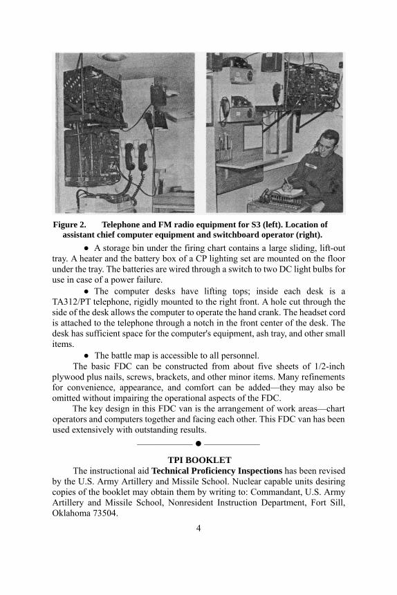
Figure 2. Telephone and FM radio equipment for S3 (left). Location of
assistant chief computer equipment and switchboard operator (right). ● A storage bin under the firing chart contains a large sliding, lift-out
tray. A heater and the battery box of a CP lighting set are mounted on the floor under the tray. The batteries are wired through a switch to two DC light bulbs for use in case of a power failure.
● The computer desks have lifting tops; inside each desk is a TA312/PT telephone, rigidly mounted to the right front. A hole cut through the side of the desk allows the computer to operate the hand crank. The headset cord is attached to the telephone through a notch in the front center of the desk. The desk has sufficient space for the computer's equipment, ash tray, and other small items.
● The battle map is accessible to all personnel. The basic FDC can be constructed from about five sheets of 1/2-inch
plywood plus nails, screws, brackets, and other minor items. Many refinements for convenience, appearance, and comfort can be added—they may also be omitted without impairing the operational aspects of the FDC.
The key design in this FDC van is the arrangement of work areas—chart operators and computers together and facing each other. This FDC van has been used extensively with outstanding results.
–––––––––––– ––––––––––––
TPI BOOKLET The instructional aid Technical Proficiency Inspections has been revised
by the U.S. Army Artillery and Missile School. Nuclear capable units desiring copies of the booklet may obtain them by writing to: Commandant, U.S. Army Artillery and Missile School, Nonresident Instruction Department, Fort Sill, Oklahoma 73504.
4
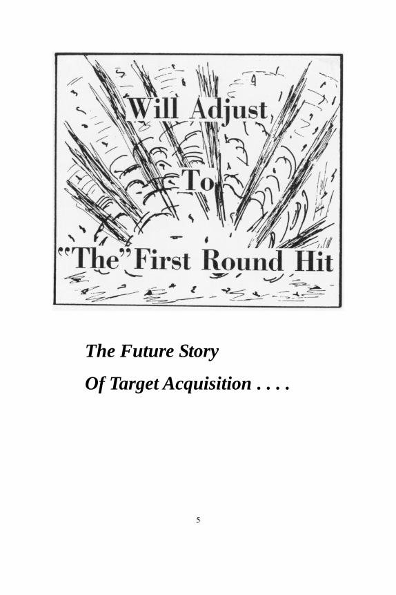
The Future Story
Of Target Acquisition . . . .
5

TARGET ACQUISITION ORGANIZATION
Lieutenant Colonel James E. Dick Target Acquisition Department
For many years the Artillery has depended on the forward observer to locate targets and on the time and ammunition consuming process of "will adjust" to place accurate fire on the enemy. Surveys were often conducted by a well placed (we hoped) pin in a map, and metro messages were likely to be obtained by a wet finger held in the air to guess at wind direction and speed. If we made a few miscalculations, we shot the errors out. On the battlefield of the future, we cannot afford this luxury, and we must use every means at our disposal to obtain accurate first volley fire for effect. These means include the elements normally associated with target acquisition: survey, ballistic meteorology and target location.
ELEMENTS AND MISSIONS Target acquisition elements are located at corps artillery, division artillery,
and in the artillery cannon, rocket, and missile battalions. The target acquisition means at corps artillery is the Field Artillery Target
Acquisition Battalion (FATAB) (fig 1) consisting of a headquarters and headquarters battery (fig 2) and three target acquisition batteries (fig 3). The missions of this battalion are to:
● Provide general target acquisition with the sound ranging, flash ranging, radar, and drone platoons.
● Conduct registration and adjustment of artillery weapons. ● Provide meteorological data for NATO ballistic messages, computer
messages, sound ranging messages, fallout messages and weather data to the Air Weather Service.
● Conduct and coordinate corps artillery survey operations. ● Perform comparative calibration of artillery weapons. ● Verify the location of nuclear bursts fired by friendly forces. ● Provide its component of the corps communication, observation, and
fire support coordination system. The tactical missions assigned to the FATAB are very similar to those of
any artillery unit. While the battalion is normally assigned a mission of general support of corps artillery, one or more of its target acquisition batteries may be given a mission of direct support or may be attached to a division artillery or an artillery group. To provide this versatility, each target acquisition battery has a processing section, which is a small operations platoon, and a liaison section.
6

At division artillery, there is a target acquisition platoon in the headquarters and headquarters battery (fig 4). The missions of this platoon are to:
● Provide general target acquisition by means of the surveillance radar section and the Visual Airborne Target Locator System (VATLS).
● Provide meteorological data for NATO ballistic messages, computer messages, fallout messages and weather data to the Air Weather Service. (Sound ranging messages will also be provided if required.)
● Conduct and coordinate division artillery survey operations. The direct support battalions have a target acquisition platoon in headquarters
and headquarters battery (fig 5) with the following missions: Provide general target acquisition using the countermortar radar and FO
sections. (There are nine other FO sections—three per firing battery.) Conduct registration and adjustment of artillery weapons. Conduct battalion survey operations.
A survey section(s) is also located in all general support cannon, rocket, and missile battalions.
Figure 1. FA Target Acquisition Battalion, Corps Artillery.
Figure 2. Headquarters and Headquarters Battery, FATAB, Corps
Artillery.
7

Figure 3. FA Target Acquisition Battery, FATAB, Corps Artillery.
Figure 4. Target Acquisition Platoon, Headquarters and Headquarters Battery, Division Artillery.
Figure 5. Target Acquisition Platoon, Headquarters and Headquarters Battery, direct support battalion.
This summary of artillery target acquisition organization has been brief, but it may help you fit together the articles that follow.
8
Genealogy Of Target Acquisition
Captain Joe F. Stewart Target Acquisition Department
For as long as he has been on earth, man-has depended on his "built in" target acquisition devices to furnish the location of his food and enemies. These devices are, of course, his eyes, ears, and sense of smell. We find that some of the creatures which inhabit the earth have "built in" target acquisition devices which man is trying to duplicate for his present day needs. For instance, the rattlesnake can detect a change in temperature as small as .001 degree centigrade. Though unable to detect this minute a change in temperature, the infrared systems of today do utilize a heat detection principle.
A frog's eyes are designed primarily to see two things—moving bug-sized objects within range of the frog's tongue and approaching large objects which might be an attacker. Many of the present day radars use a "moving target indicator" system in order for the operator to distinguish between the unwanted stationary targets and the desired moving targets.
The porpoise or dolphin emits high pitched squeaks, actually hears the return echoes, and determines even the type of fish which are in the area. The principle of SONAR is that of transmitting energy through the surrounding water and receiving the echoes in order to detect underwater objects. The study which applies the animal capabilities to present electronic technology is known as bionics.
TARGET ACQUISITION DEVELOPMENT The development of target acquisition began in 1608 when a scientist
from Holland invented the telescope. The principle of the telescope was later refined and is used today in many of our modern visual aids.
In 1916, a group of American, French, and British scientists determined that it was possible to locate artillery by the sound the weapons made when fired. American sound ranging and flash ranging (visual observation) units were activated and operated during World War I. In 1922, an observation battery was organized at Fort Bragg, North Carolina, to assist in the development of sound and flash techniques. By the end of World War II, 25 observation battalions had been activated, 24 of which saw combat.
The first experimental radar was developed in 1934 and since that time its uses have included the location of aircraft, artillery, and moving ground targets. Radar was first used to locate enemy weapons at the end of World War II.
In 1961, the Observation Battalion was renamed Field Artillery Target Acquisition Battalion (FATAB).
9

ORGANIZATION AND EQUIPMENT There are a total of three full strength field artillery target acquisition
battalions in addition to three other battalions at various reduced strengths in the Army. A battalion is normally assigned to a corps artillery.
Target acquisition equipment organic to the FATAB consists of one AN/MQM-57A Drone System in the headquarters battery and sound ranging, flash ranging, and counterbattery radar platoons in each of the three letter batteries. The drone's primary mission is to verify suspect target locations with the camera it carries. The flash platoon can provide locations of enemy weapons from telltale muzzle flashes or smoke and locations of any identifiable targets to limits of visibility. Both the sound ranging and counterbattery radar platoon have the primary mission of locating hostile artillery.
At division artillery level, there is a target acquisition platoon equipped with the AN/TPS-25A ground surveillance radar. The ground surveillance radar is designed to locate moving targets such as walking personnel or moving vehicles. The Visual Airborne Target Locator System (VATLS), when issued, will currently be an augmentation to the division artillery, headquarters battery. The VATLS is designed to aid the aerial observer in making accurate target locations.
The direct support battalions have a target acquisition platoon equipped with the AN/MPQ-4A countermortar radar. These radars can rapidly locate mortar firing positions after detecting the mortar projectiles in flight.
There are other combat surveillance devices authorized in the divisions and corps designed to detect hostile positions and activity, though they normally do not provide sufficient accuracy to permit obtaining precise locations of targets. All divisions have a similar number of these items except the airborne division which is not authorized the drone system. Among these combat surveillance devices are the side looking airborne radar (APS-94), the airborne infrared system (UAS-4), the combat surveillance drone (MQM-57A with other than artillery mission), the short range ground surveillance radar (PPS-4), and the medium range ground surveillance radar (TPS-33).
The side looking airborne radar (SLAR) is designed to provide combat surveillance in areas of enemy activity. They are particularly valuable at night and during inclement weather when photography and the quality of infrared imagery is greatly reduced. The SLAR is authorized for the aviation battalion of the division and for the armored cavalry regiment of the corps.
The airborne infrared system provides a passive, infrared, surveillance system which includes airborne data, display, and recording. It is authorized for the aviation battalion.
The combat surveillance drone is the same unmanned aerial platform that is in the artillery. However, its assigned mission is aerial photographic reconnaissance and surveillance. It is authorized to the aviation battalion (except airborne division) and to the armored cavalry regiment.
10

The short and medium range ground surveillance radars are designed to detect moving targets in the same manner as the long range ground surveillance radar found at division artillery. The effective range and accuracy of these radars is somewhat less and they are authorized for the infantry battalion, tank battalion, armored cavalry squadron, and mechanized infantry battalion of the division and the armored cavalry regiment of corps.
What of the future? It is quite apparent that target acquisition means must be able to locate targets to the extent of the weapons delivery range. With the advent of the current family of missiles, it is increasingly important that longer range target acquisition devices be available to the artillery commander. Presently, long range patrols, army aircraft, and the U.S. Air Force must provide locations of targets which are Further than 15 to 20 kilometers beyond FEBA.
There are some new items now in development which should serve to increase the present range capabilities of target acquisition. With today's technological achievements, it is possible that new ideas will make a break-through in new types of target locating devices.
INSTANT SURVEY Captain Lloyd W. Lathrop
Target Acquisition Department His air reconnaissance completed, the target acquisition platoon leader of
the direct support battalion dismounts from the LOH and runs toward the battalion radar set where his battalion commander is waiting for his report. "Colonel, the battalion will be able to mass its firepower in approximately 20 minutes!"
The likelihood of conflict in remote areas of the world results in an increased requirement upon the artillery to be able to shoot where no maps are available and survey is extremely difficult. The artillery must be able to deliver these fires quickly and accurately, often without survey or adequate time to complete the observed firing chart. The AN/MPQ-4A (fig 6) aids in accomplishing the requirement of shooting without survey or maps. This mobile, countermortar radar, located in the headquarters battery of each direct support battalion, has already proven its one-round capability as a mortar locator and its accuracy as an observer for high-burst and center-of-impact registrations. The combined characteristics of the AN/MPQ-4A aid in delivering timely and accurate fires, even when maps and survey are not available.
AN/MPQ-4A OPERATION
The crew emplaces the radar near the center of the battalion position. The radar location should meet the normal positioning require-
11
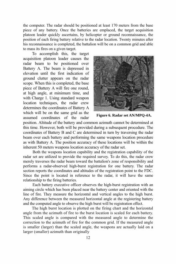
the computer. The radar should be positioned at least 170 meters from the base piece of any battery. Once the batteries are emplaced, the target acquisition platoon leader quickly ascertains, by helicopter or ground reconnaissance, the position of each firing battery relative to the radar location. Twenty minutes after his reconnaissance is completed, the battalion will be on a common grid and able to mass its fires on a given target.
Figure 6. Radar set AN/MPQ-4A.
To accomplish this, the target acquisition platoon leader causes the radar beam to be positioned over Battery A. The beam is depressed in elevation until the first indication of ground clutter appears on the radar scope. When this is completed, the base piece of Battery A will fire one round, at high angle, at minimum time, and with Charge 1. Using standard weapon location techniques, the radar crew determines the coordinates of Battery A which will be on the same grid as the assumed coordinates of the radar position. Altitude of the battery and common azimuth cannot be determined at this time. However, both will be provided during a subsequent procedure. The coordinates of Battery B and C are determined in turn by traversing the radar beam over each battery and performing the same weapons location procedure as with Battery A. The position accuracy of these locations will be within the inherent 50 meters weapons location accuracy of the radar set.
Both the weapons location capability and the registration capability of the radar set are utilized to provide the required survey. To do this, the radar crew merely traverses the radar beam toward the battalion's zone of responsibility and performs a radar-observed high-burst registration for one battery. The radar section reports the coordinates and altitudes of the registration point to the FDC. Since the point is located in reference to the radar, it will have the same relationship to the firing batteries.
Each battery executive officer observes the high-burst registration with an aiming circle which has been placed near the battery center and oriented with the line of fire. They measure the horizontal and vertical angles to the high burst. Any difference between the measured horizontal angle at the registering battery and the computed angle to observe the high burst will be registration effect.
The high burst location is plotted on the firing chart and the horizontal angle from the azimuth of fire to the burst location is scaled for each battery. This scaled angle is compared with the measured angle to determine the correction to the azimuth of fire for the common grid. If the measured angle is smaller (larger) than the scaled angle, the weapons are actually laid on a larger (smaller) azimuth than originally
12

selected. Normal gunnery procedures are used to correct this error and apply the registration corrections. The measured vertical angle will be converted to a vertical interval using the range scaled from the battery center to the high burst. This vertical interval, when applied to the altitude of the registration point, will provide each battery with altitude.
The survey and registration are complete; the elapsed time was under 20 minutes. Now, when the radar crew locates a mortar or a forward observer adjusts on a target, first round fire for effect will be delivered by the entire battalion.
DIVISION ARTILLERY USE The division artillery can also mass fires using the AN/MPQ-4A, for it
would be a simple task to exploit the 10,000-meter range capability of the AN/MPQ-4A and locate the flank batteries of the right and left direct support battalions. These battalions would merely slide the coordinates established by their own organic radar, thus placing the division artillery on a common grid.
The expansion of control need not be limited to the direct support battalions of the division artillery. Any unit emplaced within the 10,000-meter range capability of the base radar or flank battalion radars, may request use of the technique, thus causing their artillery to become part of the available massed fires.
The technique, equipment, and organizations require no extensive training requirement, just the expansion of various unit standard operating procedures to provide the necessary coordination to achieve instant survey. The techniques outlined in this article are the author's and do not reflect the position of the USAAMS at this time, but in the near future, these techniques will be tested for practicability and accuracy. Results will be published in a subsequent issue.
15B1 FOR MPQ-4A Mr. James F. O'Malley
Target Acquisition Department The 15B1 is a transportable training set designed for use with a modified
radar set AN/MPQ-4A for the efficient training of personnel in locating mortars. Designed for use in the classroom or in the field, the target simulator eliminates the need for vehicles, mortars, firing ranges, and ammunition in the training of radar personnel.
The 15B1 target simulator (fig 7) generates pulses that accurately duplicate actual projectile echoes on the radar scope. One to four targets can be presented on the radar scope at a range of 1,000 to 10,000 meters from the radar. Any trajectory that can be achieved by an actual projectile can be simulated by the 15B1, including the direction of fire, rate of fire, quadrant elevation, and the velocity and comparable size of ments for weapons location and radar gunnery applications. The assumed altitude and coordinates of the radar position are inserted into
13
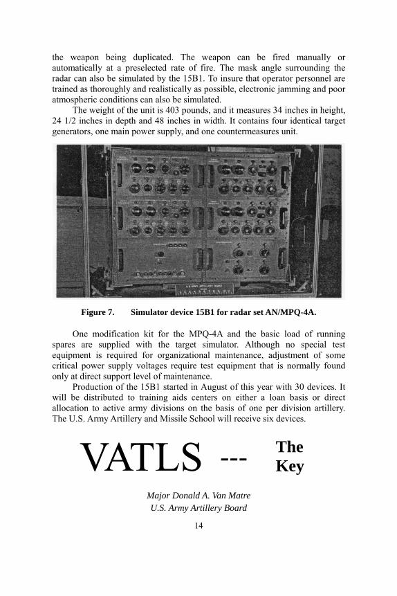
the weapon being duplicated. The weapon can be fired manually or automatically at a preselected rate of fire. The mask angle surrounding the radar can also be simulated by the 15B1. To insure that operator personnel are trained as thoroughly and realistically as possible, electronic jamming and poor atmospheric conditions can also be simulated.
The weight of the unit is 403 pounds, and it measures 34 inches in height, 24 1/2 inches in depth and 48 inches in width. It contains four identical target generators, one main power supply, and one countermeasures unit.
Figure 7. Simulator device 15B1 for radar set AN/MPQ-4A.
One modification kit for the MPQ-4A and the basic load of running spares are supplied with the target simulator. Although no special test equipment is required for organizational maintenance, adjustment of some critical power supply voltages require test equipment that is normally found only at direct support level of maintenance.
Production of the 15B1 started in August of this year with 30 devices. It will be distributed to training aids centers on either a loan basis or direct allocation to active army divisions on the basis of one per division artillery. The U.S. Army Artillery and Missile School will receive six devices.
VATLS --- The Key
Major Donald A. Van Matre U.S. Army Artillery Board
14
The burning desire in the heart of every field artilleryman is to provide the assurance of the "first round hit." The imminent key to this achievement is a target acquisition capability that can maintain the same pace as our modern weapons in use and in development.
Thus, VATLS, the Visual Airborne Target Locator System (fig 8), provides the artillery with greatly increased target acquisition capability. Though still undergoing tests, initial field tests by the U.S. Army Artillery Board show a potent and devastating effect which will result from the use of this sensory addition to the artillery aerial observer's equipment.
The observer, who controls the VATLS operation, locates targets by using either the unaided eye, binoculars, or the variable magnification telescope. Using the telescope, the target is centered in the concentric circle reticle and a "mark" is made. This mark, the depression of a contact button, communicates to the ground the aircraft attitude, telescope azimuth and depression to target, and target classification to the ground subsystem. The primary mode of operation is a "two-sight" technique providing an aerial base from which the target location is fixed. This technique is similar to target area survey. On each end of the base, the ground tracking radar and distance measuring equipment fix the aircraft location. The fixed output of the system are the UTM coordinates and the altitude of the target computed in the integral digital computer.
The accuracies achieved today with VATLS were unthinkable to aerial observers during World War II or the Korean conflict. The aircraft-target range is primarily related to the visual acuity of the aerial observer coupled with the target size and contrast of surrounding terrain. The present day role of the artillery aerial observer will remain the same with the addition of this highly effective system for the accomplishment of his mission.
The ultimate design of VATLS will provide an airborne system for mounting in a light observation helicopter (LOH). The multiple advantages of maneuverability and decreased exposure time make a helicopter preferable to a fixed-wing aircraft.
The initial orientation of VATLS is accomplished by "run-up" of the precise airborne gyro and emplacing the ground tracker with survey and directional control. However, if survey control is unavailable, the ground station will be located and direction given by the airborne equipment. Position and direction control can be based on real or assumed data. This permits a unique internal survey in a fraction of the time presently needed within a battalion or division artillery in unmapped areas. A devastating TOT will be the result.
Though the "two-sight" technique using an aerial base is the primary operational mode, the incorporation of a LASER (Light Amplification by Stimulated Emission of Radiation) for aircraft-to-target distance measurement in the next generation of VATLS will provide a "one-sight" mode. Advantages of VATLS include occupying less time in a vulnerable position on the battlefield and requiring the aerial observer to locate a particular target only once on the ground.
15

The target coordinates from VATLS are used in conjunction with the outputs of the gyro azimuth orientor and chronograph for muzzle velocity measurement and up-to-date meteorological and survey information; thus, the key for "first round hit" is at hand. These data, integrated and applied within the Gun Direction Computer, M18, to the cannon trajectories, open the door to "first round hit" accuracy. Bonus effects accrue with the advantages of reduced ammunition expenditure and expediency of "predicted fire" techniques.
Figure 8. Ground station control equipment including shelter-mounted
computer, tracker, distance measurement equipment, and power generator. Airborne station mounted in co-pilot's door of UH-1B.
The Visual Airborne Target Locator System is a giant step forward in target acquisition for the Army. Potential value can only be realized after the equipment is employed with tactical units. The benefits will be great—and the "first round hit" a reality.
Astronomic Azimuth
Determinations Captain D. M. Whipp
U.S. Coast and Geodetic Survey Astronomic observation is a valuable method of obtaining a quick,
reliable azimuth of artillery accuracy, if the weather permits its use. But, because it is considered too difficult to use, the M2 aiming circle containing a magnetic needle is employed by artillery units for initial laying even though the accuracy required for an artillery azimuth can seldom be achieved using the aiming circle.
16

A examination of the rule-of-thumb restriction placed on the astronomic azimuth determination system reveals many areas which can be modified without an adverse effect on accuracy. Since the restrictions are self-imposed, they can be easily changed to speed up considerably the determination of an azimuth. The following changes concerning astronomic observation have been approved and will appear in the next edition of FM 6-2, Artillery Survey:
● Reduce the permitted minimum altitude angle from 350 to 0 mils. ● Retain the maximum altitude angle at 800 mils, but allow an increase to
1,000 mils with special considerations. ● For the altitude method use the rate of change curve instead of the rule
limiting observations to bodies within 30 degrees north and south of the prime vertical.
● For the hour-angle method, allow the observation of any celestial body that can be seen, except when its altitude exceeds the maximum altitude angle of 800 to 1,000 mils. These changes would permit astronomic observations for azimuth determination at nearly any hour of the day or night and in any latitude (weather permitting). In latitudes above 70 degrees, and in some other cases explained later, the hour angle method must be used.
In astronomic observations, horizontal refraction will seldom exceed 0.02 mil; therefore, no attempt need be made to correct for this. In order to reduce the effect of horizontal refraction, stations should be selected so that lines of sight which cross the boundary between areas of different temperature will be normal to the boundary. Areas of different temperature include geography such as sun-baked plowed fields or sand, which would be hotter than water or pasture.
REDUCING THE MINIMUM ALTITUDE ANGLE In the past, restricting the minimum altitude angle was taken from rather
stringent requirements imposed upon higher order survey. Such a restriction is not necessary for artillery survey accuracy. At low altitudes there is a large vertical refraction correction which must be applied to correct the observed vertical angle to true altitude. Although this refraction correction, obtained from the Army Ephemeris, TM 6-300, is large, the probable error (PE) of the refraction correction is small by artillery standards. In general, the PE of the vertical refraction correction is approximately equal to the correction divided by 300. The PE increases rapidly for angles below 10 mils; for example, a vertical angle of 8 mils has a PE of the refraction correction of about 0.148 mils.
If the star that is being observed is moving vertically, this would introduce little or no error into the computed azimuth. If the star is moving at the same rate in azimuth as it is in altitude, the PE in the vertical refraction would affect the azimuth in like degree. When working in low altitudes, some stars, when setting, move almost vertically. A low altitude angle may be used for observing such stars. When near the horizon, stars near the prime vertical are ideal.
MAXIMUM ALTITUDE ANGLE The restriction on the maximum altitude angle is based on the error
17

introduced into the horizontal angle measurement. The error in the horizontal angle measurement is equal to the tangent of the altitude of the star multiplied by the error in leveling the plate of the instrument. When using a T2 or T16 theodolite, one division of the plate bubble is equal to 0.1 mil. If the plate is not level by one division and the altitude angle is 800 mils, the horizontal angle measurement will be in error by 0.1 mil. If the altitude angle is 1,000 mils, the error in the horizontal angle measurement will be 0.2 mil. For this reason, the maximum altitude angle restriction must be retained, with special precautions for leveling the instrument between 800 mils and 1,000 mils.
ALTITUDE METHOD The true test of whether a star is suitable for use in astronomic azimuth
determination by the altitude method is to compute the rate of change of azimuth against altitude, or simply, how many mils of error in azimuth are created by 1 mil of error in altitude. Such a formula can be written in many forms, but one of the most useful is—
Change in azimuth Tan Lat-Tan Alt Cos Az Change in altitude
= Sin Az
The ratio Change in azimuth will be referred to as "rate" throughout Change in altitudethe remainder of this article.
To simplify field use of this formula, the curves corresponding to a rate of 0.0., 0.5, 1.0, and 3.0 have been computed and drawn on each of the star identifier templates used by most field units. Plates to scale will appear in the new survey manual. Examples of the plates for latitude 35 degrees and 45 degrees are depicted in figure 9. To use the plates in the new manual, place the template corresponding to the latitude over the plate in the manual and sketch the curve for the working "rate" on the template. A sharp grease pencil will give a clear curve. The areas between the curves are labeled as follows:
A. Stars in this area have a "rate" between 0.0 and 0.5. They are the best stars for use in astronomic observation and should be chosen except when the altitude is too high.
B. Stars in this area have a "rate" between 0.5 and 1.0. Fourth order azimuth can be obtained from these stars with reasonable care.
C. Stars in this area have a "rate" between 1.0 and 3.0. Fifth order azimuth can be obtained from these stars with reasonable care.
D. Stars in this area have very large "rates." If necessary to use a star appearing in this area, they must be computed by the hour-angle method.
It is suggested that only the curves containing the area of immediate interest be traced on the template since the full set of curves
18
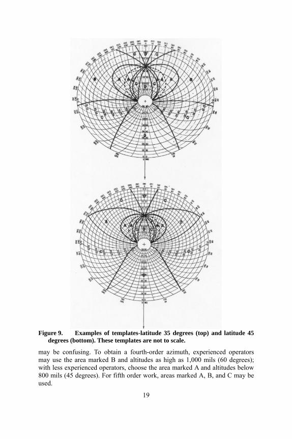
Figure 9. Examples of templates-latitude 35 degrees (top) and latitude 45
degrees (bottom). These templates are not to scale.
may be confusing. To obtain a fourth-order azimuth, experienced operators may use the area marked B and altitudes as high as 1,000 mils (60 degrees); with less experienced operators, choose the area marked A and altitudes below 800 mils (45 degrees). For fifth order work, areas marked A, B, and C may be used.
19

An examination of figure 9 indicates that the best stars lie to the north in the northern hemisphere—that is, the azimuth is less than 1,600 mils or more than 4,800 mils. When north of latitude 40 degrees, stars to the south of the prime vertical should not be used for a fourth order or higher azimuth. The ideal stars, those which are moving vertically and have a "rate" of zero, lie along a curved line (shown dotted in figure 9) connecting the zenith of the north pole and the observer's zenith. The altitude of the zenith of the north pole is equal to the observer's latitude. Those stars which are on that part of the curve near the observer's zenith cannot be used because of the restriction on the maximum altitude angle.
The higher the "rate" of the star chosen, the more accurate the vertical angle must be to obtain the required accuracy. It has been arbitrarily decided that to obtain a fourth-order azimuth only stars with a "rate" of 1.0 or less may be used. To obtain a fifth-order azimuth, stars with a "rate" as high as 3.0 may be used. To determine an azimuth of fourth-order accuracy, if a star with a "rate" of 1.0 has been chosen, the combination of all probable errors must not exceed 0.1 mil. This will require that the probable error (PE) of the vertical angle should not exceed 0.05 mil. However, if the star chosen has a "rate" of only 0.1 the PE of the vertical angle measurement could be as high at 0.5 mil. Therefore, it is better to choose stars with small "rates".
HOUR ANGLE METHOD
For Army artillery use, any star that can be seen may be used for computation by the hour-angle method if the altitude angle does not exceed the maximum allowed. The true test of whether a star may be observed for computation by the hour-angle method is to examine the rate of change of azimuth against time. It can be shown that this rate of change of azimuth against time, in the worst case, will not exceed 0.25 mils per second. Thus, if time is carefully controlled to the nearest second an azimuth of artillery accuracy may be obtained. Much better results will be obtained if the star chosen is moving slower in azimuth. A star that is in good position for computation by the altitude method is also in good position for computation by the hour-angle method. If a star is slightly out of position for computation by the altitude method, that method may fail completely, but the hour-angle method will always give a reasonable result. The quickest computation will result if a star is chosen that is suitable for computation by the altitude method and both the altitude and time are observed. The azimuth may then be computed by the time altitude method. The best star or position of the sun should be chosen anytime the tactical situation will permit waiting for it.
By these modifications and improvements to astronomic observation requirements, we have increased the value of one of the artillery's handiest tools.
20
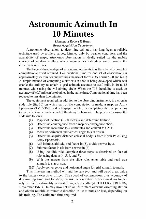
Astronomic Azimuth In 10 Minutes
Lieutenant Robert P. Braun Target Acquisition Department
Astronomic observation, to determine azimuth, has long been a reliable technique used by artillery survey. Limited only by weather conditions and the availability of maps, astronomic observation is ideally suited for the mobile concept of modern artillery which requires accurate direction to insure the effectiveness of fires.
The biggest disadvantage of astronomic observation is the relatively complex computational effort required. Computational time for one set of observations is approximately 45 minutes and requires the use of forms (DA Forms 6-20 and 6-11). A simple method of computing a star or sun shot is being developed which will enable the artillery to obtain a grid azimuth accurate to ±2.0 mils, in 10 to 15 minutes while using the M2 aiming circle. When the T16 theodolite is used, an accuracy of ±0.7 mil can be obtained in the same time. Computational time has been reduced to less than five minutes.
The equipment required, in addition to the observing instrument, is a circular slide rule (fig 10) on which part of the computation is made, a map, an Army Ephemeris (TM 6-300), and a 10-page booklet for completing the computations (which also can be made a part of the Army Ephemeris). The process for using the slide rule follows:
(1) Map spot location (±300 meters) and determine latitude. (2) Determine convergence from a map or convergence chart. (3) Determine local time to ±30 minutes and convert to GMT. (4) Measure horizontal and vertical angle to sun or star. (5) Determine angular distance celestial body is from North Pole using
Army Ephemeris. (6) Add latitude, altitude, and factor in (5), divide answer by 2. (7) Subtract factor in (5) from answer in (6). (8) Using the slide rule, complete three steps as described on face of
rule, using data in (4, 5, 6, and 7). (9) With the answer from the slide rule, enter table and read true
azimuth to star or sun. (10) Apply convergence and horizontal angle for grid azimuth to mark.
This time-saving method will aid the surveyor and will be of great value to the battery executive officer. The speed of computation, plus accuracy of determining time and location, means the executive officer must no longer rely on the questionably accurate magnetic needle (ARTILLERY TRENDS, November 1963). He may now set up an instrument over his orienting station and obtain reliable astronomic direction in 10 minutes or less, depending on his training. The estimated time required
21
Figure 10. Prototype model of the astronomic slide rule.
to train the average student officer to obtain an astronomic azimuth in this manner would be from 12 to 15 hours.
The surveyor, in addition to saving about 45 minutes of computational time, has a rapid method of checking computations on DA Form 6-11, and he can check the azimuth he is carrying with little loss of time.
What's New In The DRONE SYSTEM
Captain Gary L. Nilson Target Acquisition Department
The AN/USD-1 Surveillance Drone has been redesignated the AN/MQM-57A. The change in nomenclature is derived from AR 705-36 which states that all drone and missile systems are being renamed to establish
22

a uniform terminology system among the armed services. In the near future, the drone system will receive a new command system
(fig 11) for controlling the drone aircraft (fig 12). The new control system is highly resistant to jamming. The ground station portion of this system utilizes two types of antennas and has two power output selections. Using an omni-directional antenna (the inverted E-shaped device on top of the mast section in figure 11), the power output may be either 75 watts or 12.5 kilowatts. The low power output selection will be used while the drone is being checked on the launcher prior to flight and for flights in the immediate area of the ground station. The high power output selection will be used to control the drone at greater distances, approximately 30 kilometers.
To restrict the transmitted signal to a smaller area and to obtain the maximum range of the system of approximately 60 kilometers, the ground station will switch to a high gain directional antenna unit (the two large parallel antennas in figure 11). This directional antenna unit, with the high power transmitter output (12.5 kilowatts), will transmit an effective radiated signal of approximately 400 kilowatts.
The transmitted signal, using either antenna, is only transmitted for a maximum of a few hundred micro-seconds. However, a complete signal is transmitted every time the drone is given a new command, with a portion of this signal repeated every three seconds. This repeated portion of the signal acts as a range safety device for flying in limited range areas. If the drone does not receive a signal for 10 seconds, it will automatically deploy the recovery parachute. Under combat conditions, the signal repetition for range safety could be eliminated, and the transmitter would only put out a signal when the drone is given a new command. Under this condition the parachute would not automatically deploy after 10 seconds. Because the signal would be transmitted sporadically, it would be difficult to detect by an enemy. This is one of the means of making the drone a secure system. If the signal was detected, it is felt that it would be difficult to jam because of the high power output of the transmitter.
To further secure this command system, a coded address is transmitted preceding every command that is sent to the drone. The receiver in the drone must accept this coded address before the drone will execute the command. Besides making the command system more secure, it also provides a means of controlling more than one drone on the same frequency. This is accomplished by using a different coded address for each drone. The new control system consists of:
● All new control boxes, transmitters, address coders and antennas for the ground stations. (Two ground stations are authorized in each drone system). The transmitted coded address can be changed through the use of selector knobs on the coder box.
● New receivers, address decoders and antennas for each drone aircraft (12 drones are authorized in each drone system). The address decoder uses various printed circuit boards to correspond with the transmitted coded address.
23

● A few new pieces of test equipment for testing and checking the drones and ground stations.
● Modifications to each drone aircraft to accommodate the new receivers, decoders, and antennas and to a few pieces of test equipment presently authorized.
AN/MPQ-29 and AN/DPN-62V
Figure 11. New Command system.
The AN/MPQ-29 tracking and plotting radar (fig 12), used for tracking the drone and manned aircraft, is slated for some modifications. Even though the radar was originally intended to track aircraft out to a distance of 92 kilometers, the maximum effective tracking range that has been attained is approximately 30 kilometers. This range was obtained by using a beacon transponder. The modifications to be made to this radar will greatly increase the effective tracking range, provide greater reliability, and improve the low altitude tracking capability.
The AN/DPN-62V beacon transponder, used in conjunction with the tracking and plotting radar, is presently undergoing modification. This beacon transponder is carried on board the drone aircraft and is used to aid the radar in tracking the drone at great ranges. The modification will increase the dependability of the beacon transponder and aid the radar in low altitude tracking.
The new command control system, the modified AN/MPQ-29 tracking and plotting radar, and the modified AN/DPN-62V beacon transponder will be issued simultaneously. These items have been installed
Figure 12. Surveillance drone (left).
AN/MPQ-29 tracking and plotting radar (right)
24

on the equipment at the Combat Surveillance School, Fort Huachuca, Arizona, the drone unit in the 5th Mechanized Division, Fort Carson, Colorado, and are presently being installed in the drone units in Europe.
These modifications will make the drone a reliable and valuable means of target acquisition for the artillery and for battlefield surveillance for other units. They will enable the artillery commander to see deep into enemy territory without risk to human life.
Meteorological Sounding Balloons
CWO Robert G. Kelsey and CWO James A. Dunn Target Acquisition Department
Artillery meteorological sections are capable of sounding the atmosphere approximately every two hours. A limiting factor in the completion of a sounding, which is the time required for a sounding balloon to reach a required height, will be eliminated when the new meteorological system is developed and the sounding vehicle becomes a rocket or indirect methods of sounding the atmosphere are developed. Until the new system is developed, balloons will remain the primary method for carrying sensing elements into the atmosphere.
Currently there are two types of sounding balloons used by the artillery meteorological sections, the high altitude balloon ML-537/UM, and the fast rising balloon ML-541/UM.
The high altitude ballon ML-537/UM will carry a radisonde to altitudes in excess of 30,000 meters* before bursting. The rate of ascent of this balloon is approximately 330 meters per minute. Normally, this balloon is used for determining fallout, but it should be kept in mind that the data obtained from the sounding can be used to develop all types of messages. The ML-537/UM is used for both day and night observations.
The fast rising balloon ML-541/UM is designed to carry a radiosonde to altitudes of 23,000 meters*. The balloon is streamlined to permit a rate of ascent of about 500 meters per minute. Although this balloon is primarily used for daytime observations, it may be employed at night. However, its bursting altitude is reduced when used at night.
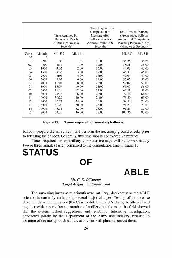
Times required for each type of sounding balloon to reach the top of a NATO zone are illustrated in figure 13, which also depicts the time needed for completion of the NATO message once the balloon has reached the top of a zone.
Total time in figure 13 is the time required to inflate the sounding
*NOTE: For quality control 80 per cent of the balloons furnished by the manufacturers must be able to attain these altitudes.
25
Time Required For Balloon To Reach
Altitude (Minutes & Seconds)
Time Required For Computation of Message After
Balloon Reaches Altitude (Minutes &
Seconds)
Total Time to Delivery (Preparation, Balloon
Ascent, and Computation Planning Purposes Only.)
(Minutes & Seconds)
Zone Altitude ML-537 ML-541 ML-537 ML-54100 0 - - - - - 01 200 :36 :24 10:00 35:36 35:24 02 500 1:31 1:00 12:00 38:31 38:00 03 1000 3:02 2:00 16:00 44:02 43:00 04 1500 4:33 3:00 17:00 46:33 45:00 05 2000 6:04 4:00 18:00 49:04 47:00 06 3000 9:05 6:00 19:00 53:05 50:00 07 4000 12:07 8:00 20:00 57:07 53:00 08 5000 15:09 10:00 21:00 61:09 56:00 09 6000 18:11 12:00 22:00 65:11 59:00 10 8000 24:16 16:00 23:00 72:16 64:00 11 10000 30:20 20:00 24:00 79:20 69:00 12 12000 36:24 24:00 25:00 86:24 74:00 13 14000 42:28 28:00 24:00 91:28 77:00 14 16000 48:32 32:00 23:00 96:23 80:00 15 18000 54:36 36:00 22:00 101:36 83:00
Figure 13. Times required for sounding balloons.
balloon, prepare the instrument, and perform the necessary ground checks prior to releasing the balloon. Generally, this time should not exceed 25 minutes.
Times required for an artillery computer message will be approximately two or three minutes faster, compared to the computation time in figure 13.
STATUS OF
ABLE Mr. C. E. O'Connor
Target Acquisition Department
The surveying instrument, azimuth gyro, artillery, also known as the ABLE orientor, is currently undergoing several major changes. Testing of this precise direction determining device (the C2A model) by the U.S. Army Artillery Board together with reports from a number of artillery battalions in the field showed that the system lacked ruggedness and reliability. Intenstive investigation, conducted jointly by the Department of the Army and industry, resulted in isolation of the most probable sources of error with plans to correct them.
26

SUMMARY OF MAJOR DEVELOPMENTS
The primary difficulty encountered by users of the orientor was the lack of assurance of the quality of results of an azimuth determination. Operating under controlled conditions and with a known azimuth for comparison, the system generally produced highly satisfactory results. However, it was noted that after the instrument had been subjected to field conditions, such as transport in tactical vehicles across country, the azimuth error frequently exceeded tolerable limits. The error was detected, only when an established azimuth was available for use as a comparison. Obviously, an azimuth determining device would be of no value if another azimuth had to be available to check each determination. Tests of the system showed that errors of this nature were caused by shock during transport which resulted in misalinement between the theodolite scales and the axis of the gyroscope. This potential error has been eliminated by the development of a new carrying case. The new case secures the sensing element in a shock mount, "birdcage" type suspension. The theodolite is still transported in the same carrying case but separated from the sensing element by a collartype arrangement. Tests of the system's ability to withstand shock in the new carrying case show that the errors caused by misalinement have been reduced to a negligible amount.
The test program revealed other areas where improvements were required. Under high heat conditions the L-shaped gyro bracket bent slightly, thus introducing an azimuth error. This condition has been corrected by prestressing the gyro bracket. Many less significant sources of error were detected and have been corrected as a result of these tests. A program to modify the orientors has been established whereby the manufacturer accomplishes needed work on all systems still at the plant (model C2B) and the Army performs the work on systems presently in depots or units.
All work on the model C2B has been completed by the manufacturer and the orientors turned over to the Army for issue.
The C2B model orientor is the same as the C2A. The B designation identifies the device as one produced under the second of two contracts.
The Army's part in the program to modify the orientor is being conducted at Granite City, Illinois. Instructions concerning the turn-in and replacement of C2A systems, now in the field, will be announced in the near future by the U.S. Army Mobility Command.
Commanders of units equipped with the surveying instrument, azimuth gyro, artillery, are encouraged to continue operator training of the instrument. Until the C2A models have been modified, continued care should be exercised in evaluating results of azimuth determinations. Units with C2B models or modified C2A models can expect system performance which meets required accuracy and reliability.
27

EFFECTIVE TARGET ACQUISITION COVERAGE
Major (Ret) Maxwell R. Conerly Target Acquisition Department
In order to accomplish its mission of supporting the ground gaining arms, the artillery must be able to move, shoot and communicate. If "fire for effect" rounds are to achieve the desired results, the artillery must be able to accurately locate the target. The fleeting nature of some tactical targets, the need for the first round kill concentrations, and the effective utilization of present fire direction computers makes rapid, accurate target location mandatory.
Artillerymen pride themselves in their ability to shoot. As a result, a great deal of research has gone into the development of weapons with greater range, increased accuracy, and mobility and more destructive ammunition.
The increased ability to deliver more effective fire emphasizes the importance of target location and the need for constantly improving present target acquisition equipment and techniques.
The Field Artillery Target Acquisition Battalion (FATAB) is the primary agency responsible for target acquisition at corps artillery level. During World War II, this unit was responsible for providing target acquisition coverage over a corps front of approximately 30 kilometers. Three letter batteries, as organized at that time, could provide sound and flash ranging coverage over this front.
The width of the corps front today is approximately three times that of World War II, and yet, in spite of the addition of the AN/MPQ-10 radars and the AN/MQM-57A Drone, the ability of FATAB to cover a wider front has improved very little. Using present equipment, the apparent solution to the problem appears to be the addition of another FATAB to each corps artillery, or at least an increase in the number of target acquisition batteries in each FATAB. Since there is a limitation in the number of available personnel, another solution has been found which is based on the successful completion of current developmental programs.
SOLUTION FOR MORE COVERAGE Sound ranging platoons using the sound ranging set currently under
development by the Canadian government (or a similar one) could reorganize, with no increase in the battalion strength, into three sections. Each section would be able to cover a 10,000-meter front or the same area currently covered by the entire platoon. This would provide adequate sound ranging coverage by the FATAB over a corps front of approximately 90 kilometers. Use of the radio link group AN/TRA-26
28

would usually eliminate the need for wire between the microphone position and the recorder. This would allow a reduction in the number of wiremen required in the reorganization.
In the present concept of flash long-base operations, observers from at least three observation posts must determine azimuths to a target. This confines the distance between adjacent OP's to 2,500 meters or less, and, in turn restricts the width of the area of coverage by the platoon. If equipped with the LASER, the platoon could be reorganized into six or more OP teams and placed under the command of the sound platoon leader. Polar coordinates of targets from these OP's would be sent to the sound central to be processed in the computer of the sound ranging set. Since each observer could provide polar coordinates of targets, OP's could be installed approximately 5 kilometers apart. This would provide adequate flash ranging coverage by the battalion over a corps front of approximately 90 kilometers.
Replacement of the AN/MPQ-10A radar with the long range AN/MPQ-32 or a similar type radar would provide adequate counterbattery radar coverage by the battalion over a corps front of approximately 90 kilometers.
Replacement of the AN/MQM-57A drone with the longer range AN/MQM-58A, which carries either of three types of sensors (camera, infrared, or SLAR), would provide adequate drone coverage over a corps front of approximately 90 kilometers.
Placing all of the devices in one letter battery on a common grid could be accomplished, using the Long Range Survey System, in approximately two hours. Presently the time required is about eight hours. This speed of employment would permit the target acquisition batteries to provide effective target acquisition coverage during fluid situations. With these concepts the FATAB could provide effective target acquisition coverage over the entire corps front to a distance of approximately 20 kilometers (or greater) beyond the forward edge of the battle area with no increase in personnel. Most of the enemy artillery would probably be employed in this area.
Under present concepts of employment of artillery, FATAB is assigned to corps artillery because division artillery does not have the organic fire power necessary to deliver the required counterbattery fires (by type and amount) in addition to providing close and continuous support to the maneuver elements. Since the corps artillery delivers the bulk of the fires on enemy cannon, rockets, and missiles, the location of enemy artillery should be reported to the corps artillery counterbattery intelligence officer. It would be a simple matter to arrange for any of the target acquisition agencies to establish a "quick-fire" communication channel with an artillery battalion FDC in the event immediate fire on targets located by that element is needed.
We have the necessary firepower to neutralize the enemy in a relatively short period of time, provided the location of all targets is known. Therefore, adequate target acquisition is the key to victory.
29

YOU DON'T NEED A CRYSTAL BALL
Mr. James O'Malley Target Acquisition Department
Although harassing and interdiction (H and I) fire planning is based on the study of maps, terrain, road nets available to the enemy, and all other target intelligence available, it still remains 100 percent guesswork! Why not take the guesswork out of H and I fire planning? You don't need a crystal ball when something better is provided—the ground surveillance radar AN/TPS-25A.
The AN/TPS-25A (fig 14) was issued to field units in 1959. It is designed to detect the presence of moving ground targets and to supply information on their location. The radar set takes over where binoculars and listening posts cannot see or hear. This offers the commander a valuable source of battlefield information at night and during other periods of limited visibility which may be unobtainable with any other means.
The TPS-25A is capable of detecting moving targets between 450 and 18,280 meters. The following list includes some of the moving targets that could be found in the battle area, and the ranges at which they can be detected with the radar set.
Target Average Range in Meters Crawling man .................................. 5250 meters Walking man .................................... 12000 meters Squad digging .................................. 10000 meters Squad walking ................................. 18000 meters Vehicles, boats, helicopters .............. 18280 meters
TECHNICAL AND TACTICAL REQUIREMENT The TPS-25A, like all other radar equipment, must have line-of-sight to a
target to make a detection. Therefore, the radar antenna must be emplaced on dominant terrain to "see" into the battle area, usually on the forward slope, toward the FEBA. This affords the radar more advantageous coverage of the area under surveillance, and offers background cover as a means of camouflage for the antenna. A well placed radar set can monitor exposed road networks, bridges, routes of approach and other open areas within range.
The tactical situation will govern the general location of the TPS-25A radar and its area of surveillance. Generally, what is valid for a firing battery is also applicable in selecting a TPS-25A position. These include accessibility of the position, communication requirements, concealment and cover, survey, security, logistic support and routes of approach to the location.
30
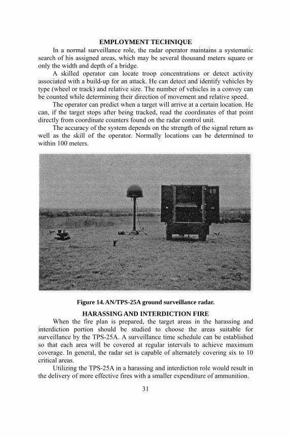
EMPLOYMENT TECHNIQUE In a normal surveillance role, the radar operator maintains a systematic
search of his assigned areas, which may be several thousand meters square or only the width and depth of a bridge.
A skilled operator can locate troop concentrations or detect activity associated with a build-up for an attack. He can detect and identify vehicles by type (wheel or track) and relative size. The number of vehicles in a convoy can be counted while determining their direction of movement and relative speed.
The operator can predict when a target will arrive at a certain location. He can, if the target stops after being tracked, read the coordinates of that point directly from coordinate counters found on the radar control unit.
The accuracy of the system depends on the strength of the signal return as well as the skill of the operator. Normally locations can be determined to within 100 meters.
Figure 14. AN/TPS-25A ground surveillance radar.
HARASSING AND INTERDICTION FIRE When the fire plan is prepared, the target areas in the harassing and
interdiction portion should be studied to choose the areas suitable for surveillance by the TPS-25A. A surveillance time schedule can be established so that each area will be covered at regular intervals to achieve maximum coverage. In general, the radar set is capable of alternately covering six to 10 critical areas.
Utilizing the TPS-25A in a harassing and interdiction role would result in the delivery of more effective fires with a smaller expenditure of ammunition.
31

DISTANCE MEASURING
EQUIPMENT CWO Ward B. Clifton Target
Acquisition Department While other branches of technology have discovered methods of
determining various quantities by indirect measurement, surveying, until recently, has relied on measuring distances with a steel tape. Many hours are required for such measurements, particularly on long lines, and as the Army increasingly narrowed its time limitations, surveying had to keep pace with some device capable of rapidly and indirectly obtaining required distances. Thus, the tellurometer solved this problem when it was introduced in 1958.
TELLUROMETER Extremely accurate, the tellurometer requires only 30 minutes for the
determination of any distance between 152 and 64,000 meters. This means that regardless of the time previously required to tape a distance—be it one or 100 hours—the job can be reduced to a half hour.
The tellurometer system consists of a master unit placed at one end of a line to be measured and a remote unit placed at the other end. The master transmits a modulated 10 centimeter radio carrier wave which is received by the remote unit and retransmitted to the master. Here the phase shift between transmitted and returned signals is displayed as a break in a circular trace on the graduated face of a cathode ray tube (CRT). The break in the trace indicates where the transit time for a partial wavelength is to be read on the CRT. By using different modulated frequencies, larger and larger partial wavelengths provide the total distance.
A definite limitation of the tellurometer is that ambigious readings can occasionally be obtained so that two computational solutions are possible. An experienced operator can quickly detect such a condition and obtain proper readings, but for the inexperienced, an error generally results.
The close spacing of graduations on the CRT and inherently poor observing conditions enhance possible errors in reading; the adjustment of controls required to obtain a break in the circular trace can be tricky for new operators; and the measurements can be made only from master to remote. This sometimes requires special considerations in employment and restricts versatility.
DME The disadvantages of the tellurometer have been eliminated in a new
device known as a Surveying Instrument, Distance Measuring, Electronic,
32
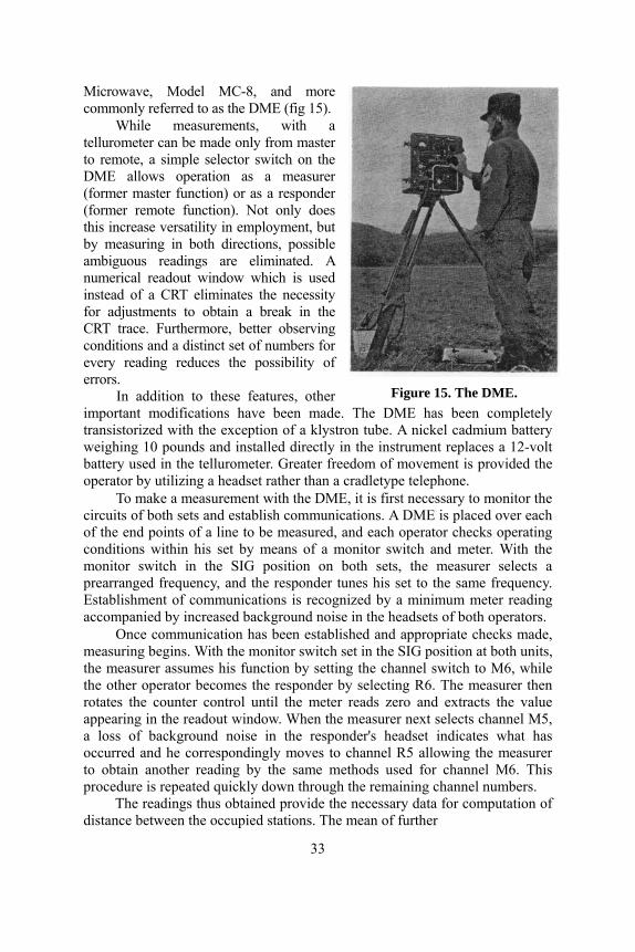
Figure 15. The DME.
Microwave, Model MC-8, and more commonly referred to as the DME (fig 15).
While measurements, with a tellurometer can be made only from master to remote, a simple selector switch on the DME allows operation as a measurer (former master function) or as a responder (former remote function). Not only does this increase versatility in employment, but by measuring in both directions, possible ambiguous readings are eliminated. A numerical readout window which is used instead of a CRT eliminates the necessity for adjustments to obtain a break in the CRT trace. Furthermore, better observing conditions and a distinct set of numbers for every reading reduces the possibility of errors.
In addition to these features, other important modifications have been made. The DME has been completely transistorized with the exception of a klystron tube. A nickel cadmium battery weighing 10 pounds and installed directly in the instrument replaces a 12-volt battery used in the tellurometer. Greater freedom of movement is provided the operator by utilizing a headset rather than a cradletype telephone.
To make a measurement with the DME, it is first necessary to monitor the circuits of both sets and establish communications. A DME is placed over each of the end points of a line to be measured, and each operator checks operating conditions within his set by means of a monitor switch and meter. With the monitor switch in the SIG position on both sets, the measurer selects a prearranged frequency, and the responder tunes his set to the same frequency. Establishment of communications is recognized by a minimum meter reading accompanied by increased background noise in the headsets of both operators.
Once communication has been established and appropriate checks made, measuring begins. With the monitor switch set in the SIG position at both units, the measurer assumes his function by setting the channel switch to M6, while the other operator becomes the responder by selecting R6. The measurer then rotates the counter control until the meter reads zero and extracts the value appearing in the readout window. When the measurer next selects channel M5, a loss of background noise in the responder's headset indicates what has occurred and he correspondingly moves to channel R5 allowing the measurer to obtain another reading by the same methods used for channel M6. This procedure is repeated quickly down through the remaining channel numbers.
The readings thus obtained provide the necessary data for computation of distance between the occupied stations. The mean of further
33

1. VOLUME CONTROL ADJUSTS VOLUME OF HEADSET OUTPUT
2. ON-OFF SWITCH 3. ILLUMINATION CONTROL
FOR PANEL LIGHTS 4. MONITOR SWITCH
SELECTS CIRCUIT TO BE MONITORED MEASUREMENTS ARE MADE IN SIG. POSITION
5. MONITOR METER USED TO MONITOR CURRENT IN VARIOUS POSITIONS OF MONITOR SWITCH
6. MEASURE-TALK SWITCH
7. FREQUENCY CONTROL MAKES SLIGHT CHANGES IN CARRIER FREQUENCY
8. CHANNEL SWITCH SELECTS MODULATED WAVE LENGTH AT WHICH MEASUREMENT IS TO BE MADE
9. COUNTER CONTROL THIS KNOB IS ROTATED UNTIL MONITOR METER READS ZERO WHILE MONITOR SWITCH IS IN SIG. POSITION. THEN TRANSIT TIME IN COUNTER WINDOW MAY BE READ
10. COUNTER READOUT WINDOW 11. BATTERY INCLOSURE
Figure 16. Explanation of DME controls.
34

readings taken for channels 1 and 2 will increase the accuracy of a measurement, but since artillery surveys do not require extreme precision, the additional readings will be kept to a minimum.
Final confirmatory tests of the DME are scheduled for completion this year so that commanders at division artillery and higher echelons may expect to find this equipment at their disposal during 1965.
What Happened To FM 6-2? Lieutenant James K. Blair
Target Acquisition Department
The basic artillery survey manual FM 6-2, has been undergoing a major overhaul, and the finished product, scheduled for issue in the spring of 1965, will contain a new and expanded look at artillery survey. Some portions of the manual will remain unchanged however, many areas are being updated through the elimination of discussions of obsolete instruments and procedures and new chapters have been added pertaining to the latest equipment and methods.
The most prominent changes in the manual are the deletion of references to sexagesimal values (degrees, minutes, and seconds)—with the exception of geographic coordinates and the deletion of the chapter on the transit. The elimination of the sexagesimal values coincides with the conversion of all artillery survey instruments to the mil system. The transit, a sexagesimal instrument, is now obsolete and no longer used for artillery survey.
The newest piece of equipment to be discussed in this revision is the Surveying Instrument, Distance Measuring, Electronic, Microwave, Model MC-8 better known as the DME. DME will replace the tellurometer for fourth-order and higher surveys. The chapter will cover nomenclature, operation, computations, duties of personnel and operator maintenance. The DME has arrived in the school for instructional purposes and should be in the field next year.
As a result of considerable research and evaluation, improved methods of determining traverse and triangulation accuracies have been adopted. These methods are stated as formulas and apply primarily to fourth-order surveys. The formula for determining position and height accuracy is AE = ,K in which AE is the allowable error in meters( in this case radial error) and K the total length of traverse to the nearest 0.1 kilometer. Other formulas for position and height accuracy are merely variations of the above.
The formula for fourth-order allowable azimuth error for surveys with up to six main scheme angles is AE = 0.04N. Here, AE is the allowable error in mils, and N is the number of main scheme angles. As before, there are variations of this formula to fit other orders and surveys.
The desired objective throughout the research and evaluation of the accuracy requirements was to maintain or improve the validity of these
35

requirements; in particular, those pertaining to fourth-order surveys which today cover much greater distances than in the past.
Other areas of improvement include a broadening of the discussion of some items which are barely mentioned in the present edition. These include operating instructions and procedures for the ABLE orientor; the use of trilateration and its application to the tellurometer and DME; and a brief explanation of the tables found in the Army Ephemeris used in astronomic observations.
Another major change is a discussion of the extended altitude limits allowed for astronomic observations. The new limits are more realistic and flexible. Previous limits, while generally useable, were often found to be impractical, especially as the observer moved further and further away from the equator. Other factors favoring the extension were that refraction corrections below the previous 350 mil limit are not appreciably greater than above the limit, and many stars are at their best position for observation when at low altitudes.
Overshadowing these changes is the new format which will organize the various aspects of artillery survey in a logical sequence. When the new look of the FM 6-2 comes out, surveyors will have an up-to-date and organized reference to guide their policies and procedures.
Survey Applications Of FADAC
Lieutenant George S. Reeves Target Acquisition Department
Survey computation problems can be eliminated with the Gun Direction Computer, M18 (FADAC) authorized for use in accomplishing survey computations in the Survey Information Centers (SIC) at division and corps artillery. Some of the computations to be performed by SIC personnel are the checking of all fourth order surveys, the adjustment of all closed fourth order surveys, swinging and sliding to commond grid, the transformation computations for coordinates and grid azimuths between universal transverse mercator zones, and the computations for conversion of coordinates from geographic to grid or grid to geographic. This is clearly a continuous and laborious series of computations. Frequently the SIC is unable to accomplish this task effectively with the required speed when the computations are done by hand. This problem can not only be eliminated but the number of errors can be greatly reduced when the SIC is equipped with FADAC and program tapes containing routines for each computation.
During a U.S. Army Artillery Board test on research and development program tapes, it was discovered that even though the subroutines
36

(ARCTAN, multiplication) were basically sound, the main programs (traverse adjustment, grid convergence) contained many serious deficiencies. From these research and development tapes, two program tapes have been developed by the Target Acquisition Department, U.S. Army Artillery and Missile School, which will make it possible to perform the SIC computations efficiently and accurately. The tapes, designed for use by SIC's in the field, have been finalized and are ready for testing. Upon completion of testing, they will be issued to SIC on an interim basis.
SURVEY PROGRAM TAPES Program Tape I contains the programs for fourth order traverse, traverse
adjustment, azimuth and distance from coordinates, triangulation and a program test. It has the capability of computing and adjusting a traverse of any length and up to 10 traverse legs at one time. This tape enables the SIC to compute the azimuth and distance to 10 separate stations from one base station. Similarly, up to 12 triangles can be computed in one sequence by the FADAC. The triangulation, traverse, and azimuth and distance routines can also be used to check intersection, resection, and quadrilateral computations. Tape I enables the SIC to rapidly perform nearly all of the checks and adjustments of fourth order surveys.
Program Tape II contains the routines for computing azimuth by both the altitude and hour-angle methods of astronomic observation. Since each of these methods yields an astronomic or true azimuth, Tape II also contains a routine for computing and applying grid convergence. In addition, Tape II has routines for transformation of coordinates and azimuths between universal transverse mercator zones, computations for conversion of coordinates from geographic to grid or grid to geographic, and program testing. This tape makes it possible to check computations and perform the additional work required of the SIC for astronomic observations.
FADAC COMPONENTS AND OPERATIONS In the SIC, the FADAC "system" consists of three integral parts: the
FADAC, the Signal Data Reproducer (SDR), and a teletypewriter. The Signal Data Reproducer, a device which reads the instructions from the tape into the memory of the computer, is necessary because the survey programs are currently on two separate tapes. In order to solve problems included on one tape when the other is in the machine, the tape must be loaded through the SDR or through the mechanical reader of the computer. Loading the tape through the mechanical reader requires 2 hours and 10 minutes, which is impractical and greatly increases the probability of an error in the entry. The SDR represents the only rapid and effective technique for entering the programs. The nature of the survey problem and the length and detail of the results make it imperative that a hard copy typeout of the answers be produced. So, a teletypewriter is attached to FADAC. The AN/TGC-14 teletypewriter was
37

used for this purpose in the development of the current tapes. This reliable teletypewriter requires no warm up time. Each routine contains provisions for a logical and complete formated typeout of the results.
Operation of the FADAC with these tapes is not complicated and is learned easily. The matrix and keyboard are used to select and initiate particular programs and to enter field data for the specific problem at hand. The data being entered are displayed on the "nixie" tubes for a check prior to entry and typed upon entry for a double check on the operator's accuracy. Only the field work and ephemeris information which is required by a corresponding DA Form must be entered. There is no necessity for clearing previous data before entering a new problem because FADAC does the necessary erasing automatically. After entering and checking the data for a given problem, one push of a button initiates the computation and typeout. The computation time is negligible and the typeout requires only a small fraction of the time needed for hand computation.
For example, an experienced operator can enter the required data, compute, and typeout the FADAC solution of an astronomic azimuth by the hour-angle method in less than 30 seconds (actual machine computation 1 1/2 seconds). When compared to the approximately 45 minutes required to accomplish this task by hand, the advantages of the FADAC become obvious.
It is possible for the machine to receive and verify incorrect commands and data from the tape because of damaged tapes or malfunctions in the system. Power fluctuations or operator errors could possibly alter some of the commands or data during operation. Therefore, it is necessary to check these commands and data words at random after a tape has been entered. The program test routine attached to each of the survey tapes is the principal means of detecting the program difficulties. This test routine was developed entirely by personnel of the Survey Division, Target Acquisition Department. Simply, the program test routine commands the FADAC to add all of the numerical instructions contained in its memory and compare the resulting total with the predetermined correct total. If the totals are the same, then the program is in FADAC properly, and FADAC will type SATISFACTORY. If the totals differ, then the memory contains one or more incorrect commands or data words, and the teletypewriter will type UNSATISFACTORY. This test is unique among FADAC tapes because it can be applied at any time during operation by pushing two buttons. Only 75 seconds are required for the complete test.
The next step for FADAC in the survey application should be the development of a single program tape containing all survey routines, and if additional memory space exists, the use of this space for the storage of survey control points in the area so they can be readily recalled. These improvements seem practical and probably will be made in the near future. The use of FADAC for augmenting the task of providing timely and accurate field artillery survey is a major step forward in solving survey computations.
38
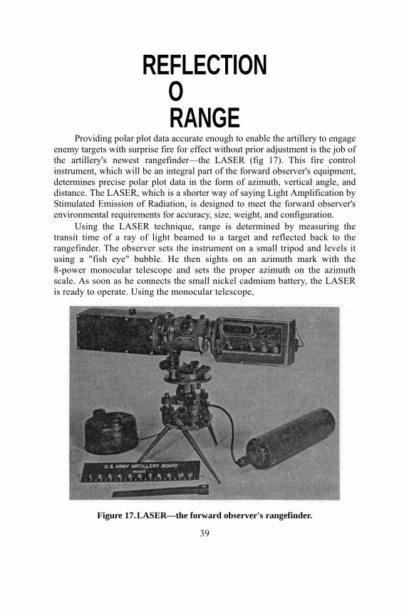
REFLECTION O RANGE
Providing polar plot data accurate enough to enable the artillery to engage enemy targets with surprise fire for effect without prior adjustment is the job of the artillery's newest rangefinder—the LASER (fig 17). This fire control instrument, which will be an integral part of the forward observer's equipment, determines precise polar plot data in the form of azimuth, vertical angle, and distance. The LASER, which is a shorter way of saying Light Amplification by Stimulated Emission of Radiation, is designed to meet the forward observer's environmental requirements for accuracy, size, weight, and configuration.
Using the LASER technique, range is determined by measuring the transit time of a ray of light beamed to a target and reflected back to the rangefinder. The observer sets the instrument on a small tripod and levels it using a "fish eye" bubble. He then sights on an azimuth mark with the 8-power monocular telescope and sets the proper azimuth on the azimuth scale. As soon as he connects the small nickel cadmium battery, the LASER is ready to operate. Using the monocular telescope,
Figure 17. LASER—the forward observer's rangefinder.
39
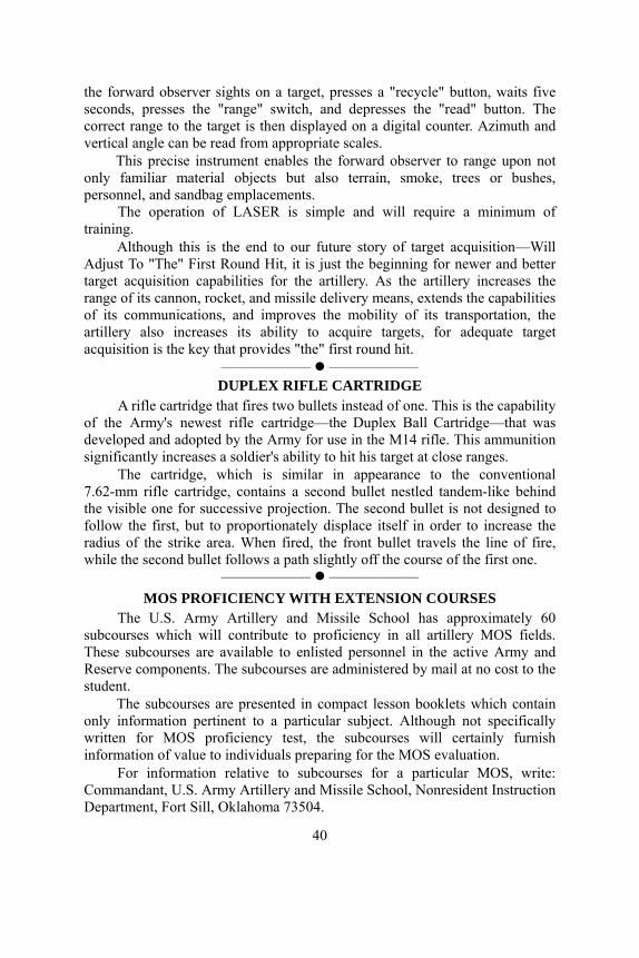
the forward observer sights on a target, presses a "recycle" button, waits five seconds, presses the "range" switch, and depresses the "read" button. The correct range to the target is then displayed on a digital counter. Azimuth and vertical angle can be read from appropriate scales.
This precise instrument enables the forward observer to range upon not only familiar material objects but also terrain, smoke, trees or bushes, personnel, and sandbag emplacements.
The operation of LASER is simple and will require a minimum of training.
Although this is the end to our future story of target acquisition—Will Adjust To "The" First Round Hit, it is just the beginning for newer and better target acquisition capabilities for the artillery. As the artillery increases the range of its cannon, rocket, and missile delivery means, extends the capabilities of its communications, and improves the mobility of its transportation, the artillery also increases its ability to acquire targets, for adequate target acquisition is the key that provides "the" first round hit.
–––––––––––– –––––––––––– DUPLEX RIFLE CARTRIDGE
A rifle cartridge that fires two bullets instead of one. This is the capability of the Army's newest rifle cartridge—the Duplex Ball Cartridge—that was developed and adopted by the Army for use in the M14 rifle. This ammunition significantly increases a soldier's ability to hit his target at close ranges.
The cartridge, which is similar in appearance to the conventional 7.62-mm rifle cartridge, contains a second bullet nestled tandem-like behind the visible one for successive projection. The second bullet is not designed to follow the first, but to proportionately displace itself in order to increase the radius of the strike area. When fired, the front bullet travels the line of fire, while the second bullet follows a path slightly off the course of the first one.
–––––––––––– –––––––––––– MOS PROFICIENCY WITH EXTENSION COURSES
The U.S. Army Artillery and Missile School has approximately 60 subcourses which will contribute to proficiency in all artillery MOS fields. These subcourses are available to enlisted personnel in the active Army and Reserve components. The subcourses are administered by mail at no cost to the student.
The subcourses are presented in compact lesson booklets which contain only information pertinent to a particular subject. Although not specifically written for MOS proficiency test, the subcourses will certainly furnish information of value to individuals preparing for the MOS evaluation.
For information relative to subcourses for a particular MOS, write: Commandant, U.S. Army Artillery and Missile School, Nonresident Instruction Department, Fort Sill, Oklahoma 73504.
40
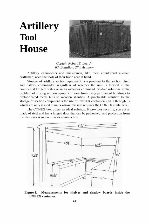
Artillery Tool House
Captain Robert E. Lee, Jr. 6th Battalion, 27th Artillery
Artillery cannoneers and missilemen, like their counterpart civilian craftsmen, need the tools of their trade near at hand.
Storage of artillery section equipment is a problem to the section chief and battery commander, regardless of whether the unit is located in the continental United States or in an overseas command. Soldier solutions to the problem of storing section equipment vary from using permanent buildings to prefabricated metal huts to wooden shanties. A practicable solution to the storage of section equipment is the use of CONEX containers (fig 1 through 3) which are only issued to units whose mission requires the CONEX containers.
The CONEX box offers an ideal solution. It provides security, since it is made of steel and has a hinged door that can be padlocked, and protection from the elements is inherent in its construction.
Figure 1. Measurements for shelves and shadow boards inside the CONEX container.
41

Figure 2. Equipment storage inside the CONEX container. Section equipment is stored on shelves and displayed on shadow boards
inside the CONEX. The chief of section can determine at a glance whether any equipment is missing. With the CONEX containers located adjacent to the weapons in the gun park, the chief of section can adequately supervise at the same time the men maintaining the howitzer and those working on the section equipment. The shelves and shadow boards are not attached to the CONEX box in any manner; instead, they are wedged in place. If the unit receives orders to move out, the shelves and shadow boards can readily be removed.
Figure 3. Equipment is readily accessible in the CONEX box (left).
Additional equipment for the prime mover is stored in a second CONEX container (right).
42

N E
W Potential For Cannon
Captain Lomax Gwathmey Test, Evaluation and Control Group
Fort Benning, Georgia
For the last several years, experiments have been conducted in the displacement of field artillery batteries by helicopter. Today, to improve on air transportable artillery, the Army is testing field artillery units specifically designed to be displaced by air vehicles. The term field artillery as applied to air assault units includes the 105-mm howitzer, Little John rocket and 2.75-inch aerial rocket helicopter units. These helicopter units provide the primary artillery support when conventional cannon fires are not available and reinforce fires when canventional cannon are available. This article concerns only the cannon artillery currently being tested in air assault operations.
In the concept of air assault operations, in which quick reaction of assault task forces to move by air and strike the enemy anywhere in the combat zone is required, elements of cannon units are employed to provide part of the firepower. These elements are organized with the 3,000-pound M102, 105-mm howitzer (fig 1) which is normally transported in CH-47 helicopters (Chinook) of the aviation group's assault support helicopter battalion. The artillery is an integral part of the assault task force which also includes combat maneuver elements, other fire support, control elements, service support elements, and transport aircraft. This force, picked up in separate assembly areas, forms into attacking posture while enroute to the objective and lands in close proximity of the objective or on it, if the objective is undefended. The cannon, being as mobile as the maneuver force, can be placed into firing positions for delivery of fires in support of the attack and in support of the consolidation of friendly forces after the attack.
43
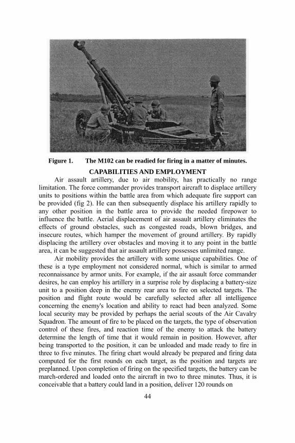
Figure 1. The M102 can be readied for firing in a matter of minutes.
CAPABILITIES AND EMPLOYMENT Air assault artillery, due to air mobility, has practically no range
limitation. The force commander provides transport aircraft to displace artillery units to positions within the battle area from which adequate fire support can be provided (fig 2). He can then subsequently displace his artillery rapidly to any other position in the battle area to provide the needed firepower to influence the battle. Aerial displacement of air assault artillery eliminates the effects of ground obstacles, such as congested roads, blown bridges, and insecure routes, which hamper the movement of ground artillery. By rapidly displacing the artillery over obstacles and moving it to any point in the battle area, it can be suggested that air assault artillery possesses unlimited range.
Air mobility provides the artillery with some unique capabilities. One of these is a type employment not considered normal, which is similar to armed reconnaissance by armor units. For example, if the air assault force commander desires, he can employ his artillery in a surprise role by displacing a battery-size unit to a position deep in the enemy rear area to fire on selected targets. The position and flight route would be carefully selected after all intelligence concerning the enemy's location and ability to react had been analyzed. Some local security may be provided by perhaps the aerial scouts of the Air Cavalry Squadron. The amount of fire to be placed on the targets, the type of observation control of these fires, and reaction time of the enemy to attack the battery determine the length of time that it would remain in position. However, after being transported to the position, it can be unloaded and made ready to fire in three to five minutes. The firing chart would already be prepared and firing data computed for the first rounds on each target, as the position and targets are preplanned. Upon completion of firing on the specified targets, the battery can be march-ordered and loaded onto the aircraft in two to three minutes. Thus, it is conceivable that a battery could land in a position, deliver 120 rounds on
44
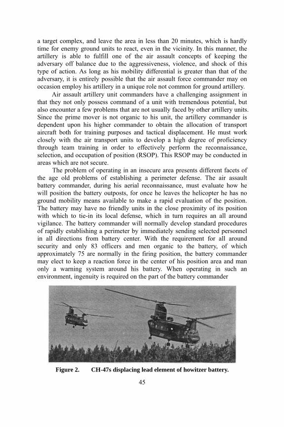
a target complex, and leave the area in less than 20 minutes, which is hardly time for enemy ground units to react, even in the vicinity. In this manner, the artillery is able to fulfill one of the air assault concepts of keeping the adversary off balance due to the aggressiveness, violence, and shock of this type of action. As long as his mobility differential is greater than that of the adversary, it is entirely possible that the air assault force commander may on occasion employ his artillery in a unique role not common for ground artillery.
Air assault artillery unit commanders have a challenging assignment in that they not only possess command of a unit with tremendous potential, but also encounter a few problems that are not usually faced by other artillery units. Since the prime mover is not organic to his unit, the artillery commander is dependent upon his higher commander to obtain the allocation of transport aircraft both for training purposes and tactical displacement. He must work closely with the air transport units to develop a high degree of proficiency through team training in order to effectively perform the reconnaissance, selection, and occupation of position (RSOP). This RSOP may be conducted in areas which are not secure.
The problem of operating in an insecure area presents different facets of the age old problems of establishing a perimeter defense. The air assault battery commander, during his aerial reconnaissance, must evaluate how he will position the battery outposts, for once he leaves the helicopter he has no ground mobility means available to make a rapid evaluation of the position. The battery may have no friendly units in the close proximity of its position with which to tie-in its local defense, which in turn requires an all around vigilance. The battery commander will normally develop standard procedures of rapidly establishing a perimeter by immediately sending selected personnel in all directions from battery center. With the requirement for all around security and only 83 officers and men organic to the battery, of which approximately 75 are normally in the firing position, the battery commander may elect to keep a reaction force in the center of his position area and man only a warning system around his battery. When operating in such an environment, ingenuity is required on the part of the battery commander
Figure 2. CH-47s displacing lead element of howitzer battery.
45

to plan his battery area defense. The battery is normally resupplied by aircraft whether or not it is
operating in an insecure area. Delivery of all classes of supply is controlled by the higher commanders. This requires the unit commanders to coordinate the time of delivery of the prepared rations, ammunition, and other supplies well enough in advance so that resupply does not coincide with displacement. This type of supply system removes some of the problems from the lower unit commander as he does not have the responsibility of dispatching trucks and appropriate security to supply points. However, he must coordinate his requests for supplies with his higher commander in order to insure delivery at the proper time. This type of resupply requires the commander to re-orient his thinking concerning resupply operations.
These differences of techniques of operating may remove some problems from the artillery unit commander while creating others. These new problems should not be insurmountable and, indeed, they may be small and insignificant when considering the potential that may exist for the employment of air assault artillery.
New horizons may be opened to the commanders of air assault field artillery for the development of tactics and techniques of employment. There exists a potential for the use of firepower on the battle field which has yet to be exploited. For the artilleryman, air assault artillery could provide a fertile field for the development of new techniques to provide the accurate fires which are the hallmark of the artillery.
–––––––––– ––––––––––
RADA COMMUNICATION SYSTEM
The Army is currently developing a new concept in communications known as RADA—the Random Access Discrete Address system. RADA can be described as a communications system in which many users can send independently different messages over a common wideband frequency channel at the same time, in the same geographical area.
In the RADA system, a single, common wideband frequency channel replaces many narrowband channels assigned to individuals or units. "Random Access" means that each user in the system has immediate access to the assigned wideband channel without delay or without coordination among other users who may be using the same channel at the same time. With RADA, many different transmissions will co-exist in the same frequency channel; therefore, the messages must be so addressed that radio receivers can distinguish messages addressed to them; this is the meaning of "Discrete Address."
The major advantage of the RADA system is no delay in transmitting messages because a user does not have to check with other users before transmitting.
46

THE PAYOFF IS ACCURACY Captain Douglas B. Stuart
Gunnery Department
In his never ending search to place more accurate and more rapid fires on the enemy, the artilleryman has turned to the digital computer for improved accuracy of cannon fire. This does not imply that our human computers have been making consistent or gross errors. Far from it. The general standard of computation in most units is quite high; however, it simply means that all computations, whether they be with a manual computer or with a digital computer, represent a compromise between an acceptable degree of accuracy and the time allowed for these computations. This article will compare the digital computer solution with the manual solution, noting the reasons for the increased accuracy of the digital computer. As such, no computer in particular will be used, although many examples will be based on experience gained with the Gun Direction Computer, M18 (FADAC).
PREDICTED FIRE
The first reason for improved accuracy of computations made by a digital computer is that it reduces the system error, which is the overall error to include the error in target location, the error at the pieces, and the error in the computation of firing data in the fire direction center. The overall system error is different from the probable error which is found in the tabular firing tables. To understand why a digital computer gives a better solution than the manual method, it is necessary to understand the limitations of the firing tables. Firing tables are not in error; in fact, they are very accurate computations. However, they are abbreviated statements of an extremely complex problem.
Before discussing the limitations of a firing table, let us consider how a firing table is made. The path of a projectile through the atmosphere can be described by the basic equations of motion for a projectile in flight. These are three simultaneous second order differential equations. The digital computers at Ballistics Research Laboratories solve these equations for standard conditions. For example; no wind, 100 percent air density, 59 degrees air temperature, and a standard weight projectile. For these conditions, the firing tables are absolutely accurate and describe the path which the projectile will follow; however, when we deviate from these conditions, corrections are necessary. Ideally, for each individual set of conditions, a new firing table should be produced for optimum accuracy. Obviously, this is not possible as a unit would require a fleet of trucks just to carry its firing tables. Therefore, a set of unit corrections are computed, and these unit corrections are then multiplied
47
manually by the amount of the deviation from standard in order to obtain a correction. This solution is essentially a linearization of what is a nonlinear function. As long as the conditions are close to standard, this approximation gives us reasonably accurate results; however, when conditions deviate widely from standard, accuracy breaks down. This is why, during the Korean War for example, the firing, using the Met plus VE technique, often showed such gross inaccuracy. Conditions there varied so widely from standard that the linearization of the firing table solution could not adequately cope with the situation.
A second reason for inaccuracy in our manual procedures is the fact that we can only apply one correction at a time. Essentially we assume that all conditions are standard except the one on which we are working at the moment. However, as we know, these conditions vary from standard at the same time, and they interact with each other. These interactions have an effect on each other and on the projectile. This effect is known as an interaction effect and is ignored in the manual solution.
Now let us consider how a digital computer solves this problem. A digital computer uses the basic equations of motion for a projectile in flight and applies the conditions to this solution as they actually exist at the time of firing. As such, the computer can be considered as generating for us a little firing table based on the conditions as they exist at the time of firing. This, of course, eliminates not only the error caused by the linearization on nonstandard effects, but also, because all effects are considered simultaneously, the error caused by the interaction effect on the projectile. It should be noted, however, that as in the computation with the firing tables, there must be a compromise of accuracy with speed for the particular computer involved. With a slower computer we must make a less precise simulation of what happens. With a faster computer we can make a better simulation. For example, the FADAC computer is a relatively slow computer, although it is much faster than a human computer. No human could possibly solve the equations of motion fast enough to support firing. However, because of its relatively slow speed, FADAC’s solution of the gunnery problem (fig 1) uses a constant integration interval throughout the trajectory.
The accuracy of the digital computer solution may be improved, however, by a closer simulation when the projectile passes through the transonic zone. As the projectile attains the speed of sound, there is a decided change in the aerodynamics affecting the projectile. The fire support system, which is a later generation of computers for the artillery, has a unique approach to this problem. As the velocity of the projectile approaches the speed of sound, the computer reduces the integration interval taking a much closer look at the conditions during this part of the trajectory. This improves its accuracy over that of the M18 Computer. This computer's faster computation time and greater memory capacity permits this more accurate solution to be done in a reasonable amount of time. The FADAC computer could use the same method; however, its solution would take too much time. Hence, although the digital computer offers a significant advantage in accuracy over the manual method
48

Figure 1. Computations used by a typical computer to solve the gunnery
problem. because of its rapidity of computations, there are even degrees of accuracy within the digital computer family according to the speed and capacity of the individual computers.
A second reason for the digital computer's increased accuracy is the manner in which it handles meteorological conditions. By going back to the basic equations of motion for a projectile in flight, the computer uses a raw met message consisting of the actual meteorological conditions from the ground level to the maximum ordinate of the trajectory. However, the manual solution solves for only one line of the met message. If a weighted message is used, the met line selected consists of the weighted average of the meteorological conditions from the ground level to that line. The line selected is based, of course, on the maximum ordinate of the trajectory. The weighted met message can introduce considerable error in the weighting factors themselves and in the averaging of effects. An example of this is a wind shear, a condition where the wind blows in one direction on one level and in opposite direction on the next level. This is an extremely severe meteorological condition. The digital computer includes this in its solution; however, in our manual techniques, it would be ignored because it is averaged out in the met message itself.
49

In order to combat these shortcomings in the manual solution, the artilleryman normally turns to registrations as a solution. As a result of a registration, corrections are based on data which actually hit a known point compared with the firing table data that should have hit that point. At other points, the registration corrections are adjusted linearally to compensate for the increase or decrease in range. This works very well within a relatively limited area known as the transfer limits.
However, these registrations have severe disadvantages. They are time consuming and of considerable intelligence value to the enemy. In addition, only limited portions of a unit's zone of responsibility can be covered from a time and an area standpoint. Experience from World War II and Korea indicates that most units conducted two registrations daily, one during the day and one after dark, with a few additional check rounds at other times. Although these few registrations do not adequately cover the zone of responsibility, the amount of ammunition expended is tremendous. The digital computer offers significant savings when compared with the manual methods just in savings of registration ammunition. To approach the accuracy of the computer with registration, coverage would require an astronomic total of 1,140 registrations daily costing over $781,000. This figure is based on a division zone 30 kilometers wide and 20 kilometers deep, transfer limits 8 kilometers wide and 4 kilometers deep, optimum use of these transfer limits, and registrations every 2 hours for best results. Obviously, no unit would expend this amount of ammunition for registrations. However, the example is cited to show what the computer offers and what is required manually to approach this.
Another reason for accuracy which the computer enjoys over a manual solution is consistency. Human computers tire, and as they do, they make more and more errors. This is not so with the digital computer. Because the computer makes so many of the computations which were formerly spread out over several members of the fire direction center, the amount of human effort is reduced to a minimum. This means first that key personnel can be rotated more often because less are required, and secondly there is less chance for human error as the amount of human computation is markedly reduced. Studies have estimated that, because of the random effect of these errors over an extended period of firing, a unit using manual computational techniques would require the expenditure of 33 percent more ammunition to get the same effect than one using a digital computer to determine firing data. This does not imply that on each mission one-third more ammunition will be required. On some missions this random error is nonexistent; however, on other targets these errors are so great that the fires would be totally ineffective.
OBSERVED FIRES So far, primarily predicted fire has been considered. What about observed
fires or situations when there is insufficient data for a predicted fire solution, which requires the elements of accurate battery location, accurate target location, meteorological data, weapon and ammunition information, and accurate computations by FADAC?
The primary advantage of a computer when all these elements are 50
not available is its ability to apply partial corrections. In its equations of motion solution, the computer can apply correctly those effects which are known; for the remainder a linear correction such as obtained from a registration must be used. As an example, with the FADAC computer, the ballistic input information is, in addition to the battery and target location, the muzzle velocity, powder temperature, projectile weight, latitude, grid declination angle, and met message. Three of these elements—the powder temperature, projectile weight, and latitude—should always be available for entry into the machine because of the ease with which they may be obtained. If the other elements are not available, a registration is necessary to provide the remaining correction. However, since part of the data is already correctly applied, the correction is smaller and the adverse effect of the linearization is substantially reduced.
When no maps are available and it is necessary to use an observed fire chart, the computer offers advantages over manual techniques. In this case, the improvements in accuracy allow a more accurate determination of altitude (the primary problem in this case) because it reduces the errors inherent with manual corrections.
ROCKET ARTILLERY Up to now the advantages of the computer have been discussed primarily
with regard to cannon artillery noting that the big improvement is one of accuracy. With rocket artillery, there is an improvement in accuracy, but the big advantage is in the timeliness of fire. This is caused by a reduction of the computation time. The reason why there is less accuracy improvement in this case is the more extensive firing tables. However, using the FADAC computer as an example, the digital computer can compute firing data in approximately 15 percent of the time it takes a human computer to come up with the same solution. Although the computation time is usually not a critical part in the overall reaction time of an Honest John or Little John unit, the digital computer frees the human from the laborious time-consuming work and permits his constant attention to the emergency type situations as they occur. In addition, the more rapid solution by the digital computer can be appreciated whenever many missions must be updated prior to firing. As an example, consider an Honest John unit which has four missions to fire in support of an attack. If a new met mesage is received just prior to firing, some very rapid computations would be required using manual techniques, and it is questionable if these latest corrections could be applied because of time involved. However, with the digital computer, these corrections can be applied within a matter of seconds. This then greatly enhances the ability of the fire direction center to keep up with the changing situation.
In conclusion the digital computer offers significant advantages over manual computation. However, as in the manual technique, computations by the computer are a compromise between accuracy required and time allotted for the computations. Because of its increased speed of computation, the digital computer provides a payoff in accuracy which enhances the artillery's ability to meet its mission of providing rapid and accurate fire to the ground-gaining arms.
51
THE ARTILLERY
WORLD USAAMS HISTORY
The history of the U.S. Army Artillery and Missile School, covering the years 1945 to present, is nearing completion. The history consists of a complete narrative and includes humorous and entertaining items along with historical fact.
Input for the volume is still welcome and would be beneficial. Artillerymen who have memories, exciting experiences, or anecdotes concerning the school or the artillery should forward such information to Commandant, U.S. Army Artillery and Missile School, ATTN: AKPSIPL-ARTILLERY TRENDS, Fort Sill, Oklahoma 73504.
RESUME OF NEW FM RADIO RANGE CAPABILITIES Artillery units, providing information on the AN/VRC-12 series of FM
radios, report excellent range results, without exception, with all vehicular and pack configurations. This information was requested by the Communication/Electronics Department, USAAMS, to determine operational effectiveness of the AN/VRC-12 series and to verify results of limited USAAMS field checks previously reported in the February 1964 issue of ARTILLERY TRENDS.
Terrain over which the radios were operated includes Fort Sill, Oklahoma, Fort Benning, Georgia, Fort Stewart, Georgia, and areas in Germany and Italy.
Although the rated range of the medium power radio set AN/VRC-46 is 24 to 32 kilometers, using the vehicular whip antenna, units at the locales indicated above report that reliable communications may be obtained at ranges of 40 to 55 kilometers. The reliable operating range of the vehicular mounted radio set may be extended to 60 to 80 kilometers by employing antenna equipment RC-292, which is issued in lieu of the developmental antenna AT-791 and/or antenna AT-1537.
The low power radio set AN/PRC-25, which has a rated range of 8 kilometers, provides reliable ranges of 16 to 24 kilometers when stationary and reasonable line of sight conditions are approximated.
The radio set AN/VRC-49 is being used extensively as an automatic retransmission station because of its reliability and ease of operation. One unit reports that the AN/VRC-49 was employed as an automatic retransmission facility for five consecutive days without difficulty.
All units using the new FM radios indicate that communication
52

capabilities are significantly increased when compared to the AN/GRC-3 through 8 family.
NEW AR 711-17 SUPPLY PROCEDURES A change in the prescribed method for requisitioning repair parts, keeping
the record of demand cards, and the initiation of a document register for supply actions was implemented into Organizational Supply Procedure by units of the active Army.
In order to minimize the internal processing and to accelerate the preparation and submission of requests for supply, Army units and supporting supply activities will use DA Forms 2765 and 2765-1. The DA Form 2765, Request for Issue or Turn-in (mechanical), which replaces DA Form 1546, is designed to initiate the request or turn-in of a single line item. The form is an 80-column single-part card designed so that certain common supply management data can be prepunched and printed. These prepunched and preprinted cards are provided to organizations for prescribed load list items and other expendable items that are ordered on a recurring basis. The DA Form 2765 is used by organizations for items classified as expendable in Department of the Army supply manuals and for all repair parts. It may also be authorized by major commanders for use in requesting nonexpendable items, provided the supply activity issues the items to the unit on DD Form 1348-1 (DOD Single Line Item Release/Receipt Document). (If a prepunched DA Form 2765 is not available, an unpunched card may be manually initiated.)
The DA Form 2765-1 (manifold copy, manual) is basically the same as the prepunched card in use. It is used to requisition items classified in supply manuals as nonexpendable except where major commanders have authorized the use of the prepunched card.
The Record of Demands Card, DA Form 2527, is designed to record quantities of repair parts obtained from a supply activity on DA Form 2765, or by direct exchange, Self Service Supply Center, or Summary Accounting of Low Dollar Turn Over Items (SALTI) Procedures. The primary purpose of the Record of Demand Card is to enable the organization to adjust quantities of repair parts authorized, based on actual demand experience. A properly prepared Record of Demand Card is placed in the visible file in each pocket containing a title insert. The card reflects the stock number, organization document number, supply source, balance on hand, quantity requested, quantity received, due in parts, and cumulative totals demanded since the last review. In the "window" of the title insert, colored tabs may be used to reflect status information on the part.
All TOE and NON-TOE organizations and activities will establish and maintain separate document registers on DA Form 2064 for expendable and nonexpendable property at each element within the organization authorized to submit supply requests to a supporting activity. The document file reflects all documents supporting equipment listed in the property book, receipt and turn-in of nonexpendable components of kits, sets, and basic issue items. Necessary postings are made to the appropriate
53
property book and the document is annotated to reflect "Posted," date of posting, and initials of the posting individual. For entries on the document register reflecting Urgency of Need Designators A or B or Issue Priority Designators 01 through 10, the unit commander or an individual specifically authorized in writing by the commander, authenticates the assignment of these priorities by placing his signature on that item of the document register for each request submitted. To prevent abuse of the system, the assignment of urgency of need or issue priority designators will be subject to review by the Inspector General.
Specific details to the establishment of these procedures are outlined in AR 711-17 (Apr 64), Stock Control Utilization and Processing of DA Forms 2765 and 2765-1, Request for Issue or Turn-in (Punched Card Series).
TAD COURSE REORGANIZATION
The Target Acquisition Department, U.S. Army Artillery and Missile School, recently has changed half of all the department's specialist courses. These changes have improved the effectiveness and efficiency of instruction presented by the Target Acquisition Department and have increased the student load without any increase in manpower, facilities or equipment. The courses that have changed and the reasons for the changes are:
● Artillery Flash Ranging Specialist (MOS 154). Because of the few spaces existing in the active army for MOS 154 (612) and the requirement that only 25 percent (153) of the TOE positions require school training, this course has been discontinued. The U.S. Army Training Center, Field Artillery, conducts Advanced Individual Training in MOS 154.0. Flash Ranging is also taught in the Target Acquisition Officer Course. It is felt that sufficient trained personnel are available from the above courses to conduct OJT at unit level.
● Warrant Officer Weather Officer (MOS 201A) and Ballistic Meteorology Equipment Mechanic (MOS 205.1). The Weather Equipment Maintenance Course, 6-N-201A/205.1, has been redesignated as the Weather Equipment Maintenance Course, 6-R-205.1. Per DA Circular 601-7, the warrant officer is required to have attended Course 6-N-205.1 prior to appointment. In the past, a prerequisite for attendance to Course 6-N-205.1 was satisfactory completion of Course 6-H-103.1. In this case, the warrant officer was fully qualified prior to appointment.
If, in the future, applicants are selected for appointment as warrant officers without attending both of the above courses, the individuals will be required to attend, as special students, the course they had not attended prior to appointment.
Because of the changes in prerequisites for the Weather Equipment Maintenance Course, it was necessary to increase the length of the course from 13 weeks, four days to 15 weeks, two days.
54

● Warrant Officer Radar Specialist (MOS 211A) and Ground Radar Mechanic (MOS 211.3). This course is redesignated Ground Radar Mechanic 6-R-211.3 and by reorganization and changing presentation, the length has been reduced from 32 weeks, two days to 26 weeks, three days. The majority of warrant officers who attended the course in the past have had basic electronics background from previous training or experience. This training is equivalent to the first 12 weeks of the course. Warrant officers with this background will be trained in phase II of the course, consisting of the last 14 weeks.
● Radar Officer Course (0140). Because of the recent reduction in TOE and TA positions for MOS 0140 in the active army, this course is being discontinued. The few remaining spaces in this MOS will be converted to MOS 1154. The technical knowledge required in the radar field can most effectively be attained by utilization of warrant officers, Mos 211A. The knowledge required for the supervisory and tactical employment role may be gained by attendance at the Target Acquisition Officers Course, 6-A-1154. In order to provide the Target Acquisition Officers with the comparative level of knowledge in radar employment currently included in the Radar Officers Course, the Target Acquisition Officers Course 6-A-1154 has been increased one week. With this increase a total of five weeks is devoted to the employment and operation of artillery radars.
● Artillery Survey Specialist Course 6-R-153.1. The Artillery Survey Specialist Course 6-R-153.1, replaced the Artillery Survey Advanced Course 6-R-153.1, reducing the length from eight weeks to five weeks, two days. The Artillery Survey Advanced Course contained advanced material that many students never used at the .1 skill level and did not contain sufficient high level training for the survey party chief or .6 skill level.
● Artillery Survey NCO Course 6-R-F34. The Artillery survey NCO Course 6-R-F34 is a new course of four weeks, two days in length and will provide the required skill and training for survey party chiefs and chief surveyors. This course will be a functional non-MOS producing course.
ANTENNA PREVENTIVE MAINTENANCE Reports from the field indicate that the antennas (AT-912/VRC) for the
AN/VRC-12 series of radios have been a problem for some units. Because of their length and the position in which they are mounted, the antennas must be kept tied down while the vehicle is moving. In some cases, this is causing the antenna RF cable, which runs through the spring on the base of the antenna, to rub against the spring. The insulation soon wears off the cable and this causes the antenna to short out. Caution should be taken to insure the cable is free of the spring when the antennas are tied down.
55

Readers’ Comments ARTILLERY TRENDS welcomes all comments from readers concerning
any information published in ARTILLERY TRENDS that would be beneficial, instructional, or informative to all artillerymen. Comments should be forwarded to: Commandant, U.S. Army Artillery and Missile School, ATTN: AKPSIPL-ARTILLERY TRENDS, Fort Sill, Oklahoma 73504.
Plotting Sheets I am an assistant advisor to a 155-mm howitzer battery. I would like to
know how this unit can obtain plotting sheets or grid sheets authorized with the Fire Direction Set, Artillery, 15,000 meter maximum range. The last two current DA Pam 310-4 have not listed any supply manuals on this item of equipment, and I would appreciate any information you might be able to furnish me.
Considering the lengths to which we have gone to try to get grid sheets, I believe other TRENDS readers could use the same information.
Staff Sergeant Rodger D. Olson Asheville Subsector Command Asheville, North Carolina
* * * * * * * * * *
Plotting sheets are Quartermaster office supplies; therefore, federal stock numbers and other information pertaining to plotting sheets are located in Department of the Army SM 10-C7510/30-ML or SM 10-C7500-IL.
For requisitioning 1/25,000 plotting sheets, the following information is provided:
● the federal stock number (FSN) for paper plotting sheets (30 × 41 1/2 inches) is 7530-281-4811. These sheets are issued 12 per package at a cost of $2.10 per package.
● the FSN for aluminum plotting sheets (47 × 35 inches) is 7530-281-4812. These sheets are issued one per roll at a cost of $4.20 a roll.
● the FSN for plastic plotting sheets (22 1/2 × 30 inches) is 7530-656-0811. These sheets are issued 24 per roll at a cost of $86.00 a roll.
● the FSN for plastic plotting sheets (35 × 47 inches) is 7530-656-0812. These sheets are issued 12 per roll at a cost of $48.00 a roll.
56
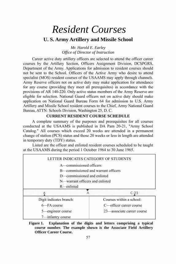
Resident Courses U. S. Army Artillery and Missile School
Mr. Harold E. Earley Office of Director of Instruction
Career active duty artillery officers are selected to attend the officer career courses by the Artillery Section, Officers Assignment Division, DCSPGRS, Department of the Army. Applications for admission to resident courses should not be sent to the School. Officers of the Active Army who desire to attend specialist (MOS) resident courses of the USAAMS may apply through channels. Army Reserve officers not on active duty may make application for attendance for any course (providing they meet all prerequisites) in accordance with the provisions of AR 140-220. Only active status members of the Army Reserve are eligible for selection. National Guard officers not on active duty should make application on National Guard Bureau Form 64 for admission to U.S. Army Artillery and Missile School resident courses to the Chief, Army National Guard Bureau, ATTN: Schools Division, Washington 25, D. C.
CURRENT RESIDENT COURSE SCHEDULE A complete summary of the purposes and prerequisites for all courses
conducted at the USAAMS is published in DA Pam 20-21, "Army School Catalog." All courses which exceed 20 weeks are attended in a permanent change of station (PCS) status and those 20 weeks or less in length are attended in temporary duty (TDY) status.
Listed are the officer and enlisted resident courses scheduled to be taught at the USAAMS during the period 1 October 1964 to 30 June 1965.
LETTER INDICATES CATEGORY OF STUDENTS
A—commissioned officers B—commissioned and warrant officers D—commissioned and enlisted N—warrant officers and enlisted R—enlisted
Digit indicates branch: Courses within a school:
6—FA course C—officer career course 5—engineer course 23—associate career course 7—infantry course
Figure 1. Explanation of the digits and letters comprising a typical course number. The example shown is the Associate Field Artillery Officer Career Course.
57

Course Class No. Report Start Close Input FA Officer Basic 5-65 13 Oct 64 16 Oct 64 17 Dec 64 91
(9 Weeks) (6-A-C20) 6-65 24 Nov 64 30 Nov 64 11 Feb 65 91 7-65 6 Jan 65 11 Jan 65 11 Mar 65 91 8-65 3 Feb 65 8 Feb 65 8 Apr 65 91 9-65 17 Feb 65 23 Feb 65 22 Apr 65 91 10-65 17 Mar 65 22 Mar 65 20 May 65 91 11-65 28 Apr 65 3 May 65 1 Jul 65 90 12-65 9 Jun 65 14 Jun 65 12 Aug 65 90
Artillery Officer Career 2-65 5 Oct 64 7 Oct 64 4 Jun 65 171 (32 Weeks) (6-A-C22) 3-65 25 Jan 65 27 Jan 65 10 Sep 65 120
4-65 3 May 65 5 May 65 17 Dec 65 120 Associate Field Artillery Officer 3-65 19 Jan 65 21 Jan 65 3 Jun 65 101
Career (19 Weeks) (6-A-C23) 4-65 26 Apr 65 28 Apr 65 9 Sep 65 101 FA Officer Refresher 3-65 31 Jan 65 1 Feb 65 12 Feb 65 39
(2 Weeks) (6-A-C6) 4-65 25 Apr 65 26 Apr 65 7 May 65 39 Senior Field Artillery Officer 2-65 3 Jan 65 4 Jan 65 15 Jan 65 24
(2 Weeks) (6-A-F6) 3-65 14 Apr 65 12 Apr 65 23 Apr 65 25 *Nuclear Weapons Employment 2-65 17 Nov 64 18 Nov 64 11 Dec 64 25
(3 Weeks) (6-A-F19) 3-65 25 Feb 65 26 Feb 65 19 Mar 65 25 4-65 3 Jun 65 4 Jun 65 25 Jun 65 15 Nuclear Weapons Employment 2-65 17 Jan 65 18 Jan 65 29 Jan 65 17
(2 Weeks) (6-A-F20) 3-65 25 Apr 65 26 Apr 65 7 May 65 17 (Res Comp)
Nuclear Weapons Employment 2-65 15 Nov 64 16 Nov 64 17 Dec 64 21 (4 Weeks, 3 days) (6-A-F26) 3-65 7 Mar 65 8 Mar 65 7 Apr 65 21
Communications Officer 4-65 2 Nov 64 3 Nov 64 4 Feb 65 35 (10 Weeks, 5 Days) 5-65 4 Jan 65 5 Jan 65 23 Mar 65 35 (6-A-0200) 6-65 1 Feb 65 2 Feb 65 20 Apr 65 35
7-65 1 Apr 65 2 Apr 65 18 Jun 65 36 8-65 3 May 65 4 May 65 21 Jul 65 36 Artillery Target Acquisition Officer 2-65 11 Jan 65 13 Jan 65 30 Mar 65 16
(11 Weeks) (6-A-1154) Artillery Survey Officer 2-65 14 Oct 64 15 Oct 64 11 Dec 64 33
(8 Weeks) (6-A-1183) 3-65 14 Apr 65 15 Apr 65 10 Jun 65 33 Sergeant Officer 2-65 13 Jan 65 14 Jan 65 24 Feb 65 24
(5 Weeks, 4 Days) 3-65 1 Mar 65 2 Mar 65 9 Apr 65 23 (6-A-1190D) 4-65 11 Apr 65 12 Apr 65 20 May 65 23
5-65 23 May 65 24 May 65 2 Jul 65 23 Sergeant Officer (Non-US) 2-65 26 Oct 64 27 Oct 64 16 Dec 64 20
(7 Weeks) (6-A-1190DX) Pershing Officer 2-65 20 Oct 64 21 Oct 64 17 Dec 64 25
(8 Weeks) (6-A-1190E) 3-65 14 Jan 65 15 Jan 65 12 Mar 65 25 4-65 CANCELLED 5-65 2 Jun 65 4 Jun 65 30 Jul 65 25 FA Officer Candidate 4-65 18 Oct 64 26 Oct 64 13 Apr 65 84
(23 Weeks) (6-N-F1) 5-65 15 Nov 64 23 Nov 64 11 May 65 84 6-65 13 Dec 64 4 Jan 65 8 Jun 65 84 7-65 24 Jan 65 1 Feb 65 6 Jul 65 84 8-65 21 Feb 65 1 Mar 65 3 Aug 65 84 9-65 21 Mar 65 29 Mar 65 31 Aug 65 84 10-65 18 Apr 65 26 Apr 65 28 Sep 65 84 11-65 16 May 65 24 May 65 26 Oct 65 84 12-65 13 Jun 65 21 Jun 65 23 Nov 65 84 * The course 6-A-F19 is conducted for selected graduates of each
Associate Field Artillery Officer Career class.
58
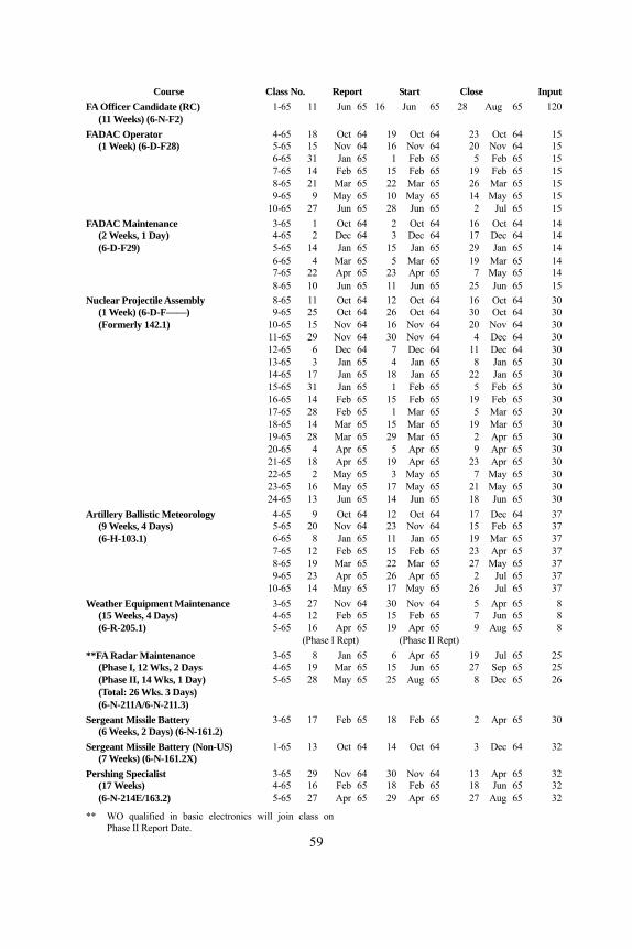
Course Class No. Report Start Close Input FA Officer Candidate (RC) 1-65 11 Jun 65 16 Jun 65 28 Aug 65 120
(11 Weeks) (6-N-F2) FADAC Operator 4-65 18 Oct 64 19 Oct 64 23 Oct 64 15
(1 Week) (6-D-F28) 5-65 15 Nov 64 16 Nov 64 20 Nov 64 15 6-65 31 Jan 65 1 Feb 65 5 Feb 65 15 7-65 14 Feb 65 15 Feb 65 19 Feb 65 15 8-65 21 Mar 65 22 Mar 65 26 Mar 65 15 9-65 9 May 65 10 May 65 14 May 65 15 10-65 27 Jun 65 28 Jun 65 2 Jul 65 15 FADAC Maintenance 3-65 1 Oct 64 2 Oct 64 16 Oct 64 14
(2 Weeks, 1 Day) 4-65 2 Dec 64 3 Dec 64 17 Dec 64 14 (6-D-F29) 5-65 14 Jan 65 15 Jan 65 29 Jan 65 14
6-65 4 Mar 65 5 Mar 65 19 Mar 65 14 7-65 22 Apr 65 23 Apr 65 7 May 65 14 8-65 10 Jun 65 11 Jun 65 25 Jun 65 15 Nuclear Projectile Assembly 8-65 11 Oct 64 12 Oct 64 16 Oct 64 30
(1 Week) (6-D-F——) 9-65 25 Oct 64 26 Oct 64 30 Oct 64 30 (Formerly 142.1) 10-65 15 Nov 64 16 Nov 64 20 Nov 64 30
11-65 29 Nov 64 30 Nov 64 4 Dec 64 30 12-65 6 Dec 64 7 Dec 64 11 Dec 64 30 13-65 3 Jan 65 4 Jan 65 8 Jan 65 30 14-65 17 Jan 65 18 Jan 65 22 Jan 65 30 15-65 31 Jan 65 1 Feb 65 5 Feb 65 30 16-65 14 Feb 65 15 Feb 65 19 Feb 65 30 17-65 28 Feb 65 1 Mar 65 5 Mar 65 30 18-65 14 Mar 65 15 Mar 65 19 Mar 65 30 19-65 28 Mar 65 29 Mar 65 2 Apr 65 30 20-65 4 Apr 65 5 Apr 65 9 Apr 65 30 21-65 18 Apr 65 19 Apr 65 23 Apr 65 30 22-65 2 May 65 3 May 65 7 May 65 30 23-65 16 May 65 17 May 65 21 May 65 30 24-65 13 Jun 65 14 Jun 65 18 Jun 65 30 Artillery Ballistic Meteorology 4-65 9 Oct 64 12 Oct 64 17 Dec 64 37
(9 Weeks, 4 Days) 5-65 20 Nov 64 23 Nov 64 15 Feb 65 37 (6-H-103.1) 6-65 8 Jan 65 11 Jan 65 19 Mar 65 37
7-65 12 Feb 65 15 Feb 65 23 Apr 65 37 8-65 19 Mar 65 22 Mar 65 27 May 65 37 9-65 23 Apr 65 26 Apr 65 2 Jul 65 37 10-65 14 May 65 17 May 65 26 Jul 65 37 Weather Equipment Maintenance 3-65 27 Nov 64 30 Nov 64 5 Apr 65 8
(15 Weeks, 4 Days) 4-65 12 Feb 65 15 Feb 65 7 Jun 65 8 (6-R-205.1) 5-65 16 Apr 65 19 Apr 65 9 Aug 65 8
(Phase I Rept) (Phase II Rept) **FA Radar Maintenance 3-65 8 Jan 65 6 Apr 65 19 Jul 65 25
(Phase I, 12 Wks, 2 Days 4-65 19 Mar 65 15 Jun 65 27 Sep 65 25 (Phase II, 14 Wks, 1 Day) 5-65 28 May 65 25 Aug 65 8 Dec 65 26 (Total: 26 Wks. 3 Days) (6-N-211A/6-N-211.3)
Sergeant Missile Battery 3-65 17 Feb 65 18 Feb 65 2 Apr 65 30 (6 Weeks, 2 Days) (6-N-161.2)
Sergeant Missile Battery (Non-US) 1-65 13 Oct 64 14 Oct 64 3 Dec 64 32 (7 Weeks) (6-N-161.2X)
Pershing Specialist 3-65 29 Nov 64 30 Nov 64 13 Apr 65 32 (17 Weeks) 4-65 16 Feb 65 18 Feb 65 18 Jun 65 32 (6-N-214E/163.2) 5-65 27 Apr 65 29 Apr 65 27 Aug 65 32
** WO qualified in basic electronics will join class on Phase II Report Date.
59
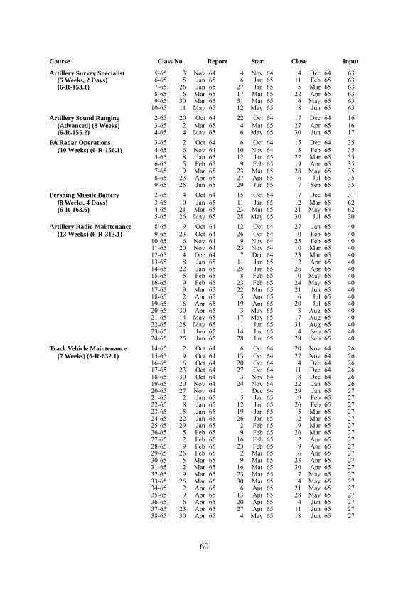
Course Class No. Report Start Close Input
Artillery Survey Specialist 5-65 3 Nov 64 4 Nov 64 14 Dec 64 63 (5 Weeks, 2 Days) 6-65 5 Jan 65 6 Jan 65 11 Feb 65 63 (6-R-153.1) 7-65 26 Jan 65 27 Jan 65 5 Mar 65 63
8-65 16 Mar 65 17 Mar 65 22 Apr 65 63 9-65 30 Mar 65 31 Mar 65 6 May 65 63 10-65 11 May 65 12 May 65 18 Jun 65 63 Artillery Sound Ranging 2-65 20 Oct 64 22 Oct 64 17 Dec 64 16
(Advanced) (8 Weeks) 3-65 2 Mar 65 4 Mar 65 27 Apr 65 16 (6-R-155.2) 4-65 4 May 65 6 May 65 30 Jun 65 17
FA Radar Operations 3-65 2 Oct 64 6 Oct 64 15 Dec 64 35 (10 Weeks) (6-R-156.1) 4-65 6 Nov 64 10 Nov 64 3 Feb 65 35
5-65 8 Jan 65 12 Jan 65 22 Mar 65 35 6-65 5 Feb 65 9 Feb 65 19 Apr 65 35 7-65 19 Mar 65 23 Mar 65 28 May 65 35 8-65 23 Apr 65 27 Apr 65 6 Jul 65 35 9-65 25 Jun 65 29 Jun 65 7 Sep 65 35 Pershing Missile Battery 2-65 14 Oct 64 15 Oct 64 17 Dec 64 31
(8 Weeks, 4 Days) 3-65 10 Jan 65 11 Jan 65 12 Mar 65 62 (6-R-163.6) 4-65 21 Mar 65 23 Mar 65 21 May 64 62
5-65 26 May 65 28 May 65 30 Jul 65 30 Artillery Radio Maintenance 8-65 9 Oct 64 12 Oct 64 27 Jan 65 40
(13 Weeks) (6-R-313.1) 9-65 23 Oct 64 26 Oct 64 10 Feb 65 40 10-65 6 Nov 64 9 Nov 64 25 Feb 65 40 11-65 20 Nov 64 23 Nov 64 10 Mar 65 40 12-65 4 Dec 64 7 Dec 64 23 Mar 65 40 13-65 8 Jan 65 11 Jan 65 12 Apr 65 40 14-65 22 Jan 65 25 Jan 65 26 Apr 65 40 15-65 5 Feb 65 8 Feb 65 10 May 65 40 16-65 19 Feb 65 23 Feb 65 24 May 65 40 17-65 19 Mar 65 22 Mar 65 21 Jun 65 40 18-65 2 Apr 65 5 Apr 65 6 Jul 65 40 19-65 16 Apr 65 19 Apr 65 20 Jul 65 40 20-65 30 Apr 65 3 May 65 3 Aug 65 40 21-65 14 May 65 17 May 65 17 Aug 65 40 22-65 28 May 65 1 Jun 65 31 Aug 65 40 23-65 11 Jun 65 14 Jun 65 14 Sep 65 40 24-65 25 Jun 65 28 Jun 65 28 Sep 65 40 Track Vehicle Maintenance 14-65 2 Oct 64 6 Oct 64 20 Nov 64 26
(7 Weeks) (6-R-632.1) 15-65 9 Oct 64 13 Oct 64 27 Nov 64 26 16-65 16 Oct 64 20 Oct 64 4 Dec 64 26 17-65 23 Oct 64 27 Oct 64 11 Dec 64 26 18-65 30 Oct 64 3 Nov 64 18 Dec 64 26 19-65 20 Nov 64 24 Nov 64 22 Jan 65 26 20-65 27 Nov 64 1 Dec 64 29 Jan 65 27 21-65 2 Jan 65 5 Jan 65 19 Feb 65 27 22-65 8 Jan 65 12 Jan 65 26 Feb 65 27 23-65 15 Jan 65 19 Jan 65 5 Mar 65 27 24-65 22 Jan 65 26 Jan 65 12 Mar 65 27 25-65 29 Jan 65 2 Feb 65 19 Mar 65 27 26-65 5 Feb 65 9 Feb 65 26 Mar 65 27 27-65 12 Feb 65 16 Feb 65 2 Apr 65 27 28-65 19 Feb 65 23 Feb 65 9 Apr 65 27 29-65 26 Feb 65 2 Mar 65 16 Apr 65 27 30-65 5 Mar 65 9 Mar 65 23 Apr 65 27 31-65 12 Mar 65 16 Mar 65 30 Apr 65 27 32-65 19 Mar 65 23 Mar 65 7 May 65 27 33-65 26 Mar 65 30 Mar 65 14 May 65 27 34-65 2 Apr 65 6 Apr 65 21 May 65 27 35-65 9 Apr 65 13 Apr 65 28 May 65 27 36-65 16 Apr 65 20 Apr 65 4 Jun 65 27 37-65 23 Apr 65 27 Apr 65 11 Jun 65 27 38-65 30 Apr 65 4 May 65 18 Jun 65 27
60

Course Class No. Report Start Close Input
39-65 7 May 65 11 May 65 25 Jun 65 27 40-65 14 May 65 18 May 65 2 Jul 65 27 41-65 21 May 65 25 May 65 9 Jul 65 27 42-65 28 May 65 1 Jun 65 16 Jul 65 27 43-65 4 Jun 65 8 Jun 65 23 Jul 65 27 44-65 11 Jun 65 15 Jun 65 30 Jul 65 27 45-65 18 Jun 65 22 Jun 65 6 Aug 65 27 46-65 25 Jun 65 29 Jun 65 13 Aug 65 27
Communications Chief 2-65 1 Dec 64 2 Dec 64 11 Mar 65 39 (12 Weeks) (6-R-F31) 3-65 1 Mar 65 2 Mar 65 24 May 65 40
4-65 1 Jun 65 2 Jun 65 25 Aug 65 40
FA Operations & 3-65 4 Jan 65 5 Jan 65 24 Mar 65 25 Intelligence Assistant 4-65 29 Mar 65 30 Mar 65 16 Jun 65 25 (11 Weeks, 1 Day) (6-R-F——) (Formerly 152.6)
***Refresher Training in the 4-65 4 Oct 64 5 Oct 64 9 Oct 64 30 Tactical Employment of 5-65 6 Dec 64 7 Dec 64 11 Dec 64 30 Nuclear Weapons 6-65 3 Jan 65 4 Jan 65 8 Jan 65 30 (1 Week) 7-65 28 Mar 65 29 Mar 65 2 Apr 65 30
8-65 2 May 65 3 May 65 7 May 65 30 9-65 13 Jun 65 14 Jun 65 18 Jun 65 30
****Artillery Survey NCO 1-65 2 Nov 64 3 Nov 64 4 Dec 64 70 (4 Weeks, 2 Days) (6-R-F34) 2-65 25 May 65 26 May 65 25 Jun 65 70
***The course is conducted for local input and instructor personnel from those installations conducting a Nuclear Weapons Refresher Course.
**** Input subject to CONARC approval. –––––––––– ––––––––––
GEM FOR FDC PERSONNEL To obtain accurate firing data, FDC computers must remember all the
computation formulas and rules. A simple device, developed by the 6th Howitzer Battalion, 31st Artillery, has eliminated some computation time for FDC computers. The device (fig 1) is a deflection-correction scale which is made on stiff paper or cardboard and shaped so that it can be glued onto the metal clip of a clipboard. The scale is covered with thin acetate, and using a black grease pencil, the computer writes in the corrections based on the most recent registrations. The elevation shown would in most cases cover transfer limits, although special situations may require extension of the scale at either end.
Figure 1. Deflection-correction scale for computers.
—Captain Donald D. Eddy 61
STATUS OF TRAINING LITERATURE AND FILMS
TRAINING LITERATURE 1. The following training literature is under preparation or
revision by the U.S. Army Artillery and Missile School or the U.S. Army Combat Developments Command Artillery Agency:
A. FIELD MANUALS (FM): FM 6-2 Artillery Survey. FM 6-3-2 Operations of Gun Direction Computer M18
(FADAC), Free Rocket Application. FM 6-3-2A(S) Gun Direction Computer M18, Cannon
Application with Nuclear Ammunition. FM 6-10 Field Artillery Communications. FM 6-15 Field Artillery Meteorology. FM 6-20-1 Field Artillery Tactics. FM 6-39 Field Artillery Battalion, Pershing. FM 6-60 Field Artillery Rocket, Honest John with
Launcher M289. FM 6-81 155-mm Howitzer M1, Towed. FM 6-88 155-mm Howitzer M109, Self-Propelled. FM 6-94 175-mm Gun M107, Self-Propelled and 8-inch
Howitzer M110, Self-Propelled. FM 6-115 Field Artillery Searchlight Battery. FM 6-140 Field Artillery Battalions and Batteries. FM 6-141 Doctrine for Effective Use of Nonnuclear
Artillery Weapons, Part II. FM 6-161 Radar Set, AN/MPQ-4A.
B. ARMY SUBJECT SCHEDULES (ASUBJSCD): ASubjScd 6-3 Cannoneer and Launcher Crewman Instruction. ASubjScd 6-4 Combat Intelligence. ASubjScd 6-23 Sound Ranging Set, GR-8.
C. ARMY TRAINING PROGRAMS (ATP): ATP 6-100 Army Training Program for Field Artillery Units. ATP 6-302 Field Artillery Missile Units, Honest John and
Little John. ATP 6-575 Field Artillery Target Acquisition Battalion.
2. Training literature submitted for publication: FM 6-40 Field Artillery Cannon Gunnery. (Changes 2) FM 6-40-1 Field Artillery Rocket Gunnery. FM 6-40-1A (S) Field Artillery Rocket Gunnery. *FM 6-40-2 (C) Field Artillery Missile Gunnery. FM 6-40-3 Field Artillery M18 Computer, Gunnery.
62

FM 6-77 105-mm M52, Self Propelled. (Changes 1)
FM 6-93 8-inch M55, Self-Propelled. FM 6-122 Artillery Sound and Flash Ranging. FM 20-60 Battlefield Illumination. FM 21-13 The Soldier's Guide. TM 6-300-65 Army Ephemeris.
*FM 6-40-2 (C) to supersede FM 6-50. ASubjScd 6-32 Field Artillery Command Post Exercises. ASubjScd 6-42 Difficult Traction and Field Expedients. ASubjScd 6-147 Field Artillery Rocket Crewman, MOS 147.1. ASubjScd 6-152 Field Artillery Operations and Intelligence
Assistant, MOS 152.1. ASubjScd 6-153 Artillery Surveyor, MOS 153.0. ASubjScd 6-154 Flash Ranging Crewman, MOS 154.0. ASubjScd 6-155 Sound Ranging Crewman, MOS 155.0. ASubjScd 6-163 Field Artillery Missile Crewman (Pershing),
MOS 163.0/.1. 3. Training literature recently printed:
FM 6-3-1 Operations of Gun Direction Computer M18 (FADAC), Cannon Application.
FM 6-70 105-mm Howitzer, M102. FM 105-6-1 (C) U.S. Nuclear Play Calculator. FM 105-6-2 U.S. Nuclear Play Calculator. FM 105-6-3 Aggressor Nuclear Play Calculator. ASubjScd 6-29 Artillery Survey.
TRAINING FILMS 1. The following training films are currently under production and
scheduled for release during calendar year 1964: Field Artillery Target Acquisition Battalion. Operation of the Surveying Instrument Azimuth Gyro Artillery. Fire Direction Procedures—Part I. Precision Fire (TF 6-3448)—Part II. Area
Fire (TF 6-3449)—Part III. Observed Fire (TF 6-3450). Defense of the Field Artillery Battery (Active and Passive). Pershing Missile System—Air Transported and Track Mounted Operations. 2. The following training films are currently under production and
scheduled for release during calendar year 1965: The Sergeant Artillery Guided Missile System. Communication Systems of the Direct Support Artillery Battalion. The Pershing Missile Azimuth Laying Procedure. 3. Training films scheduled for production and release during
calendar year 1965: Helicopter Artillery RSOP—Part I and II. Fire Support Coordination for the Infantry Division.
63

Pershing Missile Assembly—Part I. Mounted—Part II. Dismounted. Weapons of the Field Artillery (Color TF 6-2804). Operation of the Gun Direction Computer M18. Measuring Distance with DME, MC-8. 4. Training films recently released to Audio Visual Communications
Center: The Honest John Battalion—Part I. Organization and Operations (TF
6-3436)—Part II. RSOP (TF 6-3451).
–––––––––––– ––––––––––––
SCHOOL HISTORY
Following are two samples of the humorous and entertaining items which will be incorporated in the history of the U.S. Army Artillery and Missile School (1945 to 1964) presently being prepared by the USAAMS (See Newsnote, page 52). Artillerymen remembering similar incidents are encouraged to send them to Commandant, U.S. Army Artillery and Missile School, ATTN: AKPSIPL—ARTILLERY TRENDS, Fort Sill, Oklahoma 73504.
" . . . . Actually, instructors soon became familiar with the technique of teaching Korean students through an interpreter. Most instructors enjoyed teaching the Korean officers because of the undivided attention they gave the instructor. To make studying easier for the Korean students, the school published Instructional Notes in Korean. On more than one occasion these notes created humorous incidents. Several times, the instructor of a regular course was startled to have an American student complain that he couldn't read the instructional note issued to him. Examination revealed that a Korean note had inadvertently been issued.
"Once, an instructor in the Department of Communication, having knowledge of a "friend" in one of the Basic Officer Courses, caused an entire set of instructional notes in Korean to be issued to his friend. The resultant uproar precluded any further stunts of that type."
“ . . . . Two wire-team members of a Fort Sill unit developed their own method of laying wire. One hot, sultry day, the two were laying wire on the West Range when they came to a culvert. Their chief directed that the wire be run through the culvert so it would be out of the way of vehicles and other traffic. The two couldn't figure out how to get the wire through the culvert, since it was too small for them to crawl through. Suddenly, they hit upon an idea, as they saw a rabbit scamper into some brush behind them.
"In a few minutes, they had caught the rabbit, tied the end of the wire to its tail, and placed the rabbit at their end of the culvert. Naturally, the rabbit, in its anxiety to get away, scampered through the culvert, pulling the wire behind it.
"The Department of Communications didn't incorporate this 'new' method in its program of instruction, however."
L 1136 ARMY-FT. SILL, OKLA.
64