articulated robot ra605 - hiwin · c01ue001-1502 2 do not stand or put heavy objects on the product...
TRANSCRIPT

Articulated Robot – RA605
Manipulator Manual
C01UE001-1502
1
Safety and Notice
1. Safety Information
a. This safety information neither contains how to design, install and run a complete
workstation or production line, nor ensure the whole system safety
b. All machines must be designed and installed according to the industrial safety regulations to
guarantee user safety
c. HIWIN robot users have the responsibility to design and install safety devices that are in
compliance with industrial safety regulations
d. This manual can help prevent but not guarantee safety hazards
e. Besides the built-in safety loop, the robot also provides an interface for an external safety
device, which can receive external signals that provides additional control
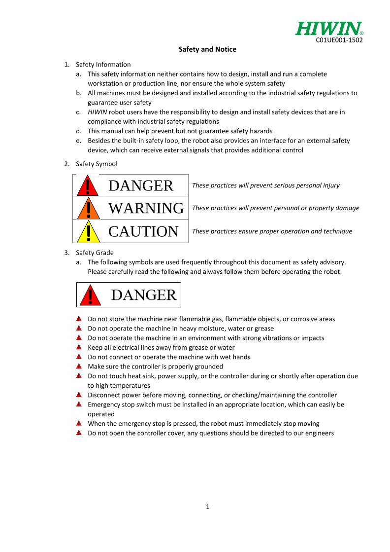
2. Safety Symbol
DANGER These practices will prevent serious personal injury
WARNING These practices will prevent personal or property damage
CAUTION These practices ensure proper operation and technique
3. Safety Grade
a. The following symbols are used frequently throughout this document as safety advisory.
Please carefully read the following and always follow them before operating the robot.
Do not store the machine near flammable gas, flammable objects, or corrosive areas
Do not operate the machine in heavy moisture, water or grease
Do not operate the machine in an environment with strong vibrations or impacts
Keep all electrical lines away from grease or water
Do not connect or operate the machine with wet hands
Make sure the controller is properly grounded
Do not touch heat sink, power supply, or the controller during or shortly after operation due
to high temperatures
Disconnect power before moving, connecting, or checking/maintaining the controller
Emergency stop switch must be installed in an appropriate location, which can easily be
operated
When the emergency stop is pressed, the robot must immediately stop moving
Do not open the controller cover, any questions should be directed to our engineers

C01UE001-1502
2
Do not stand or put heavy objects on the product
Do not block the outlet or put foreign objects on it
Ensure the robot is securely fixed onto the base
Do not pull or twist the electric wires
Do not repeatedly toggle any of the on/off switches
Ensure that the robot emergency stop switch and the controller are functioning properly
before performing any work
Do not shut off the power during robot operation
Do not open, modify, disassemble or maintain the machine without consulting with HIWIN
engineering
Turn the power off if the robot won’t be operating again soon
All operations must be executed by trained staff members
The controller must be kept away from high voltage or components that may generate
electromagnetic fields, because this can lead to malfunction or damage
When doing test runs, keep the speed low and watch the operating conditions to prevent any
unforeseen dangers
Do not turn the power off to the controller when modifying programs/parameters. This will
damage the data stored in the controller or result in data loss
4. Safety Risks
a. Installation
i. Ordinary Risk
1. Standard installation procedures demonstrated in this manual must be followed
2. The emergency stop switch must be installed at an easily operable location
3. The person who installs the robot must be trained and authorized
4. Always follow the installation and safety requirements described in this manual
to ensure personal safety
ii. Risk Without Electric Shock
1. A safety area must be set outside the working range of the robot, and a safety
device must be used to prevent unauthorized entrance within the working range
2. After the servo motor brake is released, the robot may move due to gravity
3. When installing/disassembling any mechanical parts, be aware of falling parts
which may hurt the operator
4. Be aware of high temperatures produced by the controller
5. Do not allow any climbing of the robot
b. End Effector
i. The end effector can be classified as two types:
1. Gripper: Used to load and unload. These are typically pneumatic, hydraulic,
electric, or vacuum.
2. Tool: Used to compete a process. For example, welding, cutting, grinding, surface
treatment, etc.

C01UE001-1502
3
ii. The gripper-type end effector should prevent the workpiece from dropping or
damaging when the robot encounters a power error or other errors (determined in
the design phase)
iii. The end effector could be equipped with the control unit. The position must be noted
to avoid robot interference
c. Pneumatic and Hydraulic Systems
The tool-type end effector is usually equipped with high voltage, high temperature, or moving parts. Special attention should be paid during operation. Pressure in pneumatic and hydraulic systems may run several times higher than atmospheric pressure.
i. Be sure to relieve the pressure in pneumatic/hydraulic systems after the power is
disconnected
ii. Internal pressure must be released before the pneumatic/hydraulic systems are
maintained
iii. While pneumatic/hydraulic systems are operating, the clamped workpieces can be
dropped due to insufficient working pressure
iv. Pneumatic/hydraulic systems must be equipped with a relief valve, for emergency
situations
d. Working Environment Risks
i. The industrial robots can be modified for the different industrial environments
ii. All operating procedures must be specified under professional evaluation and
according to the industrial safety regulations
iii. Maintenance must be conducted by trained personnel who clearly understand the
procedures for the entire system and the risks associated
iv. When the operating procedures are interrupted, pay close attention during
troubleshooting
e. Emergency Stop
i. When pressed, motor power is cut off
ii. When pressed, all actions are stopped and the control system disconnects
iii. To restart operating procedures, the emergency stop switch must be reset and the
emergency error must be cleared on the pendant
iv. Emergency stop performs an immediate stop, by cutting all power to the motors
v. If the brakes are not applied on joints, the robot may fall by its own weight
vi. The emergency stop switch is used for emergency only
vii. Avoid using the emergency stop instead of the normal stop
viii. The HIWIN robot is equipped with two emergency stop switches; one is installed on
the teach pendant, and the other is directly connected to the controller via the wires
ix. If other emergency stop switches are required, other connections can be installed for
the same purpose
x. Based on the relevant industrial safety regulations, the emergency stop switch is
directly connected to the controller of the robot via physical wires

C01UE001-1502
4
Contents 1. Introduction ................................................................................................................................................ 5
1.1 Product Specifications ........................................................................................................................... 5
1.2 Appearance Dimension/Motion Range ................................................................................................ 6
1.3 Load Rating of Robot End ...................................................................................................................... 7
1.4 Robot and Accessories .......................................................................................................................... 8
2. Unpack and Install ....................................................................................................................................... 9
2.1 Unpack .................................................................................................................................................. 9
2.2 Transportation .................................................................................................................................... 10
2.3 Installation .......................................................................................................................................... 11
2.4 Ground Procedure ............................................................................................................................... 12
2.4.1 Grounding .................................................................................................................................... 12
2.5 Installation of Controller ..................................................................................................................... 12
3. Teach Pendant Usage ................................................................................................................................ 13
3.1 Installation of Teach Pendant ............................................................................................................. 13
3.2 Coordinate System .............................................................................................................................. 13
4. End Effector ............................................................................................................................................... 14
5. Maintenance and Check ............................................................................................................................ 16
5.1 Maintenance and Check Interval ........................................................................................................ 16
5.2 Internal Maintenance and Inspection ................................................................................................. 17
5.2.1 Robot Structure ............................................................................................................................ 18
5.2.2 Install and Remove Robot Cover .................................................................................................. 19
5.2.3 Belt Maintenance ......................................................................................................................... 20
5.2.4 Lubrication ................................................................................................................................... 25
5.2.5 Replacing Backup Battery ............................................................................................................ 26
5.3 Maintenance ....................................................................................................................................... 27
5.4 Calibrating Home Position .................................................................................................................. 27
5.4.1 Set first axis home ........................................................................................................................ 28
5.4.2 Set second axis home ................................................................................................................... 28
5.4.3 Set third axis home ...................................................................................................................... 29
5.4.4 Set fourth axis home .................................................................................................................... 29
5.4.5 Set fifth axis home ....................................................................................................................... 30
6. Appendix ................................................................................................................................................... 31
6.1 Appendix I ........................................................................................................................................... 31
6.2 Appendix II .......................................................................................................................................... 32

C01UE001-1502
5
1. Introduction
1.1 Product Specifications The product specifications are shown in Table 1-1.
Table 1-1: Product Specifications
Model No. Unit RA605-710
Freedom 6
Load capacity kg 5
Maximum Motion Radius mm 710
Working Range
J1*
Degrees
±165
J2* +85 ~ -125
J3* +185 ~ -55
J4 ±190
J5 ±115
J6 ±360
Standard Cycle Time** sec 0.50
Repeated Accuracy mm ±0.02
Tolerant Torque
J4
N-m
8.46
J5 8.46
J6 5.6
Tolerant
Rotation Inertia
J4
kg-m2
0.35
J5 0.35
J6 0.14
Wrist Line 6 Input Point & 4 Output Point
Pneumatics φ4×2 (AIR IN & AIR OUT)
Connection Line m 3m (between robot and controller)
Controller RCA605
Weight kg 40 (not including controller)
*Joint one, joint two, and joint three’s movement is limited by a mechanical stopper **The cycle time is the time it takes the robot to move 25mm vertically, 300 mm horizontally, then -25 mm vertically, while holding 1 kg. The movement is shown in figure 1-1.
Figure 1-1: Cycle Time Trajectory

C01UE001-1502
6
1.2 Appearance Dimension/Motion Range The appearance dimensions and motion range are shown in Figure 1-2 and Figure 1-3.
Figure 1-2: Appearance Dimensions
Figure 1-3: Motion Range

C01UE001-1502
7
1.3 Load Rating of Robot End The load rating of the robot end not only limits the weight but also the position of gravity when the load’s center of gravity varies. Figure 1-4 shows the allowed position of gravity, when the load varies from 1kg to 5kg.
Figure 1-4: Illustration of Load Geometry
The transportable load weight is greatly related to the motion position and speed of the robot. This could produce a current overload even in the allowable range of the load. When this situation occurs, the position and speed will be changed.

C01UE001-1502
8
1.4 Robot and Accessories The RA605 package comes with a lot of accessories! Besides the physical robot, there are cables, calibration tools, emergency stop buttons, etc. A complete list of accessories is shown in table 1-2. Following that is an optional list of accessories, which are explained later in the catalog.
Table 1-2: Accessory List
No. Name Model No. Quantity Comments
1 Calibration Set 1 Home calibration
2 Set of Fixing Plates 1 Fixing for robot
3 Stylus Pen 1
4 End I/O Connector PLT-1112-PM 1 For end I/O
5 Main Power Line CN1 1
6 Motor Signal Line CN2 1
7 Signal Connection 1
8 Controller Key 2
9 Cotton Core 2 For controller inlet
10 Set of Emergency Stop Switch 1
Table 1-3: Optional List
No. Name Model No. Quantity Comments
1 Suspension Plate for Transportation 1
2 Base of Robot 1
3 Lithium Battery 6
4 Set of Mechanical Stops for axis 1 1

C01UE001-1502
9
2. Unpack and Install
2.1 Unpack The package of the robot that the customer receives is shown in Figure 2-1. The following procedures to unpack must be followed when the robot is unpacked:
Figure 2-1: Package Diagram
Step 1: Cut and remove the package strips Step 2: Remove the box, as shown in Figure 2-2 (a)
Figure 2-2 (a): Unpacking step 2 Figure 2-2 (b): Unpacking step 3
Step 3: Take out the accessory kit (A), instruction device (B) and controller (C) from the cartons, as shown above in Figure 2-2(b) Step 4: Remove the front plate that fixes the robot, as shown in Figure 2-2(c)
Figure 2-2 (c): Unpacking step 4 Figure 2-2 (d): Unpacking step 5
Step 5: Remove the back plate that fixes the robot, as shown in Figure 2-2(d). Unpacking is a success!

C01UE001-1502
10
2.2 Transportation
If the robot is being transported after taking it out of the box, please follow these steps and list of materials to ensure safe handling.
Table 2-1: Transportation Materials
Quantity Component
2 Suspension Plates* (Appendix I)
4 Screws
4 Eye Bolts & Nuts
*The suspension plates are optional components
Steps:
1. Fix the suspension plate to the robot with the provided screws, as shown in Figure 2-3
Figure 2-3: Installation of the Suspension Plate
2. Fasten the eye bolts to the suspension plate and hook a rope through each eye bolt 3. Lift the robot onto the installation surface, as shown in Figure 2-4
Figure 2-4: Front (left) and Side (right) view of the robot being transported using the
shipping and suspension plates
After removing the plates, properly store them for future use
Angle for suspended robot: A1 0°, A2 45°, A3 -55°, A4 0°, A5 -80°, A6 0°
If the arm is directly suspended without using the specified suspension plate, it will cause damage due to a misaligned center of gravity
Use safe practices while transporting, and avoid excessive vibration or shock during transportation

C01UE001-1502
11
2.3 Installation
After the robot is placed on the installation surface, remove the suspension and fixing plate. Then fix the robot to the installation surface using M10 socket head cap screws, spring washers, and flat washers. The dimensions of the robot base are shown in Figure 2-4.
Figure 2-5: Installation Diagram
Figure 2-6: Illustration of base dimensions
Do not install the robot in areas of heat exposure (direct sunlight, excessive lighting, heaters, etc.)
Make sure the installation surface has been leveled and has a roughness below 6.3a (if it is too rough the robot could shift position during an operation)
Ensure the position of the installation surface is fixed
Ensure the installation surface will not get damaged due to the robots movement
If robot is installed on ceiling or wall, parameters must be changed Please contact engineering if this is the case

C01UE001-1502
12
2.4 Ground Procedure
2.4.1 Grounding There are three grounding types shown in Figure 2-7. All three are acceptable, however the best grounding system is to ground the robot and controller individually (shown in figure 2-7 (a)).
Figure 2-7 (a): Figure 2-7 (b): Figure 2-7 (c):
Grounding (excellent) Common Grounding (Good) Common Grounding (General)
Grounding Components: A grounding wire over AWG#11 (4.2mm2) is used to connect the robot and the grounding area. The hardware needed for the connection consists of a screw, spring washer, and flat washer. The proper grounding is shown below in figure 2-8.
Figure 2-8: Grounding Line Diagram
Keep the length of the grounding wire as short as possible, by keeping the grounding point close to the robot
The grounding wire of the robot should be a separate wire than those from other equipment
2.5 Installation of Controller The illustration of installing the controller and the robot in shown in Figure 2-9.
Figure 2-9: The robot (left) is connected to the controller (right) via the cable

C01UE001-1502
13
3. Teach Pendant Usage
3.1 Installation of Teach Pendant The picture below is showing how to install the teach pendant to the controller.
Figure 3-1: Teach Pendant (left) gets plugged directly into the controller (right)
3.2 Coordinate System There are two coordinate systems for the robot, Articulated, and Cartesian. The Articulated Coordinate System presents the robot’s position by using the rotational angle of each axis (A1, A2, A3, A4, A5 and A6), as shown in Figure 3-2.
Figure 3-2: Articulated Coordinate System

C01UE001-1502
14
The Cartesian Coordinate System displays the robot’s position with X, Y, Z, RX, RY and RZ coordinates. There are the ROBOT, TOOL and BASE Coordinates in the Cartesian coordinate system, as shown in Figure 3-3. In the program, RX is represented as A, RY as B, and RZ as C.
Figure 3-3: Cartesian Coordinate System
ROBOT Coordinate is based on the robot as home TOOL Coordinate is the home at the sixth axis flange coordinate to define as the TOOL Coordinate system
BASE Coordinate System is at the position of workpiece and based on the ROBOT Coordinate System
4. End Effector Many types of tool and grippers can be attached via electrical interfaces, or with pneumatics through a double solenoid valve. Some examples are an electric clamp, burr removal module or welding tool. This tool that gets attached through the robot can then be accessed through the controller and teach pendant. There are six M5x0.8 I/O interface and electromagnetic valves at the end connector of the robot, as shown in Figure 4-1.
Figure 4-1: Connector for the robot end (A is outlet, B is inlet)

C01UE001-1502
15
The pin assignment of the I/O pins is shown in figure 4-2. Before soldering I/O pins, separate the front-
end of the I/O terminal from the housing. Users can connect corresponding pins based on the demand.
Figure 4-2: I/O Pin Assignment
If the wires attaching to the end effector are either getting tangled, wrapped or just unorganized,
consider fixing them near the fifth axis joint (see figure 4-3).
Figure 4-3: Securing wires using a fixed plate
To do this, unscrew the desired screw that attaches to the Hiwin plate (using a torx wrench). Then tighten
the fixed plate in between the screw and the face of the robot. This will limit how much the wire can wrap
around the robot. The exact dimensions of the fixed plate can be seen in Appendix II.

C01UE001-1502
16
5. Maintenance and Check This chapter will introduce the methods and the steps for preventative maintenance. This will include cover removal and installation, internal maintenance, belt checks and replacements, lubrication, battery replacement, and home calibration.
5.1 Maintenance and Check Interval The maintenance and check can be classified into two categories; daily checks and the periodic checks. The daily checks include the power on/off and operation, representing those before the power on/off and programming respectively, as shown in table 5-1. The periodic checks include those for the routine check A, B, C, D and E. The check contents are shown in table 5-2. The timetable can be worked out according to the periodical check, as shown in Figure 5-1. When these checks are done correctly, unnecessary troubles will be avoided and the robot can be operated for extended durations of time safely.
Table 5-1: Daily Inspection Points
Inspection points Solution
Inspection Before Turing the Power ON
1 Are any screws loose on the robot system? Tighten the screws 2 Is the power supply cable securely connected? Reconnect
3 Are the robot and controller connected? Reconnect 4 Are there any cracks or foreign contamination? Clean/Replace Part 5 Are there any air leaks, clogging or hose damage in the pneumatic
system? Is the air source normal? Clear drainage and replace the leaking parts
Inspection After Turning the Power ON 1 Is there any unusual motion or noise when the power is ON? Refer to the troubleshooting
manual
Inspection During Operation
1 Do the fixed parts of robot move?
Refer to the troubleshooting manual
2 Is there any unusual motion or sound? Refer to the troubleshooting manual
Table 5-2: Periodic Inspection Points
Inspection points Solution Monthly Inspection Points (item A)
1 Are any of the screws on the manipulator loose? Tighten the screws
2 Are any of the connector fixing screws or terminal block screws loose? Tighten the screws
Quarterly Inspection Points (item B)
1 Check if the tension of each axes timing belts is abnormal has changed Refer to 5.2.3.
Biannual Inspection Points (item C)
1 Is the friction at the timing belt teeth severe? Refer to 5.2.3
Annual Inspection Points (item D)
1 Replace the backup battery in the manipulator Refer to 5.2.5
3-Year Inspection Points (item E) 1 Fill lubricant for axis decelerator Refer to 5.2.4

C01UE001-1502
17
Figure 5-1: Maintenance schedule
5.2 Internal Maintenance and Inspection
This section will introduce the belt maintenance, lubrication and battery replacement. Please read the contents carefully, and follow the descriptions for all maintenance. The parts that customers check and maintain will be described in 5.3 Maintenance. If needed, please contact HIWIN engineers.
Don’t remove any part not described in this manual without consulting HIWIN engineers
After any of the following maintenance replacements/adjustments occur, the robot must be recalibrated because any of the axis may have moved and have lost their home position
C01UE001-1502
18
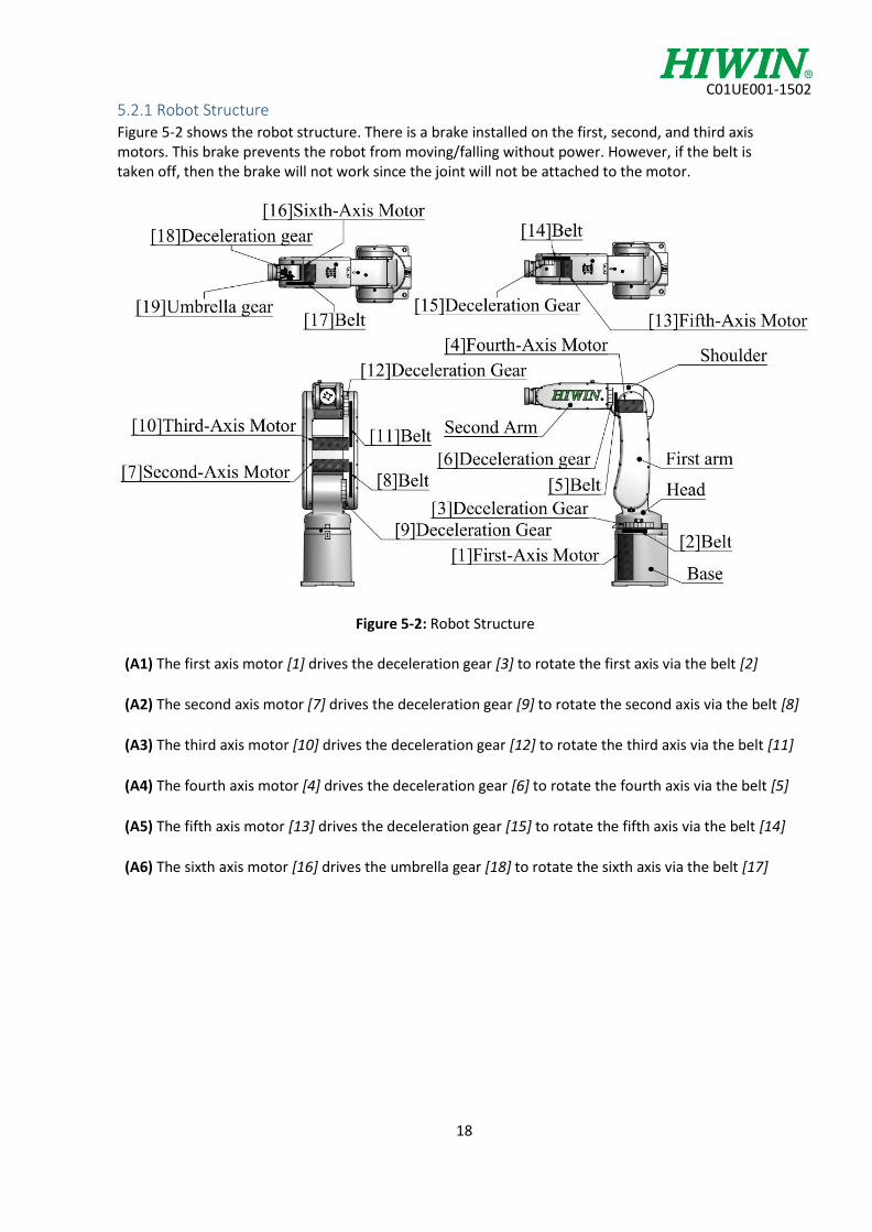
5.2.1 Robot Structure Figure 5-2 shows the robot structure. There is a brake installed on the first, second, and third axis motors. This brake prevents the robot from moving/falling without power. However, if the belt is taken off, then the brake will not work since the joint will not be attached to the motor.
Figure 5-2: Robot Structure
(A1) The first axis motor [1] drives the deceleration gear [3] to rotate the first axis via the belt [2]
(A2) The second axis motor [7] drives the deceleration gear [9] to rotate the second axis via the belt [8]
(A3) The third axis motor [10] drives the deceleration gear [12] to rotate the third axis via the belt [11]
(A4) The fourth axis motor [4] drives the deceleration gear [6] to rotate the fourth axis via the belt [5]
(A5) The fifth axis motor [13] drives the deceleration gear [15] to rotate the fifth axis via the belt [14]
(A6) The sixth axis motor [16] drives the umbrella gear [18] to rotate the sixth axis via the belt [17]

C01UE001-1502
19
5.2.2 Install and Remove Robot Cover Before removing/installing the robot cover, please return the robot to the home position. Figure 5-3 shows the exploded view of the robot, with covers removed. The screws are listed in Table 5-4.
Figure 5-3: Exploded View of Robot
Table 5-4: List of cover screws
Symbol Specification Quantity
[a] Torx M3x12 10
M3 washer 10
[b] Torx M3x12 10
M3 washer 10
[c] Torx M3x8 9
M3 washer 9
[d] Torx M3x8 9
M3 washer 9
[e] Torx M3x8 4
M3 washer 4
[f] Torx M3x6 4
M3 washer 4
[g] Torx M3x8 5
M3 washer 5

C01UE001-1502
20
5.2.3 Belt Maintenance The purpose of the belt on the robot is to have a drive without lubrication that creates a low amount of
noise. The belt tension has been adjusted prior to the robot being shipped. The belt will irregularly loosen
or stretch due to operation conditions, the tension should be periodically checked, maintained and
replaced.
5.2.3.1 Replace timing belt
Depending on robot conditions, the time to replace the belt will vary. If the following situations take place, the belt must be replaced:
The belt teeth has severe cracks
The belt has expanded
The belt has significant wear (to approx. half of the tooth width)
The belt has deviation or misalignment
The belt has a large amount of friction
5.2.3.2 Belt Tension
When the belt is properly tensioned, it will drive as intended and improve durability. When the belt is adjusted to a certain extent, you can feel the flexibility with your finger. If the belt is too loose, it will vibrate; on the contrary, if it is too tight, you will hear a sharp sound, and the belt will excessively wear. The tension can be measured hand or tool. Fasten the belt to a certain extent and then release with a tension meter, as shown in Figure 5-4. The specifications of each axis belt are shown in Table 5-5.
After the robot has operated for around 300 hours, some belt material may be seen on the cover. This doesn’t mean it will fail, but it should be wiped down, then replaced the next time the buildup is observed
When the belt is replaced, the robot home could shift. In this situation the position data must be checked again. If it is shifted, recalibrate the robot
Figure 5-4: Belt Tension Diagram

C01UE001-1502
21
Table 5-5: List of the tension of the timing belt
Axis Model No. Pitch (mm) Belt width (mm) Mass (g) Tension (N)
Second axis 370-5GT-9 370 9 4 200-250
Third axis 440-5GT-9 440 9 4 200-250
Fifth axis 285-3GT-6 285 6 2.5 50-70
Sixth axis 285-3GT-6 285 6 2.5 50-70
If the first axis and the fourth axis need to replace the belt, contact HIWIN Engineers
5.2.3.3 Second Axis Belt Maintenance
Figure 5-5 shows the illustration of the second axis structure.
Figure 5-5: Second axis belt structure
Check second axis belt:
1. Disconnect the power 2. See 5.2.2 to remove the second axis cover (first arm) 3. Check the belt for significant wear or markings 4. If the belt needs replacing, please see the following to adjust the second axis belt
Adjusting second axis belt tension: 1. Lightly loosen the three screws for the motor plate [1] 2. Loosen the tension nut [6], and then adjust the tension screw [3] 3. After the tension is adjusted, tighten the tension nut [6] 4. Tighten the three screws for the motor plate [1]
a. The belt could shift and loosen if they are not tightened after adjustment
Replace second axis belt: 1. Lightly loosen the three screws for the motor plate [1], then remove 2. Loosen the tension nut [6] and the screws [3], and remove the old belt 3. Install the new belt, and see Adjust Second axis Belt to adjust the belt 4. The home position needs to be recalibrated, since the motor and brake were disconnected from
the axis (See 5.4 to recalibrate the home)

C01UE001-1502
22
5.2.3.4 Third axis Belt Maintenance
Figure 5-6 shows the illustration of the third axis structure.
Figure 5-6: Third axis belt structure Check third axis belt:
1. Disconnect the power 2. See 5.2.2 to remove the third axis cover (first arm) 3. Check the belt for significant wear or markings 4. If the belt needs replacing, please see the following to adjust the third axis belt
Adjusting third axis belt tension: 1. Remove the screw plate (connects the third and second axis motor plate to tension the second
axis) 2. Lightly loosen the three screws for the motor plate [1] 3. Loosen the tension nut [6], and then adjust the tension screw [3] 4. After the tension is adjusted, tighten the tension nut [6] 5. Tighten the three screws for the motor plate [1]
a. The belt could shift and loosen if they are not tightened after adjustment
Replace third axis belt:
1. Lightly loosen the three screws for the motor plate [1] 2. Loosen the tension nut [6] and the screws [3], then remove the old belt 3. Install the new belt, and see Adjust third axis Belt tension to adjust the belt 4. The home position needs to be recalibrated, since the motor and brake were disconnected from
the axis (See 5.4 to recalibrate the home)

C01UE001-1502
23
5.2.3.5 Fifth axis Belt Maintenance
Figure 5-7 shows the illustration of the fifth axis structure.
Figure 5-7: Fifth axis belt structure
Check fifth axis belt:
1. Disconnect the power 2. See 5.2.2 to remove the fifth axis cover (right case of the second cover, even though the left case
is shown) 3. Check the belt for significant wear or markings 4. If the belt needs replacing, please see the following to adjust the third axis belt
Adjusting fifth axis belt tension: 1. Lightly loosen the two screws for the motor plate [1] 2. Loosen the tension nut [6], and then adjust the tension screw [3] 3. After the tension is adjusted, tighten the tension nut [6] 4. Tighten the two screws for the motor plate [1]
a. The belt could shift and loosen if they are not tightened
Replace fifth axis belt:
1. Lightly loosen the two screws for the motor plate [1] 2. Loosen the tension nut [6] and the screws [3], then remove the old belt 3. Install the new belt, and see Adjust fifth axis Belt tension to adjust the belt 4. The home position needs to be recalibrated, since the motor was disconnected from the axis (See
5.4 to recalibrate the home)

C01UE001-1502
24
5.2.3.6 Sixth axis Belt Maintenance
Figure 5-8 shows the illustration of the sixth axis structure.
Figure 5-8: Sixth axis belt structure
Check sixth axis belt:
1. Disconnect the power 2. See 5.2.2 to remove the sixth axis cover (left case of the second arm) 3. Check the belt for significant wear or markings 4. If the belt needs replacing, please see the following to adjust the sixth axis belt
Adjusting sixth axis belt tension: 1. Lightly loosen the two screws for the motor plate [1] 2. Loosen the tension nut [6], and then adjust the tension screw [3] 3. After the tension is adjusted, tighten the tension nut [6] 4. Tighten the two screws for the motor plate [1]
a. The belt could shift and loosen if they are not tightened after adjustment
Replace sixth axis belt:
1. Lightly loosen the two screws for the motor plate [1] 2. Loosen the tension nut [6] and the screws [3], then remove the old belt 3. Install the new belt, and see Adjust sixth axis Belt tension to adjust the belt 4. The home position needs to be recalibrated, since the motor was disconnected from the axis (See
5.4 to recalibrate the home)

C01UE001-1502
25
5.2.4 Lubrication
5.2.4.1 Inlet and Outlet Positions and Lubrication Specification
Figure 5-9 shows the inlets and outlets. The lubrication specifications are shown in Table 5-6. See 5.2.2
before installing/removing any covers.
Figure 5-9: Lubrication Position
Table 5-6: Lubrication specification
Lubrication Nozzle
Dimensions Lubricant
Weight [g]
Time [hr]
Use [g]
Remove cover
First axis deceleration gear M5x0.8*6 HRG-01 52.5
24000
8
Second axis deceleration gear M5x0.8*6 HRG-01 45 8 Remove J1 axis cover
Third axis deceleration gear M5x0.8*6 HRG-01 24 4 Remove J1 axis cover
Fourth axis deceleration gear M5x0.8*6 HRG-01 19.5 4
Fifth axis deceleration gear M5x0.8*6 HRG-01 13.5 2
Sixth axis deceleration gear M5x0.8*6 HRG-01 9.15 2
5.2.4.2 Notice for Lubricant Supply
The lubrication time is the overall time the robot spends traveling at the maximum speed o If the robot holds or operates at the slow speed, the lubrication time can be linearly
extended
Do not allow the robot to run without lubrication
Re-lubrication interval is typically around 3 years
If the full lubrication is required, please contact us to avoid excessive lubrication leakage

C01UE001-1502
26
5.2.4.3 Lubrication Method
1. Figure 5-9 (page 25) shows the position to lubricate the robot 2. See 5.2.2 to remove the cover 3. Cover the belt to prevent any contact with the lubrication 4. Loosen the lubrication screws, and connect the nozzle 5. Tighten the nozzle between 3N-m to 4.4N-m 6. Remove the outlet lubrication screws 7. Fill lubricant from lubrication nozzle with the filler 8. After lubricant is filled, reinstall the outlet screws 9. Disconnect the nozzle and reinstall the lubrication screws 10. See 5.2.2 to install the cover
5.2.5 Replacing Backup Battery Absolute encoders are used to record the position. When the power is disconnected, the power from the backup battery will be active to record the current position of the encoders. Depending on the operating conditions, the back-up battery should be replaced every year to maintain functionality. When the battery is low, the customer should replace the batteries immediately. Figure 5-10 shows the method to replace the battery. The procedures to replace the battery are described as below:
Figure 5-10: Battery replacement
1. Make sure the robot and controller are fully connected 2. Before new batteries are installed, press the emergency stop switch to kill all power leading
to the robot 3. Unscrew the battery cover [1] and take the old batteries out 4. Replace each battery one at a time with new batteries 5. All batteries must be replaced in one sitting, and an old/new batteries combination will
cause excess heat 6. After the batteries are replaced, reinstall the battery cover onto the battery box
Lubricant is filled at 0.03MPa when manually operating the filler
Don’t use the factory filler to avoid excessive pressure
If all batteries are removed at once, the data stored in the encoders will be lost and the robot will have to be recalibrated

C01UE001-1502
27
5.3 Maintenance Table 5-7 shows the parts which will be periodically replaced. These accessories are available through Hiwin.
Table 5-7: Parts list
No. Name Specification Location Quantity
1
Belt
270-5GT-9 J1 axis 1
2 370-5GT-9 J2 axis 1
3 440-5GT-9 J3 axis 1
4 216-3GT-6 J4 axis 1
5 285-3GT-6 J5 axis 1
6 285-3GT-6 J6 axis 1
7 Lubricant EK3 Deceleration gear for
each axis 1
8 Lithium battery No. 3, 3.6V One-time lithium battery 2.4A In battery box 6
5.4 Calibrating Home Position Fixture Home Method: There is a fixture for home calibration in the accessory kit, which is used for the calibration of the first to fifth axis. The robot is adjusted to the minimum speed during the calibration. There are different pinholes and keyway seats for each individual axis, which must be lined up. The calibration tools are shown below in figure 5-11.
Figure 5-11: Calibration Kit (requires 2.5mm and 3mm Allen wrenches)
The following are the illustrations to calibrate the first 5 axis. To successfully calibrate the sixth axis, a
combination of a level and a flat tool or mounting plate must be used. The plate would be mounted to the
robot end effector.

C01UE001-1502
28
5.4.1 Set first axis home To calibrate the first axis, the calibration plate must be installed to the base of the robot, seen in figure 5-12. The first axis is adjusted with the minimum speed until the tab is flush with the fastened calibration plate.
Figure 5-12: First axis home calibration
5.4.2 Set second axis home The second axis calibration is accomplished by rotating the second axis at minimum speed until the pinhole on the first arm is concentric with the pinhole of the robot base. The calibration rod can then be set to the origin position. Then the second axis is calibrated, as shown in Figure 5-13.
Figure 5-13: Second axis home calibration

C01UE001-1502
29
5.4.3 Set third axis home The third axis calibration is accomplished by rotating the third axis at minimum speed until the pinhole on the second arm is concentric with the pinhole of the first arm. The calibration rod can then be set to the origin position. Then the third axis is calibrated, as shown in Figure 5-14.
Figure 5-14: Third axis home calibration
5.4.4 Set fourth axis home The fourth axis calibration is accomplished by rotating the fourth axis at minimum speed until the calibration groove on the second arm is aligned with the calibration groove of the twisting arm. The calibration key can be placed and into the calibration groove, or origin position. Then the fourth axis is calibrated, as shown in Figure 5-15.
Figure 5-15: Fourth axis home calibration

C01UE001-1502
30
5.4.5 Set fifth axis home The fifth axis calibration is accomplished by rotating the fifth axis at minimum speed until the pinhole on the second arm is concentric with the pinhole of the fifth axis and the calibration rod can be set to the origin position. Then the fifth axis is calibrated, as shown in Figure 5-16.
Figure 5-16: Fifth axis home calibration

C01UE001-1502
31
6. Appendix
6.1 Appendix I Suspension Plates for transporting the robot (refer to 2.2)

C01UE001-1502
32
6.2 Appendix II The fixed plate used to control the directions and orientations of wires connecting to the end effector.

C01UE001-1502
33
Hiwin Corporation 1400 Madeline Lane Elgin, Illinois 60124 United States Tel: (847) 827-2270 www.hiwin.com
The specifications in this catalog are subject to change without notification