article1379947252_ragab radial drilling
TRANSCRIPT
8/12/2019 Article1379947252_ragab Radial Drilling
http://slidepdf.com/reader/full/article1379947252ragab-radial-drilling 1/15
Vol. 4(5), pp. 103-117, May, 2013
DOI 10.5897/JPGE2013.0153
ISSN 2141-2677 © 2013 Academic Journals
http://www.academicjournals.org/JPGE
Journal of Petroleum and Gas
Engineering
Full Length Research Paper
Improving well productivity in an Egyptian oil fieldusing radial drilling technique
Adel M. Salem Ragab
Department of Petroleum Engineering, School of Sciences and Engineering (SSE), American University in Cairo (AUC),Egypt.
Department of Petroleum Engineering, Faculty of Petroleum and Mining Engineering, Suez University, Egypt.
Accepted 22 April, 2013
Radial drilling (RD) technique utilizes hydraulic energy to create several lateral holes in differentdirections and levels with several lengths. These lateral holes are made by milling the casing with smallbit then extending these holes laterally using high pressure hydraulic jetting. This work presents fulldescriptions and analysis for RD applications in one of the Egyptian oil field. Moreover, it attempts toanalyze and then optimize the different means for performing this technique. Therefore, several testswas performed and analyzed. The total depths of these wells vary from 8856 to 8987 ft. The first wellwas laterally drilled by about 164 ft long by seven laterals and the angle between each two is 90°. Thesecond well was drilled by 6 laterals in two different levels. Five of them extended to 164 ft, and one ofthem with 295 ft long. In the third well, 4 lateral holes were radially drilled with 165 ft long. Afterevaluation, the first well gross rate increased by 37.4%, and the net oil rate was improved by more than31.4%; the second well shows an improvement by about 73.34% increase in gross rate, and 47.3%, an
increase in the net oil rate; and the third well shows an improvement by about 14.3% gross rate, and14.7%, an increase in the net oil rate for very short period. Several experiences have been gained fromusing this technology which extends the productive life of wells and accordingly of the whole field withreasonable cost.
Key words: Radial drilling, stimulation, lateral holes, hydraulic jetting, URRS.
INTRODUCTION
The well is drilled and then completed to move the oil andgas from its original location in the reservoir to thesurface, and due to damage during drilling and
completion operation, not all of these fluids can move tothe area around the wellbore, therefore, it is alwaysimportant to think about any unconventional means toreach or communicate these areas with the wellbore.One of the proposed techniques is to bypass thedamaged zone which is called radial drilling (RD).
The objective of the radial drilling is to provide anextended wellbore radius by means of multiple radialsfrom a vertical wellbore. It can be applied both in new and
old wells. It is mainly used as high pressure jet flowenergy to penetrate and elongate a number of lateraholes radiated from the main wellbore in the same laye
or different layer. The choice of radial length, number oradials, and radial array is a function of the reservoirproperties.
Radial drilling
The radial drilling (RD) is a technique that can createseveral small diameter drains from the well in a relatively
E-mail: [email protected]
8/12/2019 Article1379947252_ragab Radial Drilling
http://slidepdf.com/reader/full/article1379947252ragab-radial-drilling 2/15
104 J. Petroleum Gas Eng.
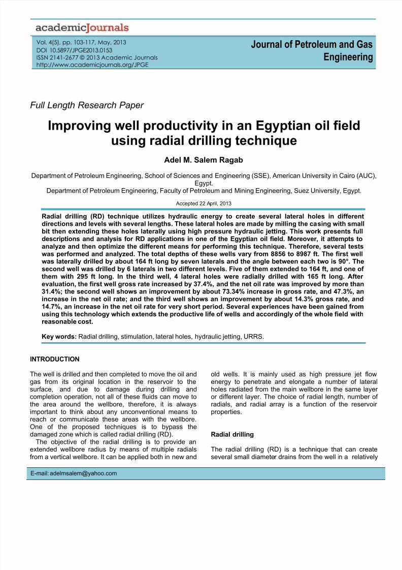
Figure 1. Radial drilling technique.
short time, normally 2 to 3 days per level. The diameter ofthese holes varies from few millimeters to several tenthsof millimeters in the casing using high pressure fluid atselected depths and azimuth, and installed at single ormultiple levels. These perforations can be extendedradially up to 100 m perpendicular from the mainwellbore, as shown in Figure 1. The first application ofthis technique had been performed in former SovietUnion (Elliott, 2011).
Working principle of radial drilling
The features of the tool are the capability to create andopen a hole in the casing and subsequently jettinglaterally into the reservoir formation creating a lengthyhole to bypass the damaged zone around the well whichis called altered or skin area. To perform this, a specialbottom hole assembly (BHA) which consists of a drillingmachine; high pressure hose, and jet nozzle have beenassembled. The drilling machine involves a drill bit drivenby a combination of an electrical motor and a hydraulicpiston, making a hole in the casing, its size depends onthe bit size used. Then jetting through this hole may
extend this hole to 100 m ( 330-ft), based on the hoselength.
The components of the tool used in radial drillingmainly consist of the drilling machine and the jet drum. Inaddition, as depicted in Figure 1, it involves the followingcomponents:
(i) Tubing end connector(ii) Controller unit/power pack(iii) Anchor(iv) Orienter/Indexer(v) Steering-tool(vi) Stroke cylinder.
Applications
The main application is to provide a fast and economicamethod to recover the remaining hydrocarbons formmarginal or mature oil and gas fields.
This technique can be applied in different disciplines inoil well industry such as:
1. Well completions

8/12/2019 Article1379947252_ragab Radial Drilling
http://slidepdf.com/reader/full/article1379947252ragab-radial-drilling 3/15
2. Well stimulations3. Directed reservoir treatment4. Improve water injection5. Improve vertical cleaning6. Reduce water coning7. New wells instead of standard completion methods
8. Water disposal and re-injection9. Steam applications in heavy oil and tar sands10. Mining applications (leaching).
Radial drilling benefits
Based on what have been performed on some worldwidefields, the radial drilling methods have some economicaland technical benefits such as (Bruni et al., 2007;Dickinson-Dickinson, 1985):
1. Enhance production rate and recoverable reservesfrom marginal wells.2. Improves injection rates in water disposal/injectionwells.3. Allows directional treatment of wells for example, acid,steam, CO2, etc.4. Outperforms conventional stimulation methods at alower cost, in reduced application time and with higherpotential production results.5. Improved and extended drainage area in productiveformations.6. Radial drilling penetration greatly exceedsconventional (perforation) penetration and can reachsubstantially beyond the damaged area of the well-bore.7. Reach beyond the damaged area of the well-bore.
8. Allows multi-layer application in thicker reservoir zones.9. Most effective on old, low productivity wells.10. No need for large, expensive rotary rigs.11. Does not require mud pits that can damage theenvironment.12. No casing milling requirement, therefore no need tocirculate mud back to the surface.13. No additional stimulation required.14. The process is fast, average operation duration is twodays per well, so no big loss in production.15. No logging expense required.16. No need to change well-bore configuration.
Limitations of radial drilling
Based on the previous operations using radial drilling allover the world, there are some limitations and challengesin applying such technique in oil and gas wells (Abdel-Ghany et al., 2011). From these:
1. Difficulties of penetration under porosity of 3 to 4%.2. Maximum working depth about 10000 ft.3. Bottom hole temperature not to exceed 120°C (248°F)
Ragab 105
4. Maximum wellbore inclination 30° and no more than15° at the zone target depth/zone of interest.5. Maximum tensile strength 100,000 psi.
Radial drilling field operations
Bruni et al. (2007) show a brief description of theoperation and bottom hole assembly of radial drillingtechnology. Radial drilling technique is described as anew coiled tubing convoyed drilling technique, wereseveral new wells or lateral holes are jet drilledperpendicular from the mother well and into the reservoirformation, this technology is targeted for increasing thewell productivity of the new and existing wells.
The following is a brief procedure for performing this jobin a specific well (Figure 2):
1. Run in hole with deflector sub on drill pipe stringcorrelating its depth with well logging.2. Orient string with gyro.3. Run in hole with milling tool (milling bit).4. Pull out of hole with milling tool.5. Run in hole with jetting tool.6. Pull out of hole with hose, nozzle jetting tool.7. Rotate deflector shoe and repeat operation at eachlateral hole for any horizontal layer.
In another way, the radial drilling technology can beperformed in three main steps, first step is milling thecasing , second step is jetting the formation with highpressure nozzle and the last one is washing out the
formation while pull out of hole. Figure 2 illustrates thesesteps.
The bottom hole assembly for milling the casing are1¾” bit connected with flexible shaft, both are rotated byconventional mud motor connected to coiled tubing up tosurface, connected to coiled tubing unit with itsmonitoring system. Figures 3 to 5 show the bottom holeassembly for milling the casing.
The created hole size depends on formation strengthconfining strengths and compressive loads fromoverburden and matrix stress, as well as on the speed openetration of the jet. From surface tests an average holesize of 4 to 5 cm in diameter was obtained.
MECHANISM OF PENETRATION
It is reported in the literatures (Bruni et al., 2007; Buset eal., 2001) that there are four main penetrationmechanisms. These mechanisms are: 1) surface erosion2) hydraulic fracturing; 3) poroelastic tensile failure; and4) cavitation.
The net forces that affect to drive jetting nozzle forwardcan be derived from three main mechanisms; unde

8/12/2019 Article1379947252_ragab Radial Drilling
http://slidepdf.com/reader/full/article1379947252ragab-radial-drilling 4/15
106 J. Petroleum Gas Eng.
Figure 2. The three steps for radial drilling process.
Figure 3. Deflector shoe with flexible shaft inside.
Figure 4. The 1¾” bit connected to flexible shaft
Figure 5. The 1 ¾” bit and the flexible shaft connected to motor.
pressure force, jetting force and ejector force. The mainmechanism is jetting force mechanism; Figures 6 and 7show the driving mechanisms of jetting nozzle and ieffect of core sample.
The BHA is gathered and then circulating with anintermediate flow rate; once the BHA is close to the baffleshoe, the flow rate is increased and the tool is slippedallowing for the introduction into the anchor. Once thehose enters the formation, it will move horizontally in theformation due to the force generated by the distribution o

8/12/2019 Article1379947252_ragab Radial Drilling
http://slidepdf.com/reader/full/article1379947252ragab-radial-drilling 5/15
Ragab 107
Figure 6. Sketch of the nozzle.
Figure 7. Jet nozzle of 8000 psi and its effect in core sample.
jet nozzles. The force S in the driving direction can becalculated from the following equation:
Where: Ao = Inside hose area (m
2)
Ai = Nozzle area (m2)
uo = inside hose velocity (m/s)
ui = Nozzle velocity (m/s) = Density of water (kg/m
3)
= Angle of the nozzle.
WORLDWIDE FIELD APPLICATIONS
In 1985, Dickenson-Dickenson described a new systemto drill horizontal holes of 100 to 200 ft in length, andabout 4 inches in diameter, through an unconsolidatedformation in Californian oil field. Then placing a 1¼ inchOD production carbon steel tube within the 4 inch
8/12/2019 Article1379947252_ragab Radial Drilling
http://slidepdf.com/reader/full/article1379947252ragab-radial-drilling 6/15
108 J. Petroleum Gas Eng.
diameter bore hole in the formation while drilling is inprogress. The drill system uses 8000 to 10000 psi water
jet drilling causes a velocity ranges from 6 to 120 ft/min.They mentioned that this drilling system is not limited tohorizontal shallow, 100 to 200 foot radials, it is neitherlimited to a 1¼ inch production tube nor a 4 inch radial
bore. The system can work vertically and can be place invery long and large tubes, moreover, it can be applied inoffshore reservoirs, consolidated formations, wastedisposal and mineral recovery by solution mining.
In 1989, Dickenson et al. extended their previous worknot by elongating the depth of penetration but byincreasing the number of radials, they named it ultra-short radius radial system (URRS). Multiple radials canbe placed at the same level and on multiple levels andhorizontal completions can be provided, including 100%gravel packing, in-situ electrolytic perforation and cutting,and flexible sand barriers (FSB's). Initial field applicationswere in unconsolidated formations. The basic URRSuses an erectable whip stock lowered down hole by a 4½inch work string into an under reamed cavity orhydraulically slotted opening of 22 inch diameter. Thesurface water drilling fluid pressure ranges from 8000 to10000 psi which is pumped into the long vertical workstring with a conventional fracture pump (Dickinson et al.,1989).
Dickinson et al. (1992) presented for the first time theuse of combination of water jet drilling and coiled tubing,URRS and quick radial system (QRS) provide multiplehorizontal radials on a single horizon near wellbore.These have been done by milling of casing and underreaming of a cavity. The hardware of the URRS includeswhipstock, drilling string, jet drilling, control while drilling,
positional survey, cutoff and perforation, gravel packing,slotted liner, and gravity drainage.
Yonghe et al. (2000) described the application anddevelopment of using URRS by high pressure jet flowtechniques, and applied this technique for two wells.They described the details of the operation in which theyperformed radial holes with lengths ranged from 4 to 10m. They concluded first, that this technique can greatlyincrease oil recovery and oil production rate and secondit needs some improvement to solve some problemsbefore the large scale uses.
Marbun et al. (2011) reported herein discusses theapplication of the URRS. The specific variables like
reservoir thickness, vertical and horizontal permeabilities,oil properties, well spacing, outer-boundary reservoirpressure, gravity drainage, thermal and non-thermalprocesses and impermeable partings within the reservoirhas been studied together with drilling operationparameter like casing design, drilling fluid design, radialdrilling equipment, Bottom Hole Assembly to optimize thedrilling process and completion of the URRS at field.
In the North Urtabulak Oil Field in southern Uzberkistan(Bruni et al., 2007), a trail program was conducted in fiveexisting wells using radial drilling, a coiled tubing
workover technique in which lateral holes of 2-indiameter are drilled up to 330 ft from the original welbore by high pressure water jetting. All but one of the fivetrials wells displayed significant post workover uplift inproduction, leading to overall incremental production omore than 17000 bbl in 2011.
Buset et al. (2001) in his paper titled “Jet Drilling ToolCost-Effective Lateral Drilling Technology for EnhancedOil Recovery” addressed a new coiled tubing (CTconveyed drilling technique, were several new wellboresare jet-drilled perpendicular from the mother well and intothe reservoir formation. Their objective is to improve theproduction profile around the mother well, by penetratingthe damaged skin zone, and connecting to possiblehydrocarbon pockets left behind in the reservoir. Theydescribed mathematically the new CT tool in terms of thePenetration Effect, and pull effect. The first effect which ispenetration mechanisms were Identified by SurfaceErosion, Hydraulic Fracturing, Poroelastic tensile failureand Cavitation. The second effect, the net pull effect thatworks the nozzle forward can be derived from three mainmechanisms: the under pressure force, the jetting forceand the ejector force. Finally, they concluded that furtherresearch and testing of the jet nozzle penetrationmechanism are required in order to identify the optimanozzle configurations.
Elshahawi et al. (2001) presented several case studiesperformed in Belayim Fields of Sinai, Petrobel-Egypt toenhance their production. The main reasons for tryingthis new technique were the reduction in the wellsproductivity, and the rapid decline in total field productionThe major wells in this field were under artificial liftingand this involved the integration of data from various
sources. They showed in their study that the majority ofwells in the field were suffering from severe damageUsing nodal analysis and skin modeling, the wells werethen categorized based on the value of their completionfactors (the ratio of actual to theoretical productivityindices), and the potential sources of damage wereidentified for each category.
The method used to mitigate this shortage in the wellsproductivity is to deep penetrating perforating chargesthis had been performed after investigating the origin andthe development of formation damage in Belayim Fieldsand how this damage was attributed to different damagemechanisms using a novel combination of nodal and
damage analysis techniques.Elshahawi et al. (2011) addressed several methods fo
damage removal such as vacuum strings (for perforationcleaning), surging using an atmospheric chamber (failed)acidizing (failed), demulsifiers and other chemicals tobreak emulsions (failed), and finally Deep-penetratingperforating. The later technique in Petrobel was the mossuccessful productivity enhancement over the last fewyears. The main reasons for this success are to increasethe surface area available for flow, decrease pressuredrop and thus reduce the flow velocity across the

8/12/2019 Article1379947252_ragab Radial Drilling
http://slidepdf.com/reader/full/article1379947252ragab-radial-drilling 7/15
perforated interval. And present three cases illustratinghow deep penetrating perforating has been successfullyused to remove well damage and increase wellproductivity, namely Well BM-30 m, Wells Sidri-3 andSidri-4, and Well Sinai-02.
FIRST CASE OF RADIAL DRILLING APPLICATION INEGYPT
This technique was applied for the first time in Egypt inBelayim Land Oil Field in Petrobel Company (Dickinsonet al., 1989). The formation of the Belayim Oil Field islocated in the central part of the Gulf of Suez along SinaiPeninsula. Belayim oil fields are characterized by multiplelayered reservoirs generally formed from sand with inter-bedded shale and anhydrite from different ages. Belayimoil field main production now depend on artificial lift;secondary recovery are used (water injection).
The data of the first job are collected and analyzed inorder to decide extending this technique to more otherwells in the company. Many considerations had beentaken into account for well selection. From theseconsideration, open hole logs for defining the pay zones,lithology, static bottom hole reservoir pressure, averageporosity (about 20%) and permeability, cased hole logsand casing types and grades. Based on all of thementioned parameters three wells were selected toevaluate radial drilling technique from layered reservoirzones II-A and IV. Currently, Zone IV contains about 23%of Belayim OOIP and contributes about more than 27%of production.
This technique is applied in three wells, in the first one,
which was producing a commingle from two zones(Belayim and Sidri), six lateral drains at two levels wasperformed, five of which are 50 m long and one penetrateabout 92 m long, all oriented by gyro tool. In the secondwell, seven laterals have been performed in Sidriformation, all penetrate 50 m long each at one differentdepth and oriented like a spiral by rotating the BHA at thesurface one and half turn. The last well, four lateral areperformed at two different depths, all are 50 m long(Abdel-Ghany et al., 2011).
In 2011, Abdel-Ghany et al. presented someexperience gained from using this technique andconcluded that; for one well, an increase in the rate of 75
to 130 m3
/day, for the second one, the production rate isincreased from 41 to 45 m
3/day, and for the last well, the
results showed no change in flow rate.
RESULTS
Case 1: Well # 1
Well #1 is produced from two different zones (zone II-Aand zone IV) with an average daily rate of 251 bpd, the
Ragab 109
current static reservoir pressure is about 900 psi andproductivity index is 2 barrel per day per psi, theformation porosity 20% in average, the rock permeabilityis varied largely, the total depth of this well is about 8856ft and net pay thickness is 82 ft. Figure 8 illustrates thecasing and perforation interval of that well. This wel
radially drilled on 2010 to evaluate and optimize thistechnique in the field.Radial drilling job were performed on this well by milling
and jetting seven lateral holes with 164 foot lateral lengthat different depths from zone IV as shown in Figure 8The hydraulic jet pressures for all of them were 7000 psi.Table 1 shows the accurate depths and elongations foreach lateral.
While performing RD in this well, a vacuum test wasperformed before and after radial drilling job to evaluatethis technique. Production rate shows an increased afterstimulating the well with this technique. The grossproduction rate increased from 252 to 346 bpd, where thenet oil rate increased from 220 to 289 bpd, which means37.5% increase for the gross rate and 31.4% for the neoil rate. Figures 9 to 11 show the results of vacuum testsbefore and after jobs. Table 2 shows comparisonbetween rate before and after radial drilling job, andFigure 12 displays gross production performance beforeand after applied radial drilling technique. As shown inthat figure, the rate maintained awhile after performingthe test and then declined again but still better thanbefore conducting the technique. This is attributed to ‘donot fill the hole with any material’ and that can keep thechannel open in order to guarantee constant productionrate.
Case II: Well #2
This well is produced from three zones (zone II, II-A andzone IV) with average daily production rate 471 bpd, itscurrent static reservoir pressure is about 1990 psi at topof perforation 7126 feet sub sea level and productivityindex is 1 barrel per day per psi from last vacuum tesbefore applied radial drilling, its rock porosity is 20%heterogeneous permeability, the total depth of this well is8134 ft and net pay thickness is 133 ft. Figure 13illustrates casing and perforation interval for well #2.
Radial drilling job was performed on this well by milling
and jetting six lateral holes at two depths with 164 ftlateral length and one of them was 295 ft lateral lengthfrom zone II-A. Table 3 shows the full details of the sixlaterals performed in well #2. In the previous well, thelateral holes were drilled randomly but here in this welthe lateral hole selection was based on geological mapsand faults orientation so holes were made at two depthsand oriented with consideration to north direction.
A vacuum test was performed on this well before andafter radial drilling job to evaluate this techniqueProduction rate obviously show increase after stimulating

8/12/2019 Article1379947252_ragab Radial Drilling
http://slidepdf.com/reader/full/article1379947252ragab-radial-drilling 8/15
110 J. Petroleum Gas Eng.
Figure 8. Casing and perforation sketch of well #1.
Table 1. Radial drilling operation performed on well #1.
No. of hole Hole depth (ft) Penetration length (ft) Jetting pressure (Psi) Remarks
1 7675.20 164 7000
2 7671.92 164 70003 7668.64 164 (L) 7000
4 7665.36 164 (L) 7000
5 7662.08 164 (L) 7000
6 7658.80 *** 7000 Tried two times to drill, no success 7 7655.52 164 7000
During POOH found the bit and flexshaft in side deflector shoe
8 7652.24 164 7000
(L): Lateral.

8/12/2019 Article1379947252_ragab Radial Drilling
http://slidepdf.com/reader/full/article1379947252ragab-radial-drilling 9/15
Ragab 111
P I ( b p d / p
s i )
Time (min)
B H P
( p s i )
Figure 9. Fill-up test for BHP and P.I test before RD of well #1.
Time (min)
P I ( b p d / p s i )
p s
Figure 10. Fill-up test for BHP and P.I test after radial drilling.
P I ( b p d / p s i )
Time (min)
B H P
s i
Figure 11. BHP comparison between the two tests before and after RD.

8/12/2019 Article1379947252_ragab Radial Drilling
http://slidepdf.com/reader/full/article1379947252ragab-radial-drilling 10/15
112 J. Petroleum Gas Eng.
Table 2. Comparison between the rate before and after RD.
Before radial drilling After radial drilling
Rate (bpd) WC (%) Net oil Rate (bpd) WC (%) Net oil
252 12 220 346 16 289
G r o s s r a t e ( b p d )
Figure 12. Production performance for well #1.
Figure 13. Casing and perforation sketch for well #2.
8/12/2019 Article1379947252_ragab Radial Drilling
http://slidepdf.com/reader/full/article1379947252ragab-radial-drilling 11/15
Ragab 113
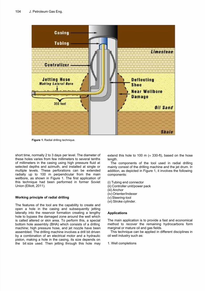
Table 3. Radial drilling operation performed on well 2#.
Depth (ft) 7462 ft 7449 ft
No. of holes 1 2 3 4 5 6
Angle from north 20 150 225 20 150 240
Depth of lateral (ft) 164 164 295 164 164 164
P I ( b p d /
p s i )
Time (min)
B H P
s i
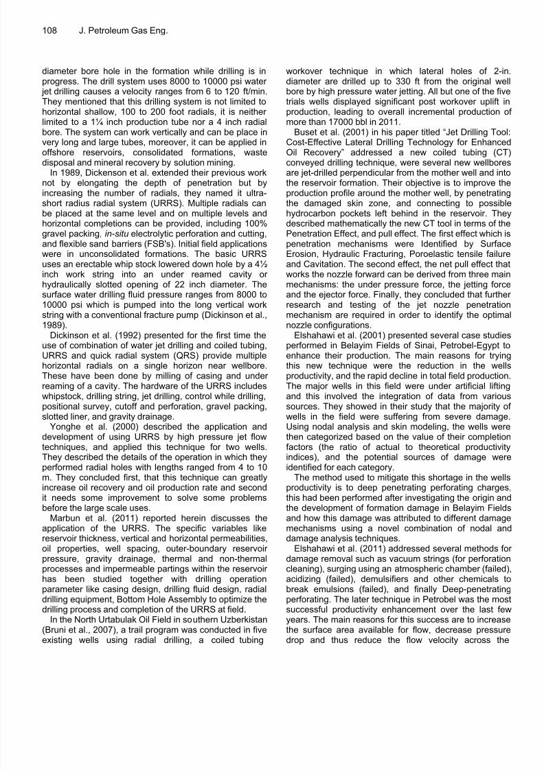
Figure 14. B.H.P and P.I vs. time, vacuum test results before radial drilling.
Time (min)
P I ( b p d / p s i )
B H P
( p s i )
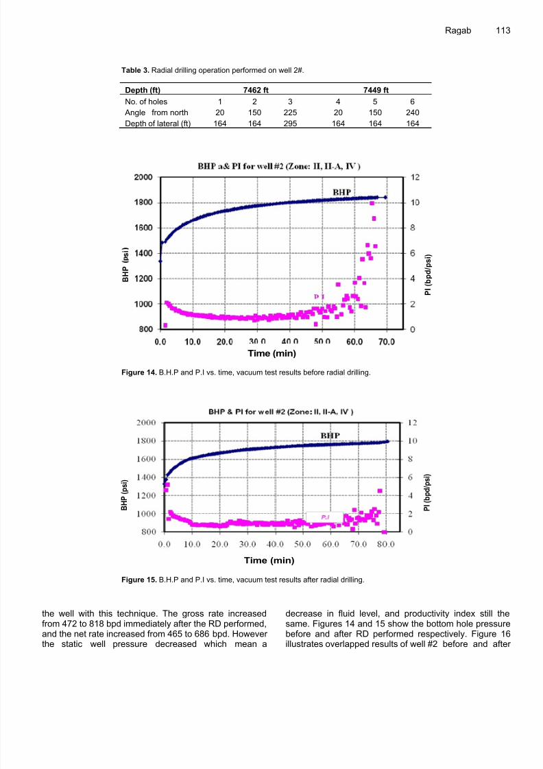
Figure 15. B.H.P and P.I vs. time, vacuum test results after radial drilling.
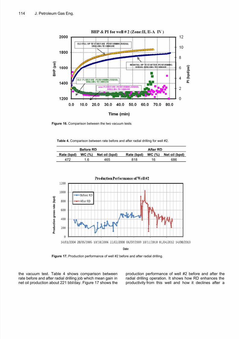
the well with this technique. The gross rate increasedfrom 472 to 818 bpd immediately after the RD performed,and the net rate increased from 465 to 686 bpd. Howeverthe static well pressure decreased which mean a
decrease in fluid level, and productivity index still thesame. Figures 14 and 15 show the bottom hole pressurebefore and after RD performed respectively. Figure 16illustrates overlapped results of well #2 before and afte
8/12/2019 Article1379947252_ragab Radial Drilling
http://slidepdf.com/reader/full/article1379947252ragab-radial-drilling 12/15
114 J. Petroleum Gas Eng.
P I ( b p d / p s i )
Time (min)
B H P
( p s i )
Figure 16. Comparison between the two vacuum tests.
Table 4. Comparison between rate before and after radial drilling for well #2.
Before RD After RD
Rate (bpd) WC (%) Net oil (bpd) Rate (bpd) WC (%) Net oil (bpd)
472 1.6 465 818 16 686
P r o d u c t i o n
g r o s s r a t e ( b p d )
Figure 17. Production performance of well #2 before and after radial drilling.
the vacuum test. Table 4 shows comparison betweenrate before and after radial drilling job which mean gain innet oil production about 221 bbl/day. Figure 17 shows the
production performance of well #2 before and after theradial drilling operation. It shows how RD enhances theproductivity from this well and how it declines after a

8/12/2019 Article1379947252_ragab Radial Drilling
http://slidepdf.com/reader/full/article1379947252ragab-radial-drilling 13/15
Ragab 115
Figure 18. Casing and perforation sketch for well #3.
Table 5. Radial drilling operation performed on well #3.
Depth (ft) 8088 ft 8059 ft
No. of holes 1 2 3 4
Angle from the north 115 295 115 295
Depth of lateral (ft) 164 164 164 164
short period of time.
Case 3: Well #3
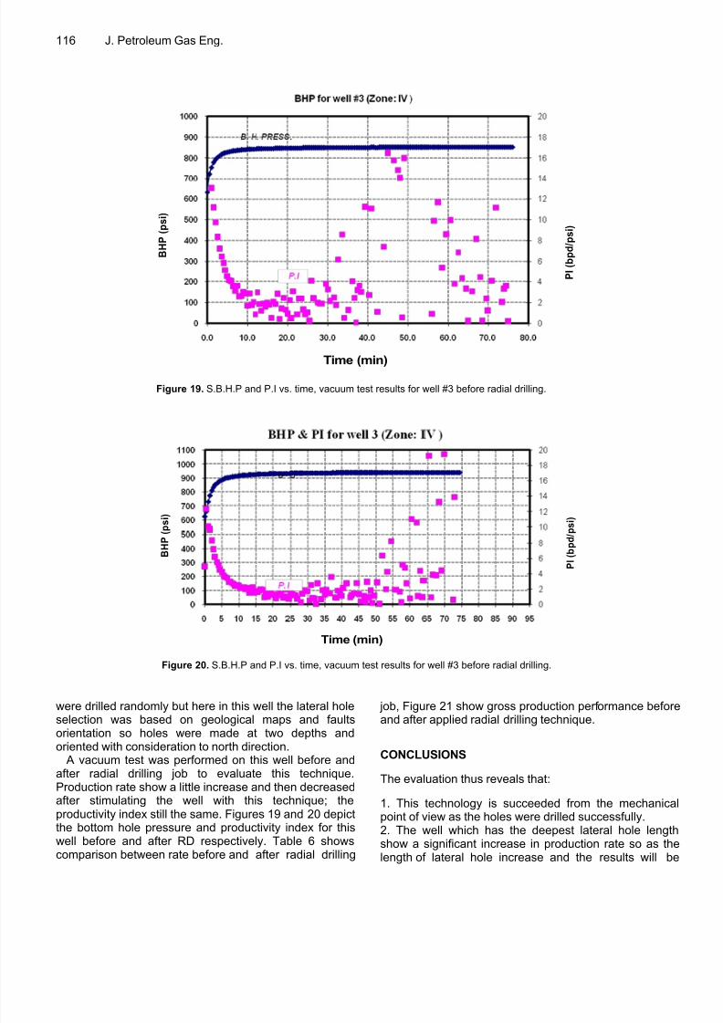
This well is produced from only one zone (zone IV) withaverage daily rate 189 bpd, the static reservoir pressureis about 970 psi at datum 7900 feet sub sea level andproductivity index is 2 barrel per day per psi from lastvacuum test before applied radial drilling, the averageporosity 20%, heterogeneous permeability, the total
depth of this well is about 8994 ft, and net pay thicknessis 87 ft. Figure 18 illustrates casing specification andperforation interval of well #3.
Radial drilling job was performed on this well by millingand jetting four lateral holes at two depths with 164 flateral length from zone IV. There were a lot of trials tomake another two holes at another depth but the holeswere canceled due to 1¾” bit and flexible shaft lost inhole several time, and that cause more lost time. Table 5shows the depths and the length of penetration of eachdrain holes. In the first well, well #1 the lateral holes
8/12/2019 Article1379947252_ragab Radial Drilling
http://slidepdf.com/reader/full/article1379947252ragab-radial-drilling 14/15
116 J. Petroleum Gas Eng.
Time (min)
P I ( b p d / p s i )
B H P
( p s i )
Figure 19. S.B.H.P and P.I vs. time, vacuum test results for well #3 before radial drilling.
B H P
( p s i )
P I ( b p d / p s i )
Time (min)
Figure 20. S.B.H.P and P.I vs. time, vacuum test results for well #3 before radial drilling.
were drilled randomly but here in this well the lateral hole
selection was based on geological maps and faultsorientation so holes were made at two depths andoriented with consideration to north direction.
A vacuum test was performed on this well before andafter radial drilling job to evaluate this technique.Production rate show a little increase and then decreasedafter stimulating the well with this technique; theproductivity index still the same. Figures 19 and 20 depictthe bottom hole pressure and productivity index for thiswell before and after RD respectively. Table 6 showscomparison between rate before and after radial drilling
job, Figure 21 show gross production performance before
and after applied radial drilling technique.
CONCLUSIONS
The evaluation thus reveals that:
1. This technology is succeeded from the mechanicapoint of view as the holes were drilled successfully.2. The well which has the deepest lateral hole lengthshow a significant increase in production rate so as thelength of lateral hole increase and the results will be

8/12/2019 Article1379947252_ragab Radial Drilling
http://slidepdf.com/reader/full/article1379947252ragab-radial-drilling 15/15
Ragab 117
Table 6. Comparison between rate before and after radial drilling for well #3.
Before radial drilling After radial drilling
Rate (bpd) WC (%) Net oil (bpd) Rate (bpd) WC (%) Net oil (bpd)
220 3.2 214 252 3.2 245
G r o s s r a t e ( b p d )
Figure 21. Production performance of well 3 # before and after radial drilling.
more good.3. Using this technique in consolidated rock better thanun-consolidated ones in order to maintain the hole open.4. The technology has been successfully applied toprovide multiple horizontal radials at the same level in asingle well.
5. Radial drilling by high-pressure jet flow techniques cangreatly increase oil recovery and oil production rate.6. Before the large scale usage of this technique, rockmechanics must be considered prior to design.7. Increase in the reservoir contact length (improve drainefficiency), therefore increase the production, control thedirection of perforations, and can be low cost whenutilized in existing wells.8. Further research and testing of the jet nozzlepenetration mechanism are required in order to identifythe optimal nozzle configurations.9. Easy to be applied and less expensive than otherconventional techniques.10. The experience shows that it is necessary to havepetrophysical studies, rock mechanics and pressuretests, prior to intervention, to know the reservoirconditions.11. An improvement is needed in order to maintain therate increase in production rate, such as gravel packingor using slim tubes specially in unconsolidated formation.
REFERENCES
Abdel-Ghany MA, Siso S, Hassan AM, Pierpaolo P, Roberto C (2011).New Technology Application, Radial Drilling Petrobel, First Well in
Egypt, presented at the 10th Offshore Mediterranean Conferenceand Exhibition (OMC) in Ravenna, Italy.
Bruni M, Biassotti H, Salomone G (2007). Radial Drilling in ArgentinaSPE Paper 68504, Latin American and Caribbean PetroleumEngineering Conference, Buenos Aires, Argentina.
Buset P, Riiber M, Arne E (2001). Jet Drilling Tool: Cost-EffectiveLateral Drilling Technology for Enhanced Oil Recovery. Presented athe SPE/ICoTA Coiled Tubing Roundtable held in Houston, Texas.
Dickinson W, Dickinson R, Herrera A, Dykstra H, Nees J (1992). SlimHole Multiple Radials Drilled with Coiled Tubing. SPE 23639presented at the Second Latin American Petroleum EngineeringConference held in Caracas, Venezuela.
Dickinson W, Anderson RR, Dickinson RW (1989). The Ultrashort-Radius Radial System. SPE Paper 14804, SPE Drilling Engineeringpp. 247-254.
Dickinson W, Dickenson RW (1985). Horizontal Radial Drilling SystemSPE 13949, presented at the SPE 1985 California Regional Meetingheld in California.
Elliott S (2011). Coiled-tubing Method Drills radial Laterals to ImproveOil Production from a Depleted Reservoir. World Oil 232:10.
Elshahawi H, Siso S, Samir M, Safwat M (2001). ProductionEnhancement in the Belayim Fields: Case Histories. SPE 68688presented at the SPE Asia Pacific Oil and Gas Conference andExhibition held in Jakarta, Indonesia.
Marbun BTH, Sinaga SZ, Arliyando L, Putra SK (2012). Review oUltrashort-Radius Radial System (URRS). IPTC 14823, presented athe International Petroleum Technology Conference held in BangkokThailand.
Yonghe L, Chunjie W, Lianhai S, Weiyi G (2000). Application andDevelopment of Drilling and Completion of the Ultrashort-radiusRadial Well by High Pressure Jet Flow Techniques. SPE 64756presented at the SPE International Oil and Gas Conference andExhibition in China held in Beijing, China.