article numerical investigation of the collapse of the
TRANSCRIPT

Article
Numerical Investigation of the Collapse of the Steel
Truss Roof and a Probable Reason of Failure
Mertol Tüfekci 1*, Ekrem Tüfekci 2 and Adnan Dikicioğlu 2,
1 Department of Mechanical Engineering Imperial College London, Exhibition Road, London SW7 2AZ,
UNITED KINGDOM; [email protected] 2 Istanbul Technical University, Faculty of Mechanical Engineering, 34437 Gumussuyu-Istanbul-TURKEY;
[email protected], [email protected]
* Correspondence: [email protected]
Abstract: This study investigates the failure of a roof with steel truss construction of a factory
building in Tekirdag in North-western part of Turkey. The failure occurred under hefty weather
conditions including thunderbolt, lightning strikes, heavy rain and fierce winds. In order to
interpret the reason for the failure, the effects of different combinations of factors on the design and
dimensioning of the roof are checked. Therefore, finite element analysis is performed several times
under different assumptions and considering different factors aiming to determine the dominant
ones that are responsible for the failure using the commercial software Abaqus (Dassault Systèmes,
Vélizy-Villacoublay, France). Each loading condition gives out a characteristic form of failure. The
scenario with the most similar form of failure to the real collapse is considered as the most likely
scenario of failure. Also, the factors included in this scenario are expected to be the responsible
factors for the partial collapse of the steel truss structure.
Keywords: Steel truss; roof structure; partial collapse; finite element analysis; lightning strike.
1. Introduction
Engineers aim to make human life easier and to enhance life quality. Throughout mathematical
calculations and experimentation, engineers try to predict the behaviour of a system and make its
design accordingly [1]. However, there have been cases that ended up in undesirable ways and some
caused financial loss or even costed lives. Hadipriono studied nearly 150 major failures of structures
around the world and denoted that the major failures are due to the lateral impact forces [2].
Moreover, Klasson published a survey covering failures of slender roofs [3]. Even the simplest
structures, which have the most predictable behaviours, fail under unexpected conditions that exceed
the designated safety margins [4,5].
Trusses are one of the most widely used and easy-to-design light structures [6]. They are able to
carry very large loads relative to their own weights in very large spans. This is one of the main reasons
that truss type of structures are preferred to build roof and bridge structures. The possible loads are
standardised to help engineers design the structure in a very simple and straightforward way [7].
The standardised loads can be multiple times greater than the structures’ own weight. In the case of
unexpectedly excessive loads of accumulated snow or rainwater, failure of the designed structure
may be unavoidable [8,9]. Geis et al. studied more than 1000 snow-induced building failure incidents
in all over the world [10]. An accumulated mass may cause failure in various ways. Excessive weight
loads acting on the structures lead to a different load distribution than the designed distribution due
to some members entering the plastic region and/or buckling [11–13].
Also, the loads caused by dynamical effects such as earthquakes could lead to failure [14–16].
Structures are more vulnerable to dynamic loads than static loads [17–19]. A way to improve the
performance of structures against the dynamic loads is to add damping to the structure [20].
Earthquakes are not the only sources that cause dynamic loads on structures. One of the main
dynamic effects, that may lead to sudden or progressive collapses, is wind [21–24]. The wind is a very
Preprints (www.preprints.org) | NOT PEER-REVIEWED | Posted: 26 October 2020 doi:10.20944/preprints202010.0151.v2
© 2020 by the author(s). Distributed under a Creative Commons CC BY license.

significant factor that leads to lateral loads to which building structures are relatively more sensitive
compared to vertical loads [25]
A crucial dynamic effect is a very complicated phenomenon, lightning strike [26]. A lightning
strike can cause partial damage or complete failure of structures [27,28]. Specifically, there are cases
where the main reason reported for structural failure is lightning strike [29–32]. In Australia, it is
reported that the lightning strike is found as the reason for damage for 21% of insurance claims for
damaged buildings [33]. A lightning strike can affect a structure in many different ways. However,
two of them are the most dangerous ones, namely, blast (local and rapid pressure oscillations) and
heating [34]. Previous research proved the heating effects of the lightning strike phenomenon [35,36].
It is known that a lightning strike increases the temperature rapidly in a very short period of time
[29,37]. The electric current that is caused by the lighting strike heats up the structure so that it can
start fires [38]. Besides, fire alone can also be the main factor that leads to structural failure [39–42].
Lightning is also one of the key points of this study. Of course, the structures are not affected
just by one of these consequences of the lightning strike phenomenon. Instead, the combination of
these enumerated parameters creates a synergy effect, which increases the resultant influence of the
factors so that it becomes greater than a superposition of these contributing load components [43].
The effects of the lightning strike can be even more dramatic on the structures when there is
cumulated water on top of the structure since the local blasts amplified by the presence of the water
and thermal changes influence the structure all together [34,44].
There are different types of failure mechanisms as well as different types of reasons for the
collapse. Thus, it is possible to find possible reasons for the failure just from the mode/form of the
failure. One of the most important types of failure mechanisms is fatigue [45]. Fatigue may lead to
the progressive collapse of the structures [46,47]. Progressive collapse may happen instantly
following the changed load distribution of members due to buckling and/or failure of some members
[48,49]. But it does not have to happen as the time the initiation of failure of individual members but
happens after the failure of a certain number of members failing successively [50,51].
There are experimental research focusing on the mechanical behaviour of some specific
components and/or structures that are used in trusses [15,52–55]. In the past studies by various
researchers real roof structures put through experimental testing in order to obtain mechanical
behaviour [15,56,57]. As it is obvious, not in every case experimentation is possible and/or feasible.
Therefore, numerical studies are conducted to predict the mechanical behaviour as well as predicting
a plausible failure. For truss type of structures, finite element method is usually employed for trusses
since it is one of the most powerful tools of engineering [14,22,57,58]. Pieraccini et al. studied the
collapse of a spatial truss roof of a gym building in North Italy during a moderate snowfall by using
finite element method [59]. They reported that the elements and connections made by ductile or
brittle materials influenced the bearing capacity of the roof structures as well as the geometric
imperfections.
On the other hand, not all the failures occur over the progress that takes time. As mentioned
earlier, some collapses occur suddenly under excessive impulsive loadings. This study aims to handle
a case, which a sudden partial failure of a steel truss roof of a factory built in July 2011, happened
under heavy weather conditions on 22.10.2012 in Cerkezkoy Tekirdag in Northwestern part of
Turkey [8]. The main focus is on developing a plausible theory for the failure by employing numerical
analyses performed using the finite element method, which covers various loading conditions and
their combinations. Not only the truss roof but also the truss roof with the column supports are
analysed. Thus, the results of numerical analyses are used to compare obtained failure modes to real
failure considering different criteria for failure. The extreme loads due to the ponding of rainfall or
snow accumulation and the temperature shock due to the thunderstorm are considered in the
analyses. Even under these potential mechanical overloads, no damage is observed. It is observed
that the damage caused by these excessive loads occurred in different regions than the current
damage. While the studies in the literature mostly describe failures due to vertical loads caused by
water/snow accumulation or winds as horizontal loads, this study shows that the critical regions
created by the temperature change are similar to the currently damaged zones.
Preprints (www.preprints.org) | NOT PEER-REVIEWED | Posted: 26 October 2020 doi:10.20944/preprints202010.0151.v2

2. Theory and Case Study
2. Materials and Methods
2.1. Overview of the Structure and the Case
The building consists of six partitions with different sizes and an administration building. The
design and all the relevant details of the structure are provided by the company, which undertook
the design and the construction of the building. The steel truss roof structure, which is supported on
the steel-reinforced concrete columns, covers a total area of 30180 m2.
The slope of the roof is 1 % in each direction. The parapets of 15 and 25 cm heights surround the
roof which is equipped with the siphonic drainage system. The layout, as well as the damaged parts,
which are marked with white colour, of the structure, are presented schematically in Figure 1. As it
is shown, the entire structure is made of seven partitions including an administrative office and six
halls where the industrial manufacturing took place.
Figure 1. Layout and damaged regions of the roof structure.
The main dimensions of the unit truss system are presented in Figure 2. The steel carrier system
consists of a double-layer truss with a depth of 2m. The bars of this system have circular tube cross-
sections with different wall thicknesses and diameters depending on their predicted loads. At both
ends of the bars, screw threads are located to enable connecting those members to the mero system.
Mero system includes steel spherical parts which have screw holes. It is noted that no eccentricity at
nodes is observed after the assembly of the individual members. The blocks are divided from each
other with expansion joints.
Preprints (www.preprints.org) | NOT PEER-REVIEWED | Posted: 26 October 2020 doi:10.20944/preprints202010.0151.v2
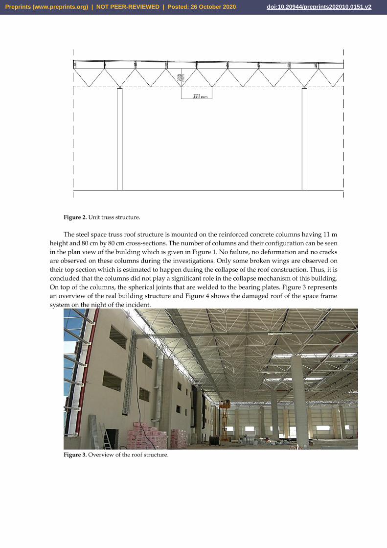
Figure 2. Unit truss structure.
The steel space truss roof structure is mounted on the reinforced concrete columns having 11 m
height and 80 cm by 80 cm cross-sections. The number of columns and their configuration can be seen
in the plan view of the building which is given in Figure 1. No failure, no deformation and no cracks
are observed on these columns during the investigations. Only some broken wings are observed on
their top section which is estimated to happen during the collapse of the roof construction. Thus, it is
concluded that the columns did not play a significant role in the collapse mechanism of this building.
On top of the columns, the spherical joints that are welded to the bearing plates. Figure 3 represents
an overview of the real building structure and Figure 4 shows the damaged roof of the space frame
system on the night of the incident.
Figure 3. Overview of the roof structure.
Preprints (www.preprints.org) | NOT PEER-REVIEWED | Posted: 26 October 2020 doi:10.20944/preprints202010.0151.v2

Figure 4. Damage on the roof of the space truss system.
On the day of the incident, more than 500 lightning activities are detected in the region by the
British Meteorological Office’s (The Met Office) ATDnet (Arrival Time Difference Network) system
and the Vaisala Global Lightning Dataset GLD360. It is determined that lightning struck the building
and the lightning rods worked. Meteorological data indicate that thunderstorms are rainy and the
wind blows from 40 to 60 km/h from the north and northeast directions and up to 70 to 80 km/h
locally. The rainfall is 22.6 mm during the collapse, although much heavy local rainfalls occurred
several times in recent years. Around the roof, there are several siphonic at 5 cm height. The heights
of the parapets on the roof is 15 cm and 25 cm. Although no scupper is required to be used such
shallow parapets, there are several scuppers of 15 cm height on the roof structure.
2.2. Structural Members
The members having steel tube sections with different diameters and thicknesses are used in the
truss roof system. The pipe elements with screwed cone ends are connected to the hot forged steel
spherical joints. These joints ensured that no eccentricity occurred and the only axial forces are
developed in the bars of the truss system. The yield strength of the material (S235JR) of bars and the
cone parts at the ends of them (DIN 2458) is 235 MPa, ultimate tensile strength is 510 MPa and the
allowable stress can be chosen as 144 MPa. The bolts used for mounting the bars to the spherical joints
are made of 10.9 material quality. The tensile strength of the bolts is 1000 MPa yield strength 900 MPa
and the allowable strength is 360 MPa in which the safety factor is 2.5. The spherical joints used to
connect the rods to each other and the supports are made of hot forged steel with the yield stress of
330 MPa and the tensile strength of 590 MPa. The strength values and the chemical decompositions
of the materials used in the truss roof system are validated by Piroglu et al [8].
The support spheres are fixed onto the concrete columns by using square or circular plates bolted
to the columns. The supports are made of EN C45 steel and Teflon plates are placed under the sliding
ones to reduce friction. The details of the joints and supports are given in Figure 5.
Preprints (www.preprints.org) | NOT PEER-REVIEWED | Posted: 26 October 2020 doi:10.20944/preprints202010.0151.v2

Figure 5. View of the spherical joints and the supports
3.Analysis
Two main groups of analyses are performed within the scope of this study. The first group is
called the global analysis where the whole load-carrying members of the building are considered as
beams and bars while the second group of analysis considers the individual columns and supports.
The first group includes multiple case scenarios with different combinations of loads. Only two
major cases are presented in this study for the sake of simplicity.
The second group consists of two stages as well. The first stage investigates the effective material
properties of the concrete column reinforced with steel rods under uniaxial tensile strain conditions.
Thus, the column is handled as a composite material. The second stage investigates the individual
column support connection under the highest forces determined by the global model acting on an
individual support.
All the simulations are conducted using the commercial software Abaqus (Dassault Systèmes,
Vélizy-Villacoublay, France) under static loading assumptions.
The three most important material properties, namely Young’s modulus (E), Poisson’s ratio (ν)
and the thermal expansion coefficient (α) are taken as shown in Table 1.
Table 1. The material properties considered in the analyses.
Property Steel Concrete
Young’s modulus (E) 210 GPa 32 GPa
Poisson’s ratio (ν) 0.28 0.20
Thermal expansion
coefficient (α)
13 μm/(m K) 11.5 μm/(m K)
3.1. Global Analysis
The given design of the structure is recreated in a compatible CAD format and it is imported
into a commercial finite element software which is mentioned above. The finite element model is
used to simulate some assumptions and certain loading conditions with a consideration of geometric
nonlinearities. The boundary conditions are defined as appropriate to the actual structure and the
loads applied to the truss roof system are defined as given in Table 2 which are greater than the loads
that are assumed for the design. So, the main purpose of this global analysis is to get a better
understanding of the mechanical behaviour and to predict the failure modes under different loads
and assumptions. It is worthy to note that all the analyses are run in a static manner. Since the
equivalent static loads are determined using the relevant Turkish standards, it is appropriate to use
this simplification [8].
One of the most important aspects here is that the presented strength and elastic properties of
the materials and members used are put through tests and experimental processes and they have
found to be consistent in general with the standards [8]. So, in the analyses performed for this study,
the values which are presented in the reports of the company will be mainly used.
Preprints (www.preprints.org) | NOT PEER-REVIEWED | Posted: 26 October 2020 doi:10.20944/preprints202010.0151.v2

Table 2. The loads considered in the analyses.
Load description Value
Own weight of the space truss system 140 N/m2
Dead loads 350 N/ m2
(240 N/m2 given in design calculations)
Snow load 2000 N/m2
(1000 N/m2 given in design calculations.)
Vertical wind loads 960 N/m2
Equivalent earthquake vertical load 950 N/m2
Equivalent earthquake horizontal load 200 N/m2
(180 N/m2 given in design calculations)
Different dead, live, snow, temperature and earthquake loads are considered in the design
consideration. Rain load caused by an excessive accumulation of water especially on low-slope or flat
roofs where the parapets mounted around the roof can dramatically cause partial or total destruction
if they are not considered in the design. But, the rainfall ponding on the roof is considered in the
design. The design code used gives the wind loads for the buildings of 20-90 m tall as 0.8 kN/m2
(pressure) on the windward and -0.4 kN/m2 (suction) on the leeward side. For the seismic loads, the
earthquake acceleration is taken as 0.3g, where g is the gravitational acceleration, so the earthquake
loads are overestimated [8].
The loads acting on the space truss system are to be transmitted to the bars over the spherical
steel elements called nodes. The weight of the space truss roof system is taken as 140 N/m2, the dead
load from coatings and the installation is given in the design documents as 240 N/m2 but it is assumed
as 350 N/m2 in the analysis. The snow load is given in the design calculations as 1000 N/m2 and it is
taken as 2000 N/m2 in the analysis. The equivalent earthquake horizontal load is given as 180 N/m2
in the design calculations and it is considered here as 200 N/m2. Equivalent earthquake vertical load
is 950 N/m2 and the vertical wind load is 960 N/m2. Table 2 gives the loads used in the analyses.
The boundary conditions of the space truss system and the columns are arranged as the original
design of the structure.
Figure 6. Three-dimensional finite element model prepared for FE analysis.
The bars of the space truss are modelled based on the standards of DIN S235 JR quality linear
elastic materials and columns are modelled as C35 grade homogeneous and linear elastic steel-
Preprints (www.preprints.org) | NOT PEER-REVIEWED | Posted: 26 October 2020 doi:10.20944/preprints202010.0151.v2

reinforced concrete with the elasticity modulus which is determined using the homogenisation of the
composite column analysis. The bar elements in the space truss system and the beam elements in the
columns are assembled as the whole system of 160133 elements and 461847 nodes. Figure 6 displays
the model for global analysis in a commercial finite element software. With this model, a static global
analysis of the space truss system is performed with the above-mentioned loads being quite larger
than the design loads.
3.2. Analysis of the Columns and Supports
This section covers the analysis performed to gain more insights into the mechanical behaviour
of the columns and the supports which either are not very accurately represented in the global model
or to increase the accuracy of the global model. The first stage of this group of analysis aims to
homogenise the composite column and the second stage investigates the mechanical behaviour of
column and support behaviour focusing on the stress/strength of the structure.
3.2.1. Analysis of the Steel-Reinforced Columns
The main purpose of this analysis is to understand the effective material properties of the steel-
reinforced concrete columns by using three-dimensional finite elements. Here, the column is assumed
to be a composite beam and its material properties are calculated with homogenisation. Thus, it is
aimed to obtain a more realistic global model. For this purpose, a model is created considering the
steel reinforcement of the concrete columns. In this model, the column material is considered as a
composite material with concrete and reinforcing steel rods. The steel rods are placed in the concrete
as shown in Figure 7. The rods and the concrete are rigidly bonded to each other. According to the
general theory of mechanics of composite materials, lateral reinforcement steel binders, which are
predicted to have no significant effect on axial stiffness, are not included in the analysis for the sake
of simplicity. The steel reinforcing rods are taken as given in the project and as described in the
previous section.
Figure 7. CAD of a column with steel-reinforced concrete.
To represent the behaviour, a cross-sectional face is subjected to axial displacement restrictions
whereas the opposite face, which is the other cross-sectional face, is subjected to a uniform axial
displacement. Using the results of the analysis the effective Poisson’s ratio and Young’s modulus are
determined. A similar procedure is also performed for the effective thermal expansion coefficient.
The results of this analysis are used in the global analysis.
Preprints (www.preprints.org) | NOT PEER-REVIEWED | Posted: 26 October 2020 doi:10.20944/preprints202010.0151.v2

3.2.2. Analysis of the Spherical Support with Steel-Reinforced Columns
This part of the study is interested in mechanical behaviour and safety of the column and
spherical support structures. This study uses the highest mechanical loads acting on a single truss-
column connection node calculated in the global analysis. It is also important to note that this analysis
considers only the mechanical loads and does not consider any thermal effects. The analysis of the
column support connection is performed with a three-dimensional finite element model.
The column support connection is built such that the sphere is mounted on the support plate
which is embedded in the steel-reinforced concrete with a bolt connection. The structure of this model
is given in Figure 8.
The contact interfaces between the steel rods and concrete are rigidly bonded as well as the
contact surfaces between the spherical support and the steel plate. The bolts are attached to the model
with a standard preload and connected to the steel plate and concrete with friction.
The bottom cross-sectional face is connected to a grounded spring with 6 degrees of freedom
and with the stiffness values of the rest of the column, to save computational time.
Figure 8. CAD of column support connection with steel-reinforced concrete.
4. Results and Discussion
In this section, the results of the analysis are presented and discussed. Based on the
interpretations of the results that match the actual failure form of the structure, a scenario, which is
judged the most plausible, is described and discussed.
4.1. Analysis of the Steel-Reinforced Columns
The homogenisation study is conducted and the results are presented here. Figure 9 shows the
equivalent stress distribution in the case of axial loading of the composite structure and Figure 10
shows displacement distribution. As a result of this analysis, the elasticity modulus and the resultant
thermal expansion coefficient of the steel-reinforced concrete are calculated as 48 GPa and 12.8 μm/(m
K). This axial elasticity modulus value is used as 50 GPa in global analysis.
Preprints (www.preprints.org) | NOT PEER-REVIEWED | Posted: 26 October 2020 doi:10.20944/preprints202010.0151.v2

Figure 9. Stress distribution in case of axial stress of steel-reinforced concrete column.
Figure 10. Displacement distribution of steel-reinforced concrete column in case of axial stress.
4.2. Global Analysis with only Mechanical Loads
The displacements and the stresses occurring in the truss roof system are calculated by using the
finite element analysis software. Figure 11 shows the vertical displacement (in meters) under the
considered loads. The largest displacements being around 4.7 cm occur in the blocks A, C and E
where the gap between the columns is the largest (28 m), as it is expected. It should be noted here
that due to the positive direction of the axis, which is upwards, blue colours are around zero and red
is the largest in terms of absolute values. The region of the larger resultant displacements is not where
the real damage happened. The deformations of the column structures are so small that they do not
point out any safety issues. The analyses demonstrate clearly that the system is safe and that the
results are consistent with the results obtained by the engineering bureau.
Preprints (www.preprints.org) | NOT PEER-REVIEWED | Posted: 26 October 2020 doi:10.20944/preprints202010.0151.v2

Figure 11. Vertical displacement of the steel-reinforced concrete column system.
Considering the stress analysis, the equivalent stresses by using von Mises criteria are calculated
for all the structure. Figure 12 gives the von Mises stresses in the roof structure (in Pa). It is seen that
all stresses of the roof structure together with the columns are within the safety limits. The collapsed
regions are also within the safety limits. As well as the displacements, the stresses occurring in the
column structures are well below the safety limits. Although exaggerated loads are applied on the
roof structure, the stresses and displacements in the beams and rods show that the structure would
not fail under these combinations of excessive loads.
Figure 12. Equivalent von Mises stress distribution of steel-reinforced concrete column
The greatest stresses occur at these “U” shaped connections shown in Figure 13. Whereas the
displacements are not excessive. It is important to note that, this connection structure does not exist
in the real application. These connections are used in the CAD/FE model in order not to distort the
dimensions of the truss structure. In reality, there are walls with certain thickness whereas the FE
model uses beam elements. To connect the trusses with the supports, such a “dummy” structure is
used. Therefore, the stress values that are read at these connections are disregarded.
Preprints (www.preprints.org) | NOT PEER-REVIEWED | Posted: 26 October 2020 doi:10.20944/preprints202010.0151.v2

Figure 13. Connections with the supports and steel truss at the block interfaces
4.3. Analysis of the Spherical Support with Steel-Reinforced Columns
After finding out that the global structure is safe, the next step is to analyse an individual column
support by using the finite element method. The results of the global analysis are used to determine
the support reactions. At the most dangerous column support connection, the horizontal force is 95
kN and vertical force is 940 kN. The forces are taken as 120 kN in horizontal and 1000 kN in vertical
directions.
Figure 14. Equivalent stress distribution of column support connection.
The equivalent stress distribution obtained in this case is shown in Figure 14. As it can be clearly
seen from this figure, the stress levels are below the yield stress even though extreme loads are
applied. Figure 15 shows a post-damage image of one of the columns to which the space frame roof
system is attached.
Preprints (www.preprints.org) | NOT PEER-REVIEWED | Posted: 26 October 2020 doi:10.20944/preprints202010.0151.v2

Figure 15. Damage on the support to which the space truss roof system is attached.
Figure 16 shows the distribution of the resultant displacement that occurs in the column support
connection. Here, it can be seen that the maximum value of the displacement compounds of the
spherical support is around 0.3 mm.
Figure 16. Resultant displacement distribution of column support connection.
4.4. Global Analysis with Mechanical Loads and Thermal Effects
With these results obtained from the global analysis it is found that increasing horizontal forces
may cause damage, various damage scenarios are investigated by changing the loads applied to the
space frame system. As the first case, the vertical load is increased considerably and no damage is
predicted in the real damaged zones A and F, as given in Figure 1. As the next case, the structure is
tested by increasing the horizontal load. Although the horizontal load value has been increased to a
level that cannot be reached by wind and similar factors, the damage occurred cannot be explained
with these combinations of loads. However, the structure is found more “sensitive and vulnerable”
to the horizontal loads. Finally, it is understood that the space frame system with the columns is safe
against vertical loads (snow, water, etc.) and horizontal loads (wind etc.).
It is obvious that different factors must be present in order to explain the real damage in the
structure. Therefore, considering the natural events occurring on the night of the event, their effects
Preprints (www.preprints.org) | NOT PEER-REVIEWED | Posted: 26 October 2020 doi:10.20944/preprints202010.0151.v2

on the structure are considered. It is interpreted that reasons such as heavy rain that leads to ponding
on the roof with a slope of 1% and plausibly clogged water discharging drainage system would not
cause any damage similar to this one. Besides, around the rooftop surface, there are several scuppers
with 15 cm height. Even with the assumption of full ponding of the roof with 15 cm height, it can be
confidently claimed that the chosen loads for the analysis is on the cautious side and lead to
conservative results which do not point out any damage predictions like the real damage.
On the other hand, a large number of lightning strikes are detected on the night of the incident.
The effects of lightning depend on the energy of the lightning itself and the energy of lightning, which
is impossible to fully determine, depends on many parameters such as the altitude of the cloud where
the lightning originates. It is well known that this discharged energy heats up a considerable amount
of air surrounding the core of lightning. The temperature rise is so rapid and significant that it can
start fires in near the location where lightning strikes [37]. Furthermore, when lightning strikes a
building the electric current passes through the structure which leads to a sudden heat generation
and a rapid increase of temperature [29,37,38]. Besides, quite large shock forces occur due to the
interaction of a large mass of hot and cold air around it, and also due to the humidity of the air and
the ground, which is called the blast effect. Also, it is known that the presence of water amplifies the
blast effect and interacts with the structure under electric current [34]. Therefore, it is thought that
these great shock forces can cause instant damage.
Even though it is judged that the structure is heated, it is impossible to predict or evaluate the
exact or even approximate rise of temperature. For the purpose of understanding the underlying
factors that lead to the damage shown in Figure 1, the effects of temperature change on the structure
are investigated using a simplified approach. The space frame system is given a temperature increase
of 50 °C. The lightning is most likely to cause a local thermal shock and not heating up the entire
structure. However, it is impossible to know the number of lightning strikes, the generated heat, the
temperature rise, generated blast etc.
Based on these assumptions, a 50 °C temperature increase is applied to the global model
alongside the external loads as described in the previous global analysis. A new static model is built
and the results are given in Figures 17-21. Figure 17 shows the equivalent stresses of von Mises
occurring in space truss systems and columns. It is seen that the stresses coming out of this figure are
quite safe. However, it has been found that the stress values in the support joints reach values
exceeding the safety limits and the supports reaching these values are concentrated especially in the
areas where damage occurs. The reason for the great stress values in this global model is that the
model is simple and gives a general idea. It would be appropriate to consider separately the situations
in the supports with large stresses.
Figure 17. Stresses due to load and thermal effects in space frame and steel-reinforced concrete column
system.
Preprints (www.preprints.org) | NOT PEER-REVIEWED | Posted: 26 October 2020 doi:10.20944/preprints202010.0151.v2

It is also to be noted that the “U” shaped connections between the steel truss structures and the
supports on the walls display the greatest stresses which are not realistic, as these connections do not
exist in the real structures. Therefore, those stress values are disregarded.
Figure 18. Resultant displacements due to load and thermal effects in space frame and steel-reinforced
concrete column system.
Figure 18 shows the resultant displacements that occur throughout the system. From this figure,
it can be seen that displacements are suitable and larger displacements occur in the regions where
the damage occurs.
Figure 19. Displacements in the long edge direction caused by load and thermal effects in the space frame
and steel-reinforced concrete column system.
Furthermore, Figure 19 shows the displacements in the long edge direction, say x-direction. This
figure clearly shows that there are large displacements in the areas where the damage occurs. Figure
20 displays the displacements in the direction of the short edge of the building, so-called y-direction.
It is to be noted that the larger displacements are observed in the direction along the shorter edge
whereas the larger displacements due to thermal expansion are expected in the direction of the long
edge. The reason behind it can be explained with different stiffness levels of the structure in different
directions and boundary conditions of the supports. As it can be seen from Figure 6, the number of
columns in the first two rows of the halls B, D, F are much more intensively positioned than the rest
of the building. Moreover, the intensity of the columns in the x-direction is greater than the intensity
Preprints (www.preprints.org) | NOT PEER-REVIEWED | Posted: 26 October 2020 doi:10.20944/preprints202010.0151.v2

of columns in the y-direction. Therefore, the stiffness in the x-direction is expected to be greater than
the stiffness in the y-direction. The sliding supports and the stiffness of the structure allow the
structure to deform in the y-direction more than x-direction, even though the tendency to deform is
more in x-direction than y-direction. This leads to the storage of a larger amount of energy in the x-
direction. Additionally, since, there is no damage in the spherical supports themselves, as can be seen
in Figure 15, the excessive displacements cause larger stress values in the bolt connections between
the spherical parts and the members. Therefore, it is found plausible that this mechanism caused the
actual failure.
Figure 20. Displacements in the short edge direction caused by load and thermal effects in the space frame
and steel-reinforced concrete column system.
The displacements of the structure in the vertical direction given in Figure 20. Comparing the
vertical displacements of the previous global analysis and this one (Figure 11 and 21), both cases
display very similar distribution trends but the new one exhibits larger displacements. This lies on
the facts that, there is a synergy effect based on the complex loading and the thermal expansion leads
to extra loading as well as elongation in horizontal directions.
Figure 21. Displacements in the vertical direction caused by the loads in the space frame and steel-
reinforced concrete column system.
5. Conclusions
Preprints (www.preprints.org) | NOT PEER-REVIEWED | Posted: 26 October 2020 doi:10.20944/preprints202010.0151.v2

The space truss roof structure, the columns and the spherical steel supports of the factory
building are put through several numerical analyses and their behaviour is evaluated using the
commercial software Abaqus (Dassault Systèmes, Vélizy-Villacoublay, France). These static stress
analyses are performed using the finite element method considering geometric nonlinearities. Based
on the results of these simulations, following conclusions about the real failure of the structure are
drawn:
- According to the global analyses, the structure is quite strong and insensitive against the
vertical dead loads (rain, snow, etc.) even at some higher values which are judged to be
extreme and unrealistic. The most dangerous region of the space frame system in terms of
vertical loads is the corridor with the largest column span in the A, C and E blocks. However,
this region is still safe and the damage occurs somewhere else and not there.
- Using the results of the global analysis, the most critical support connection is individually
investigated and found safe. They are more sensitive to horizontal forces though. However,
in the analysis, all the effects that create lateral forces caused by the wind and similar
homogeneous distributed loads cannot make the structure exceed the safety limits and cause
any damage in the locations where the real damage is.
- It is judged that the thermal expansion of structural members increases the horizontal forces
at the supports and the stresses at the members. The temperature change is assumed to be
caused by lightning strikes. To investigate the effects of the temperature change, a simplified
analysis with uniform temperature rise is conducted which produced results that point out
the critical regions the same as the real damaged zones.
- The significant change of temperature of the air surrounding the lightning channel and the
electric current that passes through the structure may cause heating of the roof system
rapidly and locally. The lightning at the scene may also cause a sudden pressure change
which can be amplified by the presence of water on top of the structural surface. In addition
to the thermal expansion, it is judged possible that the blast effect may have a significant
role in the failure of the structure.
- Testing the idea of temperature change, the damage prediction is found consistent with the
real failure mode. It is concluded that the bolts and the bolted members attached to the
supports in the real damaged regions of the space truss roof system are overloaded and
damaged as it can be seen in Figure 15.
Author Contributions: Conceptualization, E.T. and A.D.; methodology, E.T. and A.D.; software, M.T.;
validation, E.T., A.D. and M.T.; formal analysis, M.T., E.T. and A.D.; investigation, M.T.; resources, A.D.; data
curation, M.T.; writing—original draft preparation, M.T., E.T. and A.D.; writing—review and editing, M.T., E.T.
and A.D.; visualization, M.T.; supervision, E.T. and A.D.; project administration, A.D.; All authors have read
and agreed to the published version of the manuscript.
Conflicts of Interest: The authors declare no conflict of interest.
References
1. Wu, Z.; Rong, J.; Liu, C.; Liu, Z.; Shi, W.; Xin, P.; Li, W. Dynamic analysis of spatial truss structures
including sliding joint based on the geometrically exact beam theory and isogeometric analysis. Appl.
Sci. 2020, 10, doi:10.3390/app10041231.
2. Hadipriono, F.C. Analysis of Events in Recent Structural Failures. J. Struct. Eng. 1985, 111, 1468–1481,
doi:10.1061/(ASCE)0733-9445(1985)111:7(1468).
3. Klasson, A.; Björnsson, I.; Crocetti, R.; Hansson, E.F. Slender Roof Structures - Failure Reviews and a
Qualitative Survey of Experienced Structural Engineers. Structures 2018, 15, 174–183,
doi:10.1016/j.istruc.2018.06.009.
4. Deshpande, V.S.; Fleck, N.A. Collapse of truss core sandwich beams in 3-point bending. Int. J. Solids
Preprints (www.preprints.org) | NOT PEER-REVIEWED | Posted: 26 October 2020 doi:10.20944/preprints202010.0151.v2

Struct. 2001, 38, 6275–6305, doi:10.1016/S0020-7683(01)00103-2.
5. Ballarini, R.; La Mendola, L.; Le, J.L.; Monaco, A. Computational study of failure of hybrid steel trussed
concrete beams. J. Struct. Eng. (United States) 2017, 143, 1–13, doi:10.1061/(ASCE)ST.1943-541X.0001792.
6. Wu, Y.; Xiao, Y. Steel and glubam hybrid space truss. Eng. Struct. 2018, 171, 140–153,
doi:10.1016/j.engstruct.2018.05.086.
7. Sun, W.; Zhang, Q. Universal equivalent static wind loads of fluctuating wind loads on large-span roofs
based on compensation of structural frequencies and modes. Structures 2020, 26, 92–104,
doi:10.1016/j.istruc.2020.04.008.
8. Piroglu, F.; Ozakgul, K.; Iskender, H.; Trabzon, L.; Kahya, C. Site investigation of damages occurred in
a steel space truss roof structure due to ponding. Eng. Fail. Anal. 2014, 36, 301–313,
doi:10.1016/j.engfailanal.2013.10.018.
9. Goto, Y.; Kawanishi, N.; Honda, I. Dynamic stress amplification caused by sudden failure of tension
members in steel truss bridges. J. Struct. Eng. 2011, 137, 850–861, doi:10.1061/(ASCE)ST.1943-
541X.0000338.
10. Geis, J.; Strobel, K.; Liel, A. Snow-Induced Building Failures. J. Perform. Constr. Facil. 2012, 26, 377–388,
doi:10.1061/(ASCE)CF.1943-5509.0000222.
11. Altunişik, A.C.; Ateş, Ş.; Hüsem, M. Lateral buckling failure of steel cantilever roof of a tribune due to
snow loads. Eng. Fail. Anal. 2017, 72, 67–78, doi:10.1016/j.engfailanal.2016.12.010.
12. Thai, H.T.; Kim, S.E. Nonlinear inelastic time-history analysis of truss structures. J. Constr. Steel Res. 2011,
67, 1966–1972, doi:10.1016/j.jcsr.2011.06.015.
13. Shivarudrappa, R.; Nielson, B.G.; Asce, M. Sensitivity of load distribution in light-framed wood roof
systems due to typical modeling parameters. J. Perform. Constr. Facil. 2013, 27, 222–234,
doi:10.1061/(ASCE)CF.1943-5509.0000323.
14. Malla, R.B.; Nalluri, B.B. Dynamic effects of member failure on response of truss-type space structures.
J. Spacecr. Rockets 1995, 32, 545–551, doi:10.2514/3.26649.
15. Parisi, M.A.; Piazza, M. Seismic behavior and retrofitting of joints in traditional timber roof structures.
Soil Dyn. Earthq. Eng. 2002, 22, 1183–1191, doi:10.1016/S0267-7261(02)00146-X.
16. Pollino, M.; Bruneau, M. Seismic testing of a bridge steel truss pier designed for controlled rocking. J.
Struct. Eng. 2010, 136, 1523–1532, doi:10.1061/(ASCE)ST.1943-541X.0000261.
17. Sosorburam, P.; Yamaguchi, E. Seismic retrofit of steel truss bridge using buckling restrained damper.
Appl. Sci. 2019, 9, doi:10.3390/app9142791.
18. Chou, C.C.; Chen, J.H. Seismic tests of post-tensioned self-centering building frames with column and
slab restraints. Front. Archit. Civ. Eng. China 2011, 5, 323–334, doi:10.1007/s11709-011-0119-5.
Preprints (www.preprints.org) | NOT PEER-REVIEWED | Posted: 26 October 2020 doi:10.20944/preprints202010.0151.v2

19. Zhao, H.; Ding, Y.; Nagarajaiah, S.; Li, A. Longitudinal displacement behavior and girder end reliability
of a jointless steel-truss arch railway bridge during operation. Appl. Sci. 2019, 9, doi:10.3390/app9112222.
20. Rezaei, S.; Akbari Hamed, A.; Basim, M.C. Seismic performance evaluation of steel structures equipped
with dissipative columns. J. Build. Eng. 2020, 29, doi:10.1016/j.jobe.2020.101227.
21. Qu, W.L.; Chen, Z.H.; Xu, Y.L. Dynamic Analysis of Wind Excited Truss Tower With Friction Dampers.
Comput. Struct. 2001, 79, 2817–2831.
22. Spyrakos, C.C.; Raftoyiannis, I.G.; Ermopoulos, J.C. Condition assessment and retrofit of a historic steel-
truss railway bridge. J. Constr. Steel Res. 2004, 60, 1213–1225, doi:10.1016/j.jcsr.2003.11.004.
23. Zheng, H.D.; Fan, J. Analysis of the progressive collapse of space truss structures during earthquakes
based on a physical theory hysteretic model. Thin-Walled Struct. 2018, 123, 70–81,
doi:10.1016/j.tws.2017.10.051.
24. Maraveas, C.; Tsavdaridis, K.D. Assessment and retrofitting of an existing steel structure subjected to
wind-induced failure analysis. J. Build. Eng. 2019, 23, 53–67, doi:10.1016/j.jobe.2019.01.005.
25. Foraboschi, P. Lateral load-carrying capacity of steel columns with fixed-roller end supports. J. Build.
Eng. 2019, 26, doi:10.1016/j.jobe.2019.100879.
26. Rakov, V.A. The physics of lightning. Surv. Geophys. 2013, 34, 701–729, doi:10.1007/s10712-013-9230-6.
27. Hartono, Z.A.; Ibrahim, R. A database of lightning damage caused by bypasses of air terminals on
buildings in Kuala Lumpur, Malaysia. In Proceedings of the VI International Symposium on Lightning
Protection; 2001.
28. Bothma, J.G. Transmission line tower collapse investigation: A case study. IEEE Power Energy Soc. Conf.
Expo. Africa Intell. Grid Integr. Renew. Energy Resour. PowerAfrica 2012 2012,
doi:10.1109/PowerAfrica.2012.6498616.
29. Mills, B.; Unrau, D.; Pentelow, L.; Spring, K. Assessment of lightning-related damage and disruption in
Canada. Nat. Hazards 2010, 52, 481–499.
30. Zhang, W.; Meng, Q.; Ma, M.; Zhang, Y. Lightning casualties and damages in China from 1997 to 2009.
Nat. Hazards 2011, 57, 465–476.
31. Krausmann, E.; Renni, E.; Campedel, M.; Cozzani, V. Industrial accidents triggered by earthquakes,
floods and lightning: Lessons learned from a database analysis. Nat. Hazards 2011, 59, 285–300.
32. Patel, K. Effect of Lightning on Building and Its Protection Measures. Int. J. Eng. Adv. Technol. 2013, 182.
33. Blong, R. Residential building damage and natural perils: Australian examples and issues. Build. Res. Inf.
2004, 32, 379–390, doi:10.1080/0961321042000221007.
34. Shivalli, S. Lightning Phenomenon , Effects and Protection of Structures from Lightning Sanketa Shivalli.
IOSR J. Electr. Electron. Eng. 2016, 11, 44–50.
Preprints (www.preprints.org) | NOT PEER-REVIEWED | Posted: 26 October 2020 doi:10.20944/preprints202010.0151.v2

35. Zhivlyuk, Y.; Mandel’shtam, S. On the temperature of lightning and force of thunder. Sov. Phys. JETP
1961, 13, 338–340.
36. Mu, Y.; Yuan, P.; Wang, X.; Dong, C. Temperature distribution and evolution characteristic in lightning
return stroke channel. J. Atmos. Solar-Terrestrial Phys. 2016, 145, 98–105, doi:10.1016/j.jastp.2016.04.013.
37. Elsom, D.M.; Webb, J.D.C. Lightning Impacts in the United Kingdom and Ireland. In Extreme Weather;
2016; pp. 195–207.
38. Holle, R.L.; López, R.E.; Arnold, L.J.; Endres, J. Insured Lightning-Caused Property Damage in Three
Western States. J. Appl. Meteorol. 1996, 35.
39. Kmet, S.; Tomko, M.; Demjan, I.; Pesek, L.; Priganc, S. Analysis of a damaged industrial hall subjected
to the effects of fire. Struct. Eng. Mech. 2016, 58, 757–781, doi:10.12989/sem.2016.58.5.757.
40. Usmani, A.S. Stability of the world trade center twin towers structural frame in multiple floor fires. J.
Eng. Mech. 2005, 131, 654–657, doi:10.1061/(ASCE)0733-9399(2005)131:6(654).
41. Behnam, B. Fire Structural Response of the Plasco Building: A Preliminary Investigation Report. Int. J.
Civ. Eng. 2019, 17, 563–580, doi:10.1007/s40999-018-0332-x.
42. Mwangi, S. Why Broadgate Phase 8 composite floor did not fail under fire : Numerical investigation
using ANSYS® FEA code. J. Struct. Fire Eng. 2017, 8, 238–257, doi:10.1108/JSFE-05-2017-0032.
43. Usmani, A.S.; Chung, Y.C.; Torero, J.L. How did the WTC towers collapse: A new theory. Fire Saf. J. 2003,
38, 501–533, doi:10.1016/S0379-7112(03)00069-9.
44. Meppelink, J. The Impact of a lightning Stroke on a Flat Roof When the Building is Filled with Water.
Light. Prot. (ICLP), 1998 Int. Conf. 1998, 826–831.
45. Li, H.; Wu, G. Fatigue evaluation of steel bridge details integrating multi-scale dynamic analysis of
coupled train-track-bridge system and fracture mechanics. Appl. Sci. 2020, 10, doi:10.3390/app10093261.
46. Blandford, G.E. Progressive failure analysis of inelastic space truss structures. Comput. Struct. 1996, 58,
981–990, doi:10.1016/0045-7949(95)00217-5.
47. Blandford, G.E. Review of Progressive Failure Analyses for Truss Structures. J. Struct. Eng. 1997, 123,
122–129, doi:10.1061/(ASCE)0733-9445(1997)123:2(122).
48. Malla, R.B.; Agarwal, P.; Ahmad, R. Dynamic analysis methodology for progressive failure of truss
structures considering inelastic postbuckling cyclic member behavior. Eng. Struct. 2011, 33, 1503–1513,
doi:10.1016/j.engstruct.2011.01.022.
49. Machaly, E.S.B. Buckling contribution to the analysis of steel trusses. Comput. Struct. 1986, 22, 445–458,
doi:10.1016/0045-7949(86)90050-7.
50. Murtha-Smith, E. Alternate Path Analysis of Space Trusses for Progressive Collapse. J. Struct. Eng. 1999,
114, 1978–1999.
Preprints (www.preprints.org) | NOT PEER-REVIEWED | Posted: 26 October 2020 doi:10.20944/preprints202010.0151.v2

51. Astaneh-Asl, A. Progressive collapse of steel truss bridges, the case of I-35W collapse. 7th Int. Conf. Steel
Bridg. 2008, 1–10.
52. Tanzer, A. High school gymnasium roof truss support collapse. J. Fail. Anal. Prev. 2011, 11, 208–214,
doi:10.1007/s11668-011-9440-5.
53. Park, S.; Yun, C.B.; Roh, Y. Damage diagnostics on a welded zone of a steel truss member using an active
sensing network system. NDT E Int. 2007, 40, 71–76, doi:10.1016/j.ndteint.2006.07.004.
54. Riasat Azim, M.; Gül, M. Damage Detection of Steel-Truss Railway Bridges Using Operational Vibration
Data. J. Struct. Eng. (United States) 2020, 146, 1–12, doi:10.1061/(ASCE)ST.1943-541X.0002547.
55. Wood, J. V.; Dawe, J.L. Full-scale test behavior of cold-formed steel roof trusses. J. Struct. Eng. 2006, 132,
616–623, doi:10.1061/(ASCE)0733-9445(2006)132:4(616).
56. Fülöp, A.; Iványi, M. Experimentally analyzed stability and ductility behaviour of a space-truss roof
system. Thin-Walled Struct. 2004, 42, 309–320, doi:10.1016/S0263-8231(03)00062-4.
57. Caglayan, O.; Yuksel, E. Experimental and finite element investigations on the collapse of a Mero space
truss roof structure - A case study. Eng. Fail. Anal. 2008, 15, 458–470, doi:10.1016/j.engfailanal.2007.05.005.
58. Piroglu, F.; Ozakgul, K. Partial collapses experienced for a steel space truss roof structure induced by ice
ponds. Eng. Fail. Anal. 2016, 60, 155–165, doi:10.1016/j.engfailanal.2015.11.039.
59. Pieraccini, L.; Palermo, M.; Trombetti, T.; Baroni, F. The role of ductility in the collapse of a long-span
steel roof in North Italy b ) c ). Eng. Fail. Anal. 2017, 82, 243–265, doi:10.1016/j.engfailanal.2017.07.012.
Preprints (www.preprints.org) | NOT PEER-REVIEWED | Posted: 26 October 2020 doi:10.20944/preprints202010.0151.v2