article 555 marinas and boatyards - mike holt … 555 marinas and boatyards extracted from mike...
TRANSCRIPT
For more information about this book and other products visit www.MikeHolt.com/NEC
Mike Holt’s Illustrated Guide to
Article 555 Marinas and Boatyards
Extracted From
Mike Holt’s Illustrated Guide to Understanding the National Electrical Code® • Volume 2 • Articles 500–820
10.17.12
Mike Holt Enterprises, Inc.1.888.NEC.CODE • www.MikeHolt.com • [email protected]
NEC®, NFPA 70®, NFPA 70E® and National Electrical Code® are registered trademarks of the National Fire Protection Association.
COPYRIGHT © 2011 Charles Michael Holt
ARTICLE
Mike Holt Enterprises, Inc. • www.MikeHolt.com • 888.NEC.CODE (632.2633) 1
Marinas and Boatyards555
Author’s Comment: This definition is necessary for the application of shore power receptacles [555.19(A)(1)] and dis-connecting means [555.17(B)].
555.3 Ground-Fault Protection. The overcurrent protective device for the main marina feeder conductors must have ground-fault protection not exceeding 100 mA. If ground-fault protection is pro-vided for each individual marina branch or feeder circuit, ground-fault protection isn’t required for the main marina feeder conductors.
555.5 Transformers. Transformers must be approved by the authority having jurisdiction for the location, and the bottom must not be located below the electrical datum plane.
555.1 Scope. Article 555 covers the installation of wiring and equipment for fixed or floating piers, wharfs, docks, and other areas in marinas, boatyards, boat basins, boathouses, and similar occu-pancies. This article doesn’t apply to docking facilities or boathouses used for the owners of single-family dwellings.
Author’s Comment: GFCI protection is required for outdoor 15A and 20A, 125V receptacles [210.8].
555.2 Definitions.
Electrical Datum Plane.
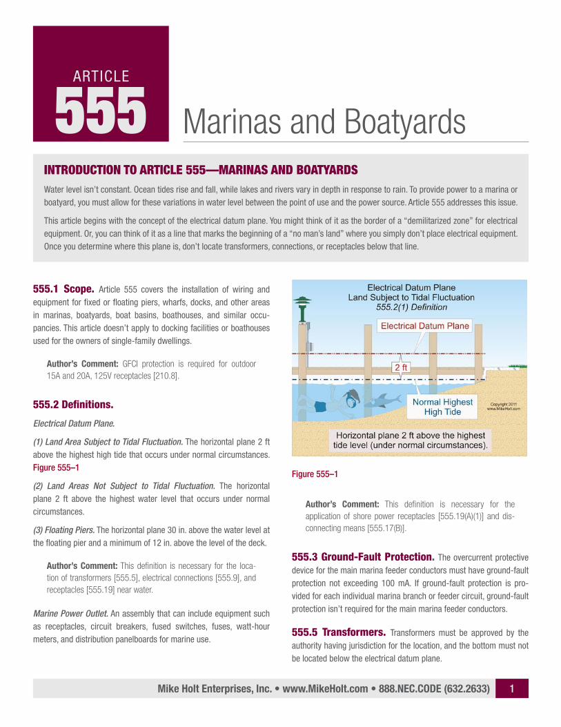
(1) Land Area Subject to Tidal Fluctuation. The horizontal plane 2 ft above the highest high tide that occurs under normal circumstances. Figure 555–1
(2) Land Areas Not Subject to Tidal Fluctuation. The horizontal plane 2 ft above the highest water level that occurs under normal circumstances.
(3) Floating Piers. The horizontal plane 30 in. above the water level at the floating pier and a minimum of 12 in. above the level of the deck.
Author’s Comment: This definition is necessary for the loca-tion of transformers [555.5], electrical connections [555.9], and receptacles [555.19] near water.
Marine Power Outlet. An assembly that can include equipment such as receptacles, circuit breakers, fused switches, fuses, watt-hour meters, and distribution panelboards for marine use.
IntroductIon to ArtIcle 555—MArInAs And BoAtyArdsWater level isn’t constant. Ocean tides rise and fall, while lakes and rivers vary in depth in response to rain. To provide power to a marina or boatyard, you must allow for these variations in water level between the point of use and the power source. Article 555 addresses this issue.
This article begins with the concept of the electrical datum plane. You might think of it as the border of a “demilitarized zone” for electrical equipment. Or, you can think of it as a line that marks the beginning of a “no man’s land” where you simply don’t place electrical equipment. Once you determine where this plane is, don’t locate transformers, connections, or receptacles below that line.
Figure 555–1
Mike Holt Enterprises, Inc. • www.MikeHolt.com • 888.NEC.CODE (632.2633) 2
Marinas and Boatyards
555.7 Location of Service Equipment. Service equip-ment for floating docks or marinas isn’t permitted to be located on the floating structure.
555.9 Electrical Connections.
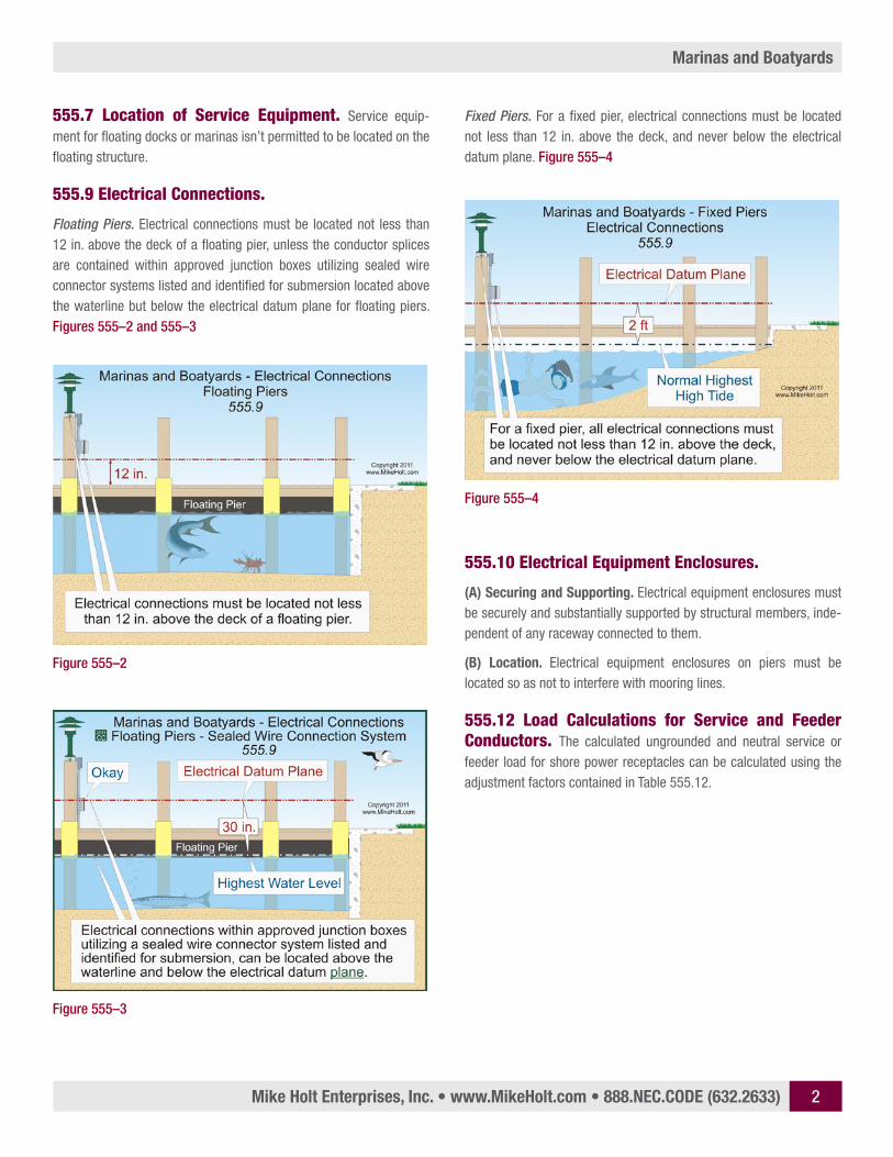
Floating Piers. Electrical connections must be located not less than 12 in. above the deck of a floating pier, unless the conductor splices are contained within approved junction boxes utilizing sealed wire connector systems listed and identified for submersion located above the waterline but below the electrical datum plane for floating piers. Figures 555–2 and 555–3
Fixed Piers. For a fixed pier, electrical connections must be located not less than 12 in. above the deck, and never below the electrical datum plane. Figure 555–4
555.10 Electrical Equipment Enclosures.
(A) Securing and Supporting. Electrical equipment en closures must be se curely and substantially supported by structural members, inde-pendent of any raceway connected to them.
(B) Location. Electrical equipment enclosures on piers must be located so as not to interfere with mooring lines.
555.12 Load Calculations for Service and Feeder Conductors. The calculated ungrounded and neutral service or feeder load for shore power receptacles can be calculated using the adjustment factors contained in Table 555.12.
Figure 555–2
Figure 555–4
Figure 555–3
Mike Holt Enterprises, Inc. • www.MikeHolt.com • 888.NEC.CODE (632.2633) 3
Marinas and Boatyards
Table 555.12 Adjustment Factors
Number of ReceptaclesSum of the Rating of
the Receptacles
1–4 100%
5–8 90%
9–14 80%
15–30 70%
31–40 60%
41–50 50%
51–70 40%
Over 71 30%
Note 1. If shore power provides two receptacles having different voltages for an individual boat slip, only the receptacle with the larger kilowatt demand rating is required to be included in the calculation. Figure 555–5
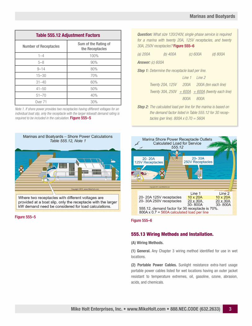
Question: What size 120/240V, single-phase service is required for a marina with twenty 20A, 125V receptacles, and twenty 30A, 250V receptacles? Figure 555–6
(a) 200A (b) 400A (c) 600A (d) 800A
Answer: (c) 600A
Step 1: Determine the receptacle load per line.
Line 1 Line 2
Twenty 20A, 125V 200A 200A (ten each line)
Twenty 30A, 250V + 600A + 600A (twenty each line)
800A 800A
Step 2: The calculated load per line for the marina is based on the demand factor listed in Table 555.12 for 30 recep-tacles (per line). 800A x 0.70 = 560A
555.13 Wiring Methods and Installation.
(A) Wiring Methods.
(1) General. Any Chapter 3 wiring method identified for use in wet locations.
(2) Portable Power Cables. Sunlight resistance extra-hard usage portable power cables listed for wet locations having an outer jacket resistant to temperature extremes, oil, gasoline, ozone, abrasion, acids, and chemicals.
Figure 555–5Figure 555–6
Mike Holt Enterprises, Inc. • www.MikeHolt.com • 888.NEC.CODE (632.2633) 4
Marinas and Boatyards
(B) Installation.
(4) Portable Power Cables.
(a) Portable power cables permitted by 555.13(A)(2) must be:
(1) Supported.
(2) Located on the underside of the pier.
(3) Securely fastened by nonmetallic clips to structural members other than the deck planking.
(4) Not be subject to physical damage.
(5) Protected against chafing by a permanently installed oversized sleeve of nonmetallic material when cables pass through struc-tural members.
(5) Protection. Raceway must be used to protect wiring above decks of piers and landing stages.
555.15 Grounding.
(B) Equipment Grounding Conductor. An insulated copper equip-ment grounding conductor is required for circuits.
(C) Size of Equipment Grounding Conductor. The insulated copper equipment grounding conductor must be sized in accordance with 250.122, but not smaller than 12 AWG.
555.17 Boat Receptacle Disconnecting Means. A disconnecting means must isolate each boat from its shore power receptacle.
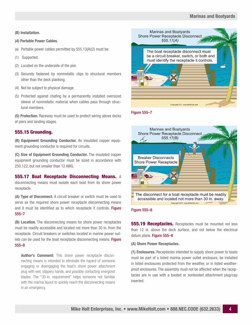
(A) Type of Disconnect. A circuit breaker or switch must be used to serve as the required shore power receptacle disconnecting means and it must be identified as to which receptacle it controls. Figure 555–7
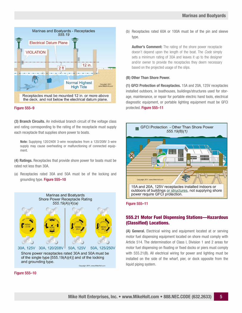
(B) Location. The disconnecting means for shore power receptacles must be readily accessible and located not more than 30 in. from the receptacle. Circuit breakers or switches located in marine power out-lets can be used for the boat receptacle disconnecting means. Figure 555–8
Author’s Comment: This shore power receptacle discon-necting means is intended to eliminate the hazard of someone engaging or disengaging the boat’s shore power attachment plug with wet, slippery hands, and possibly contacting energized blades. The “30-in. requirement” helps someone not familiar with the marina layout to quickly reach the disconnecting means in an emergency.
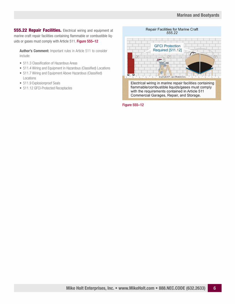
555.19 Receptacles. Receptacles must be mounted not less than 12 in. above the deck surface, and not below the electrical datum plane. Figure 555–9
(A) Shore Power Receptacles.
(1) Enclosures. Receptacles intended to supply shore power to boats must be part of a listed marina power outlet enclosure, be installed in listed enclosures protected from the weather, or in listed weather-proof enclosures. The assembly must not be affected when the recep-tacles are in use with a booted or nonbooted attachment plug/cap inserted.
Figure 555–7
Figure 555–8
Mike Holt Enterprises, Inc. • www.MikeHolt.com • 888.NEC.CODE (632.2633) 5
Marinas and Boatyards
(3) Branch Circuits. An individual branch circuit of the voltage class and rating corresponding to the rating of the receptacle must supply each receptacle that supplies shore power to boats.
Note: Supplying 120/240V 3-wire receptacles from a 120/208V 3-wire supply may cause overheating or malfunctioning of connected equip-ment.
(4) Ratings. Receptacles that provide shore power for boats must be rated not less than 30A.
(a) Receptacles rated 30A and 50A must be of the locking and grounding type. Figure 555–10
(b) Receptacles rated 60A or 100A must be of the pin and sleeve type.
Author’s Comment: The rating of the shore power receptacle doesn’t depend upon the length of the boat. The Code simply sets a minimum rating of 30A and leaves it up to the designer and/or owner to provide the receptacles they deem necessary based on the projected usage of the slips.
(B) Other Than Shore Power.
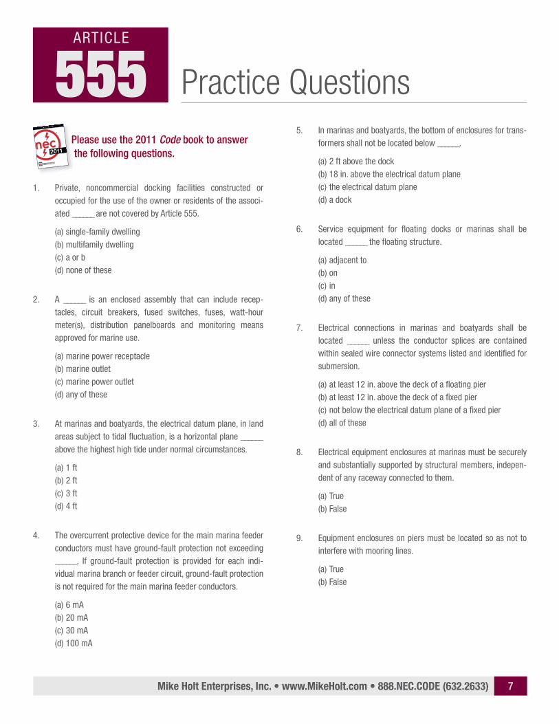
(1) GFCI Protection of Receptacles. 15A and 20A, 125V receptacles installed outdoors, in boathouses, buildings/structures used for stor-age, maintenance, or repair for portable electric hand tools, electrical diagnostic equipment, or portable lighting equipment must be GFCI protected. Figure 555–11
555.21 Motor Fuel Dispensing Stations—Hazardous (Classified) Locations.
(A) General. Electrical wiring and equipment located at or serving motor fuel dispensing equipment located on shore must comply with Article 514. The determination of Class I, Division 1 and 2 areas for motor fuel dispensing on floating or fixed docks or piers must comply with 555.21(B). All electrical wiring for power and lighting must be installed on the side of the wharf, pier, or dock opposite from the liquid piping system.
Figure 555–9
Figure 555–10
Figure 555–11
Mike Holt Enterprises, Inc. • www.MikeHolt.com • 888.NEC.CODE (632.2633) 6
Marinas and Boatyards
555.22 Repair Facilities. Electrical wiring and equipment at marine craft repair facilities containing flammable or combustible liq-uids or gases must comply with Article 511. Figure 555–12
Author’s Comment: Important rules in Article 511 to consider include:
• 511.3 Classification of Hazardous Areas• 511.4 Wiring and Equipment in Hazardous (Classified) Locations• 511.7 Wiring and Equipment Above Hazardous (Classified)
Locations• 511.9 Explosionproof Seals• 511.12 GFCI-Protected Receptacles
Figure 555–12
Mike Holt Enterprises, Inc. • www.MikeHolt.com • 888.NEC.CODE (632.2633) 7
Practice Questions555ARTICLE
Please use the 2011 Code book to answer the following questions.
1. Private, noncommercial docking facilities constructed or occupied for the use of the owner or residents of the associ-ated ______ are not covered by Article 555.
(a) single-family dwelling(b) multifamily dwelling(c) a or b(d) none of these
2. A ______ is an enclosed assembly that can include recep-tacles, circuit breakers, fused switches, fuses, watt-hour meter(s), distribution panelboards and monitoring means approved for marine use.
(a) marine power receptacle(b) marine outlet(c) marine power outlet(d) any of these
3. At marinas and boatyards, the electrical datum plane, in land areas subject to tidal fluctuation, is a horizontal plane ______ above the highest high tide under normal circumstances.
(a) 1 ft(b) 2 ft(c) 3 ft(d) 4 ft
4. The overcurrent protective device for the main marina feeder conductors must have ground-fault protection not exceeding ______. If ground-fault protection is provided for each indi-vidual marina branch or feeder circuit, ground-fault protection is not required for the main marina feeder conductors.
(a) 6 mA(b) 20 mA(c) 30 mA(d) 100 mA
5. In marinas and boatyards, the bottom of enclosures for trans-formers shall not be located below ______.
(a) 2 ft above the dock(b) 18 in. above the electrical datum plane(c) the electrical datum plane(d) a dock
6. Service equipment for floating docks or marinas shall be located ______ the floating structure.
(a) adjacent to(b) on(c) in(d) any of these
7. Electrical connections in marinas and boatyards shall be located ______ unless the conductor splices are contained within sealed wire connector systems listed and identified for submersion.
(a) at least 12 in. above the deck of a floating pier(b) at least 12 in. above the deck of a fixed pier(c) not below the electrical datum plane of a fixed pier(d) all of these
8. Electrical equipment enclosures at marinas must be securely and substantially supported by structural members, indepen-dent of any raceway connected to them.
(a) True(b) False
9. Equipment enclosures on piers must be located so as not to interfere with mooring lines.
(a) True(b) False
Mike Holt Enterprises, Inc. • www.MikeHolt.com • 888.NEC.CODE (632.2633) 8
Marinas and Boatyards
10. The demand factor for marina load calculations of 45 shore power receptacles is ______ percent.
(a) 40(b) 50(c) 60(d) 70
11. Where shore power accommodations provide two receptacles specifically for an individual boat slip, and these receptacles have different voltages, only the receptacle with the ______ shall be required to be calculated.
(a) smaller kW demand(b) larger kW demand(c) higher voltage(d) none of these
12. The equipment grounding conductor at a marina is required to be an insulated copper conductor for all circuits.
(a) True(b) False
13. Disconnecting means shall be provided to ______ each boat from its supply connection(s). The disconnecting means shall consist of a circuit breaker, switch, or both, and shall identify which receptacle it controls.
(a) isolate(b) separate(c) guard(d) control
14. A ______ must be used to serve as the required shore power receptacle disconnecting means and it must be identified as to which receptacle it controls.
(a) circuit breaker(b) switch (c) a and b(d) a or b
15. In marinas or boatyards, the NEC requires a(n) ______ discon-necting means, which allows individual boats to be isolated from their supply connection.
(a) accessible(b) readily accessible(c) remote(d) any of these
16. The disconnecting means for a shore power connection shall be not more than ______ from the receptacle it controls.
(a) 12 in.(b) 24 in.(c) 30 in.(d) 36 in.
17. Supplying 120/240V 3-wire shore power receptacles from a 120/208V 3-wire supply may cause overheating or malfunc-tioning of connected equipment.
(a) True(b) False
18. Receptacles that provide shore power for boats shall be rated not less than ______.
(a) 15A(b) 20A(c) 30A(d) 60A
19. Fifteen and 20A, single-phase, 125V receptacles used for other than shore power in marinas but not installed in marine power outlets shall be provided with ______.
(a) lockouts(b) GFCI protection(c) warning labels(d) all of these
20. Electrical wiring for______ shall be installed on the side of the wharf, pier, or dock opposite from the liquid fuel piping system.
(a) power(b) lighting(c) fuel dispensing equipment(d) all of these

Mike Holt Enterprises, Inc. • www.MikeHolt.com • 888.NEC.CODE (632.2633) 9
1. (a) 555.12. (c) 555.2 Marine Power Outlet3. (b) 555.2 Electrical Datum Plane4. (d) 555.35. (c) 555.56. (a) 555.77. (d) 555.98. (a) 555.10(A)9. (a) 555.10(B)10. (b) 555.12 Table11. (b) 555.12, Note 112. (a) 555.15(B)13. (a) 555.17(A)14. (d) 555.17(A)15. (b) 555.17(B)16. (c) 555.17(B)17. (a) 555.19(A)(3) Note18. (c) 555.19(A)(4)19. (b) 555.19(B)(1)20. (d) 555.21(A)
Practice Question Answers555ARTICLE