bentleyuser.dk Årsmøde 2009 nordic civil 2009 · 2013-07-05 · bentleyuser.dk Årsmøde 2009...
TRANSCRIPT

Bentleyuser.dk Årsmøde 2009
Nordic Civil 2009 9.-11. November 2009, Munkebjerg Hotel, Vejle
Workshop - X13 Advanced Geometric Design for InRoads V8i
Presenter: Edmundo Herrera, P.E., Bentley Systems USA
Bentley Systems, Incorporated 685 Stockton Drive Exton, PA 19341 www.bentley.com

2009 NORDIC CONFERENCE
ADVANCED GEOMETRIC DESIGN FOR INROADS V8I
© 2009 Bentley Systems, Incorporated Page 2
1. 1. LESSON NAME: SETUP GEOMETRY OPTIONS
LESSON OBJECTIVE: This lesson will show how to setup the new Geometry Options during the design process.
1.1 EXERCISE: SETTING UP THE NEW GEOMETRY OPTIONS This exercise will guide you through the steps to get started
1. Load the file road_imperial.dgn
2. Load the project file Road.rwk
3. Go to Geometry > View Geometry > Options …
As create or edit alignments the software updates most annotation. Specifically the software updates the following:
• Horizontal Elements • Vertical Elements • Closed Areas • Stationing • Curve Sets • Vertical Change in Plan • View Horizontal & Vertical Regression Points
Whether or not annotation is updated during edits is based on the following:
• You must have an option to update the annotation that you want to annotate. • You must have a means to control the annotation. In other words, while it may be appropriate to annotate an alignment with stationing, it may be inappropriate to annotate a boundary/parcel with stationing.
Check on the following check boxes to specify to update the associated annotation.

2009 NORDIC CONFERENCE
ADVANCED GEOMETRIC DESIGN FOR INROADS V8I
© 2009 Bentley Systems, Incorporated Page 3
Note:
The appearance of the annotation is controlled by each Geometry > View commands preferences by
using the alignment’s style and view commands preference. Example, you have an alignment with a
style called DESIGN CENTERLINE. If you checked on that you want to annotate the stationing then you
must save a View Station preference called DESIGN CENTERLINE. If such a preference is defined then
the software displays and annotates the stationing based upon the settings for DESIGN CENTERLINE.
The software does not look at the settings for View Stationing that are in memory. The preference
must exist on disk or the software silently skips the stationing annotation.
4. View the Perimeter Surface > View Surface > Perimeter …
2. LESSON NAME: USING THE NEW GEOMETRY VIEW OPTIONS
LESSON OBJECTIVE: This lesson will show how to use the new Geometry Options
2.1 EXERCISE: USING GEOMETRY > VIEW OPTIONS This exercise will guide you through the steps to use the new options
1. Create a new horizontal & vertical alignment

2009 NORDIC CONFERENCE
ADVANCED GEOMETRIC DESIGN FOR INROADS V8I
© 2009 Bentley Systems, Incorporated Page 4
Close the dialog box
2. Use the horiz. PI – Method or Element Method and design a simple horiz. alignment
Insert a horizontal curve
3. Check Geometry > View Geometry > Stationing > Preference …

2009 NORDIC CONFERENCE
ADVANCED GEOMETRIC DESIGN FOR INROADS V8I
© 2009 Bentley Systems, Incorporated Page 5
There 2 preferences with different annotation settings.
Default
DEFINE CENTERLINE
Close the dialog box.

2009 NORDIC CONFERENCE
ADVANCED GEOMETRIC DESIGN FOR INROADS V8I
© 2009 Bentley Systems, Incorporated Page 6
Go to Geometry > View Geometry > View Options > …
By Default all annotation is turned off.
Load a preference called DESIGN CENTERLINE
All Annotation is turned on for the design process.
Move on with the alignment creation
The software annotates during the design process all stationing values from the View Stationing settings.

2009 NORDIC CONFERENCE
ADVANCED GEOMETRIC DESIGN FOR INROADS V8I
© 2009 Bentley Systems, Incorporated Page 7
4. Create a profile turn the dtm on
5. Use the vert. PI – Method or Element Method and design a simple vert. alignment

2009 NORDIC CONFERENCE
ADVANCED GEOMETRIC DESIGN FOR INROADS V8I
© 2009 Bentley Systems, Incorporated Page 8
6. Annotate the vertical alignment Geometry > View Geometry > Vertical Annotation
There 2 different preferences for different annotation
Load the preference DESIGN CENTERLINE

2009 NORDIC CONFERENCE
ADVANCED GEOMETRIC DESIGN FOR INROADS V8I
© 2009 Bentley Systems, Incorporated Page 9
7. Use the different View Geometry Options by loading the different preferences and view the results during the design process

2009 NORDIC CONFERENCE
ADVANCED GEOMETRIC DESIGN FOR INROADS V8I
© 2009 Bentley Systems, Incorporated Page 10
3. LESSON NAME: USING THE DESIGN CALCULATOR
LESSON OBJECTIVE: This lesson will show how to work with the design calculator during the horizontal alignment creation.
3.1 EXERCISE: SETTING UP THE NEW SIMPLIFIED GEOMETRY TOOLS This exercise will guide you through the steps to get started with the Design Calculator
1. You need to have an active horizontal alignment
2. Go to Geometry > Horizontal Curve Set > Define Horizontal Curve …
3. Use the Design Calculator
4. Use the Table Lookups

2009 NORDIC CONFERENCE
ADVANCED GEOMETRIC DESIGN FOR INROADS V8I
© 2009 Bentley Systems, Incorporated Page 11
5. Select the Table name
6. You will find the table name in the product directory under … \data\imperial\Horizontal Design Checks.txt or …\data\metric\Horizontal Design Checks.txt

2009 NORDIC CONFERENCE
ADVANCED GEOMETRIC DESIGN FOR INROADS V8I
© 2009 Bentley Systems, Incorporated Page 12
The user can now look for different design checks
Or can select different speeds.

2009 NORDIC CONFERENCE
ADVANCED GEOMETRIC DESIGN FOR INROADS V8I
© 2009 Bentley Systems, Incorporated Page 13
Upon these values the software will calculate the required radius.
Note:
Clicking the Design Calc button on the Define Horizontal Curve Set dialog box activates this
dialog.
The Table Lookups tab works as follows: After you have specified the Method field, key in any
of the relevant values, then press the tab key to see the results of the computation. As you
change the data in the dialog, the software automatically recomputes all parameters. Once
you have settled on a calculation, click OK to post the Radius back to the parent dialog.
Tab Options
Method

2009 NORDIC CONFERENCE
ADVANCED GEOMETRIC DESIGN FOR INROADS V8I
© 2009 Bentley Systems, Incorporated Page 14
defines the method for calculating the horizontal curve.
Compute Radius – computes the radius for horizontal curves using the following equations:
English - R=V^2/[15(e+f)], where R is the radius (ft), V is the vehicle speed (mph), e is the rate
of roadway superelevation (ft/ft), and f is the side friction factor
Metric - R=V^2/[127(e/100+f)], where R is the radius (m), V is the vehicle speed (kmh), e is the
rate of roadway superelevation (m/m), and f is the side friction factor
Compute Speed – computes the speed using the equations for the compute radius method for
imperial and metric units.
Lookup Radius – reads the values for radius, maximum f and speed values varying the rate of
superelevation. These values are read from an ASCII file specified under Table Name and
contains information from “A Policy on Geometric Design of Highways and Streets 1994” for
imperial and metric units.
Lookup Speed – reads in the values for radius, maximum f and maximum e varying the vehicle
speed. These values are read from an ASCII file specified under Table Name and contains
information from “A Policy on Geometric Design of Highways and Streets 1994” for imperial
and metric units.

2009 NORDIC CONFERENCE
ADVANCED GEOMETRIC DESIGN FOR INROADS V8I
© 2009 Bentley Systems, Incorporated Page 15
You can save the settings as a preference.
Hit OK. The software will take the required radius into the Define Horizontal Curve dialog box.

2009 NORDIC CONFERENCE
ADVANCED GEOMETRIC DESIGN FOR INROADS V8I
© 2009 Bentley Systems, Incorporated Page 16
Apply will save the curve value to the alignment. Close the dialog box.

2009 NORDIC CONFERENCE
ADVANCED GEOMETRIC DESIGN FOR INROADS V8I
© 2009 Bentley Systems, Incorporated Page 17
4. LESSON NAME: SIMPLIFIED GEOMETRY TOOLS
LESSON OBJECTIVE: This lesson will show how to setup the new simplified geometry tools.
4.1 EXERCISE: SETTING UP THE NEW SIMPLIFIED GEOMETRY TOOLS
4.2 HORIZONTAL DESIGN This exercise will guide you through the steps to get started with the Simplified Geometry Tools
1. Create a new horizontal alignment
2. Setup your horizontal geometry settings
Leading Transition
defines the leading transition spiral’s length or constant. This field honors Tools > Options >
Geometry and Define Transitions by Length or Constant.
Radius
defines the circular arc’s radius.
Trailing Transition
defines the trailing transition spiral’s length or constant. This field honors Tools > Options >
Geometry and Define Transitions by Length or Constant.
Design Calculator
invokes the design calculator to define the transition lengths and radius from design criteria.
Note: This dialog should remain active while using the Simplified Horizontal Elements
commands. As you change settings on this dialog, commands that use these settings instantly
reflect these settings.

2009 NORDIC CONFERENCE
ADVANCED GEOMETRIC DESIGN FOR INROADS V8I
© 2009 Bentley Systems, Incorporated Page 18
3. Do the following settings:
4. Start the design process with Add Fixed Line:
The command works a little bit different then the Horizontal Element Method.
5. Fill the gaps with the Add Free Curve command.
The software takes the values from the settings.
6. Add a Floating Curve and use these settings:

2009 NORDIC CONFERENCE
ADVANCED GEOMETRIC DESIGN FOR INROADS V8I
© 2009 Bentley Systems, Incorporated Page 19
7. Add a Fixed Curve with the following settings
If you have a solution like shown
you can fill a reverse spiral between reverse arcs.
8. Use Define Spiral
The reverse spirals have the same parameter.
2009 NORDIC CONFERENCE
ADVANCED GEOMETRIC DESIGN FOR INROADS V8I
© 2009 Bentley Systems, Incorporated Page 20
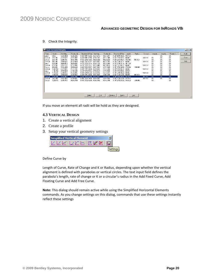
9. Check the Integrity.
If you move an element all radii will be hold as they are designed.
4.3 VERTICAL DESIGN 1. Create a vertical alignment
2. Create a profile
3. Setup your vertical geometry settings
Define Curve by
Length of Curve, Rate of Change and K or Radius, depending upon whether the vertical
alignment is defined with parabolas or vertical circles. The text input field defines the
parabola’s length, rate of change or K or a circular’s radius in the Add Fixed Curve, Add
Floating Curve and Add Free Curve.
Note: This dialog should remain active while using the Simplified Horizontal Elements
commands. As you change settings on this dialog, commands that use these settings instantly
reflect these settings

2009 NORDIC CONFERENCE
ADVANCED GEOMETRIC DESIGN FOR INROADS V8I
© 2009 Bentley Systems, Incorporated Page 21
4. Create a Fixed Vertical Line
5. Add a Free Vertical Curve
6. Add a Floating Curve
7. Add Fixed Curve

2009 NORDIC CONFERENCE
ADVANCED GEOMETRIC DESIGN FOR INROADS V8I
© 2009 Bentley Systems, Incorporated Page 22
8. Use the following settings
You may have this solution:
9. Use Add Free Line
And fill the gap between the reverse vertical arcs.

2009 NORDIC CONFERENCE
ADVANCED GEOMETRIC DESIGN FOR INROADS V8I
© 2009 Bentley Systems, Incorporated Page 23
5. LESSON NAME: HORIZONTAL ELEMENT
LESSON OBJECTIVE: This exercise will guide you through the steps to get started with Fixed
Elements
5.1 EXERCISE: ADD FIXED ELEMENTS This exercise will guide you through the steps to get started with Fixed Elements
1. Create a new horizontal alignment
2. Create New cogo points (3 new cogo points)
Geometry > Cogo Points > New ..
You may have this result:
3. Add Fixed Horizontal Elements

2009 NORDIC CONFERENCE
ADVANCED GEOMETRIC DESIGN FOR INROADS V8I
© 2009 Bentley Systems, Incorporated Page 24
Use this command to add a fixed element using point, length or delta as controls then adds the
solution to the alignment. This command is limited to clothoid spirals. creates the element and
displays it into the alignment.
The element type is determined by the following rules:
Linear: Point 1’s Radius and Point 2’s Radius is zero
Circular: Point 1’s Radius and Point 2’s Radius is equal and non-zero

2009 NORDIC CONFERENCE
ADVANCED GEOMETRIC DESIGN FOR INROADS V8I
© 2009 Bentley Systems, Incorporated Page 25
Spiral: Point 1’s Radius and Point 2’s Radius is non-equal and like sign
When the software successfully creates the element, this element is added to the undo buffer
(single element undo).
Also the Point 1 data is updated with the computed data from computed element. This
facilitates creating an alignment from a single interface and with the minimum number of data
points.

2009 NORDIC CONFERENCE
ADVANCED GEOMETRIC DESIGN FOR INROADS V8I
© 2009 Bentley Systems, Incorporated Page 26
6. LESSON NAME: SEGMENT ALIGNMENT
LESSON OBJECTIVE: This lesson will show how to use the Segment Alignment Utility
6.1 EXERCISE: SEGMENT ALIGNMENT This lesson will guide you how to use the Segment Alignment Utility
1. Load Segment.alg
2. Use the Segmentation Utility Geometry > Utilities > Segment Alignment
Apply.
Constructs a line by division or proportion along a line, constructs an arc by division or
proportion along an arc or curve.
3. Check the horiz. Integrity an review the results

2009 NORDIC CONFERENCE
ADVANCED GEOMETRIC DESIGN FOR INROADS V8I
© 2009 Bentley Systems, Incorporated Page 27
7. LESSON NAME: CHAIN POINTS
LESSON OBJECTIVE: This lesson will show how to use the Chain Points Utility
7.1 EXERCISE: CHAIN POINTS BY COGO POINTS This lesson will guide you how to use the Chain Points Utility
1. Load Chain Points.alg
2. View the cogo points

2009 NORDIC CONFERENCE
ADVANCED GEOMETRIC DESIGN FOR INROADS V8I
© 2009 Bentley Systems, Incorporated Page 28
3. Use the Utility Geometry > Utilities > Chain Points by alignment
Apply & Identify the 1st points then the 2nd point
The magenta line views the bandwidth of 30 ft or m
Hint: Turn the Cogo Snap Lock ON

2009 NORDIC CONFERENCE
ADVANCED GEOMETRIC DESIGN FOR INROADS V8I
© 2009 Bentley Systems, Incorporated Page 29
The result should look like this:
7.2 EXERCISE: CHAIN POINTS FOR FEATURES 4. Create a surface
5. Turn the Feature check box ON.

2009 NORDIC CONFERENCE
ADVANCED GEOMETRIC DESIGN FOR INROADS V8I
© 2009 Bentley Systems, Incorporated Page 30
6. Apply
Identify the points you want to create a feature on.
7. Surface > View Surface > Features
2009 NORDIC CONFERENCE
ADVANCED GEOMETRIC DESIGN FOR INROADS V8I
© 2009 Bentley Systems, Incorporated Page 31
8. LESSON NAME: CURVE FITTING
LESSON OBJECTIVE: This lesson will show how to use the curve fitting utility to find the best fit alignment between 2 lines
8.1 EXERCISE: This lesson will show how to use the curve fitting utility to find the best fit alignment between 2 lines
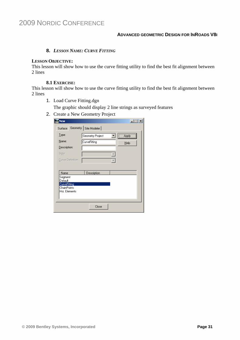
1. Load Curve Fitting.dgn The graphic should display 2 line strings as surveyed features
2. Create a New Geometry Project

2009 NORDIC CONFERENCE
ADVANCED GEOMETRIC DESIGN FOR INROADS V8I
© 2009 Bentley Systems, Incorporated Page 32
3. Import Geometry from Graphic lines
File > Import > Geometry > From Graphics …
4. Create a Best Fit Alignment between control line
Uses a 3D line-string, in the form of a horizontal alignment, and creates a new horizontal alignment and vertical alignment that is defined with lines and arcs. The resultant geometry passes within a user-defined tolerance of the point data. Curve Fitting does not create transition spirals. Transition spirals are created by Quick regression Analysis. Visit the rail seminar. The Curve Fitting command’s source data is an alignment defined as a line-string with xyz values. Quick regression’s source is a regression buffer. Use this command to curve fit a horizontal and vertical alignment.

2009 NORDIC CONFERENCE
ADVANCED GEOMETRIC DESIGN FOR INROADS V8I
© 2009 Bentley Systems, Incorporated Page 33
The software has been created a new horizontal alignment.
5. Check Integrity

2009 NORDIC CONFERENCE
ADVANCED GEOMETRIC DESIGN FOR INROADS V8I
© 2009 Bentley Systems, Incorporated Page 34
As you can see there some issues with the colinearity. You can try to get a better geometrical result if you set the tolerance higher.