ars-700 - churchill navigation · ars-700 is the next-generation mission platform developed by...
TRANSCRIPT

0
ARS-700 Installation Manual Rev. 1.1

Churchill Navigation Support ● Phone: 720.744.3300 ● E-mail: [email protected] 2
Rev Number
Description Date
1.0 1.1
Original document release Miscellaneous updates
MAY 2017 AUG 2017

Churchill Navigation ● Support Phone: 720.744.3300 ● E-mail: [email protected] 3
Table of Contents
Section 1: Background .......................................................................................................... 5
Section 2: Installation Guidelines ......................................................................................... 9
Section 3: Cabling & Connectors ......................................................................................... 11
Section 4: Aircraft Post-Installation Testing Procedures ...................................................... 18
Section 5: Technical Supplement ........................................................................................ 21

Churchill Navigation ● Support Phone: 720.744.3300 ● E-mail: [email protected] 4
Notice:
The information contained in this document is considered confidential and proprietary to Churchill Navigation. Neither the document nor the information contained therein should be disclosed or reproduced in whole or in part, without express written consent of Churchill Navigation. Changes or modifications not expressly approved by Churchill Navigation could void the user’s authority to operate the equipment. Non-Churchill Navigation part numbers referenced in this manual are not maintained by Churchill Navigation and may be subject to change without notice. All information depicted in this manual, including hardware and software names, versions, and part numbers, is subject to change and may not be up to date.
About this Manual This manual describes the physical, mechanical, and electrical components, as well as instructions for the installation of the Churchill Navigation ARS-700. Every effort has been made to make this document as complete and accurate as possible.
The following symbols for warnings, cautions, and notes are used to throughout this manual.
Warning
A warning symbol denotes an item where a potential hazard capable of producing injury to personnel or destruction of equipment exists if the approved procedure is not followed.
Caution
A caution symbol denotes an item where, if not followed, damage to equipment or degradation of mission capability can occur.
Note
The note symbol is used to identify essential information for installers / operators. While not directly related to safety or protection of equipment from damage, the note symbol identifies information to which attention should be paid during the installation and/or operation of the equipment.
Product Guarantee & Warranty Information For details about the Churchill Navigation warranty, please see the Terms and Conditions page available at www.churchillnavigation.com/agreement
This document contains information that was current as of the printing of this manual. To obtain always up-to-date installation drawings, ICDs, and much more, visit: www.churchillnavigation.com/specifications
!
!

Churchill Navigation ● Support Phone: 720.744.3300 ● E-mail: [email protected] 5
Section 1: Background
1.0 Description ARS-700 is the next-generation mission platform developed by Churchill Navigation. At the core of the ARS-700 platform is the ATOM mission computer. ATOM provides the hardware optimized to run Churchill Navigation’s Augmented Reality Mapping software and to provide high quality, digital video recording. ARS-700 operators can interface with a wide varity of external mission equipment, data feeds, and video sources providing an incredibly powerful, yet compact mission solution.
1.1 Components ATOM Mission Computer The ARS-700 platform is based on the ATOM mission computer. ATOM is a compact, solid-state mission computer designed to run the next generation of Churchill Navigation’s Augmented Reality Mapping Software (ARS). ATOM’s design delivers maximum performance in a flexible, lightweight design. Installation Components & Connectors Each ARS-700 will ship with the connectors necessary for proper installation. This includes connectors for Ethernet, power, and serial connections. Installers may purchase an installation wiring kit to ensure recommended connectors are present at the time of installation. ION Digital Video Recorder (Optional) Some operators may elect to purchase Churchill Navigation’s ION digital video recorder for even more flexibility and utility. ION provides a dedicated hardware solution that can record geospatial video directly to hot-swappable SD or USB media, display recorded video on a built-in screen, and allow review and playback while recording.
Specifications Specifications
Churchill Navigation ● Support Phone: 720.744.3300 ● E-mail: [email protected] 6
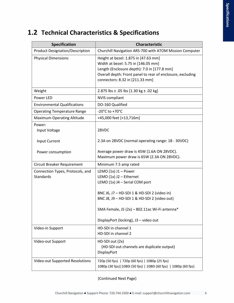
1.2 Technical Characteristics & Specifications
Specification Characteristic Product Designation/Description Churchill Navigation ARS-700 with ATOM Mission Computer
Physical Dimensions Height at bezel: 1.875 in [47.63 mm] Width at bezel: 5.75 in [146.05 mm] Length (Enclosure depth): 7.0 in [177.8 mm] Overall depth: Front panel to rear of enclosure, excluding connectors: 8.32 in [211.33 mm]
Weight 2.875 lbs ± .05 lbs [1.30 kg ± .02 kg]
Power LED NVIS compliant
Environmental Qualifications DO-160 Qualified
Operating Temperature Range -20°C to +70°C Maximum Operating Altitude +45,000 feet [+13,716m]
Power: Input Voltage Input Current Power consumption
28VDC
2.3A on 28VDC (normal operating range: 18 - 30VDC)
Average power draw is 45W (1.6A ON 28VDC). Maximum power draw is 65W (2.3A ON 28VDC).
Circuit Breaker Requirement Minimum 7.5 amp rated
Connection Types, Protocols, and Standards
LEMO (1x) J1 – Power LEMO (1x) J2 – Ethernet LEMO (1x) J4 – Serial COM port BNC J6, J7 – HD-SDI 1 & HD-SDI 2 (video in) BNC J8, J9 – HD-SDI 1 & HD-SDI 2 (video out)
SMA Female, J5 (2x) – 802.11ac Wi-Fi antenna* DisplayPort (locking), J3 – video out
Video-in Support HD-SDI in channel 1 HD-SDI in channel 2
Video-out Support HD-SDI out (2x) (HD-SDI out channels are duplicate output) DisplayPort
Video-out Supported Resolutions 720p (50 fps) | 720p (60 fps) | 1080p (25 fps) 1080p (30 fps)|1080i (50 fps) | 1080i (60 fps) | 1080p (60 fps)
Specifications
(Continued Next Page)

Churchill Navigation ● Support Phone: 720.744.3300 ● E-mail: [email protected] 7
Metadata Standard KLV MISB/STANAG 4609 compliant
Video Codecs H.264 (MPEG-4 AVC) H.262 (MPEG-2)
* 802.11ac Wi-Fi available for approved installations only.
1.3 ATOM Front Panel Design Features The front connections and features of the ATOM are described below.
1) USB 3.0 2) USB 3.0 (charging capable) 3) Ventilation with user-serviceable air filter 4) Female SMA connector: Wi-Fi 5) Power LED 6) Removable drive bay (for data drive) 7) CMOS Battery access tray (located on the bottom of the enclosure) *
3
6
1 2 5
Specifications
4
Specifications
7
Churchill Navigation ● Support Phone: 720.744.3300 ● E-mail: [email protected] 8
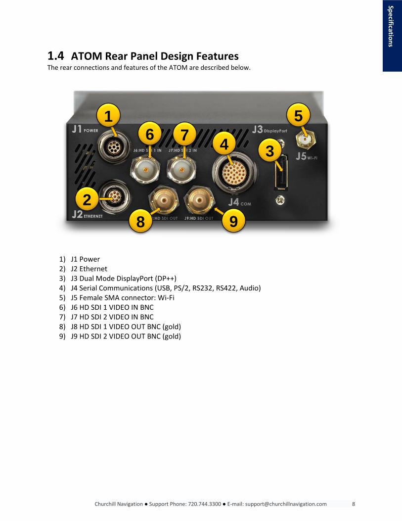
1.4 ATOM Rear Panel Design Features The rear connections and features of the ATOM are described below.
1) J1 Power 2) J2 Ethernet 3) J3 Dual Mode DisplayPort (DP++) 4) J4 Serial Communications (USB, PS/2, RS232, RS422, Audio) 5) J5 Female SMA connector: Wi-Fi 6) J6 HD SDI 1 VIDEO IN BNC 7) J7 HD SDI 2 VIDEO IN BNC 8) J8 HD SDI 1 VIDEO OUT BNC (gold) 9) J9 HD SDI 2 VIDEO OUT BNC (gold)
1 6 7 4
5
3
2 8 9
Specifications

Churchill Navigation ● Support Phone: 720.744.3300 ● E-mail: [email protected] 9
Section 2: Installation Guidelines
2.0 Description This section contains information and instructions for the unpacking and correct installation of the Churchill Navigation ARS-700 hardware.
2.1 Equipment Packaging Prior to installation, carefully inspect all supplied hardware. Note any damage that may have occurred in transit and contact the parcel carrier if necessary to file a claim. If possible, retain the original packaging to ease in the claim or return process. Check that all items listed below are present prior to proceeding with the installation. Report any missing items to your supplier.
- (1) ATOM Mission Computer - (1) ARS-700 Connector Kit - Product manuals and guides
2.2 ARS-700 Connector Kit Each ARS-700 includes an ARS-700 Connector Kit. This kit contains all recommended connectors and accessories needed for installation. Additional connectors are available for purchase from Churchill Navigation or direct from the manufacturers themselves. The connector kit includes the following:
ARS-700 Connector Kit Contents Qty Churchill Navigation
Part Number Manufacturer’s Part Number Application
1 1 1 4 4 4 2 1 4 4 1
CONN-PR-308 CONN-ETH-308 CONN-SER-330 CONN-PIC CONN-RG59 CONN-RG179 CONN-SR-9N CONN-SR-13N CONN-FER-S CONN-FER-L CONN-FER-K
LEMO FGN.1M.308.XLCM LEMO FGU.1M.308.XLCM LEMO FGN.3M.330.XLCM Pic Wire & Cable 190712 Amphenol 112123 Amphenol 112133 Amphenol M85049/38-9N Amphenol M85049/38-13N Würth Elektronik 74271142S Würth Elektronik 74271112S Würth Elektronik 74271
Power Connector Ethernet Connector Serial COM Connector Coaxial BNC Connector (75Ω) RG59 Coaxial BNC Connector (75Ω) RG179 Coaxial BNC Connector (75Ω) Strain relief connector Strain relief connector Small snap on ferrite Large snap on ferrite Ferrite key
Installation

Churchill Navigation ● Support Phone: 720.744.3300 ● E-mail: [email protected] 10
2.3 Required Tools You will need the correct crimping tool for the connectors selected. A few examples are listed below and are available from Churchill Navigation or from their respective manufacturers. BNC Connectors:
Application Connector: Crimp Die: 75ohm BNC plug for PIC Wire V73263 PIC Wire P/N 190712 M22520/5-41 75ohm BNC plug for RG59 Amphenol P/N 112123 .255/.213/.068 75ohm BNC plug for RG179 Amphenol P/N 112133 .178/.128/.068
All LEMO Connectors:
Crimp Tool Pin Positioner Pin Extractor DPC.91.701.V DCE.91.070.5MVC DCF.93.070.4LT
2.4 Installation Location Considerations The ATOM is intended for DZUS mount (or similar) installations. If you are unsure of the installation location, please contact Churchill Navigation. If possible, ARS-700 mission equipment, displays, and the camera gimbal should be installed on a mission bus separate from avionics and/or master power. If installing the optional ION Digital Video Recorder with the ATOM, it is permissible to place both components up to 100 feet (30.5 meters) apart without any noticeable latency in communications.
To ensure adequate airflow to the unit, Churchill Navigation recommends a minimum of 4 inches / 100mm between the back of the ATOM and any adjacent surface.
2.4.1 Voltage Requirements ATOM operates on 28-volt DC power and consumes a maximum of 80 watts (2.86 amps on 28VDC). However, the hardware will remain operable with voltages ranging from 20-30VDC. Churchill Navigation recommends using 28VDC with a minimum 7.5-amp circuit breaker.
2.4.2 Ground Considerations ATOM is case-grounded through the DZUS mount. Exposed aluminum is chromated. Do not chemically coat or cover with any non-conductive material. All ground pins except 28V return are ground continuous to case.
Failure to properly ground the units may result in damage to the hardware or other installed electrical components.
2.4.3 Service Loop Install all cables with at least an 8 inch [203 mm] service loop to allow for easy removal for servicing.
!
Installation Installation

Churchill Navigation ● Support Phone: 720.744.3300 ● E-mail: [email protected] 11
Section 3: Cabling & Connectors 3.0 Description The cabling descriptions included in this section are highly recommended. Any variation will be at the sole responsibility of the installer. Detailed installation diagrams are provided in this manual and are available at churchillnavigation.com/specifications
When populating LEMO connectors, please follow the pattern on the rear of the male LEMO. On most connectors, the number 1 pin will be identified by a semi-circular ( ) shape around the pin as shown to the right.
3.1 J1 Power Install the J1 Power connector using the supplied LEMO circular connector, Churchill Navigation p/n CONN-PR-308, and CONN-SR-9N circular, strain relief connector clamp. In all cases, the strain relief connector should be installed on the corresponding cable before installing the LEMO connector. The connection to 28VDC input and 28VDC GND are highly recommended to be a twisted pair. Use of 22 AWG wire size is also recommended.
3.1.1 CONN-PR-308 Power Pinout
Pin Function 1 28V 2 GND 3 NC 4 NC 5 NC 6 NC 7 NC 8 NC
CONN-PR-308 (LEMO FGN.1M.308.XLCM)
CONN-SR-9N (Amphenol M85049/38-9N)
!
Installation

Churchill Navigation ● Support Phone: 720.744.3300 ● E-mail: [email protected] 12
3.1.2 CONN-SR-9N Churchill Navigation recommends using the supplied Amphenol circular strain relief connector clamp for all installations. Always install this connector before the LEMO connector.
3.2 J2 Ethernet Camera gimbal geospatial (position) data connectivity requires either J2 Ethernet connection or J4 Serial COM connection. Please contact your gimbal manufacturer if you are unsure which is the preferred method for your setup. Install the J2 Ethernet connector using the supplied LEMO circular connector, Churchill Navigation p/n CONN-ETH-308, and CONN-SR-9N circular, strain relief connector clamp. Churchill Navigation recommends using either Pic Wire & Cable PIC E50824 or EMTEQ D100-0824-006 4-pair Ethernet cable. Either can be purchased from Churchill Navigation or directly from their respective manufacturers at http://www.picwire.com or http://www.emteq.com
3.2.1 CONN-PR-308 Ethernet Pinout Ethernet twisted pair is indicated by color block shown below.
Pin Function Wire color 1 TX-/BiD1- Orange 2 TX+/BiD1+ Orange/White 3 RX-/BiD2- Green 4 RX+/BiD2+ Green/White 5 BiD4- Brown 6 BiD4+ Brown/White 7 BiD3- Blue 8 BiD3+ Blue/White
3.2.2 CONN-SR-9N
Churchill Navigation recommends using the supplied Amphenol circular strain relief connector clamp for all installations. Always install this connector before the LEMO connector.
CONN-PR-308 (LEMO FGU.1M.308.XLCM)
CONN-SR-9N (Amphenol M85049/38-9N)
Installation

Churchill Navigation ● Support Phone: 720.744.3300 ● E-mail: [email protected] 13
3.3 J3 DisplayPort (DP++) ATOM has provisions for dual-mode DisplayPort video output. The J3 port provides display output capability and is useful to act as a primary or secondary display, and/or for on-ground maintenance activities. Any consumer-grade dual-mode DisplayPort cable will be compatible with the output. DisplayPort performance cannot be guaranteed at cable lengths greater than 25 feet (7.62 meters) without the use of an extender.
3.4 J4 COM Install the J4 COM connector using the supplied LEMO circular connector, Churchill Navigation p/n CONN-SER-330, and CONN-SR-13N circular, strain relief connector clamp.
3.4.1 CONN-PR-308 COM Pinout
Pin Function 1 AUDIO OUT (L) 2 USB D- 3 USB D+ 4 USB 5V 5 PS/2 5V 6 PS/2 CLK MOUSE 7 PS/2 DATA KEYB 8 PS/2 CLK KEYB 9 RS232A TX
10 RS232A RX 11 RS232C RX 12 RS232B TX 13 RS422 TX+ * 14 RS422 RX- * 15 RS422 RX+ *
Pin Function 16 AUDIO IN (L) 17 AUDIO IN (R) 18 AUDIO OUT (R) 19 GND (USB) 20 PS/2 DATA MOUSE 21 GND (PS/2) 22 GND (232A) 23 RS232C TX 24 RS232B RX 25 RS422 TX- * 26 GND (RS422) 27 GND (AUDIO) 28 GND (AUDIO) 29 GND (RS232C) 30 GND (RS232B)
* Twisted pair required. Pair RS422 TX+ with TX-, and RS422 RX+ with RX-
CONN-PR-308 (LEMO FGN.3M.330.XLCM)
CONN-SR-13N (Amphenol M85049/38-13N)
Installation

Churchill Navigation ● Support Phone: 720.744.3300 ● E-mail: [email protected] 14
3.4.2 CONN-SR-13N Churchill Navigation recommends using the supplied Amphenol circular strain relief connector clamp for all installations. Always install this connector before the LEMO connector.
3.4.3 USB
For USB applications using J4, Churchill Navigation recommends the following: Option A: Carlisle 28433/02171LX-4. This cable can be purchased directly from Carlisle: http://www.carlisleit.com Option B: EMTEQ U090-0422-100: This cable can be purchased directly from Emteq: http://www.emteq.com
USB performance cannot be guaranteed at cable lengths greater than 10ft (3.04m) without the use of an active extender. Contact Churchill Navigation for additional information.
3.4.4 PS/2 Installers can connect peripherals that use the PS/2 communications protocol to the ATOM. This provides the recommended interface to the ATOM and accepts a wide variety of aviation-specific and consumer-grade keyboards. Keyboards sold by Churchill Navigation use this protocol. Multiple keyboards/mice are not possible with PS/2, use USB instead.
3.4.5 Audio
To connect an unbalanced audio signal, ensure that the ground signal from the audio source is shorted to ground at the source. This ground of the audio signal should then be connected to pins 27 and 28.
ATOM can be configured to record stereo audio as two separate channels; ICS as channel 1 and aircraft radios as channel 2, for example. To do this, separate audio-in via J4 pin 16 and J4 pin 17.
3.4.5.1 Connecting Balanced Outputs to Unbalanced Inputs
Establishing proper inter-connections between balanced and unbalanced equipment is imperative for the performance of the system and may also prevent damage to the equipment. There are three types of balanced outputs: 'impedance balanced', 'transformer balanced', and 'active balanced'. Each type of balanced output requires different considerations when connecting to an unbalanced load. Assume that 2-conductor (unbalanced) wire is being used since 3-conductor wire will offer no advantages when driving unbalanced loads. Devices with impedance-balanced outputs actively drive the hot output only. The cold output is tied to ground via a resistor that matches (or balances) the output impedance of the hot signal conductor. In other words, there is no audio signal on the cold conductor, but, in a full balanced system, common-mode rejection will be maintained since the
!
Installation

Churchill Navigation ● Support Phone: 720.744.3300 ● E-mail: [email protected] 15
impedance is balanced between the two conductors. Impedance-balanced outputs can connect to unbalanced loads with the cold output 'floated' (unconnected) or connected to ground. There will be no performance or other differences between a floated or grounded cold conductor (pin-3) with impedance-balanced outputs. Using an XLR connector, this corresponds to pin-3 floating or tied to pin-1. The hot signal conductor will be connected to pin-2, as usual, and it will carry the audio information. The shield conductor will be connected, as usual, to pin-1. Devices with transformer-balanced outputs actively drive the primary winding of the output transformer. The secondary winding of the output transformer delivers a symmetrical signal to the hot and cold signal conductors. Transformer-balanced outputs must have the cold output tied to the shield conductor when connecting to an unbalanced load. Using an XLR connector, this corresponds to tying pin-3 to pin-1. The hot signal conductor will be connected to pin-2, as usual, and it will carry the audio information. The shield conductor will be connected, as usual, to pin-1. Devices with active-balanced outputs actively drive both the hot output and the cold output. The signal on the cold output is an inverted (polarity-reversed) version of the signal on the hot output. This creates symmetrical signals between the hot and cold outputs. This is the topology of all Benchmark equipment. When connecting an active-balanced output to an unbalanced load, it is necessary to leave the cold output (pin-3) floating. Using an XLR connector, pin-3 should not be connected to anything. If a cable is used with pin-3 tied to pin-1 (shield), the output amplifier could be damaged. This type of connection establishes a low/no impedance path to ground. This means the amplifier will drain current, unimpeded, into ground, which is stressful to the output amplifier. If you have questions regarding the best audio setup for your installation, please contact Churchill Navigation.
3.4.6 Serial Com – RS232, RS422
J4 contains connection provisions for RS232 and RS422 serial communications. Twisted pairs should be used for RS422TS+ / RS422 TX- and RS422 RX+ / RS422 RX-. Camera gimbal geospatial (positional) data connectivity requires either J2 Ethernet connection or J4 Serial COM connection. Please contact your gimbal manufacturer if you are unsure which is the preferred method for your setup.
The maximum speed for cable runs of less than 25 feet [7.62m] is 256 kbit/s for RS232 and 8 Mbit/s for RS422.
3.5 J5 Wi-Fi The J5 Wi-Fi antenna uses a standard, female SMA connector. Wi-Fi connectivity is available for approved installations only.
!
Installation

Churchill Navigation ● Support Phone: 720.744.3300 ● E-mail: [email protected] 16
3.6 J6, J7 HD-SDI Video In ATOM has two HD-SDI IN connections. When used with gyro-stabilized gimbals, HD-SDI video 1 (J6) is typically used for Video In Command (VIC) and HD-SDI video 2 (J7) is typically used for a hoist camera, etc. All BNC connectors use the center pin for the signal and the shell as the ground. In almost all applications, Churchill Navigation recommends use of PIC Wire PIC V73263 lightweight 75Ω HD-SDI COAX Cable, P/N 190712, available from Churchill Navigation or http://www.picwire.com If an installation requires alternative cabling, please use the following:
Alternative A: RG59 can be used in place of PIC Wire PIC V73263. The proper connector is Churchill Navigation p/n CONN-RG59 (manufacturer p/n Amphenol Connex 112123). These are available from Churchill Navigation or http://www.digikey.com Alternative B: If RG179 is required by other equipment (ex. MX-10 gimbal), then for EMI purposes, DOUBLE high performance 360 degree EMC individual braid shielding must be done to RG179 cable from end to end. The proper connector is Churchill Navigation p/n CONN-RG179 (manufacturer p/n Amphenol Connex 112133), available from Churchill Navigation or http://www.digikey.com
Routing SDI cables near avionics including the transponder, antennas, receivers, etc., may result in noise in the SDI line which will cause various issues on recording, downlink, and displays exhibited by dropouts, alarms, or freezes.
3.7 J8, J9 HD-SDI Video Out J8 and J9 provide video output. This is useful for broadcast or downlink output or displaying video on a second display. All BNC connectors use the center pin for the signal and the shell as the ground. In almost all applications, Churchill Navigation recommends use of PIC Wire PIC V73263 lightweight 75Ω HD-SDI COAX Cable, P/N 190712, available from Churchill Navigation or http://www.picwire.com If an installation requires alternative cabling, please use the following:
Alternative A: RG59 can be used in place of PIC Wire PIC V73263. The proper connector is Churchill Navigation p/n CONN-RG59 (manufacturer p/n Amphenol Connex 112123). These are available from Churchill Navigation or http://www.digikey.com Alternative B: If RG179 is required by other equipment (ex. MX-10 gimbal), then for EMI purposes, DOUBLE high performance 360 degree EMC individual braid shielding must be done to RG179 cable from end to end. The proper connector is Churchill Navigation p/n CONN-RG179 (manufacturer p/n Amphenol Connex 112133), available from Churchill Navigation or http://www.digikey.com
Routing SDI cables near avionics including the transponder, antennas, receivers, etc., may result in noise in the SDI line which will cause various issues on recording, downlink, and displays exhibited by dropouts, alarms, or freezes.
Installation
!
!

Churchill Navigation ● Support Phone: 720.744.3300 ● E-mail: [email protected] 17
3.8 All Other Cables Other cables can be selected at the installer’s discretion to meet the needs of the installation. All cables MUST BE SHIELDED. This includes power cables. Installation

Churchill Navigation ● Support Phone: 720.744.3300 ● E-mail: [email protected] 18
Section 4: Aircraft Post-Installation Testing Procedures 4.0 Description The following tests should be performed post-installation to confirm the correct operation of the ATOM video recorder in airborne applications. Additionally, these tests will identify any interference that the ATOM installation may cause with existing aircraft systems. If the installed system passes all applicable EMI tests, then no further action is required. If interference is observed, then the interference must be assessed against the appropriate standards of airworthiness for the system in question.
4.1 Methodology Most EMI tests can be conducted on the ground unless otherwise noted. Testing recommendations for various aircraft system tests are provided below. During all tests, it is recommended that users switch the ATOM unit on and off as often as required to evaluate potential EMI in all phases of ATOM operation.
ADF If possible set the ADF to a nearby navigation station and monitor for interference.
Autopilot If the aircraft is equipped with an autopilot or a stability augmentation system, test fly the aircraft and verify that operation of the ATOM does not have adverse effects on these systems.
GPS The GPS should be operational and navigating with at least the minimum compliment of satellites. Observe the GPS for any degradation in satellite status, loss of RAIM, or warning messages/flags.
Transponder / ADS-B
The transponder and encoder should be monitored with ramp test equipment. Set the output of the transponder test set to 3db above the output necessary to achieve 90% reply. Confirm no erroneous ADS-B messages and connectivity if using Bluetooth/Wi-Fi equipped ADS-B transponder.
VHF Comm Radio
The VHF comm radio should have the squelch open. Listen for any noise or detected audio signals on the VHF comm radio(s).
Navigation Radios
Operation of the Navigation radios (VOR/LOC/GS/DME receiver(s)) should be tested using known operational facilities. Listen for any noise or detected audio signals on the VOR/LOC/GS receiver audio; look for any moment of flags or needles on the VOR/LOC/GS navigation display(s).
Testing Procedures

Churchill Navigation ● Support Phone: 720.744.3300 ● E-mail: [email protected] 19
4.2 Power-on Checks Prior to performing any other tests, the user should confirm the basic operation of the ATOM unit. This can be conducted using ground power or in-air using aircraft power.
1) Power the ATOM on with a display(s) connected and confirm the boot sequence. 2) Power the camera on and confirm video output to the ATOM. 3) Operate the keyboard and/or mouse (if installed) to ensure functionality 4) Record to the unit’s USB removable media front panel slots 5) Confirm functionality with camera gimbal geospatial data during a test flight.
If unable to successfully complete any of these steps, begin by rechecking wiring, connections, and if necessary, contact Churchill Navigation Support for further troubleshooting.
4.3 EMI Test List the powerplant, fuel, and other electric instruments not already in the chart provided and note any anomalies that occur due to operation of the ATOM. Assess the results.
Aircraft communications & navigation equipment tests Pass/Fail
Comm 1&2 Transponder / ADS-B
(XPDR Standby & Mode-C) ADF 1 & 2 Glideslope 1&2 VOR/LOC 1&2 DME 1&2 Compass Directional Gyro GPS Digital Clock
Autopilot tests Pass/Fail
Autopilot Functionality Coupled Approach Stability Augmentation Systems
(Table continued next page)
Testing Procedures

Churchill Navigation ● Support Phone: 720.744.3300 ● E-mail: [email protected] 20
Aircraft engine systems tests Pass/Fail
Fuel Pressure Oil Temperature Amps Bus Voltage Fuel % Ng TOT Torque % Annunciators Oil Pressure
Other systems tests (as identified by the installer/operator) Pass/Fail
4.4 EMI Mitigation Each ARS-700 Connector Kit contains several Würth Elektronik ferrite snap on hinged ferrite core filters. If you suspect interference caused by the ARS-700/ATOM installation, install these ferrite filters on all cables leading to the ATOM. Ensure that the ferrite core filters are located as close to the ATOM as practical.
Testing Procedures

Churchill Navigation ● Support Phone: 720.744.3300 ● E-mail: [email protected] 21
Section 5: Technical Supplement 5.0 Installation Diagrams The following pages contain the installation diagrams and specific notes for the ATOM.
Install Diagrams

5.75
1.8
75
5.365
Wi-Fi21 POWER
7.25
0.40
SYSTEM WEIGHT: 2.875 lbs [1.22 kg] ±.05 lbs [0.02 kg]INSTALLATION NOTES:
ATOM IS CASE GROUNDED THROUGH DZUS MOUNT. 1.EXPOSED ALUMINUM IS CHROMATED. DO NOT CHEMICALLY COAT OR COVER WITH NON-CONDUCTIVE MATERIAL.ALL GROUND PINS EXCEPT 28V RETURN ARE GROUND 2.CONTINUOUS TO CASE.28V INPUT IS REVERSE-POLARITY PROTECTED.3.RECOMMENDED POWER WIRE SIZE: 22AWG.4.AVERAGE POWER DRAW IS 45 WATTS (1.6A ON 28VDC).5.MAXIMUM POWER DRAW IS 65 WATTS (2.3A ON 28VDC).6.
ATOM
1
DO NOT SCALE DRAWING
2.2SHEET 1 OF 7
7/11/17
JLH
NHM
REVHARDWARE REVISION:
ASIZE
TITLE:NAME DATE
CHECKED
DRAWN
5 3 2 1
PROPRIETARY AND CONFIDENTIALTHE INFORMATION CONTAINED IN THISDRAWING IS THE SOLE PROPERTY OFCHURCHILL NAVIGATION. ANY REPRODUCTION IN PART OR AS A WHOLEWITHOUT THE WRITTEN PERMISSION OFCHURCHILL NAVIGATION IS PROHIBITED.
ALL DIM IN INCHES [MM]WEIGHT IN LBS [KG]
7/11/17

J9J8
J6 J7
BNC CONNECTION:CENTER PIN: SIGNALSHELL: GROUND
HD-SDI VIDEO 1 IN:J6
HD-SDI VIDEO 2 IN:J7
HD-SDI VIDEO OUT:J8
HD-SDI VIDEO OUT:J9
For use with gyro-stabilized gimbals, HD-SDI video 1 is typically used for Video In Command, HD-SDI video 2 is typically used for hoist camera
J9:HD SDI OUT
DP++
COM
J7:HD SDI 2 INJ6:HD SDI 1 IN
J1
J2 ETHERNET
POWER
J8:HD SDI OUT
J4
J3
J5 Wi-Fi
ATOM
1
DO NOT SCALE DRAWING
2.2SHEET 2 OF 7
7/11/17
JLH
NHM
REVHARDWARE REVISION:
ASIZE
TITLE:NAME DATE
CHECKED
DRAWN
5 3 2 1
PROPRIETARY AND CONFIDENTIALTHE INFORMATION CONTAINED IN THISDRAWING IS THE SOLE PROPERTY OFCHURCHILL NAVIGATION. ANY REPRODUCTION IN PART OR AS A WHOLEWITHOUT THE WRITTEN PERMISSION OFCHURCHILL NAVIGATION IS PROHIBITED.
ALL DIM IN INCHES [MM]WEIGHT IN LBS [KG]
7/11/17

5
J9:HD SDI OUT
DP++
COM
J7:HD SDI 2 INJ6:HD SDI 1 IN
J1
J2 ETHERNET
POWER
J8:HD SDI OUT
J4
J3
J5 Wi-Fi
While populating LEMO connectors, please follow the pattern on the rear of the male LEMO, as seen above
Mating Connector(Specifically FGN.1M.308.XLCT)
87
6
43
21
J1: Power/GPIO1:28V2:28V GND3:NC4:NC5:NC 6:NC7:NC 8:NC
J2: Ethernet1:TX-/BiD1+ (Orange)2:TX+/BiD1- (Orange/White)3:RX-/BiD2- (Green)4:RX+/BiD2+ (Green/White)5:BiD4- (Brown)6:BiD4+ (Brown/White)7:BiD3+ (Blue)8:BiD3- (Blue/White)
1
8
4
3
2
5
6
7
1
8
4
3
2
5
6
7
ATOM
1
DO NOT SCALE DRAWING
2.2SHEET 3 OF 7
7/11/17
JLH
NHM
REVHARDWARE REVISION:
ASIZE
TITLE:NAME DATE
CHECKED
DRAWN
5 3 2 1
PROPRIETARY AND CONFIDENTIALTHE INFORMATION CONTAINED IN THISDRAWING IS THE SOLE PROPERTY OFCHURCHILL NAVIGATION. ANY REPRODUCTION IN PART OR AS A WHOLEWITHOUT THE WRITTEN PERMISSION OFCHURCHILL NAVIGATION IS PROHIBITED.
ALL DIM IN INCHES [MM]WEIGHT IN LBS [KG]
7/11/17

J9:HD SDI OUT
DP++
COM
J7:HD SDI 2 INJ6:HD SDI 1 IN
J1
J2 ETHERNET
POWER
J8:HD SDI OUT
J4
J3
J5 Wi-Fi
21: GND(PS/2)22: GND(232A)23: RS232C TX24: RS232B RX25: RS422 TX-*26: GND(422)27: GND (AUDIO)28: GND (AUDIO)29: GND(232C)30: GND(232B)
MAXIMUM SPEEDS FORCABLES LESS THAN 25FT RS232: 256kbpsRS422: 8Mbps
*TWISTED PAIR REQUIRED
11: RS232C RX12: RS232B TX13: RS422 TX+*14: RS422 RX -*15: RS422 RX +*16: AUDIO IN L17: AUDIO IN R18: AUDIO OUT R19: GND(USB)20: PS/2 DATA MOUSE
J4: SERIAL PORTS 1: AUDIO OUT L 2: USB D- 3: USB D+ 4: USB 5V 5: PS/2 5V 6: PS/2 CLK MOUSE 7: PS/2 DATA KEYB 8: PS/2 CLK KEYB 9: RS232A TX 10: RS232A RX
1
5
10
16
1726
2730
2
3
4
67
8 9
11
12
13
1415
18
19
20
2122
23
24
2528
29
ATOM
1
DO NOT SCALE DRAWING
2.2SHEET 4 OF 7
7/11/17
JLH
NHM
REVHARDWARE REVISION:
ASIZE
TITLE:NAME DATE
CHECKED
DRAWN
5 3 2 1
PROPRIETARY AND CONFIDENTIALTHE INFORMATION CONTAINED IN THISDRAWING IS THE SOLE PROPERTY OFCHURCHILL NAVIGATION. ANY REPRODUCTION IN PART OR AS A WHOLEWITHOUT THE WRITTEN PERMISSION OFCHURCHILL NAVIGATION IS PROHIBITED.
ALL DIM IN INCHES [MM]WEIGHT IN LBS [KG]
7/11/17

J1:
J2:
MATING CONNECTOR PLUGS(CABLE TERMINATION)
FGU.1M.308.XLCT (One Provided with each ATOM)
FGN.1M.308.XLCT (One Provided with each ATOM)All Lemo Connectors Use: Crimp tool: DPC.91.701.V Pin Positioner: DCE.91.070.5MVC Pin Extractor: DCF.93.070.4LT
Churchill has stock of all necessary connectors and tools
J4: FMN.3M.330.XLCT (One Provided with each ATOM)
Wi-FiJ5
J3
J4J8:HD SDI OUT
POWER
ETHERNETJ2
J1
J6:HD SDI 1 IN J7:HD SDI 2 IN
COM
DP++
J9:HD SDI OUT
ATOM
1
DO NOT SCALE DRAWING
2.2SHEET 5 OF 7
7/11/17
JLH
NHM
REVHARDWARE REVISION:
ASIZE
TITLE:NAME DATE
CHECKED
DRAWN
5 3 2 1
PROPRIETARY AND CONFIDENTIALTHE INFORMATION CONTAINED IN THISDRAWING IS THE SOLE PROPERTY OFCHURCHILL NAVIGATION. ANY REPRODUCTION IN PART OR AS A WHOLEWITHOUT THE WRITTEN PERMISSION OFCHURCHILL NAVIGATION IS PROHIBITED.
ALL DIM IN INCHES [MM]WEIGHT IN LBS [KG]
7/11/17

CABLING REQUIREMENTSIn order to ensure a properly working Churchill Navigation ATOM System, these cabling requirements are highly recommended and any variations will be at the sole responsibility of the installer. Please also install each cable with an 8 inch service loop for easy removal and replacement of unit.
Power CableThe connection to 28V input on the Ion and 28V GND are highly recommended to be a twisted pair.
75ohm HD-SDI COAX CABLEOption APicWire PIC V73263 is highly recommended. The proper connector is PicWire P/N 190712. These are available from Churchill Navigation or at http://www.picwire.com/pdfs/PIC_Connectors/PIC_190712.pdf.
RG59 is also highly recommended. The proper connector is Amphenol Connex 112123. These are available from Churchill Navigation or at http://www.digikey.com/product-search/en/connectors-interconnects/coaxial-connectors-rf/1443098?k=112123
Option BIf RG179 is required by other equipment (ex. MX-10 gimbal), then for EMI purposes, DOUBLE high performance 360 degree EMC individual braid shielding must be done to RG179 cable from end to end. The proper connector is Amphenol Connex 112133. These are available from Churchill Navigation or at http://www.digikey.com/product-search/en?wt.z_cid=ref_hearst_0211_buynow&site=us&mpart=112133&v=115
CRIMPING TOOLYou will need the correct crimping tool for the connectors selected. A few examples are listed below and are available through Churchill Navigation:
Connector: Crimp Die: Picwire P/N 190712 M22520/5-41Amphenol 112123 .255/.213/.068Amphenol 112133 .178/.128/.068
All Lemo Connectors Crimp tool: DPC.91.701.V Pin Positioner: DCE.91.070.5MVC Pin Extractor: DCF.93.070.4LT
USB CABLEUSB performance cannot be guaranteed at cable lengths greater than 15ft without the use of an extender. Contact Churchill Navigation for further details.
Option ACarlisle 28433/02171LX-4 http://www.carlisleit.com/product/usb-cables. This cable can be purchased directly from Carlisle
Option BEMTEQ U090-0422-100: http://www.emteq.com/cmsdocuments/EMTEQ_U090-0422-100.pdf & http://www.emteq.com/entertainment.php This cable can be purchased directly from Emteq.
ETHERNET CABLEPicwire PIC E50824 is highly recommended. This can be purchased directly from PICwire at http://www.picwire.com/products/data_mates.php
EMTEQ D100-0824-006 is also highly recommended. This can be purchased directly at http://www.emteq.com/ethernet-and-databus-cables.php
DISPLAY PORT CABLEDisplayPort performance cannot be guaranteed at cable lengths greater than 25ft without the use of an extender. Contact Churchill Navigation for further details.
ALL OTHER CABLES - MUST BE SHIELDEDAll other cable can be selected by installer and all cables must be shielded, including power cables.
ATOM
1
DO NOT SCALE DRAWING
2.2SHEET 6 OF 7
7/11/17
JLH
NHM
REVHARDWARE REVISION:
ASIZE
TITLE:NAME DATE
CHECKED
DRAWN
5 3 2 1
PROPRIETARY AND CONFIDENTIALTHE INFORMATION CONTAINED IN THISDRAWING IS THE SOLE PROPERTY OFCHURCHILL NAVIGATION. ANY REPRODUCTION IN PART OR AS A WHOLEWITHOUT THE WRITTEN PERMISSION OFCHURCHILL NAVIGATION IS PROHIBITED.
ALL DIM IN INCHES [MM]WEIGHT IN LBS [KG]
7/11/17

AVAILABLE FROM CHURCHILL NAVIGATION
ToolsChurchill
Navigation P/N Manufacturer P/N Description
TOOL-PIC HX4 5120-01-335-8575 Hand crimp tool for PICWire BNC
TOOL-PIC-DIE M22520/5-41 Die set for PICWire 190712 BNC (.290/.178)
TOOL-RG59 .255/.213/.068 Die Crimp tool and die for 112123 BNC
TOOL-RG179 .178/.128/.068 Die Crimp tool and die for 112133 BNC
TOOL-LEMO DPC.91.701.V Hand crimp tool for LEMO
TOOL-LEMO-PTNR DCE.91.070.5MVC Pin Positioner for LEMO Crimp
TOOL-LEMO-EXTR DCF.93.070.4LT Pin Extractor for LEMO
CONN-ATOMATOM Connector Kit (Includes all below)
ChurchillNavigation P/N Manufacturer P/N Description
CONN-PR-308 FGN.1M.308.XLCT J1 Power/GPIO - Lemo w/ pins
CONN-ETH-308 FGU.1M.308.XLCT J2 Ethernet - Lemo w/ pinsCONN-SER-330 FMN.3M.330.XLCT J4 Serial - Lemo w/ pins
CONN-PIC PIC 190712 75Ω BNC plug - PICWire V73263CONN-RG59 Amphenol 112123 75Ω plug - RG59
CONN-RG179 Amphenol 112133 75Ω BNC plug - RG179CONN-SR-9N Amphenol M85049/38-11N Strain Relief ConnectorCONN-SR-13N Amphenol M85049/38-13N Strain Relief ConnectorCONN-FER-S 74271142S Small Snap on FerriteCONN-FER-L 74271112S Large Snap on FerriteCONN-FER-K 74271 Ferrite Key
CONN-PANDA B00EQT0YK2 Panda Wireless-N USB Adapter 802.11 n 2.4Ghz
ATOM
1
DO NOT SCALE DRAWING
2.2SHEET 7 OF 7
7/11/17
JLH
NHM
REVHARDWARE REVISION:
ASIZE
TITLE:NAME DATE
CHECKED
DRAWN
5 3 2 1
PROPRIETARY AND CONFIDENTIALTHE INFORMATION CONTAINED IN THISDRAWING IS THE SOLE PROPERTY OFCHURCHILL NAVIGATION. ANY REPRODUCTION IN PART OR AS A WHOLEWITHOUT THE WRITTEN PERMISSION OFCHURCHILL NAVIGATION IS PROHIBITED.
ALL DIM IN INCHES [MM]WEIGHT IN LBS [KG]
7/11/17