arrays of patch antenna using log periodic property
TRANSCRIPT

Arrays of Patch Antenna using Log Periodic Property
Megha Dadel1, Shweta Srivastava2
1Department of Electronics and Communication Engineering,
Birla Institute of Technology Ext. Centre, Patna, Bihar, India [email protected]
Department of Electronics and Communication Engineering,
Birla Institute of Technology, Mesra, Ranchi, Jharkhand, India-835215 [email protected]
Abstract: Inset fed rectangular and triangular microstrip arrays have been designed using log periodic property for three and five elements. The antenna elements and the feeding network have been designed using Matlab programs. The simulation, fabrication and testing of the arrays have been carried out. The results are compared showing better frequency independent behavior by the five element array which is also proved by the experimental results. Keywords-log periodic antenna; rectangular patch antenna; triangular patch; array antennas;
I. INTRODUCTION
A microstrip patch antenna is a narrowband, wide-beam antenna fabricated by etching the antenna element pattern in metal trace bonded to an insulating dielectric substrate with a continuous metal layer bonded to the opposite side of the substrate which forms the ground plane[1] . Patch arrays can provide much higher gain than a single patch at a little additional cost; matching and phase adjustment can be performed with printed microstrip feed structures. It is relatively easy to print an array of patches on a single large substrate using lithographic techniques. The ability to create high gain arrays in a low-profile antenna is one reason that patch arrays are common on airplanes and in other military applications[2]. In this paper three element and five element log periodic antennas using inset fed rectangular and triangular microstrip patches have been analyzed and a comparison between them have been done to get an optimum frequency independent antenna.
II. THEORETICAL DESIGN
Log-Periodic antenna has a structural geometry such that its impedance and radiation characteristics repeat periodically as the logarithm of frequency. Because of its operation in multi octave bandwidths, it is also called a frequency independent antenna. The geometry of a
frequency independent antenna is a multiplicity of adjoining cells.
The dimensions are scaled relative to the adjacent patch by a factor τ which remains constant throughout. The mth and the (m+1)th cells are related to each other by the equation[3,4]:
m
m
m
m
m
m
II
WW
LL 111 +++ ===τ (1)
Where, L,W,I and τ are the patch length, the width, the inset and the scale factor respectively. The value of scale factor lies between 0.7 and 0.98. In the present endeavour, τ is taken to be 0.9 [5]. Taking the logarithm,
=− + τ
1ln)ln()ln( 1mm ff m=1,2,3,.. (2)
Hence, the performance of the array repeats or is periodic in the ln(f) domain. The width of the feed line has been calculated. The various relations that have been used to calculate the widths of the feed line are shown below[6]:
/41
/ln2
2
1
u
uFZre
oo
+
+=επ
η (3)
where,
hWu
uF
o
/120
)/666.30(exp)62(6 7528.01
=Ω=
−×−+=πηπ
and ab
rrre u
−
+
−+
+=
1012
12
1 εεε (4)
where,
2011 IEEE International RF and Microwave Conference (RFM 2011), 12th - 14th December 2011, Seremban, Malaysia
978-1-4577-1631-7/$26.00 © 2011 Crown 363

++
+
+
+=3
4
24
1.181ln
7.181
432.052ln
4911 u
u
uua
053.0
3.09.0564.0
+−
=r
rbεε
]61.039.0)1[ln(2
1
)12ln(12
rr
r B
BBh
W
εεε
π
−+−−
+−−−= (5)
where
ro
rr
rro
ZB
ZA
επ
εεεε
2
2/1
60
11.023.011
21
60
=
++−
+
+
=
III. DESIGN DETAILS OF RECTANGULAR
AND TRIANGULAR PATCHES
A single patch is designed for a frequency of 5.2 GHz on FR4 (Dielectric constant:4.4, Substrate thickness (h):1.6 mm and Loss tangent: 0.01). Later on, the dimensions are scaled by the scaling factor. The length and width of the patch have been calculated using the following equations [7]:
12
2
2
+=
=
r
r
frcW
frcL
ε
ε (6 )
Zin is calculated using the equivalent network model for microstrip antenna. Inset feed introduces a physical notch in the patch wherein the microstrip line is connected to obtain good matching. The inset microstrip feed is used extensively in the integrated microstrip antennas. The input impedance for the inset-feed is given approximately by the equation as shown[7] : (7) where, yo is a recessed distance from the width of the patch. The triangular patch antenna is selected for its compact size and better performance than a simple square patch antenna. The design equations for the side length ‘a’ and effective side length of triangular patch are shown below as[6]:
−
++−+=
=
22 1802.9182.6436.16853.12199.21
32
ah
ah
ah
ah
ahaa
ac
f
rrre
rer
εεε
ε(8)
where’ c ‘ is the velocity of light ,fr is the resonant frequency and r is permittivity of the dielectric substrate used.
IV. SIMULATED RESULTS OF RECTANGULAR AND TRIANGULAR
PATCHES
Initially, a single element patch was designed. The
length and width of the patch are 13.8mm and 17.6mm respectively. Inset feed at yo=4.9mm. The width of 50Ω microstrip feed line is 3mm. The antenna is simulated in IE3D method of moments software from Zeland and the results are obtained. Later, three element and five element arrays were designed and simulated.
Fig 1 Three Element and five element Rectangular Antenna Array.
Fig.2 Simulated result of Return loss vs Frequency of Three and Five - element log periodic rectangular antenna array
Fig 3 Three and five Element log periodic triangular Antenna Array.
-20
-19
-18
-17
-16
-15-14
-13
-12
-11
-10
-9
-8
-7
-6-5
-4
-3
-2
-1
02 3 4 5 6 7 8 9 10
S11 (3 element)
S11 (5 element)
S11 (dB)
Frequency (GHz)
)(cos)0()( 2oinoin y
LyZyyZ π===
2011 IEEE International RF and Microwave Conference (RFM 2011), 12th - 14th December 2011, Seremban, Malaysia
364
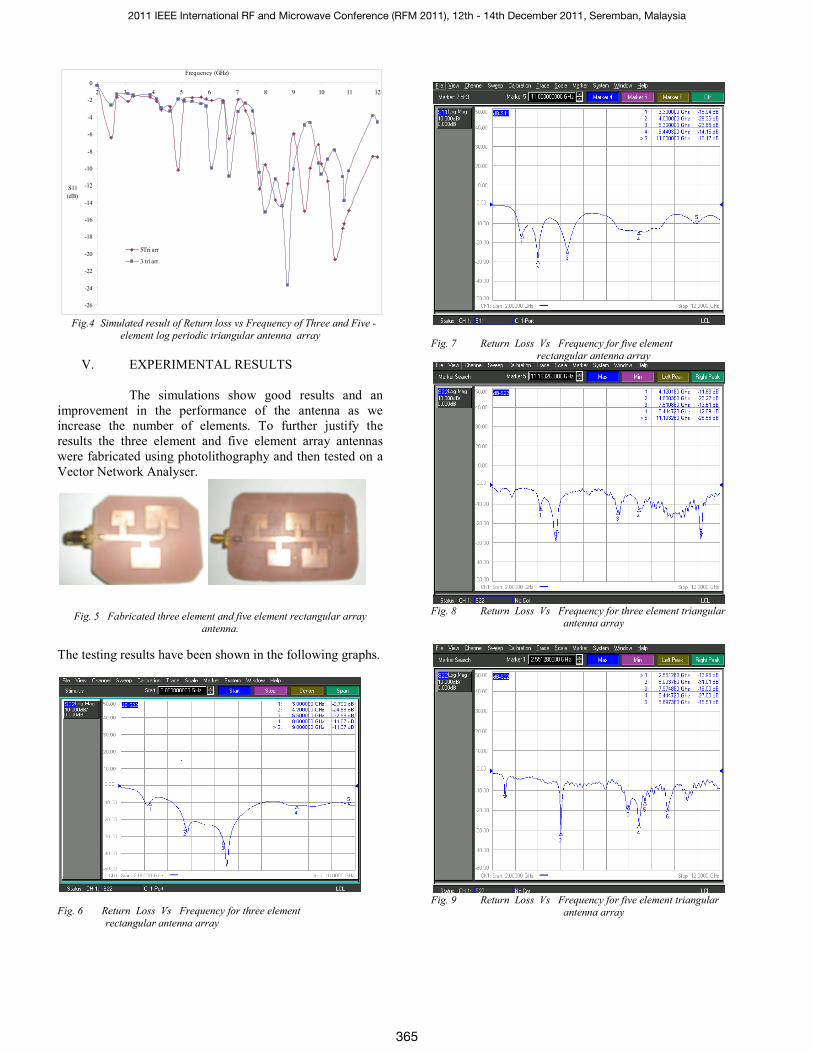
Fig.4 Simulated result of Return loss vs Frequency of Three and Five -
element log periodic triangular antenna array
V. EXPERIMENTAL RESULTS
The simulations show good results and an improvement in the performance of the antenna as we increase the number of elements. To further justify the results the three element and five element array antennas were fabricated using photolithography and then tested on a Vector Network Analyser.
Fig. 5 Fabricated three element and five element rectangular array
antenna.
The testing results have been shown in the following graphs.
Fig. 6 Return Loss Vs Frequency for three element rectangular antenna array
Fig. 7 Return Loss Vs Frequency for five element
rectangular antenna array
Fig. 8 Return Loss Vs Frequency for three element triangular
antenna array
Fig. 9 Return Loss Vs Frequency for five element triangular
antenna array
-26
-24
-22
-20
-18
-16
-14
-12
-10
-8
-6
-4
-2
02 3 4 5 6 7 8 9 10 11 12
5Tri arr
3 tri arr
Frequency (GHz)
S11 (dB)
2011 IEEE International RF and Microwave Conference (RFM 2011), 12th - 14th December 2011, Seremban, Malaysia
365

Fig.10 Experimental result of Return loss vs Frequency for Three and Five
- element log periodic rectangular antenna array
Fig. 11 Fabricated three element and five element triangular array antenna.
Fig.12 Experimental result of Return loss vs Frequency for Three and Five - element log periodic triangular antenna array
Fig.13 Simulated and Experimental result of Return loss vs Frequency for three - element log periodic rectangular and triangular antenna arrays
Fig.14 Simulated and Experimental result of Return loss vs Frequency for Five - element log periodic rectangular and triangular antenna arrays
TABLE 1
Comparative Table between three element and five element rectangular and triangular array
-60
-50
-40
-30
-20
-10
02 3 4 5 6 7 8 9 10 11 12
3 Rect
5 Rect
S11(dB)
Frequency(GHz)
-60
-50
-40
-30
-20
-10
02 3 4 5 6 7 8 9 10 11 12
S11 (3 ele tri)
S11 (5 ele tri)
Frequency (GHz)
S11 (dB)
-50
-45
-40
-35
-30
-25
-20
-15
-10
-5
02 3 4 5 6 7 8 9 10 11 12
Frequency(GHz)
S11(
dB)
Exp 3rect
Sim 3rect
Exp 3tri
Sim 3tri
-35
-30
-25
-20
-15
-10
-5
02 3 4 5 6 7 8 9 10 11 12
Frequency(GHz)
S11
(dB
)
Sim 5 rect Sim 5Tri Exp 5Tri Exp 5rect
2011 IEEE International RF and Microwave Conference (RFM 2011), 12th - 14th December 2011, Seremban, Malaysia
366

Results
Three element rectangular array
Five element rectangular array
Three element Triangular array
Five element Triangular array
Gain(dBi)
5.87
6.98
4.81
7.7
Freq(GHz)
4.944
5.44
7.86
8.37
Discussion of results: For three element array (Fig. 2) the antenna resonates at three frequencies (4.95 GHz, 6.2 GHz, and 8.2 GHz) and for five element antenna (Fig. 2) the resonances have increased to 5 points (4.95 GHz, 5.95 GHz, 7.88 GHz, 8.85 GHz and 9.8 GHz). The simulated results of triangular arrays(Fig. 4) shows resonance at five different frequencies(6.08GHz, 6.7GHz, 8GHz, 8.8GHz,10GHz,) for three element array and six frequencies(4.9GHz, 7.8GHz, 8.6FHz, 9.4GHZ, 10.49GHz,10.81GHz) for five element array. The experimental results also almost justify the simulated results; slight variation may be due to some fabrication errors. From the results it is understood that as we increase the number of elements in the antenna it shows frequency independent behavior and it can operate at more number of frequencies. From Table 1 it is clear that the maximum antenna gain is 5.87 dBi for three element and 6.98 dBi for five element rectangular patch antenna. The maximum antenna gain is 4.81 dBi for three element and 7.7 dBi for five element triangular patch antenna. This shows a considerable enhancement in gain of the antenna on increasing the number of elements. The experimental results show a good match with the simulated results and at some point they are better than the simulations. The range of operating frequency for three element and five element antenna is slightly different, i.e., it increases in some regions and decreases in some regions but still the increase in gain is very significant in five element triangular patch antenna.
CONCLUSION
It can be concluded that a high gain log periodic antenna using rectangular and triangular patches is designed and tested. It is clear that as we increased the number of patches the gain increased and also the antenna exhibits better frequency independent behavior. From the discussions and comparisons the log periodic antenna with five triangular patches exhibited the best results.
REFERENCES
[1] K. R. Carver and J. W. Mink, “ Microstrip antenna technology,” IEEE Trans. Antennas Propagation., vol. AP–29, pp. 2- 24, Jan.1981. [2] R. J. Mailloux, J. F. Mclenna, and N. P. Kernweis, “Microstrip array technology, “ IEEE Trans. Antennas Propagation., vol. AP-29, pp. 25- 37, Jan. 1981 [3] Mohamad Kamal A. Rahim, “Active Log Periodic Antenna”, Jurnal Teknologi, 46(D) Jun 2007, pp 17–34. [4] M. K. A. Rahim and P. Gardner, “Design of Nine Element Quasi Micro strip Log Periodic Antenna”, 2004 RF and Microwave Conference, October 5-6, Subang, Selangor, Malaysia, pp 132-135. [5] A. K. Gautam, “Antenna and Wave Propagation”, S.K. Kataria and Sons, 2010 Edition. [6] Ramesh Garg, “Microstrip Antenna Design Handbook”, Prakash Bhartia Publications, 2000 Edition. [7] Constantine A. Balanis, ”Antenna Theory Analysis and Design”, John Wiley & Sons, Inc., Second Edition.
2011 IEEE International RF and Microwave Conference (RFM 2011), 12th - 14th December 2011, Seremban, Malaysia
367