army tm 11-6625-2946-14 us marine corps tm …tm 11-6625-2946-14/tm 08168a-14/1 the following...
TRANSCRIPT

A R M Y T M 1 1 - 6 6 2 5 - 2 9 4 6 - 1 4
U S M A R I N E C O R P S T M 0 8 1 6 8 A - 1 4 / l
O P E R A T O R ’ S , O R G A N I Z A T I O N A L ,
D I R E C T S U P P O R T , A N D G E N E R A L S U P P O R T
M A I N T E N A N C E M A N U A L
T E S T S E T T S - 3 3 5 4 / P R C - 6 8
( N S N 6 6 2 5 - 0 1 - 0 9 1 - 3 1 5 7 )
D E P A R T M E N T S O F T H E A R M Y A N D T H E U S M A R I N E C O R P S
1 2 S E P T E M B E R 1 9 8 0


TM 11-6625-2946-14
TM 08166A-14/1
T ECHNICAL M A N U A L
No. 11-6625-2946-14 (Army)No. 08168A- 14/ 1 (Marine Corps) I
DEPARTMENTS OF THE ARMYAND THE US MARINE CORPS
WASHINGTON, DC 12 September 1980
O P E R A T O R ’ S , O R G A N I Z A T I O N A LDIRECT SUPPORT, AND GENERAL SUPPORT MAINTENANCE MANUAL
T E S T S E T T S - 3 3 5 4 / P R C - 6 8
( N S N 6 6 2 5 - 0 1 - 0 9 1 - 3 1 5 7 )
REPORTING ERRORS AND RECOMMENDING IMPROVEMENTSYou can help improve this manual. If you find any mistakes or if you know of a way to improve the procedures,
please let us know. Mail your letter, DA Form 2028 (Recommended Changes to Publications and Blank Forms), or DAForm 2028-2 located in back of this manual direct to Commander, US Army Communications and ElectronicsMateriel Readiness Command, ATTN: DRSEL-ME-MQ, Fort Monmouth, NJ 07703.
Marine Corps Units should submit NAVMC 10772.In either case, a reply will be furnished direct to you.
CHAPTER 1. INTRODUCTIONSECTION 1. General
Scope . . . . . . . . . . . . . . . . . . . . . . . . . . . . . . . . . . . . . . . . . . . . . . . . . . . . . . . . . . . . . . . . . . . . . . . . . .Indexes of publications . . . . . . . . . . . . . . . . . . . . . . . . . . . . . . . . . . . . . . . . . . . . . . .Maintenance forms, records, and reports . . . . . . . . . . . . . . . . . . . . . . . . . . . . . . . . . . . . .Destruction of Army Electronics Materiel . . . . . . . . . . . . . . . . . . . . . . . . . . . . . . . . . . . . . . . . . . . . . . . . . . . . . . . . . . . .Administrative storage . . . . . . . . . . . . . . . . . . . . . . . . . . . . . . . . . . . . . . . . . . . . . . . . . . . . .Reporting equipment improvement recommendations (EIR). . . . . . . . . . . . . . . . . . . . . . . . . . . . . . . .
SECTION II. Description and dataPurpose and use . . . . . . . . . . . . . . . . . . . . . . . . . . . . . . . . . . . . . . . . . . . . . . . . . . . . . . . . . . . . . . .Description . . . . . . . . . . . . . . . . . . . . . . . . . . . . . . . . . . . . . . . . . . . . . . . . . . . . . . . . . . . . . . . . . . . . .Tabulated data . . . . . . . . . . . . . . . . . . . . . . . . . . . . . . . . . . . . . . . . . . . . . . . . . . . . . . . . . . . . . . . . . . . . . . .
CHAPTER 2. OPERATING INSTRUCTIONSSECTION I. Service upon receipt of materiel
Unpacking . . . . . . . . . . . . . . . . . . . . . . . . . . . . . . . . . . . . . . . . . . . . . . . . . . . . . . . . . . . . . . . . . . . . . . . . .Checking unpacked equipment..... . . . . . . . . . . . . . . . . . . . . . . . . . . . . . . . . . . . . . . . . . . . . . . . . . . . . . . . . .
SECTION II. Controls and indicatorsGeneral . . . . . . . . . . . . . . . . . . . . . . . . . . . . . . . . . . . . . . . . . . . . . . . . . . . . . . . . . . . . . . . . . . . . . . . . . . .Operator Controls . . . . . . . . . . . . . . . . . . . . . . . . . . . . . . . . . . .
SECTION III. Operating proceduresPreliminary starting procedure... . . . . . . . . . . . . . . . . . . . .Field operation (14 V battery) . . . . . . . . . . . . . . . . . . . . . . . . . . . . . . . . . . . . . . . . . . . . . . . . . . .operating from 24V external power supply . . . . . . . . . . . . . . . . . . . . . . . . . . . . . . . . . . . . . . . . . . . . . . . . . . . . . .
CHAPTER 3. OPERATOR/ORGANIZATIONAL MAINTENANCE INSTRUCTIONSSECTION 1. Tools and equipment
Common tools and equipment . . . . . . . . . . . . . . . . . . . . . . . . . . . . . . . . . . . . . . . . . . . . . . . . . . . . . . . . .Special tools and equipment . . . . . . . . . . . . . . . . . . . . . . . . . . . . . . . . . . . .Materials required............... . . . . . . . . . . . . . . . . . . . . . . . . . . . . . . . . . . . . . . . . . . . . . . . . . . . . . . . . . . . . . . .
SECTION 11. Preventive maintenance checks and serviceGeneral . . . . . . . . . . . . . . . . . . . . . . . . . . . . . . . . . . . . . . . . . . . . . . . . . . . . . . . . . . . . . . . . . . . . . . . . . . . .
Paragraph Page
l - l1-21-31-41-5I -6
1-71-81-9
2-12-2
2-32-4
2-52-62-7
3-l3-23-3
3-4
1-11-11-11-11-11-1
1-11-11-1
2-12-1
2-12-1
2-32-32-3
3-13-13-1
3-1
I

TM 11-6625-2946-14/TM 08168A-14/1
Paragraph PageScope of operator/organizational preventive maintenance . . . . . . . . . . . . . . . . . . . . . . . . . . . . . . . . . . . . . . . . . . . . . .Removal . . . . . . . . . . . . . . . . . . . . . . . . . . . . . . . . . . . . . . . . . . . . . . . . . . . . . . . . . . . . . . . . . . . . . . . . . . . . . . . . . . . . . . . .Cleaning . . . . . . . . . . . . . . . . . . . . . . . . . . . . . . . . . . . . . . . . . . . . . . . . . . . . . . . . . . . . . . . . . . . . . . . . . . . . . . . . . . . . . . . .
SECTION III. TroubleshootingTroubleshooting . . . . . . . . . . . . . . . . . . . . . . . . . . . . . . . . . . . . . . . . . . . . . . . ... . .. ... ......
CHAPTER 4. FUNCTIONING OF EQUIPMENT. . . . . . . . ., .,...
General . . . . . . . . . . . . . . . . . . . . . . . . . . . . . . . . . . . . . . . . . . . . . . . . . . . . . . . . . . . . . . . . . . . . . . . . . . . . . . . . . . . . . . . . .Power input . . . . . . . . . . . . . . . . . . . . . . . . . . . . . . . . . . . . . . . . . . . . . . . . . . . . . . . . . . . . . . . . . . . . . . . . . . . . . . . . . . . .Battery test mode . . . . . . . . . . . . . . . . . . . . . . . . . . . . . . . . . . . . . . . . . . . . . . . . . . . . . . . . . . . . . . . . . . . . . . . . . . . . . . . .Transmitter rf power out put test mode . . . . . . . . . . . . . . . . . . . . . . . . . . . . . . . . . . . . . . . . . . . . . . . . . . . . . . . . . . . . . . .Receiver sensitivity test mode . . . . . . . . . . . . . . . . . . . . . . . . . . . . . . . . . . . . . . . . . . . . . . . . . . . . . . . . . . . . . . . . . . . . . . .Field strength measurement mode.. . . . . . . . . . . . . . . . . . . . . . . . . . . . . . . . . . . . . . . . . . . . . . . . . . . . . . . . . . . . . . . ..
CHAPTER 5. GENERAL SUPPORT MAINTENANCESECTION 1. General
Scope . . . . . . . . . . . . . . . . . . . . . . . . . . . . . . . . . . . . . . . . . . . . . . . . . . . . . . . . . . . . . . . . . . . . . . . . . . . . . . . . . . . . . . . . . .Tools and equipment . . .... ........ . . . . . . . . . . . . . . . . . . . . . . . . . . . . . . . . . . . . . . . . . . . . . . . . . . . . . . . . . . . . . . . .
SECTION 11. TroubleshootingGeneral . . . . . . . . . . . . . . . . . . . . . . . . . . . . . . . . . . . . . . . . . . . . . . . . . . . . . . . . . . . . . . . . . . . . . . . . . . . . . . . . . . . . . . . . .Fault isolation procedures, . . . . . . . . . . . . . . . . . . . . . . . . . . . . . . . . . . . . . . . . . . . . . . . . . . . . . . . . . . . . . . . . . . . . . . . .
SECTION III. MaintenanceGeneral . . . . . . . . . . . . . . . . . . . . . . . . . . . . . . . . . . . . . . . . . . . . . . . . . . . . . . . . . . . . . . . . . . . . . . . . . . . . . . . . . . . . . . . . .Alignment . . . . . . . . . . . . . . . . . . . . . . . . . . . . . . . . . . . . . . . . . . . . . . . . . . . . . . . . . . . . . . . . . . . . . . . . . . . . . . . . . . . . . .
SECTION IV. Performance testsGeneral . . . . . . . . . . . . . . . . . . . . . . . . . . . . . . . . . . . . . . . . . . . . . . . . . . . . . . . . . . . . . . . . . . . . . . . . . . . . . . . . . . . . . . . . .Power input circuit performance test, . . . . . . . . . . . . . . . . . . . . . . . . . . . . . . . . . . . . . . . . . . . . . . . . . . . . . . . . . . . . . . .Rf power detection and metering circuit performance test (with power amplifier) . . . . . . . . . . . . . . . . . . . . . . . . . . .Rf power detection and metering circuit performance test (without power amplifier) ., . . . . . . . . . . . . . . . . . . . . . . .
SECTION IV. Rf signal generator output frequency and level performance test . . . . . . . . . . . . . . . . . . . . . . . . . . . . . . . . . . . . . . . . .Receiver sensitivity measuring circuit performance test . . . . . . . . . . . . . . . . . . . . . . . . . . . . . . . . . . . . . . . . . . . . .Field strength measurement circuit performance test . . . . . . . . . . . . . . . . . . . . . . . . . . . . . . . . . . . . . . . . . . . . . . . . . . .
APPENDIX A. REFERENCES . . . . . . . . . . . . . . . . . . . . . . . . . . . . . . . . . . . . . . . . . . . . . . . . . . . . . . . . . . . . . . . . . . . . . . . . . . . . . . . . . . . .
3-53-63-7
3-8
4-14-24-34-44-54-6
5-15-2
5-35-4
5-55-6
5-75-85-95-105-115-125-13
B. MAINTENANCE ALLOCATION, . . . . . . . . . . . . . . . . . . . . . . . . . . . . . . . . . . . . . . . . . . . . . . . . . . . . . . . . . . . . . . . . . . . . . . . . .. . . . . .
C. COMPONENTS OF END ITEM ..... . . . . . . . . . . . . . . . . . . . . . . . . . . . . . . . . . . . . . . . . . . . . . . . . . . . . . . . . . . . . . . . . . . . . . . . . .C-1D. ADDITIONAL AUTHORIZATION LIST (Not applicable)E. EXPENDABLE SUPPLIES AND MATERIALS LIST.. . . . . . . . . . . . . . . . . . . . . . . . . . . . . . . . . . . . . . . . . , . . . . . . . . . . . . . . . . .. E-1
3-13-23-2
3-2
4-14-14-14-14-14-3
5- 15-1
5-15-1
5-45-4
5-125-125-125-125-135-145-14A- 1B-1
Figure No1-12-14-15-15-25-35-45-4A5-55-65-7c-1F0-1
Table No.2-13-15-15-2
II
LIST OF ILLUSTRATIONSTitle Page
Test Set TS-3354/PRC-68 . . . . . . . . . . . . . . . . . . . . . . . . . . . . . . . . . . . . . . . . . . . . . . . . . . . . . . . . . . . . . . . . . . . . . . . . . . . . . . . . 1-0Test set operating controls, indicators and connectors . . . . . . . . . . . . . . . . . . . . . . . . . . . . . . . . . . . . . . . . . . . . . . . . . . . . . . . . . 2-1Test set block diagram...........,.. . . . . . . . . . . . . . . . . . . . . . . . . . . . . . . . . . . . . . . . . . . . . . . . . . . . . . . . . . . . . . . . . . . . . . . 4-2Component and test point locations. . . . . . . . . . . . . . . . . . . . . . . . . . . . . . . . . . . . . . . . . . . . . . . . . . . . . . . . . . . . . . . . . . . . . . . 5-2Test point locations and waveform legend . . . . . . . . . . . . . . . . . . . . . . . . . . . . . . . . . . . . . . . . . . . . . . . . . . . . . . . . . . . . . . . . . . . 5-5Attenuator alignment test set up . . . . . . . . . . . . . . . . . . . . . . . . . . . . . . . . . . . . .............................. . . . . . . . . . . 5-7Rf power detection and metering circuit test set up (with power amplifier) . . . . . . . . . . . . . . . . . . . . . . . . . . . . . . . . . . . . . . . . . 5-8Rf power detection and metering circuit test setup (without power amplifier) . . . . . . . . . . . . . . . . . . . . . . . . . . . . . . . . . . . . 5-9AN/PRC-68 switch location (sheets 1 and 2) . . . . . . . . . . . . . . . . . . . . . . . . . . . . . . . . . . . . . . . . . . . . . . . . . . . . . . . . . . . . . . . . . 5-10Rf signal generator output frequency and level test setup . . . . . . . . . . . . . . . . . . . . . . . . . . . . . . . . . . . . . . . . . . . . . . . . . . . . . . . 5-15Receiver sensitivity measuring circuit test setup . . . . . . . . . . . . . . . . . . . . . . . . . . . . . . . . . . . . . . . . . . . . . . . . . . . . . . . . . . . . . . . 5-16Components of end item layout . . . . . . . . . . . . . . . . . . . . . . . . . . . . . . . . . . . . . . . . . . . . . . . . . . . . . . . . . . . . . . . . . . ...... .... C-3Test Set TS-3354/PRC-68, schematic diagram (sheets 1 through 6) . . . . . . . . . . . . . . . . . . . . . . . . . . . . . . . . . . . . . . . . . . . . . . . Located in
back ofmanual
LIST OF TABLESTitle Page
Operating Controls, Indicators, and Connectors. . . . . . . . . . . . . . . . . . . . . . . . . . . . . . . . . . . . . . . . . . . . . . . . . . . . . . . . . . . . . . 2-2Operator/Organizational Preventive Maintenance Checks and Services . .. .. . . . . . . . . . . . . . . . . . . . . . . . . . . . . . . . . . . . . 3-1Fault Isolation Chart . . . . . . . . . . . . . . . . . . . . . . . . . . . . . . . . . . . . . . . . . . . . . . . . . . . . . . . . . . . . . . . . . . . . . . . . . . . . . . . . . . . . . 5-3Test Set Alignment Procedure . . . . . . . . . . . . . . . . . . . . . . . . . . . . . . . . . . . . . . . . . . . . . . . . . . . . . . . . . . . . . . . . . . . . . . . . . . . . . 5-4
TM 11-6625-2946-14/TM 08168A-14/1
Page5-3 Power input Circuit Performance Test . . . . . . . . . . . . . . . . . . . . . . . . . . . . . . . . . . . . . . . . . . . . . . . . . . . . . . . . . . . . . . . . . . . . . . s-125-4 RF Power Detection and Metering Circuit Performance Test (with Power Amplifier) . . . . . . . . . . . . . . . . . . . . . . . . . . . . . . . 5-135-4A RF Power Detection and Metering Circuit Performance Test (without Power Amplifier) . . . . . . . . . . . . . . . . . . . . . . . . . . . . 5-135-5 RF Signal Generator Output Frequency and Level Performance Tests . . . . . . . . . . . . . . . . . . . . . . . . . . . . . . . . . . . . . . . . . . . . 5-135-6 Receiver sensitivity Measuring Circuit Performance Test . . . . . . . . . . . . . . . . . . . . . . . . . . . . . . . . . . . . . . . . . . . . . . . . . . . . . . 5-145-7 Field Strength Measurement Circuit Performance Test . . . . . . . . . . . . . . . . . . . . . . . . . . . . . . . . . . . . . . . . . . . . . . . . . . . . . . . . 5-17
III

TM 11-6625-2946-14/TM 08168A-14/1
Figure 1-1. Test Set TS-3354/PRC-68
1 - 0

TM 11-6625-2946-14/TM 08168A-14/1
C H A P T E R 1
I N T R O D U C T I O N
Section 1. GENERAL
1-1 . Scope
This manual contains operating and maintenance in-structions for Test Set TS-3354/PRC-68 (fig. 1-1 ) at theOperator (Echelon 1 Maintenance), Organizational(Echelon 2 Maintenance), and General Support (Eche-lon 4 Maintenance) levels. Direct Support maintenanceis not authorized.
1 -2 . Indexes o f Pub l i ca t ions
a. DA Pam 310-4. Refer to latest issue of DA Pam310-4 to determine whether there are new editions,changes, or additional publications pertaining to theequipment.
b. DA Pam 310-7. Refer to DA Pam 310-7 to deter-mine whether there are modification work orders(MWO’S) pertaining to the equipment.
1 - 3 . M a i n t e n a n c e F o r m s , R e c o r d s a n dR e p o r t s
a. Reports of Maintenance and Unsatisfactory Equip-ment. Maintenance forms, records, and reports whichare to be used by maintenance personnel at allmaintenance levels are listed in and prescribed by TM38-750, the Army Maintenance Management System.Marine Corps should refer to current edition of TM4700-15/1.
b. Report of Item and Packaging Discrepancies.Fill out and forward SF 364 (Report of Discrepancy(ROD)) as prescribed in AR 735-11-2/NAVSUPINST4440.127E/AFR 400.54/MCO 4430E and DSAR4140.55.
c. Discrepancy in Shipment Report (DISREP) (SF361). Fill out forward Discrepancy in Shipment Report(DISREP) (SF 361) as prescribed in AR 55-38/NAVSUPINST 4610.33 B/AFR 75-18/MCO P4610.19Cand DLAR 4500.15.
1 - 4 . D e s t r u c t i o n o f A r m y E l e c t r o n i c sM a t e r i e l .
Destruction of Army electronics materiel to preventenemy use shall be in accordance with TM 750-244-2.
1 -5 . Admin is t ra t i ve S to rage
Administrative storage of equipment issued to and usedby Army activities will have preventive maintenance per-formed in accordance with the PMCS charts before stor-ing. When removing the equipment from administrativestorage, the PMCS should be performed to assure opera-tional readiness. Disassembly and repacking of equip-ment for shipment or limited storage are covered inparagraphs 3-4 and 3-5.
1 - 6 . R e p o r t i n g E q u i p m e n t I m p r o v e m e n tRecommendat ions (E IR)
If your Test Set TS-3354/PRC-68 needs improvement,let us know. Send us an EIR. You, the user, are the onlyone who can tell us what you don’t like about yourequipment. Let us know why you don’t like the design.Tell us why a procedure is hard to perform. Put it on anSF 368 (Quality Deficiency Report). Mail it to Com-mander, US Army Communications and ElectronicsMateriel Readiness Command, ATTN: DRSEL-ME-MQ, Fort Monmouth, NJ 07703. We’ll send you a reply.
Sec t ion I l . DESCRIPTION AND DATA
1-7. Purpose and Use set and the radio set. TheThe Test Set TS-3354/PRC-68 (test set), is a portableauxiliary test set used primarily for in-the-fieldmaintenance of Radio Set AN/PRC-68. The test set pro-vides capability for the measurement of the radio set bat-tery condition, receiver sensitivity, and transmitterpower output without the need for additional commonor special test equipment items. When operated in theportable or field mode, the battery of the radio set undertest provides the + 14 vdc input power for both the test
test set may also be operatedfrom an external +24 vdc source, which it reduces to a+ 14 vdc regulated level to provide power for both itselfand the radio set under test.
1 -8 . Descr ip t ion
The test set is mounted in a waterproof, removablecover, portable fiberglass case. The input circuit breakerand all operating controls, input and output connectors,and indicators, are located on the test set front panel.
1-1
TM 11-6625-2946-14/TM 08168A-14/1
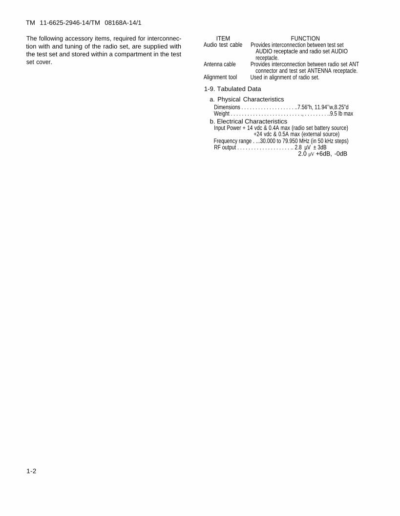
The following accessory items, required for interconnec- ITEMtion with and tuning of the radio set, are suppIied with Audio test cable
the test set and stored within a compartment in the testset cover. Antenna cable
Alignment tool
FUNCTIONProvides interconnection between test set
AUDIO receptacle and radio set AUDIOreceptacle.
Provides interconnection between radio set ANTconnector and test set ANTENNA receptacle.
Used in alignment of radio set.
1-9. Tabulated Data
a. Physical CharacteristicsDimensions . . . . . . . . . . . . . . . . . . . ..7.56”h, 11.94’’w,8.25”dWeight . . . . . . . . . . . . . . . . . . . . . . . . . ., . . . . . . . . ..9.5 lb max
b. Electrical CharacteristicsInput Power + 14 vdc & 0.4A max (radio set battery source)
+24 vdc & 0.5A max (external source)Frequency range . ...30.000 to 79.950 MHz (in 50 kHz steps)RF output . . . . . . . . . . . . . . . . . . . .. 2.8 µV ± 3dB
2.0 µV +6dB, -0dB
1-2

TM 11-6625-2946-14/TM 08168A-14/1
C H A P T E R 2
O P E R A T I N G I N S T R U C T I O N S
Section I . SERVICE UPON RECEIPT OF MATERIEL
2-1 . Unpack ing
2-2 . Check ing Unpacked Equ ipment
a. Inspect the test set for damage incurred during ship-ment. If the equipment has been damaged, report thedamage on SF 364 (Para 1-3 b).
b. Check the equipment against the components listedin Appendix C and the packing slip to see if the shipmentis complete. Report all discrepancies in accordance with
the instructions of TM 38-750. The equipment should beplaced in service, even though a minor assembly or partthat does not affect proper functioning is missing.
c. Check to see if the equipment has been modified.(Equipment which has been modified will have theMWO number on the front panel, near the nomen-clature plate.) Check also to see whether all currently ap-plicable MWO’S have been applied. (Current MWO’Sapplicable to the equipment are listed in DA Pam310-7.) Marines should refer to SL1 -2.
S e c t i o n i i . C O N T R O L S A N D i n d i c a t o r s
2 -3 . Genera l 2 -4 . Opera to r Con t ro ls
Haphazard operation, or improper control settings All operating controls, indicators, and input and outputcould damage equipment. It is, therefore, essential that connectors, as listed and functionally described in tableall operating controls and indicators be fully understood 2-1, are located on the test set front panel (fig. 2-l).before placing the test set in use.
Table 2-1. Operating Controls, Indicators, and Connectors
Control, indicator,or connector
POWER switch
RESET switchFUNCTION switch
FREQUENCY CODE switches
SENS READ pushbuttonswitch
Meter
FSM ANTENNABATTERY connectors
RADIO connectors
24 VDC EXT connectorAUDIO connectorANTENNA connector
Selects 14 vdc battery (BAT) or 24 vdc external (EXT) power source. Removes input power in center (OFF)position.
Spring-loaded circuit breaker. Resets in up position.selects test mode:
FSM rf field strength measurementRCV receiver sensitivity measurementXMT transmitter rf output power measurementBAT battery condition test
Selects desired rf output frequency of test set signal generator, corresponding to frequency of radio set beingtested .
Initiates measurement of receiver quieting over a preset 14 dB noise level to provide indication of receiver gainon the meter.
Provides a go (green)/no-go (red) reading to indicate status of battery or radio set under test in BAT, XMT,or RCV test modes. Provides measurement of rf signal detected by FSM ANTENNA in FSM mode.
Antenna for reception of radiated rf output of transmitter for measurement of its field strength.Polarized, pressure-lock type connectors for input from battery under test, secure battery to test set front
panel.Polarized, pressure-lock type connectors to provide input power to radio set under test, secure radio set to test
set front panel.For test set 24 vdc input voltage from external power source.Input connector for receiver audio from radio set AUDIO connector.Input connector for radio set transmitter rf output.
2-1

TM 11-6625-2946-14/TM 08168A-14/1
NOTE : RIGHT HALF OF METER SCALE IS GREEN AND LEFT HALF IS RED.
Figure 2-1. Test set operating controls, indicators and connectors.
2-2
TM 11-6625-2946-14/TM 08168A-14/1
Sec t ion I l l . OPERATING PROCEDURES
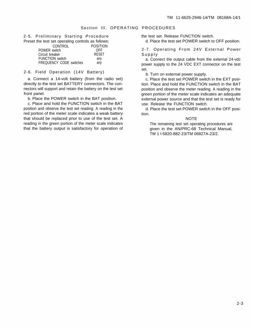
2-5 . Pre l im inary S ta r t ing Procedure the test set. Release FUNCTION switch.Preset the test set operating controls as follows: d. Place the test set POWER switch to OFF position.
CONTROL POSITIONPOWER switch OFF 2-7 . Opera t ing From 24V Ex te rna l PowerCircuit breaker RESET S u p p l yFUNCTION switch any a. Connect the output cable from the external 24-vdcFREQUENCY CODE switches any power supply to the 24 VDC EXT connector on the test
2-6. Field Operat ion (14V Battery)
a. Connect a 14-volt battery (from the radio set)directly to the test set BATTERY connectors. The con-nectors will support and retain the battery on the test setfront panel.
b. Place the POWER switch in the BAT position.c. Place and hold the FUNCTION swtich in the BAT
position and observe the test set reading. A reading in thered portion of the meter scale indicates a weak batterythat should be replaced prior to use of the test set. Areading in the green portion of the meter scale indicatesthat the battery output is satisfactory for operation of
set.b. Turn on external power supply.c. Place the test set POWER switch in the EXT posi-
tion. Place and hold the FUNCTION switch in the BATposition and observe the meter reading. A reading in thegreen portion of the meter scale indicates an adequateexternal power source and that the test set is ready foruse. Release the FUNCTION switch.
d. Place the test set POWER switch in the OFF posi-tion.
NOTEThe remaining test set operating procedures aregiven in the AN/PRC-68 Technical Manual,TM 1 l-5820-882-23/TM 06827A-23/2.
2-3


TM 11-6625-2946-14/TM 08168A-14/1
C H A P T E R 3
O P E R A T O R / O R G A N I Z A T I O N A L M A I N T E N A N C E I N S T R U C T I O N S
Sect ion 1. TOOLS AND EQUIPMENT
3-1 . Common Too ls and Equ ipment the operator and organizational maintenance of the test
Common tools and test equipment items required for set.
operator and organizational maintenance of the test set 3 -3 . Mate r ia l s Requ i redare listed in the maintenance allocation chart, appendixD. Equivalent test equipment items may be substituted The following materials are required for operator/or-
as necessary. ganizational maintenancea. Lint-free cleaning cloth
3-2 . Spec ia l Too ls and Equ ipment b. Trichlorotrifluroethane
No special tools or test equipment items are required for c. Soft-bristled brush.
Sec t ion I l . PREVENTIVE MAINTENANCE CHECKS AND SERVICES
3-4. General
To ensure that the test set is always ready for operation,it must be inspected systematically so that defects maybediscovered and corrected before they result in seriousdamage or failure. The necessary preventive main-tenance checks and services (PMCS) to be performed arelisted and described in table 3-1. The item numbers in-dicate the sequence of the minimum inspection require-ments. Defects discovered during operation of the unitwill be noted for corrective action as soon as operationhas ceased. If a deficiency is noted that will result indamage to the equipment, stop operation immediately.Record all deficiencies together with the corrective ac-tion taken as prescribed in TM 38-750. Marine Corpspersonnel will refer to current addition of TM4700-15/1.
3 - 5 . S c o p e o f O p e r a t o r / O r g a n i z a t i o n a lPreven t i ve Ma in tenance
a. General.
(1) Preventive maintenance is the systematic inspec-tion, care, and servicing of the test set to insure its com-pleteness, serviceability, and immediate availability andcapability for the testing of Radio Set AN/PRC-68.
(2) Since operation of the test set will be performedby maintenance personnel at the organizational level,operator and organizational preventive maintenancechecks and services are combined into a single procedure(table 3-1 ).
b. PMCS Scheduling. Preventive maintenance checksfor the test set are required on a before-operation, week-ly, monthly, and quarterly basis. In addition to thesescheduled intervals, the before-operation and weeklychecks should be performed under the following specialconditions:
(1) Receipt of equipment.(2) Return from higher category maintenance.(3) Monthly, if the equipment is maintained in
standby condition.
Table 3-I. Operator/OrganizationalPreventive Maintenance Checks and Services
Itemno.1
2
3
B—Before W—Weekly M—Monthly
Item to be inspected procedureCOMPLETENESS
Check to ensure that equipment, including accessory items,is complete. Refer to figure 1-1 and appendix B.
EXTERIOR SURFACEInspect exterior surfaces, with cover removed, for dust,
moisture, and corrosion. Clean as necessary (paras. 3-6 and3-7).
CONTROLS AND INDICATORSCheck for missing, broken, or loose control knobs.Check the mechanical action of each control for binding or
excessive looseness. Check the meter for a bent or stickingneedle.
Q—Quarterly
Equipment will be reported not ready if:
Any item is missing and replacement item is not immediatelyavailable.
Operation of the test set is impaired by faulty or intermittentcontrol functions or inoperative or inaccurate meter.
3-1
TM 11-6625-2946-14/TM 08168A-14/1
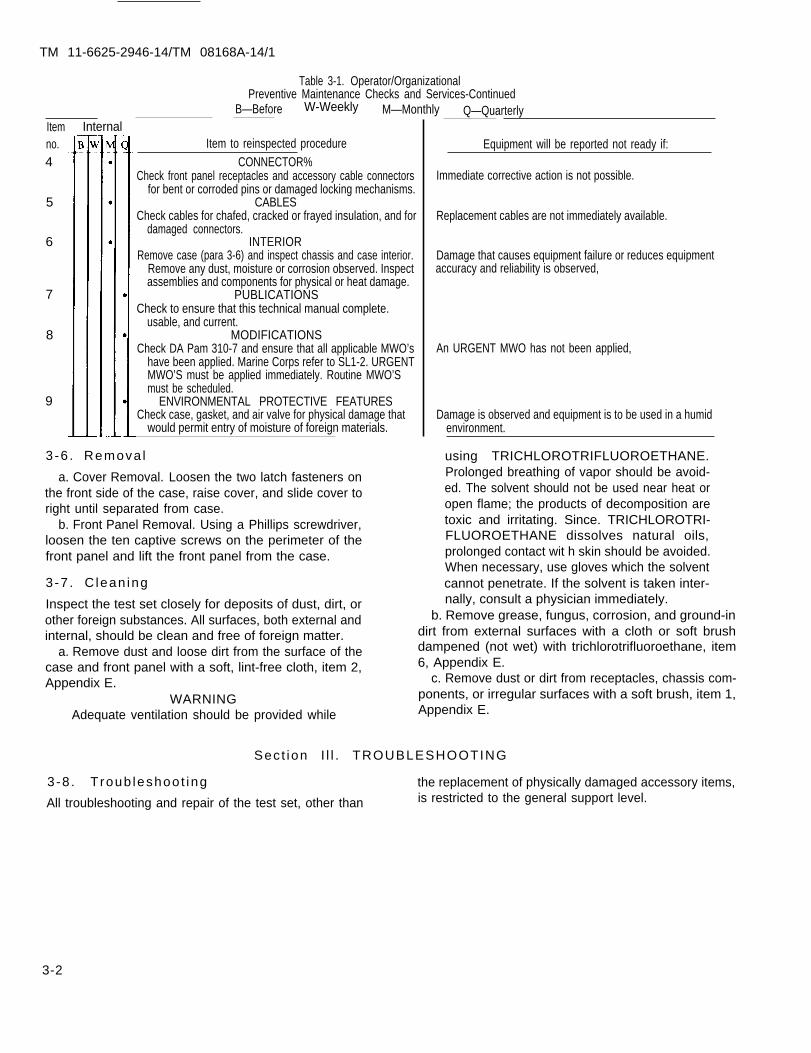
Table 3-1. Operator/Organizational Preventive Maintenance Checks and Services-Continued
B—Before W-Weekly M—Monthly Q—QuarterlyItemno.4
5
6
7
8
9
Item to reinspected procedureCONNECTOR%
Check front panel receptacles and accessory cable connectorsfor bent or corroded pins or damaged locking mechanisms.
CABLESCheck cables for chafed, cracked or frayed insulation, and for
damaged connectors.INTERIOR
Remove case (para 3-6) and inspect chassis and case interior.Remove any dust, moisture or corrosion observed. Inspectassemblies and components for physical or heat damage.
PUBLICATIONSCheck to ensure that this technical manual complete.
usable, and current.MODIFICATIONS
Check DA Pam 310-7 and ensure that all applicable MWO’shave been applied. Marine Corps refer to SL1-2. URGENTMWO’S must be applied immediately. Routine MWO’Smust be scheduled.
ENVIRONMENTAL PROTECTIVE FEATURESCheck case, gasket, and air valve for physical damage that
would permit entry of moisture of foreign materials.
3 -6 . Remova l
a. Cover Removal. Loosen the two latch fasteners onthe front side of the case, raise cover, and slide cover toright until separated from case.
b. Front Panel Removal. Using a Phillips screwdriver,loosen the ten captive screws on the perimeter of thefront panel and lift the front panel from the case.
3 -7 . C lean ing
Inspect the test set closely for deposits of dust, dirt, orother foreign substances. All surfaces, both external and
Equipment will be reported not ready if:
Immediate corrective action is not possible.
Replacement cables are not immediately available.
Damage that causes equipment failure or reduces equipmentaccuracy and reliability is observed,
An URGENT MWO has not been applied,
Damage is observed and equipment is to be used in a humidenvironment.
using TRICHLOROTRIFLUOROETHANE.Prolonged breathing of vapor should be avoid-ed. The solvent should not be used near heat oropen flame; the products of decomposition aretoxic and irritating. Since. TRICHLOROTRI-FLUOROETHANE dissolves natural oils,prolonged contact wit h skin should be avoided.When necessary, use gloves which the solventcannot penetrate. If the solvent is taken inter-nally, consult a physician immediately.
b. Remove grease, fungus, corrosion, and ground-in
internal, should be clean and free of foreign matter. dirt from external surfaces with a cloth or soft brush
a. Remove dust and loose dirt from the surface of the dampened (not wet) with trichlorotrifluoroethane, item
case and front panel with a soft, lint-free cloth, item 2, 6, Appendix E.
Appendix E. c. Remove dust or dirt from receptacles, chassis com-
WARNING ponents, or irregular surfaces with a soft brush, item 1,
Adequate ventilation should be provided while Appendix E.
Sec t ion I l l . TROUBLESHOOTING
the replacement of physically damaged accessory items,is restricted to the general support level.
3 -8 . T roub leshoo t ing
All troubleshooting and repair of the test set, other than
3-2
Internal

TM 11-6625-2946-14/TM 08168A-14/1
C H A P T E R 4
F U N C T I O N I N G O F E Q U I P M E N T
4-1 . Genera l
The test set employs three basic circuits (fig. 4-l); asignal generator, a field strength detector, and a meter-ing circuit. The circuits function to provide the fourmodes of operation required for operational testing ofthe radio set at the Operator’s/Organizational mainte-nance level and isolation of faults to a module at theGeneral Support maintenance level. The four modes ofoperation are:
a. Battery testb. Transmitter rf power output testc. Receiver sensitivity testd. RF field strength measurement.
4-2. Power Input
The test set receives its power from a 14-vdc battery or anexternal 24-vdc source. When the battery is used, its con-nectors are mated directly with the BATTERY connec-tors on the test set front panel. When the POWER switchis placed in the BAT position, the battery voltage is fedthrough the circuit breaker to the test set functional cir-cuitry. When a 24-vdc external source is used it is con-nected to the 24 VDC EXT connector on the test setfront panel. When the POWER switch is placed in theEXT position, the 24 VDC EXT input from the externalpower source is fed to a voltage regulator where it isdropped to a 14-vdc level. The 14-vdc regulated voltageis then fed through the circuit breaker to the test set func-tional circuitry. In the transmitter rf output (XMT) andreceiver sensitivity y (RCV) test modes, the 14-vdc outputof the circuit breaker provides input power to the radioset under test, through the RADIO output connectors onthe test set front panel.
4-3. Battery Test Mode
In the battery test mode, the battery is connected directlyto the BATTERY input connector on the test set frontpanel. The battery current is routed through thePOWER switch (BAT position), the circuit breaker, theFUNCTION switch (BAT position), the battery test cir-cuit, and the meter (dc ammeter) to ground, to providemeasurement of the battery voltage across a 44.2-ohmload. The battery test circuit is calibrated to provide amidscale reading for a battery input level of 12 vdc and 1volt-per-division, up to a full scale reading of 17 vdc, onthe upper (green) scale. Since the end of battery life is 12vdc, the meter provides a simple go (green) or no-go (red)reading to indicate the battery’s serviceability status.
4 - 4 . T r a n s m i t t e r R F P o w e r O u t p u t T e s tM o d e
In the transmitter rf power output (XMT) test mode, theradio set rf output is connected to the test set ANTEN-NA connector. When the radio set is keyed, the test set rfinput is attenuated 6 dB through a 50-ohm pad, thendetected to a dc current level by the rf attenuator anddetector assembly. The detected dc current is then fedthrough the rf power metering circuit to the meter. Themeter zero is calibrated for a midscale deflection of 0.5watt transmitter rf output by the rf power metering cir-cuit; thus, transmitter output exceeding 0.5 watt willprovide a reading in the green portion of the meter scale,indicating adequate power output on the frequencyselected on the radio set. Transmitter power output canbe measured at any radio set channel frequency.
4-5. Receiver Sensit iv i ty Test Mode
a. In the receiver sensitivity (RCV) test mode, themeasurement of receiver sensitivity is attained by thecomparison of the noise level of the audio input (atAUDIO connector) from the AN/PRC-68 receiver beingtested, with no rf input from the test set, and the level ofreceiver quieting resulting from an rf input of 2.0 + 6dB, – 0 dB microvolt (ANTENNA connector). Withthe pushbutton SENS switch in the normal position, noB + is applied to the rf signal generator; therefore no rfinput is applied to the receiver. The volume control onthe receiver is adjusted to set the noise level for amidscale reading on the test set meter. When the SENSREAD switch is pressed, the rf signal is applied to thereceiver (at ANTENNA connector) and the resultantaudio quieting level output is indicated on the meter. Areading in the upper (green) portion of the meter scale in-dicates satisfactory receiver sensitivity y.
b. When the SENS READ switch is pressed, the rfsignal generator circuitry generates a 30.000 to 79.950MHz, rf output signal selectable in 50-kHz steps. Thedesired frequency, corresponding to that selected on theAN/PRC-68 under test, is selected with the four fre-quency control switches on the test set. When the SENSREAD pushbutton is pressed, the synthesizer generates afrequency reference voltage to drive the voltage con-trolled oscillator for the generation of a 42 to 68 MHzreference signal, 12 MHz above (for 30 to 54 MHz) orbelow (for 54 thru 80 MHz) the selected frequency. Thereference signal is amplified then combined, in a balanc-ed mixer, with the output of a 12-MHz stable oscillatorto provide a resultant rf output at the selected frequency.
4-1

TM
11-6625-2946-14/T
M
08168A-14/1
4-
2
Fig
ure
4
-1.
Te
st se
t b
lock
dia
gra
m

TM 11-6625-2946-14/TM 08168A-14/1
The mixer output is then attenuated to provide the rfoutput to the radio set receiver at the ANTENNA con-nector.
4 -6 . F ie ld S t reng th Measurement Mode
The field strength measurement (FSM) mode providesmeasurement of the radio set radiated power formonitoring its output in the adjustment of the radio setantenna coupler. The radiated rf signal is received by thetest set antenna and converted to a dc level by the fieldstrength detector circuit. The detected dc current causes
meter deflection corresponding to the rf power levelreceived; therefore, in the use of the FSM, the red andgreen portions of the meter scale are not significant. Inthe use of the FSM for coupler adjustment, the ad-justments are made for maximum deflection on themeter. To avoid effects from the meter-protectionlimiter of the field strength measurement circuit andfrom signals radiated from the radio set internal cir-cuitry, the FSM should be operated at a meter readinglevel of 7 units or less by increasing the distance betweenthe test set and the radio antenna.
4-3


TM 11-6625-2946-14/TM 08168A-14/1
C H A P T E R 5
G E N E R A L S U P P O R T M A I N T E N A N C E
NOTENo Direct Support maintenance of the test set organizational repair shops and forward themis authorized. Direct Support maintenance ac- to the applicable General Support maintenancetivities will receive defective test sets from activity for maintenance.
Section L GENERAL
5-1. Scope. 5-2. Tools and Equipment
This chapter contains the troubleshooting, performance The tools and test equipment required for the perfor-testing, and alignment procedures required to test, ser- mance of the maintenance instructions are listed in thevice, and repair the test set at the General Support Maintenance Allocation Chart, Appendix B. Equivalentmaintenance level. A schematic diagram (fig. F0- 1 ) and test equipment items may be substituted as necessary.a component and test point location illustration (fig. No special tools or test equipment are required.5-1 ) are provided to assist the technician in the measure-ment of circuit board and module input and outputsignals, continuity checking of interconnection circuitryand controls, and location of alignment controls.
Sect ion I l . TROUBLESHOOTING
5-3. General
Troubleshooting of the test set at the General Supportmaintenance level consists of the isolation of a fault to adefective cable, front panel control or indicator, circuitboard, module or assembly. Upon receipt of a faulty testset from the using activity, the reported fault should beconfirmed by operational testing and/or the perfor-mance of the applicable procedures contained in the per-formance test of Section IV. If a reported fault cannot beconfirmed, particular attention should be given tophysical inspection of the test set for damage that mightcause intermittent failure, and those tests applicable tothe functions that would be affected by the reportedfault should be reperformed.
NOTERemove power before attempting to dis-assemble TI from case.
5-4. Fault Isolation Procedures
a. General. Fault isolation chart, table 5-1, containsprocedures for the localization of faults to the defectivecircuit or component of the test set. Prior to the perfor-mance of the procedures of table 5– 1, a thoroughphysical inspection of the test set should be made forheat damaged or broken cables, front panel componentsand wiring, or circuit boards and plug-in components,with special attention given to those items that, uponfailure, could possibly cause or contribute to thereported fault. Refer to figure 5– 1 for locations or partsand assemblies, and to the schematic diagram of figureF0-1 for their interconnection.
b. Use of Fault Isolation Chart. Look for a descrip-tion of the reported or observed fault condition in theSymptom column of table 5-1 and perform the cor-responding checks and applicable corrective actions inthe order listed in the Corrective action column.
5-1

TM 11-6625-2946-14/TM 08168A-14/1
Figure 5-1. Component and test point locations.
5-2

SymptomNo meter indication when FUNCTION
switch is placed in BAT position.
No meter indication for all test modes
Test set functions normally with batterybut not with external 24 vdc powersource.
Incorrect battery (BAT) test indications
No, or incorrect, RCV mode test indications.
Table 5-1. Fault Isolation ChartProbable cause
a. Open RESET circuit breaker.b. Faulty power source (battery or 24 vdcpower supply).
c. Defective input power cable from ex-ternal power supply.d. Defective meter.
e. Defective component or wiring inpower input metering circuit.
a. Defective meter.b. Defective FUNCTION switch or meterwiring,a, Voltage regulator output level mis-adjusted
b. Defective voltage regulator.c. Defective POWER switch, circuit breaker,or wiring.a. Resistor 1A1A1R22 misadjusted.
b. Defective 1A1A1R22`.a. Faulty synthesizer module.
b. Faulty vco module
c. Faulty vco module
d. Faulty rf generator board.
TM 11-6625-2946-14/TM 08168A-14/1
Corrective actiona. Reset circuit breaker.b. Check output of battery or powersupply being used. If no output, replacepower source.c. Check continuity of power cable. Ifopen, replace or repair power cable.d. Check by setting multimeter on highestohms scale. Observe polarity, momentarilyconnect meter terminals. Meter is good if itswings upscale. If not replace.e. Check continuity of metering circuit,replacing defective components or repairingwiring if required.a. Check and replace.b. Check and repair or replace.
a. Adjust voltage regulator output poten-tiometer 1A1A1r24 for a reading of 7 divi-sion on test set meter.b. Replace meter function board.c. Check and replace or repair.
a. Perform alignment procedure steps 1through g of table 5-2.b. Replace 1A1A1R22.a. Perform steps 9 and 10 of table 5-2.Remove VCO, press READ SENS button, andwith oscilloscope, measure waveform at TP 1.(See Fig. 5-2. ) If improper waveform,remove and replace synthesizer. If correctreinstall vco and proceed to step b, below.b. Using AN/USM-451, depress SENSswitch, measure 12-14.5 vdc at S7 lug 6. Ifcorrect, proceed to step c. Remove syn-thesizer and apply 2-11 vdc to TP3 whilemonitoring TP4, with AN/USM-218C. Theoutput should vary in frequency and dcvoltage at TP3, If improper output occurs,(see fig. 5-2. step b) remove and replace VCO.If correct, proceed to step c, below.c. Remove synthesizer and apply 2-11 vdc toTP3 while monitoring TP2, with AN/USM-218C. While varying dc voltage at TP3, pressREAD SENS button and monitor TP2 out-put. If incorrect output occurs, (see fig. 5-2,step c) remove and replace VCO. If correct,proceed to step d, below.d. Replace synthesizer module. Select code of3001 on test set. Press READ SENS buttonand measure the frequency at TP4 andrecord. Measure the frequency at TP5. Fre-quency at TP5 should be 12 MHz above thatat TP4, (see fig. 5-2, step d).
NOTEOutput of a double balanced mixer(TP5) contains sum, difference andfundamental. Frequency mixing at thecounter may be required to achieve areading of 54.05 MHz.If TP4 is not 42.05 MHz, check panelswitch wiring. If frequency is correct atTP4 and incorrect at TP5, remove andreplace rf generator hoard.
5-3

TM 11-6625-2946-14/TM 08168A-14/1
Table 5-1. Fault Isolation Chart—ContinuedSymptom Probable cause Corrective action
No, or incorrect, XMT mode test indications. a. Misaligned metering circuit. a. Perform alignment procedure steps 19through 22 (or 19a through 22a), table 5-2.
b. Faulty attenuator/power meter assembly. b. Refer to figure 5-1 and measure powermeter detector dc output (A1E14) for a levelof 3. 0 vdc. If not present, remove El fromA6. Measure meter detection dc output. Ifnot present, replace assembly. If present,reconnect El, measure voltage at A1E14. Ifnot present, replace board.
No, or incorrect, XMT mode test indications, c. Faulty meter function board. c. Replace board.d. Defective FUNCTION switch or inter- d. Check and replace or repair.connection wiring,
No, or low, FSM mode test indication. a. Broken or loose ANTENNA connection. a. Check and repair.b. Faulty meter function board. b. Check and replace.c. Defective FUNCTION switch or intercon- C. Check and replace or repair.nection wiring.
S e c t i o n i i i . M A I N T E N A N C E
5-5. General plug-in components are not considered necessary and are
This section contains alignment instructions for the test therefore not included in this manual.
set. Due to the simplicity of the test set structure and in- 5 - 6 . A l i g n m e n tterconnecting circuitry, detailed instructions for theremoval and replacement of test set circuit cards and Alignment instructions for the test set are contained in
table 5-2.
Stepno.12
3
45
678
910
1112
131415
16
1718
5-4
Table 5-2. Test Set Alignment Procedure
ProcedureRemove test set front panel from case (para 3-6).With power supply PP-3940( )/G COARSE ADJ control fully counterclockwise, connect cable between O-36 VDC output connector of
power supply and 24 VDC EXT input connector on test set.Place power supply ON/OFF switch in ON position and test set POWER switch in EXT position.
INPUT POWER VOLTA GE REGULATOR AND METERING CIRCUIT ADJUSTMENTAdjust power supply COARSE ADJ and FINE ADJ controls for a reading of 24 vdc 0.5 Amps on its voltmeter.Using Digital Voltmeter AN/USMA151, measure dc voltage across the test set RADIO input connectors and adjust 1A1A1R24 on meter
function board for a reading of 14 vdc.Adjust power supply COARSE ADJ and FINE ADJ controls for a reading of + 12 vdc on its voltmeter.Disconnect power supply from 24 VDC EXT connectors and connect it to the BATTERY connectors.Place POWER switch in BAT position, Place and hold test set FUNCTION switch in BAT position and adjust 1A1A1R22 on meter func-
tion board for a reading of 5 divisions (midscale) on test set meter. Release FUNCTION switch.Set test set FREQUENCY CODE switches to 3001 (54.05 MHz).Adjust signal generator for a 2.8 µV output at 54.05 MHz and tune receiver for maximum deflection. Adjust receiver gain for a con-
venient reference level and note.Disconnect signal generator and connect receiver to test set ANTENNA connector as shown in figure 5-3, connection B.Depress test set SENS switch and observe test set meter level indication. If level indication is not equal to that noted in step 10 above,
perform steps 13, 15, and 16 below,WARNING
Remove power before attempting to disassemble test set from its case.Remove test set from case by loosening ten captive screws and lifting out.Locate lAIAIR13 (figure 5-1 ) and adjust for an indication of 10 on the test set meter,Loosen two set screws on the test set attenuator and move attenuator to produce a level on test set meter equal to the reference level
noted in step 10.Secure set screws and repeat steps 9 through 12.
RECEIVER SENSITIVITY MEASURING CIRCUIT ADJUSTMENTPlace test set FUNCTION switch in RCV position.Adjust 1A1A1R13 on test meter function board for a reading of 10 divisions (full-scale) on a test set meter.

TM 11-6625-2946-14/TM 08168A-14/1
1)
2)
3)
4)
Ov
PEAK VOLTAGE MUST REACH MINIMUM
WAVEFORM BASE MUST BE LESS THAN
WAVEFORM SHOWN WITH VCO REMOVED.
WAVEFORM MEASURED AT TP1.
OF
2V
11v.
STEP b. FREQUENCY WILL VARY FROM APPROX 42 MHZ with 2 VDC AT TP3 TO
68 MHZ WITH 11 VDC AT TP3. FREQUENCY MEASURED AT TP4.
STEP C. FREQUENCY WILL VARY APPROX FROM 10.5 MHZ WITH 2 VDC AT TP3 TO
17 MHZ WITH 11 VDC AT TP3. FREQUENCY MEASURED AT TP2.
STEP d. WITH SWITCH CODE 3001 SELECTED TP4 SHOULD SHOW A FREQUENCY OF
42,05 MHZ. TP5 SHOULD SHOW A FREQUENCY OF 54.05 MHZ. *
*OUTPUT OF A DOUBLE BALANCED MIXER (TP5) CONTAINS SUM,DIFFERENCE, AND FUNDAMENTAL. FREQUENCY MIXING AT THECOUNTER MAY BE REQUIRED TO ACHIEVE A READING OF 54,05 MHZ. EL5VN014
Figure S-Z. Test Point Locations and Waveform Legend
5-5

TM 11-6625-2946-14/TM 08168A-14/1
Table 5-2. Test Set Alignment Procedure—Continued
Stepno.
19
20
212223
19a
20a21a22a23a
ProcedureRF POWER DETECTION AND METERING CIRCUIT ADJUSTMENT
( WITH POWER AMPLIFIER)Connect equipment as shown in figure 5-4. Place test set FUNCTION switch in XMT position. Place power switches on rf signal gener-
ator and power amplifier in ON position and adjust them for an output of 54.05 MHz. Set wattmeter to the 2.5 watt range.Connect output of power amplifier to wattmeter and adjust output of the rf signal generator for an indicated level of 0.5 watt on
watt meter.Disconnect wattmeter and connect output of power amplifier to test set ANTENNA input.Adjust 1A1A1R32 on test set meter function board for a reading of 5 divisions (midscale) on test set meter.Disconnect test setup and reinstall test set in its case.
Procedure (AIternate)RF POWER DETECTION AND METERING CIRCUIT ADJUSTMENT
( WITHOUT POWER AMPLIFIER)Connect equipment as shown in figure 5-4A. Refer to figure 5-5 and adjust AN/PRC-68 Radio Set for a frequency of 54.05 MHz as
follows:Switch Position
A 3B o
CHAN oD 1
Antenna Coupler (S 1 ) oConnect output of the radio to wattmeter and adjust Cl on transmitter module for a 0.5 watt indication.Without disturbing any settings, disconnect radio from wattmeter and connect to test set, ANTENNA input.While holding PUSH TO TALK button on, adjust 1A1A1R32 on test set meter function board for exactly 5 divisions i(midscale).Disconnect test setup and reinstall test set in its case.
5-6

TM 11-6625-2946-14/TM 08168A-14/1
Figure 5-3. Attenuator Alignment Test Setup.
5-7

TM 11-6625-2946-14/TM 08168A-14/l
Figure 5-4. RF Power Detection and Metering Circuit Test Setup(with Power Aplifier)
5-8

TM 11-6625-2946-14/TM 08168A-14/1
Figure S-4A. RF Power Detection and Metering Circuit Test Setup(without Power Amplifier)
5-9

TM 11-6625-2946-14/TM 08108A-14/1
Figure 5-5. AN/PRC-68 Switch Location (Sheet 1 of 2).
5-10

TM 11-6625-2946-14/TM 08168A-14/1
Figure 5-5. AN/PRC-68 Switch Location (Sheet 2 of 2).
5-11

TM 11-6625-2946-14/TM 08168A-14/1
Sect ion IV . PERFORMANCE TESTS
5-7. General 5-8. Power Input Circui t Performance Test
The procedures contained in this section provide step- s. Test Equipment and Materials.by-step instructions for the testing of the test set to deter- (1) Power Supply PP-3940/Gmine its serviceability prior to its return to, or to confirm (2) Digital Voltmeter AN/USM-451or isolate the faults reported by the using activity. Com- b. Test Connections and Conditions. Connect theply with the instructions preceding each table prior to power supply 0-30 VDC output cable to the 24 VDCperforming the procedures contained within the table. EXT connector on the test set.Perform each step in the sequence listed. Do not vary the c. Procedure. Perform the procedures as described insequence. For each step, perform all the actions required table 5-3.in the Control settings columns; then perform each pro-cedure step, verifying the results against the correspond-ing performance standard.
Table 5-3. Power Input Circuit Performance Test
Stepno.1
2
Control settingsTest
equipmentPP-3940/G
COARSE ADJ : fully ccwON/OFF switch: ON
AN/USh4-451elector switch: 100 DC
volts
Same as step 1
Equipmentunder test
POWER: EXT
POWER: EXT
Testprocedure
a. Adjust power supply COARSE ADJ and FINE ADJ controls for reading of + 32 vdc on its voltmeterb. Using digital voltmeter, measure voltage across test set + and –RADIO connectors.c. Readjust power supply for a voltmeter reading of + 19 vdc.d. Repeat step b.e. Momentarily hold test set FUNCTION switch in BAT position andobserve test set meter reading.a. Turn off power supply, disconnect cable from 24 VDC EXT connectoron test set and 0-30 VDC output on power supply. Using clip leads orlocally fabricated cable, connect between power supply 0-30 VDC outputand test set + and – BATTERY input connectors.b. Adjust power supply COARSE ADJ and FINE ADJ controls for areading of + 14 vdc on its voltmeter.c. Using digital voltmeter, measure voltage across test set + and –RADIO connectors.d. Momentarily hold test set FUNCTION switch in BAT position andobserve test set meter reading.e. Readjust power supply for a reading of + 12 vdc on its voltmeter.f. Using digital voltmeter, measure across test set + and - RADIOconnectors.g. Momentarily hold test set FUNCTION switch in BAT position andobserve test set meter reading.h. Readjust power supply for a reading of + 7 vdc on its voltmeter.i. Repeat step f.j. Repeat step g.
Performancestandard
a. None
b. + 14 ± 0.5 vdc
c. Noned. +14 ±0.5 vdc e. 7.0 div. ap-proximatelya. None
b. None
c. + 14 ± 0.5 vdc
d. Approx-imately 7.0 div.e. Nonef. 12 ±0.5 vdc
g. 5 ± 0.5 div.
h. Nonei. 7 ±0.5 vdcj. Less than 1div.
5-9. RF Power Detection and Metering Cir- C. Procedure. Perform the procedures as described in
c u l t P e r f o r m a n c e T e s t s ( w i t h P o w e r table 5-4.
A m p l i f i e r ) 5 -10 . RF Power De tec t ion and Mete r inga. Test Equipment and Materials. Ci rcu i t Per fo rmance Tes t (w i thou t Power
(1) RF Signal Generator SG-1144(V)1 /U A m p l i f i e r )(2) Power Amplifier, Boonton 230A(3) Wattmeter AN/URM-182
a. Test Equipment and Materials.
(4) Power Supply PP-3940/G(1) Power Supply PP-3940/G
b. Test Connections and Conditions. Connect equip-(2) Radio Set AN/PRC-68
ment as shown in figure 5-4. Set power supply voltage to(3) Wattmeter AN/URM-182
24 vdc.
5-12
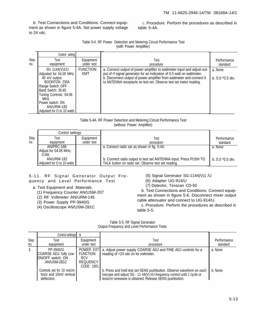
TM 11-6625-2946-14/TM 08168A-14/1
b. Test Connections and Conditions. Connect equip- C. Procedure. Perform the procedures as described inment as shown in figure 5-4A. Set power supply voltage table 5-4A.to 24 vdc.
Table 5-4. RF Power Detection and Metering Circuit Performance Test
Stepno.
Stepno.
Control settingTest
equipmentSG 1144(V)1/U
Adjusted for 54.05 MHz40 mV output.
BOONTON 230ARange Switch: OFFBand Switch: 35-65Tuning Controls: 54.06
MHzPower switch: ON
AN/URM-182Adjusted for O to 10 watts
Equipmentunder test
FUNCTION:XMT
(with Power Amplifier)
Testprocedure
a. Connect output of power amplifier to wattmeter input and adjust out-put of rf signal generator for an indication of 0.5 watt on wattmeter.b. Disconnect output of power amplifier from wattmeter and connect itto ANTENNA receptacle on test set. Observe test set meter reading.
Table 5-4A. RF Power Detection and Metering Circuit Performance Test
Control settingsTest
equipmentAN/PRC-168
Adjust for 54.05 MHz,0.5W.
AN/URM-182Adjusted for O to 10 watts
Equipmentunder test
(without Power Amplifier}
Testprocedure
a. Connect radio set as shown in fig. 5-4A.
b. Connect radio output to test set ANTENNA input. Press PUSH TOTALK button on radio set. Observe test set reading.
Performancestandard
a. None
b. 5.0 *0.5 div.
Performancestandard
a. None
b. 5.0 *0.5 div.
5 - 1 1 . R F S i g n a l G e n e r a t o r O u t p u t F r e - (5) Signal Generator SG-1144(V)1 /Uquency and Level Performance Test (6) Adapter UG-914/U
a. Test Equipment and Materials. (7) Detector, Texscan CD-50
(1) Frequency Counter AN/USM-207 b. Test Connections and Conditions. Connect equip-
(2) RF Voltmeter AN/URM-145 ment as shown in figure 5-6. Disconnect mixer output
(3) Power Supply PP-3940/G(4) Oscilloscope AN/USM-281C
cable attenuator and connect to UG-914/U.c. Procedure. Perform the procedures as described in
table 5-5.
Table S-5. RF Signal GeneratorOutput Frequency and Level Performance Tests
Controls set for 10 ms/cmhoriz and 10mV verticaldeflection.
sEquipment Testunder test procedure
POWER: EXTFUNCTION:
RCVREQUENCY
CODE: 1001
Control settingsStep Testno. equipment1 PP-3940/G
COARSE ADJ: fully ccwON/OFF switch: ON
AN/USM-281C
a. Adjust power supply COARSE ADJ and FINE ADJ controls for areading of +24 vdc on its voltmeter.
b. Press and hold test set SENS pushbutton. Observe waveform on oscil-loscope and adjust SG - 11 44(V) I/U frequency control until 1 cycle orless/cm sinewave is obtained. Release SENS pushbutton.
Performancestandard
a. None
b. None
5-13

TM 11-6625-2946-14/TM 08168A-14/1
Table S-S. RF Signal GeneratorOutput Frequency and Level Performance Tests -Continued
Stepno.
2
3
Control settingsTest
equipmentSG-l144(v)1/U
Preset for a 30.05 MHz40 mV output.
AN/USM-207Controls set to measure30.05 MHz.Same as step I
Same as step 1
Equipmentunder test
Same as step 1
Same as step 1.
Testprocedure
c. Disconnect test set from t-connector and using AN/USM-207, measurefrequency of rf signal at connector.
d. Press and hold test set SENS pushbutton. Using rf voltmeter, measurelevel of Test Set mixer output by disconnecting cable from W1P2J1 andmeasuring center lead.u. Set test set FREQUENCY CODE switches to 3001. ReadjustSG-1144(V)l/U for a 54.05-MHz, 40-mV output.b. Repeat steps I b, c, and d.
a. Set test set FREQUENCY CODE switches to 4793. ReadjustSG-1144(V)1/U for a 79.95 MHz 40 mv output.b. Press and hold test set SENS pushbutton. Observe waveform on oscil-loscope and adjust SG-1144(V)1 /U frequency control until a 1 cycle orless/cm sinewave is obtained. Release SENS pushbutton.c. Disconnect test set from t-connector and using AN/USM-207, measurefrequency of rf signal at connector.
d. Press and hold test set SENS pushbutton. Using rf voltmeter, measurelevel of test set mixer output by disconnecting cable from W1P2J1 andmeasuring center lead.
Performancestandard
c. 30.047 MHzmin30.052 MHz maxd. 20 mv min
a. None
b. 54.046 MHzmin54.054 MHz max20 mv mina. None
b. 79,95 MHz
c. 79.955 MHzmax79,945 MHz mind. 20.0 mv min
5-12. Receiver Sensi t iv i ty Measuring Cir- (3) Power Supply PP-3940/G
cu i t Per fo rmance Tes ts (4) Distortion Analyzer TS-723D/U.d. Test Connections and Conditions. Connect equip-
s. Test Equipment and Materials.(1) Audio Signal Generator AN/URM- 127
ment as shown in figure 5-7.
(2) Digital Voltmeter AN/USM+51c. Procedure. Perform the procedures as described in
table 5-6.
Table 5-6. Receiver Sensitivity Measuring Circuit Performance Test
Stepno.
Control settingsTest
equipmentPP-3940/P
COARSE ADJ: fully ccwON/OFF switch: ON
TS-723D/UPower switch: ONRange selectorswitch: 0 dB
AN/URM-127POWER switch: ONFREQ METER: ONFREQ RANGE MULTI-
PLIER: X10Vernier dial: 100OUTPUT CONTROL:
ccw
Equipmentunder test
POWER: EXTFUNCTION:
RCV
Testprocedure
a. Adjust power supply COARSE ADJ and FINE ADJ controls for areading of + 24 vdc on its voltmeter, Observe test set meter reading.b. Connect AN/URM-127 to test set AUDIO input and adjust AN/URM127 OUTPUT CONTROL for a reading of 5 units on test set meter.c. Using TS-723D/U, measure test set audio input signal in db. AdjustAN/URM-127 OUTPUT CONTROL to reduce its output 15 db on theanalyzer.d. Momentarily press test set SENS switch and observe reading on testset meter.
Performancestandard
a. IO div.
b. 5 *0.5 div.
c. None
d. 5 div. or more
5-13. Field Strength Measurement Circui t shielded wire with BNC connector on one end.Per fo rmance Tes t b. Test Connections and Conditions. As described in
the following procedure.a. Test Equipment and Materials.(1) RF Signal GeneratorSG-1144(V)1 /U c. Procedure. Perform the procedures as described in
(2) Cable, locally fabricated, 2 ft. insulated, un- table 5-7.
5-14

TM 11-6625-2946-14/TM 08168A-14/1
Figure 5-6. Rf Signal Generator Output Frequency and Level Test Setup
5 1 5

TM 11-6625-2946-14/TM 08168A-14/1
Figure 5-7. Receiver sensitivity measuring circuit test setup
5-16

TM 11-6625-2946-14/TM 08168A-14/1
Table 5-7. Field Strength Measurement Circuit Performance Test
Control settingsStep Testno. equipment
SG-1144(V)1/UAdjusted to measure0.5 vrms, 30.050 MHz
Equipmentunder test
POWER: EXTFUNCTION:
FSM
Testprocedure
a. Connect cable to output of the SG-1144(V)1/U and wrap five turns of#20 insulated wire around the test set antenna.b. Using a short (6” or less) clip lead, connect between ground on theSC-I 144(V) l/U and the test set.c. Adjust the output of the SG-1144(V)I /U for a level of 0.5 vrms andobserve reading on test set meter.—
Performancestandard
a. None
b. None
c. Approx-imately 5.0 div.
5-17


TM 11-6625-2946-14/TM 08168A-14/1
A P P E N D I X A
R E F E R E N C E S
DA Pam 310-4 Index of TechnicaI Manuals.,Technical Bulletins, SupplyManuals (Types 7, 8, and 9),Supply Bulletins, and Lubrica-tion Orders.
DA Pam 310-7 US Army Equipment Index ofModification Work Orders.
SC 5180-91-CL-R07 Tool Kit, Electronic Equipment,TK-105/G (NSN5180-00-610-8177)
SC 5180-91 -CL-R 13 Tool Kit, Electronic Equipment,TK-101/G(NSN 5180-00-064-5178)
SLI-2 (USMC) Index to Publications to Auth-orized Equipment.
TM 11-5820-882-10 Operator’s Manual: Radio SetAN/PRC-68.
TM 11-6130-247-14-1 Operator’s, Organizational, DS,and GS Maintenance Manual:Power Supply PP-3940A/G(NSN 6130-00-460-2148).
TM 11-6625-255-14 Operator’s, Organizational, DS,and GS Maintenance Manual:Spectrum Analyzer TS-723A/U, TS-723B/U, TS-723C/U and TS-723D/U(NSN 6625-00-668-7418).
TM 11-6625-524-14 Operator’s, Organizational, andField Maintenance Manual:Voltmeter, ElectronicAN/URM-145.
TM 11-6625-586-12 Operator’s and OrganizationalMaintenance Manual (In-cluding Repair Parts and
Special Tool Lists): GeneratorSignal AN/URM-103.
TM 1145625-683-15 Operator’s, Organizational, DS,GS, and Depot MaintenanceManual: Signal GeneratorAN/URM-127 (NSN6625-00-783-5%5).
TM 11-6625-7010 Operator’s Manual: DigitalReadout, Electronic CounterAN/USM-207 (NSN6625-00-91 1-6368).
TM 11-6625-2658-14 Operator’s, Organizational, DS,‘and GS Maintenance Manualfor OscilloscopeAn/USM-281C (NSN6625-00-106-%22)
1-6625-2718-14-1 Operator’s, Organizational, DS,and GS Maintenance Manual:Test Set, Radio Frequency,Power AN/URM-182A (NSN6625-00-148-9371).
TM 11-6625-2941-14 Operator’s, Organizational, DS,and GS Maintenance Manual:Counter, Electronic, DigitalReadout AN/USM-459 (to bepublished).
TM 38-750 The Army Maintenance Manage-ment System (TAMMS)
TM 750-244-2 Procedures for Destruction ofElectronics Materiel to Pre-vent Enemy Use (ElectronicsCommand).
TM 4700-15/1(USMC) Forms and Records Procedures.
A-1


TM 11-6625-2946-14/TM 08168A-14/1
A P P E N D I X B
M A I N T E N A N C E A L L O C A T I O N
Sect ion I . INTRODUCTION
B-1 . Genera l .
This appendix provides a summary of the maintenanceoperations for Test Set TS-3354/PRC-68. It authorizescategories of maintenance for specific maintenancefunctions on repairable items and components and thetools and equipment required to perform each function.This appendix may be used as an aid in planningmaintenance operations.
B-2 . Ma in tenance Func t ion .
Maintenance functions will be limited to and defined asfollows:
a. Inspect. To determine the serviceability of an itemby comparing its physical, mechanical, and/or electricalcharacteristics with established standards through ex-amination.
b. Test. To verify serviceability and to detect incipientfailure by measuring the mechanical or electricalcharacteristics of an item and comparing those charac-teristics with prescribed standards.
c. Service. Operations required periodically to keep anitem in proper operating condition, i.e., to clean (decon-taminate), to preserve, to drain, to paint, or to replenishfuel, lubricants, hydraulic fluids, or compressed air sup-plies.
d. Adjust. To maintain, within prescribed limits, bybringing into proper or exact position, or by setting theoperating characteristics to the specified parameters.
e. Align. To adjust specified variable elements of anitem to bring about optimum or desired performance.
f. Calibrate. To determine and cause corrections to bemade or to be adjusted on instruments or test measuringand diagnostic equipments used in precision measure-ment. Consists of comparisons of two instruments, oneof which is a certified standard of known accuracy, todetect and adjust any discrepancy in the accuracy of theinstrument being compared.
g. Install. The act of emplacing, seating, or fixing intoposition an item, part, module (component or assembly)in a manner to allow the proper functioning of the equip-ment or system.
h. Replace. The act of substituting a serviceable liketype part, subassembly, or module (component orassembly) for an unserviceable counterpart.
i. Repair. The application of maintenance services (in-spect, test, service, adjust, align, calibrate, replace) orother maintenance actions (welding, grinding, riveting,
straightening, facing, remachining, or resurfacing) torestore serviceability to an item by correcting specificdamage, fault, malfunction, or failure in a part,subassembly, module (component or assembly), enditem, or system.
j. Overhaul. That maintenance effort (service/action)necessary to restore an item to a completely ser-viceable/operational condition as prescribed bymaintenance standards (i.e., DMWR) in appropriatetechnical publications. Overhaul is nromally the highestdegree of maintenance performed by the Army.Overhaul does not normally return an item to like newcondition.
k. Rebuild. Consists of those services/actionsnecessary for the restoration of unserviceable equipmentto a like new condition in accordance with originalmanufacturing standards. Rebuild is the highest degreeof materiel maintenance applied to Army equipment.The rebuild operation includes the act of returning tozero those age measurements (hours, miles, etc. ) con-sidered in classifying Army equipments/components.
B-3 . Co lumn Ent r ies .
a. Column 1, Group Number. Column 1 lists groupnumbers, the purpose of which is to identify com-ponents, assemblies, subassemblies, and modules withthe next higher assembly.
b. Column 2, Component/Assembly. Column 2 con-tains the noun names of components, assemblies,subassemblies, and modules for which maintenance isauthorized.
c. Column 3, Maintenance Functions. Column 3 liststhe functions to be performed on the item listed in col-umn 2. When items are listed without maintenance func-tions, it is solely for purpose of having the groupnumbers in the MAC and RPSTL coincide.
d. Column 4, Maintenance Category. Column 4specifies, by the listing of a “work time” figure in theappropriate subcolumn(s), the lowest level of main-tenance authorized to perform the function listed incolumn 3. This figure represents the active time requiredto perform that maintenance function at the indicatedcategory of maintenance. If the number or complexity ofthe tasks within the listed maintenance function vary atdifferent maintenance categories, appropriate “work-time” figures will be shown for each category. Thenumber of task-hours specified by the “work time”
B-1

TM 11-6625-2946-14/TM 08168A-14/1
figure represents the average time required to restore anitem (assembly, subassembly, component, module, enditem or system) to a serviceable condition under typicalfield operating conditions. This time includes prepara-tion time, troubleshooting time, and quality assurance/quality control time in addition to the time required toperform the specific tasks identified for the maintenancefunctions authorized in the maintenance allocationchart. Subcolumns of column 4 are as follows:
C—Operator/CrewO—OrganizationalF—Direct SupportH—General SupportD—Depot
e. Column 5, Tools and Equipment. Column 5specifies by code those common tool sets (not individualtools) and special tools, test, and support equipment re-quired to perform the designated function.
f. Column 6, Remarks. Column 6 contains analphabetic code which leads to the remark in section IV,Remarks, which is pertinent to the item opposite the par-ticular code.
B - 4 . T o o l a n d T e s t E q u i p m e n t R e -quirements (See II I)
a. Tool or Test Equipment Reference Code. Thenumbers in this column coincide with the numbers usedin the tools and equipment column of the MAC. Thenumbers indicate the applicable tool or test equipmentfor the maintenance functions.
b. Maintenance Category. The codes in this columnindicate the maintenance category allocated the tool ortest equipment.
c. Nomenclature. This column lists the noun nameand nomenclature of the tools and test equipment re-quired to perform the maintenance functions.
d. National/NATO Stock Number. This column liststhe National/NATO stock number of the specific tool ortest equipment.
e. Tool Number. This column lists the manufacturer’spart number of the tool followed b; the Federal SupplyCode for manufacturers (5-digit) in parentheses.
B-5. Remarks (Sec IV)
a. Reference Code. This code refers to the appropriateitem in section II, column 6.
b. Remarks. This column provides the required ex-planatory information necessary to clarify items appear-ing in section 11.
(Next printed page is B-3)
B-2

TM 11-6625-2946-14TM 08168A-14/1
(1)GROUP
NUMBER
00
01
0101
0102
0103
0104
0105
0106
02
0304
SECTION II MAINTENANcE ALLOCATION CHARTFOR
TEST SET TS-3354/PRC-68
(2)COMPONENT/ASSEMBLY
TEST SET TS-3354/PRC-68 705559-801
ELECTRONIC COMPONENT ASSEMBLY 917837-8o1
RF GENERATOR ASSEMBLY 914451-801
METER FUNCTION ASSEMBLY 914272-801
ATTENUATOR/POWER MONITOR 914267-801
SYNTHESIZER ASSEMBLY 914265-801
VCO ASSEMBLY 917833-803
FRONT PANEL ASSEMBLY 159564-801
AUDIO CABLE ASSEMBLYAND
RF CABLE ASSEMBLYCASE ASSEMBLY 914271-801
(3)MAINTENANCE
FUNCTlON
InspectServiceRepaircalibrateInspectTest
Adjust
RepairInspectReplaceTestRepair
InspectReplaceTestRepair
InspectReplaceTestRepair
InspectRep LaceInspectReplaceInspectTestRepairInspectReplaceTestRepsairInspectRepair
—c
—
.
MAINTENANCE—o
—.20.10.10
.10
.20
—F
—
—
CATEGORY
H
.40
.05
.30
.10
.40
.05
.20
.10
.30
.10
.50
.10
.20
.05
.10
.05
.10.20
.10
.20
.05
.40
D
.20
.50
.20
.50
.20,50
(5)TOOLS
ANDEQPT.
112 thru
2,3,4,8,912 thru152,3,4,8,9 11 thru152 thru
112 thru15,162 thru11,15,16
2,3,4,8,10,172,3,4,8,11,17
2,4,9,1215,18,2,4, 9,1112,15,18
2,11
2,11
11
(6)REMARKS
A
B
c
c
c
E
F
D
c
B-3
11

TM 11-6625-2946-14TM 08168A-14/l
SECTION III TOOL AND TEST EQUIPMENT REQUIREMENTSFOR
TEST SET TS-3354/PRC-68
TOOL OR TESTEQUIPMENTREF CODE
12
34
56
789
101112131415
161718
MAINTENANCECATEGORY
oH,D
H,DH,D
H,DH,D
H,DH,DH,DH,DH,DH,DHHH,D
DDD
NOMENCLATURE NATIONAL/NATOSTOCK NUMBER
TOOL KIT, ELECTRONICS EQUIPMENT TK-101/G 5180-00-064-5178
MULTIMETER DIGITAL AN/USM-451 6625-01-060-6804
VOLTMETER DIGITAL AN/GSM-64B 6625-00-022-7894
POWER SUPPLY, PP-3940/G (QTY TWO) 6130-00-404-1727
RF SIGNAL GENERATOR AN/URM-103 6625-00-868-8352
RF SIGNAL GENERATOR SG-1144/URF VOLTMETER AN/URM-145 6625-00-973-3986
FREQUENCY COUNTER AN/USM-459 6625-00-061-8929
FREQUENCY COUNTER AN/USM-207 6625-00-817-8909
OSCILLOSCOPE AN/USM-281C 6625-00-053-3112
AUDIO SIGNAL GENERATOR AN/URM-127 662 S-00-783-5965
WATTMETER AN/URM-182 6625-00-148-9271
DISTORTION ANALYZER TS-723/U 6625-00-668-9418TOOL KIT, ELECTRONIC EQUIPMENT TK-105/G 5180-00-610-8177
AN/PRC-68 RADIO SET 5820-01-079-9260
DETECTOR UC-274A/U 5935-00-201-2411
ADAPTER UG-914/UINTRF. MEASURING DEVICE AN/URM-85 6625-00-776-0595
INTRF. MEASURING DEVICE AN/URM-200or
INTRF. MEASURING DEVICE N.F. 105 WITH T1/NF-105 5985-00-769-4227
TEST FIXTURE, RF GENERATOR AsSEMBLYTEST FIXTURE, METER FuNCTION BOARDTEST FIXTURE ATTENUATOR/POWER METER AS ASSEMBLY
TOOL NUMBER
B-4

TM 11-6625-2946-14TM 08168A-14/l
REFERENCECODE
A
B
c
D
E
F
G
SECTION IV. REMARKS
REMARKS
REPAIR OF THE TEST SET AT THE
FRONT PANEL KNOBS.
REPAIR OF THE TEST SET AT THE
CONTROLS, SWITCHES, THE METER
BOTH CABLES.
ORGANIZATIONAL LEVEL OF MAINTENANCE CONSISTS OF TIGHTENING/REPLACING
GENERAL SUPPORT LEVEL OF MAINTENANCE CONSISTS OF REPLACING FRONT PANEL
ATTENUATOR/POWER METER ASSEMBLY, THE SYNTHESIZER, THE VCO MODULE AND
REPAIR CONSISTS OF FAULT ISOLATION AND REPAIR BY REPLACEMENT OF PIECE PARTS.
REPAIR WITH STOCKED CONNECTORS AND CABLES
SEND TO DEPOT FOR EVALUATION
THE VCO MODULE IS THROWAWAY
REPAIR OF CASE ASSEMBLY CONSISTS OF REPLACEMENT OF HINGES, LATCHES, AND THE HANDLE.
B-5/(B-6 blank)


TM 11-6625-2946-14/TM08168A-14/1
A P P E N D I X C
C O M P O N E N T S O F E N D I T E M A N D B A S I C I S S U E I T E M S L I S T S
Sec t ion L INTRODUCTION
C-1 . Scope
This appendix lists components of end item and basicissue items for the Test Set TS-3354/PRC-68 to helpyou inventory items required for safe and efficientoperation. Marine Corps Units should refer to SL3-06827A.
C-2 . Genera l
The Components of End Item and Basic Issue ItemsLists are divided into the following sections:
a. Section II—Components of End Item. This listingis for informational purposes only, and is not authorityto requisition replacements. These items are part of theend item, but are removed and separately packaged fortransportation or shipment. As part of the end item,these items must be with the end item whenever it isissued or transferred between property accounts. Il-lustrations are furnished to assist you in identifying theitems.
b. Section HI-Basic Issue Items. These are theminimum essential items required to place the Test Set inoperation, to operate it, and to perform emergencyrepairs. Although shipped separately packaged, BIImust be with the Test set during operation and wheneverit is transferred between properly accounts. The illustra-tions will assist you with hard-to-identify items. Thismanual is your authority to request/requisition replace-ment BII, based on TOE/MTOE authorization of theend item.
C-3 . Exp lana t ion o f Co lumns
The following provides an explanation of columnsfound in the tabular listings:
a. Column (1)—Illustration Number (Illus Number).This column indicates the number of the illustration inwhich the item is shown.
b. Column (2)—National Stock Number. Indicatesthe National stock number assigned to the item. The Na-tional stock numbers in section 111 will be used for re-quisitioning basic issue items.
c. Column (3)—Description. Indicates the Nationalitem name and, if required, a minimum description toidentify and locate the item. The last line for each itemindicates the FSCM (in parentheses) followed by the partnumber.
d. Column (4)—Unit of Measure (U/M). Indicates themeasure used in performing the actual operational/-maintenance function. This measure is expressed by atwo-character alphabetical abbreviation (e.g., ea, in,pr).
e. Column (5)—Quantity required (Qty Rqd). In-dicates the quantity of the item authorized to be usedwith/on the equipment,
(Next printed page is C-3)
C-1

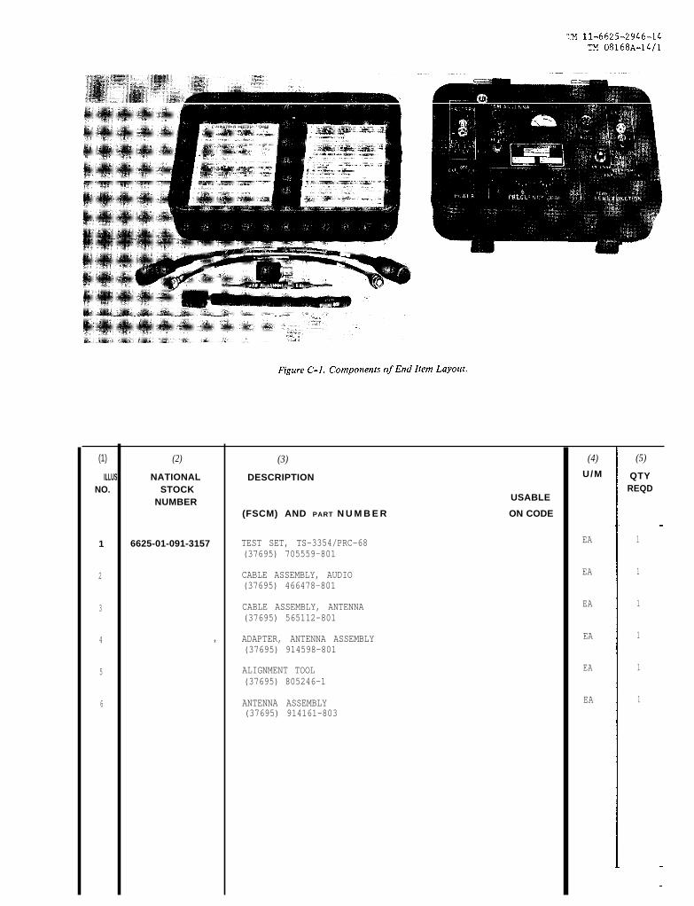
Figure C-1.
TM 11-6625-2946-14 TM 08168A-14/1
(1) (2) (3) (4) (5)
ILLUS NATIONAL DESCRIPTION U/M QTYNO. STOCK REQD
NUMBER USABLE
(FSCM) AND PART N U M B E R ON CODE
1 6625-01-091-3157 TEST SET, TS-3354/PRC-68 EA 1
(37695) 705559-801
2 CABLE ASSEMBLY, AUDIO EA 1
(37695) 466478-801
3 CABLE ASSEMBLY, ANTENNA EA 1
(37695) 565112-801
4 ADAPTER, ANTENNA ASSEMBLY EA 1*
(37695) 914598-801
5 ALIGNMENT TOOL EA 1
(37695) 805246-1
6 ANTENNA ASSEMBLY EA 1
(37695) 914161-803


TM 11-6625-2946-14/TM 08168A-14/1
A P P E N D I X E
E X P E N D A B L E S U P P L I E S A N D M A T E R I A L S L I S T
Sect ion 1. INTRODUCTION
E-1 . Scope
This appendix lists expendable supplies and materialsyou will need to operate and maintain the Test Set TS-3354/PRC-68. These items are authorized to you byCTA 50-970, Expendable Items (Except Medical, ClassV, Repair Parts, and Heraldic Items).
E-2 . Exp lana t ion o f Co lumns
a. Column l—Item number. This number is assignedto the entry in the listing and is referenced in the nar-rative instructions to identify the material (e.g., “Usecleaning compound, item 5, App. D’').
b. Column 2—Level. This column identifies the lowestlevel of maintenance that requires the listed item.
C—Operator/CrewO—Organizational Maintenance/Aviation Unit
Maintenance
F—Direct Support Maintenance Aviation inter-mediate Maintenance
H—General Support Maintenancec. Column 3—National Stock Number. This is the Na-
tional stock number assigned to the item; use it to re-quest or requisition the item.
d. Column 4—Description. Indicates the Federal itemname and, if required, a description to identify the item.The last line for each item indicates the Federal Supplycode for Manufacturer (FSCM) in parentheses followedby a part number.
e. Column 5—Unit of Measure (U/M). indicates themeasure used in performing the actual maintenancefunction. This measure is expressed by a two-characteralphabetical abbreviation (e. g., ea, in, pr). If the unit ofmeasure differs from the unit of issue, requisition thelowest unit of issue that will satisfy your requirements.
(Next printed page is E-3)
E-1


TM 11-6625-2946-14TM 08168A-14/l
(1)ITEM
NO.
1234567
(2)LEVEL
o000000
(3)NATIONAL
STOCKNUMBER
020-00-721-9657305-00-222-2423
850-00-177-5094850-00-984-5853
SECTION II EXPENDABLE SUPPLIES AND MATERIALS LIST
(4)DESCRIPTION
PART NO. AND FSCM
BRUSH, PAINTCLOTH, LINT-FREEPAINTSANDPAPERSILICONE GREASE
SOLVENT (TRICHLOROTRIFLUOROETHANE)THINNER
(5)
U/M
EAYDOZSHOZCALGAL
E-3/(E-4 blank)


TM 11-6625-2948-14/TM 08168-14/1
Figure FO-1. Test Set TS-3354/PRC-68, Schematic Diagram(Sheet 1 of 6)

TM 11-6625-2946-14/TM 08168A-14/1
Figure FO-1. Test Set TS-3354/PRC-68, Schematic Diagram(Sheet 2 of 6)

TM 11-6625-2946-14/TM 08168A-14/1
Figure FO-1. Test Set TS-3354/PRC-68, Schematic Diagram(Sheet 3 of 6).

TM 11-6625-2946-14/TM 08168A-14/1
Figure FO-1. Test Set TS-3354/PRC-68. Schematic Diagram(Sheet 4 of 6).

TM 11-6625-2946-14/TM 08168A-14/1
Figure FO-1. Test Set TS-33254/PRC-68, Schematic Diagram(Sheet 5 of 6).

TM 11-6625-2946-14/TM 08168A-14/1
Figure FO-1. Test Set TS-3354/PRC-68, Schematic Diagram(Sheet 6 of 6).

By Order of the Secretary of the Army:
Official:
J. C. PENNINGTONMajor General, United States Army.
The Adjutant General
Distribution:Active Army:
HISA (Ft Monmouth) (21)USAINSCOM (2)COE (1)TSG (1)USAARENBD (1)DARCOM (1)TRADOC (2)OS Maj Cmd (4)TECOM (2)USACC (4)MDW (1)Armies (2)Corps (2)Svc Colleges (1)USASIGS (5)USAADS (2)USAFAS (2)USAARMS (2)USAIS (2)USAES (2)USAICS (3)MAAG (1)USARMIS (1)USAERDAA (1)USAERDAW (1)Ft Gordon (10)Ft Carson (5)Army Dep (I) except
SAAD (30)TOAD (14)SHAD (2)
Ft Gillem (10)USA Dep (1)Sig Sec USA Dep(1)Ft Richardson (CERCOM Ofc) (2)Units org under fol TOE:
29-207 (2)29-610 (2)
NC: NoneUSAR: None
For explanation of abbreviations used, sec AR 3 IO-SO.
E. C. MEYERGeneral, United States Army
Chief of Staff

DEPARTMENT OF THE ARMYUS ARMY AG PUBLICATIONS CENTER
1655 WOOD SON ROADST. LOUIS, MISSOURI 63114
OFFICIAL BUSINESSPENALTY FOR PRIVATE US E. S300
POSTAGE AND FEES PAIDDEPARTMENT OF THE ARMY
DOD 314FOURTH CLASS

This fine document...
Was brought to you by me:
Liberated Manuals -- free army and government manuals
Why do I do it? I am tired of sleazy CD-ROM sellers, who take publicly available information, slap “watermarks” and other junk on it, and sell it. Those masters of search engine manipulation make sure that their sites that sell free information, come up first in search engines. They did not create it... They did not even scan it... Why should they get your money? Why are not letting you give those free manuals to your friends?
I am setting this document FREE. This document was made by the US Government and is NOT protected by Copyright. Feel free to share, republish, sell and so on.
I am not asking you for donations, fees or handouts. If you can, please provide a link to liberatedmanuals.com, so that free manuals come up first in search engines:
<A HREF=http://www.liberatedmanuals.com/>Free Military and Government Manuals</A>
– SincerelyIgor Chudovhttp://igor.chudov.com/
– Chicago Machinery Movers