armstrong pump trap
DESCRIPTION
Pump TrapTRANSCRIPT
7/21/2019 Armstrong Pump Trap
http://slidepdf.com/reader/full/armstrong-pump-trap 1/12
This bulletin should be used by experienced personnel as a guide to the installation and maintenance of the
Pumping Trap or Pumping Trap Package. Selection or installation of equipment should always be accompanied
by competent technical assistance. We encourage you to contact Armstrong or your local Representative if
further information is required.
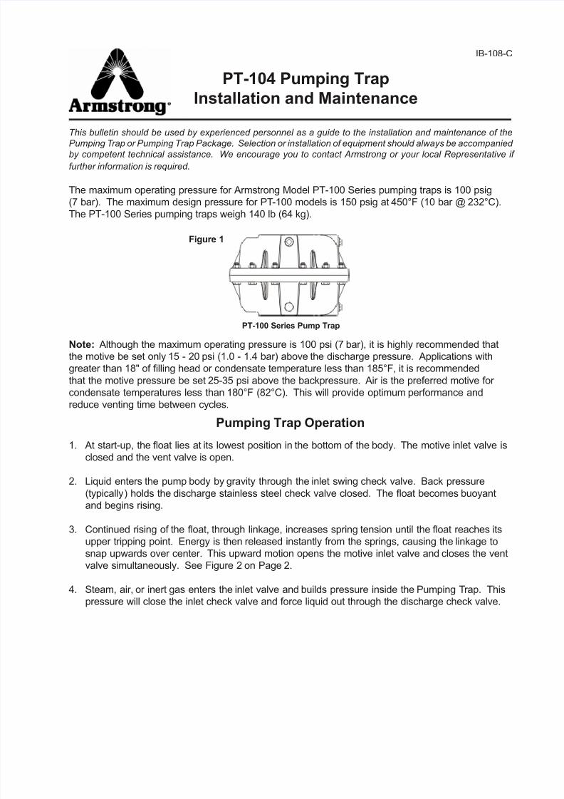
The maximum operating pressure for Armstrong Model PT-100 Series pumping traps is 100 psig
(7 bar). The maximum design pressure for PT-100 models is 150 psig at 450°F (10 bar @ 232°C).
The PT-100 Series pumping traps weigh 140 lb (64 kg).
Note: Although the maximum operating pressure is 100 psi (7 bar), it is highly recommended that
the motive be set only 15 - 20 psi (1.0 - 1.4 bar) above the discharge pressure. Applications with
greater than 18" of lling head or condensate temperature less than 185°F, it is recommended
that the motive pressure be set 25-35 psi above the backpressure. Air is the preferred motive for
condensate temperatures less than 180°F (82°C). This will provide optimum performance and
reduce venting time between cycles.
Pumping Trap Operation
1. At start-up, the oat lies at its lowest position in the bottom of the body. The motive inlet valve is
closed and the vent valve is open.
2. Liquid enters the pump body by gravity through the inlet swing check valve. Back pressure
(typically) holds the discharge stainless steel check valve closed. The oat becomes buoyant
and begins rising.
3. Continued rising of the oat, through linkage, increases spring tension until the oat reaches its
upper tripping point. Energy is then released instantly from the springs, causing the linkage to
snap upwards over center. This upward motion opens the motive inlet valve and closes the ventvalve simultaneously. See Figure 2 on Page 2.
4. Steam, air, or inert gas enters the inlet valve and builds pressure inside the Pumping Trap. This
pressure will close the inlet check valve and force liquid out through the discharge check valve.
PT-104 Pumping Trap
Installation and Maintenance
IB-108-C
PT-100 Series Pump Trap
Figure 1
7/21/2019 Armstrong Pump Trap
http://slidepdf.com/reader/full/armstrong-pump-trap 2/12
2
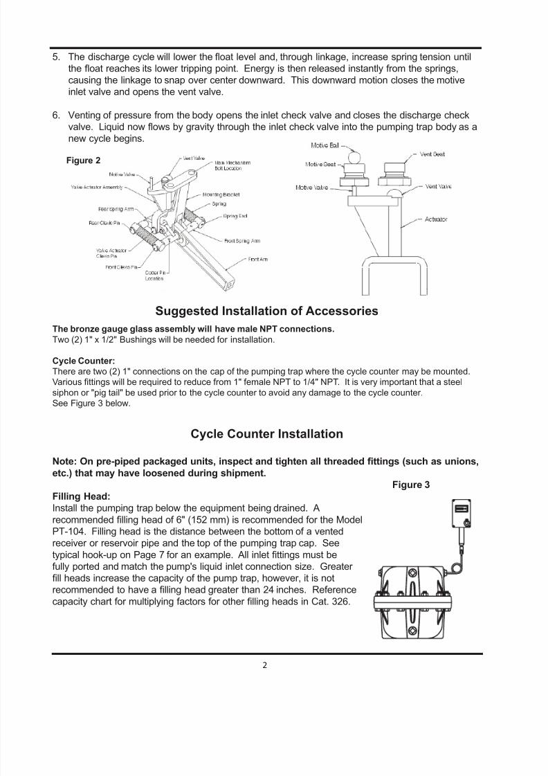
5. The discharge cycle will lower the oat level and, through linkage, increase spring tension until
the oat reaches its lower tripping point. Energy is then released instantly from the springs,
causing the linkage to snap over center downward. This downward motion closes the motive
inlet valve and opens the vent valve.
6. Venting of pressure from the body opens the inlet check valve and closes the discharge check
valve. Liquid now ows by gravity through the inlet check valve into the pumping trap body as a
new cycle begins.
Suggested Installation of Accessories
The bronze gauge glass assembly will have male NPT connections.
Two (2) 1" x 1/2" Bushings will be needed for installation.
Cycle Counter:
There are two (2) 1" connections on the cap of the pumping trap where the cycle counter may be mounted.
Various ttings will be required to reduce from 1" female NPT to 1/4" NPT. It is very important that a steel
siphon or "pig tail" be used prior to the cycle counter to avoid any damage to the cycle counter.
See Figure 3 below.
Cycle Counter Installation
Note: On pre-piped packaged units, inspect and tighten all threaded ttings (such as unions,
etc.) that may have loosened during shipment.
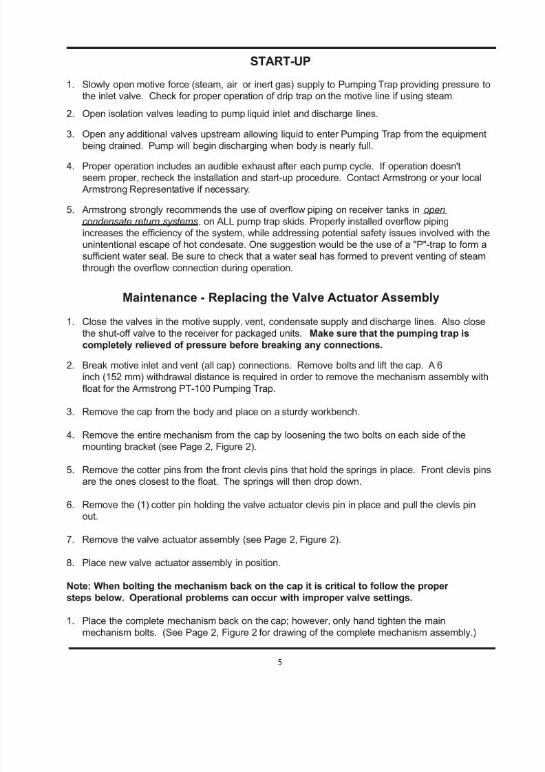
Figure 3
Filling Head:
Install the pumping trap below the equipment being drained. A
recommended lling head of 6" (152 mm) is recommended for the Model
PT-104. Filling head is the distance between the bottom of a vented
receiver or reservoir pipe and the top of the pumping trap cap. Seetypical hook-up on Page 7 for an example. All inlet ttings must be
fully ported and match the pump's liquid inlet connection size. Greater
ll heads increase the capacity of the pump trap, however, it is not
recommended to have a lling head greater than 24 inches. Reference
capacity chart for multiplying factors for other lling heads in Cat. 326.
Figure 2

7/21/2019 Armstrong Pump Trap
http://slidepdf.com/reader/full/armstrong-pump-trap 3/12
3
Liquid Reservoir:
Liquid owing from the equipment being drained must be stored during the pump’s discharge cycle.
A liquid reservoir (pipe reservoir) or vented receiver should be installed in a horizontal plane to
prevent ooding of equipment. Please contact your local Armstrong representative for questions
regarding reservoir pipe sizing or reference reservoir sizing data in catalog 326. Also see typical
hook-ups on Page 7.
Check Valves:NOTE: The pumping trap will not function without inlet and discharge check valves.
Connect the Armstrong supplied check valves to the pump. The swing check is the inlet check
valve and the spring assisted valve is used at the pump discharge. The use of Armstrong
supplied check valves is necessary to ensure the pump will attain published capacities.
Stainless steel in-line spring type check valves are recommended for applications where the
differential pressure between the motive pressure and back pressure is greater than 25 psi. For air
or 40 psi steam, stainless steel check valves are also a good choice for critical applications where
the extended life of the stainless steel check valve would be of great value.
The following guidelines apply if the Pumping Trap is installed without Armstrong supplied check
valves.
-- Inlet check valves should be bronze swing type with teon disc, Class 150 (minimum). Pipe sizeof the check valve must match the size of the pump's liquid inlet connection.
-- Discharge check valve should be in-line spring assist type, Class 150 (minimum) and match the
size of the pump's liquid discharge connection.
Motive Inlet Piping:
Connect the motive force piping (steam, air or inert gas) to the inlet connection on the pump cap.
Proper piping and trapping of the motive supply line must include a strainer, check valve, properly
sized drip leg with mud pocket, and drip trap (for steam motive). The drip trap discharge line should
be connected to the reservoir piping or vented receiver when practical. See Figure 5 and 6 on Page
7. It is recommended to install a union near the motive inlet.
Note: To visually determine the location of the motive connection for Series PT-104, see Figure 4
below.
18.5
1/2” - 13 LiftingLug Connection2 Places
.36
1.25
5.5
1/2” NPT MotiveConnection
13.5 12.50
12.03
1.30
10.07
Outlet OptionalOutlet
Optional Inlet/OutletConnection
1” NPT 6 Places
6” WithdrawlHeight
10.73
Optional Inlet1/2” NPT VentConnection
CycleCounter
Connection
Figure 4

7/21/2019 Armstrong Pump Trap
http://slidepdf.com/reader/full/armstrong-pump-trap 4/12
4
Maximum operating pressures for the pump trap 100 psi (7 bar). A pressure reducing valve
must be used when the motive pressure exceeds 100 psi (7 bar). It is also recommended that
motive pressure be set between 15-20 psi (1.0 - 1.4 bar) above the total discharge pressure (total
discharge pressure = vertical lift in psi plus return line pressure). This pressure setting keeps
venting time to a minimum and, when using steam, reduces the temperature differential. The PRV
should be installed as far from the pump trap as possible. A good rule is to use a minimum of 10' of
1" pipe between PRV and pump inlet.
Installation of a safety relief valve and pressure gauge is recommended in the motive force supply
line. The relief valve should be set for 125 psig (9 bar).
Vent Connection ("Open System" - vented to atmosphere):
Piping from the pump's cap connection labeled "Vent" should be installed vertically upward when
possible and unrestricted. If piping travels greater than three feet, the piping should be expanded to
one inch or greater. If a horizontal run is required, this line should be pitched toward the pump trap
in order to be self draining. It is recommended to install a union near the vent connection.
Note: To visually determine the location of the vent connection for Series PT-104, see Figure 4
on page 3.
Vent Connection (Closed loop system):
From the pump cap connection labeled "Vent", the equalizing line should be routed to the top of the
reservoir piping or the outlet piping immediately after the heat exchange equipment. An Armstrong
thermostatic air vent is recommended (for steam) at the high point of the exhaust line.
(See Figure 8 on Page 7.) Piping of the equalizing line should be a minimum 3/4" (20 mm) diameter
and must be pitched in order to be self draining.
If pressure from the equipment being drained could ever exceed back pressure, a properly sized
inverted bucket steam trap with a large vent or a oat and thermostatic trap must be installed
between the pump and discharge check valve. See Figure 8 on Page 7.
Packaged Receiver Vent Connections: The receiver vent must be unrestricted andatmospherically vented unless an ASME coded tank in a closed loop arrangement is specied.
Packaged Pump Trap Vent Connections: Piping from the pump's cap connection labeled "vent"
should be installed upward to connect with the receiver vent line, and be a minimum of one
3/4" (20 mm) diameter.
NOTE: Replace any temporary plastic plugs in these connections with permanent steel plugs
or appropriate ttings before start-up.
7/21/2019 Armstrong Pump Trap
http://slidepdf.com/reader/full/armstrong-pump-trap 5/12
5
START-UP
1. Slowly open motive force (steam, air or inert gas) supply to Pumping Trap providing pressure to
the inlet valve. Check for proper operation of drip trap on the motive line if using steam.
2. Open isolation valves leading to pump liquid inlet and discharge lines.
3. Open any additional valves upstream allowing liquid to enter Pumping Trap from the equipmentbeing drained. Pump will begin discharging when body is nearly full.
4. Proper operation includes an audible exhaust after each pump cycle. If operation doesn't
seem proper, recheck the installation and start-up procedure. Contact Armstrong or your local
Armstrong Representative if necessary.
5. Armstrong strongly recommends the use of overow piping on receiver tanks in open
condensate return systems, on ALL pump trap skids. Properly installed overow piping
increases the efciency of the system, while addressing potential safety issues involved with the
unintentional escape of hot condesate. One suggestion would be the use of a "P"-trap to form a
sufcient water seal. Be sure to check that a water seal has formed to prevent venting of steam
through the overow connection during operation.
Maintenance - Replacing the Valve Actuator Assembly
1. Close the valves in the motive supply, vent, condensate supply and discharge lines. Also close
the shut-off valve to the receiver for packaged units. Make sure that the pumping trap is
completely relieved of pressure before breaking any connections.
2. Break motive inlet and vent (all cap) connections. Remove bolts and lift the cap. A 6
inch (152 mm) withdrawal distance is required in order to remove the mechanism assembly with
oat for the Armstrong PT-100 Pumping Trap.
3. Remove the cap from the body and place on a sturdy workbench.
4. Remove the entire mechanism from the cap by loosening the two bolts on each side of the
mounting bracket (see Page 2, Figure 2).
5. Remove the cotter pins from the front clevis pins that hold the springs in place. Front clevis pins
are the ones closest to the oat. The springs will then drop down.
6. Remove the (1) cotter pin holding the valve actuator clevis pin in place and pull the clevis pin
out.
7. Remove the valve actuator assembly (see Page 2, Figure 2).
8. Place new valve actuator assembly in position.
Note: When bolting the mechanism back on the cap it is critical to follow the proper
steps below. Operational problems can occur with improper valve settings.
1. Place the complete mechanism back on the cap; however, only hand tighten the main
mechanism bolts. (See Page 2, Figure 2 for drawing of the complete mechanism assembly.)
7/21/2019 Armstrong Pump Trap
http://slidepdf.com/reader/full/armstrong-pump-trap 6/12
6
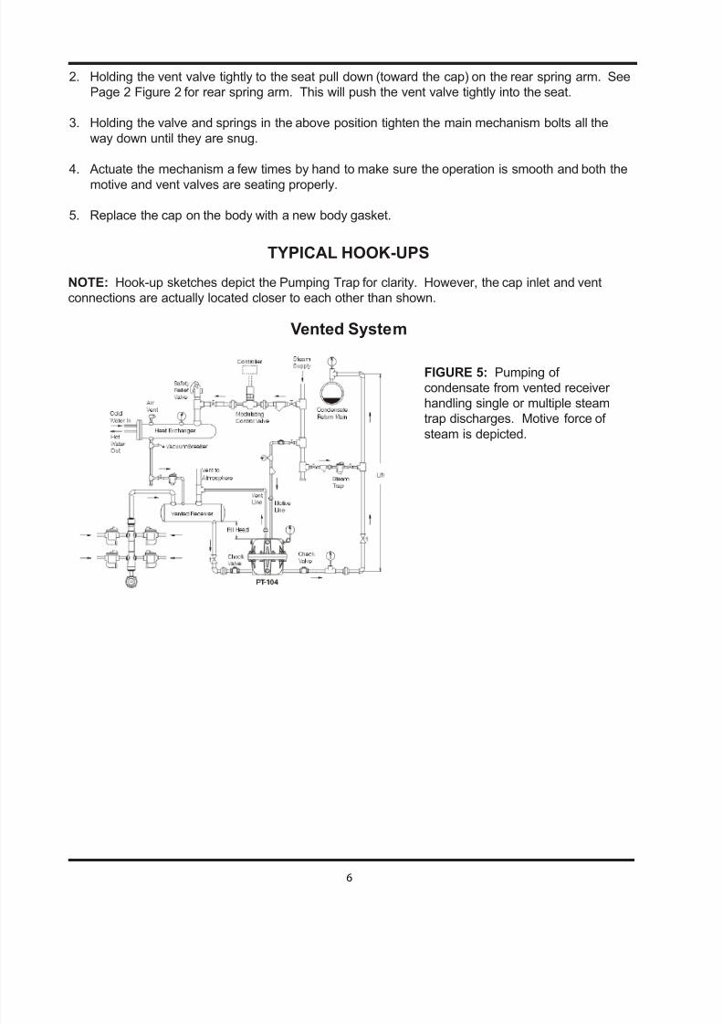
FIGURE 5: Pumping of
condensate from vented receiver
handling single or multiple steam
trap discharges. Motive force of
steam is depicted.
TYPICAL HOOK-UPS
NOTE: Hook-up sketches depict the Pumping Trap for clarity. However, the cap inlet and vent
connections are actually located closer to each other than shown.
Vented System
2. Holding the vent valve tightly to the seat pull down (toward the cap) on the rear spring arm. See
Page 2 Figure 2 for rear spring arm. This will push the vent valve tightly into the seat.
3. Holding the valve and springs in the above position tighten the main mechanism bolts all the
way down until they are snug.
4. Actuate the mechanism a few times by hand to make sure the operation is smooth and both the
motive and vent valves are seating properly.
5. Replace the cap on the body with a new body gasket.
7/21/2019 Armstrong Pump Trap
http://slidepdf.com/reader/full/armstrong-pump-trap 7/12
7
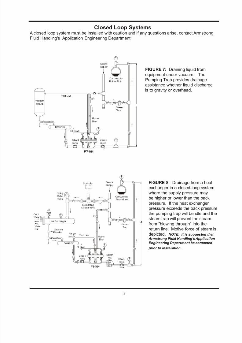
FIGURE 7: Draining liquid from
equipment under vacuum. The
Pumping Trap provides drainage
assistance whether liquid discharge
is to gravity or overhead.
FIGURE 8: Drainage from a heat
exchanger in a closed-loop system
where the supply pressure may
be higher or lower than the back
pressure. If the heat exchanger
pressure exceeds the back pressure
the pumping trap will be idle and the
steam trap will prevent the steam
from "blowing through" into the
return line. Motive force of steam is
depicted. NOTE: It is suggested that
Armstrong Fluid Handling's ApplicationEngineering Department be contacted
prior to installation.
Closed Loop Systems A closed loop system must be installed with caution and if any questions arise, contact Armstrong
Fluid Handling's Application Engineering Department.
7/21/2019 Armstrong Pump Trap
http://slidepdf.com/reader/full/armstrong-pump-trap 8/12
8
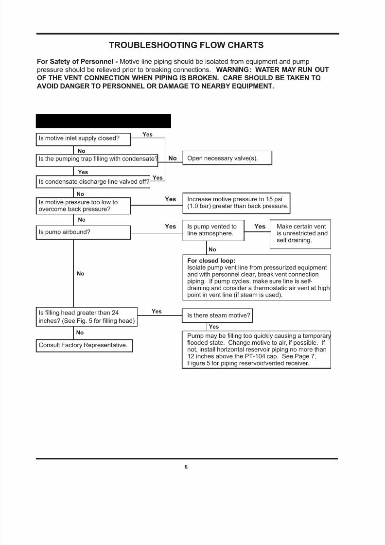
Is motive inlet supply closed?
Is the pumping trap lling with condensate?
Is condensate discharge line valved off?
Is motive pressure too low toovercome back pressure?
Is pump airbound?
Is lling head greater than 24
inches? (See Fig. 5 for lling head)
Consult Factory Representative.
No Open necessary valve(s).
Yes Increase motive pressure to 15 psi(1.0 bar) greater than back pressure.
Yes Is pump vented to Yes Make certain ventline atmosphere. is unrestricted and
self draining.
For closed loop: Isolate pump vent line from pressurized equipment
and with personnel clear, break vent connectionpiping. If pump cycles, make sure line is self-draining and consider a thermostatic air vent at highpoint in vent line (if steam is used).
Is there steam motive?
Pump may be lling too quickly causing a temporary ooded state. Change motive to air, if possible. If not, install horizontal reservoir piping no more than 12 inches above the PT-104 cap. See Page 7,
Figure 5 for piping reservoir/vented receiver.
No
No
Yes
No
No
TROUBLESHOOTING FLOW CHARTS
For Safety of Personnel - Motive line piping should be isolated from equipment and pump
pressure should be relieved prior to breaking connections. WARNING: WATER MAY RUN OUT
OF THE VENT CONNECTION WHEN PIPING IS BROKEN. CARE SHOULD BE TAKEN TO
AVOID DANGER TO PERSONNEL OR DAMAGE TO NEARBY EQUIPMENT.
1. Pump Does Not Cycle During Start-Up
Yes
Yes
No
YesNo
Yes
7/21/2019 Armstrong Pump Trap
http://slidepdf.com/reader/full/armstrong-pump-trap 9/12
9
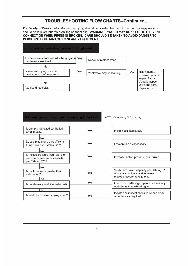
Are defective steam traps discharging into
condensate inlet line?
Is reservoir piping or vented
receiver used before pump?
Add liquid reservior.
2. Excessive ash steam passed through vent
Isolate pump,
remove cap, and
inspect for dirt.
Visually inspect
valve and seat.
Replace if worn.
Yes
Yes
Yes
Yes
Yes
Yes
3. Pump cycles but equipment or piping is ooded NOTE: See catalog 326 for sizing.
TROUBLESHOOTING FLOW CHARTS--Continued...
For Safety of Personnel - Motive line piping should be isolated from equipment and pump pressure
should be relieved prior to breaking connections. WARNING: WATER MAY RUN OUT OF THE VENT
CONNECTION WHEN PIPING IS BROKEN. CARE SHOULD BE TAKEN TO AVOID DANGER TO
PERSONNEL OR DAMAGE TO NEARBY EQUIPMENT.
Install additional pump.
Lower pump as necessary.
Increase motive pressure as required.
Verify pump rated capacity per Catalog 326
at actual conditions and increase
motive pressure as required.
Use full ported ttings, open all valves fully
and eliminate any blockages.
Isolate and inspect check valve and clean
or replace as required.
No
No
Yes
Yes
No
No
No
No
No
Repair or replace traps.
Vent valve may be leaking. Yes
Is pump undersized per Bulletin
Catalog 326?
Does piping provide insufcient
lling head per Catalog 326?
Is motive pressure insufcient for
pump to provide rated capacity
per Catalog 326?
Is back pressure greater than
anticipated?
Is condensate inlet line restricted?
Is inlet check valve hanging open?
7/21/2019 Armstrong Pump Trap
http://slidepdf.com/reader/full/armstrong-pump-trap 10/12
10
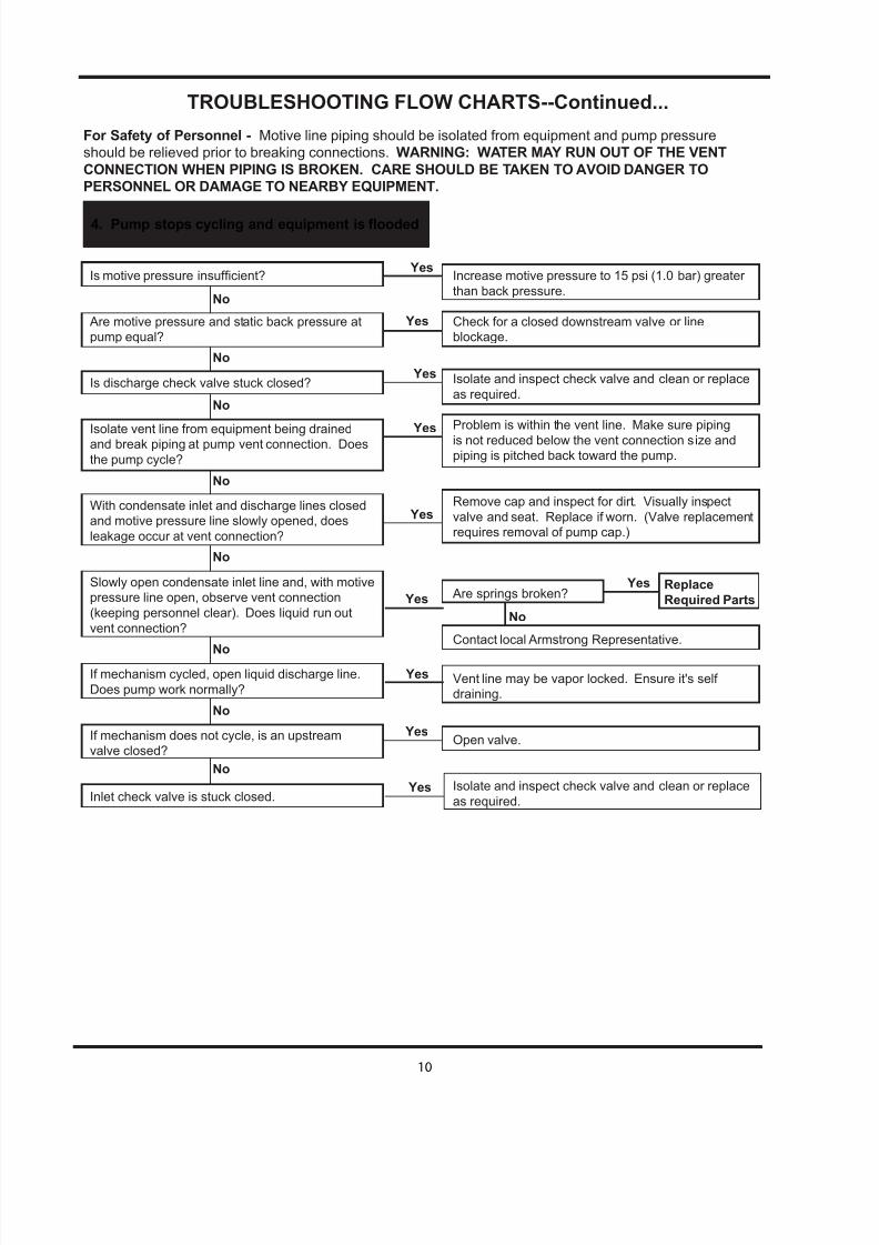
4. Pump stops cycling and equipment is ooded
TROUBLESHOOTING FLOW CHARTS--Continued...
For Safety of Personnel - Motive line piping should be isolated from equipment and pump pressure
should be relieved prior to breaking connections. WARNING: WATER MAY RUN OUT OF THE VENT
CONNECTION WHEN PIPING IS BROKEN. CARE SHOULD BE TAKEN TO AVOID DANGER TO
PERSONNEL OR DAMAGE TO NEARBY EQUIPMENT.
Is motive pressure insufcient?
Are motive pressure and static back pressure at
pump equal?
Is discharge check valve stuck closed?
Isolate vent line from equipment being drainedand break piping at pump vent connection. Does
the pump cycle?
With condensate inlet and discharge lines closed
and motive pressure line slowly opened, does
leakage occur at vent connection?
Slowly open condensate inlet line and, with motive
pressure line open, observe vent connection
(keeping personnel clear). Does liquid run out
vent connection?
If mechanism cycled, open liquid discharge line.
Does pump work normally?
If mechanism does not cycle, is an upstream
valve closed?
Inlet check valve is stuck closed.
Increase motive pressure to 15 psi (1.0 bar) greater
than back pressure.
Check for a closed downstream valve or line
blockage.
Isolate and inspect check valve and clean or replace
as required.
Problem is within the vent line. Make sure piping
is not reduced below the vent connection size and
piping is pitched back toward the pump.
Remove cap and inspect for dirt. Visually inspect
valve and seat. Replace if worn. (Valve replacement
requires removal of pump cap.)
Are springs broken?
Contact local Armstrong Representative.
Vent line may be vapor locked. Ensure it's self
draining.
Open valve.
Isolate and inspect check valve and clean or replace
as required.
No
No
No
No
No
No
No
No
Yes
Yes
Yes
Yes
Yes
Yes
Yes
Yes
YesReplace
Required Parts
No
Yes
7/21/2019 Armstrong Pump Trap
http://slidepdf.com/reader/full/armstrong-pump-trap 11/12
11
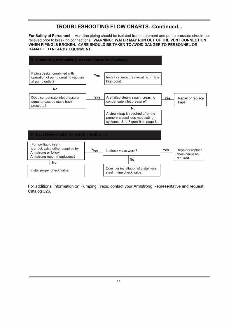
For additional information on Pumping Traps, contact your Armstrong Representative and request
Catalog 326.
TROUBLESHOOTING FLOW CHARTS--Continued...
For Safety of Personnel - Vent line piping should be isolated from equipment and pump pressure should be
relieved prior to breaking connections. WARNING: WATER MAY RUN OUT OF THE VENT CONNECTION
WHEN PIPING IS BROKEN. CARE SHOULD BE TAKEN TO AVOID DANGER TO PERSONNEL OR
DAMAGE TO NEARBY EQUIPMENT.
Yes Repair or replace
traps.
5. Chattering or knocking in return line after discharge
Piping design combined with
operation of pump creating vacuum
at pump outlet?
Does condensate inlet pressure
equal or exceed static back
pressure?
Yes
Yes
No
Is check valve worn?
Consider installation of a stainless
steel in-line check valve.
No
6. Excessive chatter from inlet check valve
(For low liquid inlet)
Is check valve either supplied by
Armstrong or follow
Armstrong recommendations?
Install proper check valve.
Install vacuum breaker at return line
high point.
Are failed steam traps increasing
condensate inlet pressure?
A steam trap is required after thepump in closed loop modulating
systems. See Figure 9 on page 8.
No
Repair or replace
check valve as
required.
No
Yes Yes

7/21/2019 Armstrong Pump Trap
http://slidepdf.com/reader/full/armstrong-pump-trap 12/12
Armstrong Condensate Management Group, 221 Armstrong Blvd., Three Rivers, MI 49093 -USA Ph: (269) 278-6500 Fax: (269) 279-3150
armstronginternational.comIB-108-B 9/09 Printed In U.S.A.
©2009 Armstrong International, Inc.
Designs and Materials are subject to change without notice.
Armstrong Fluid Handling, Inc.
Limited Warranty and Remedy
Armstrong Fluid Handling, Inc. (“Armstrong”) warrants to the original user of those products
supplied by it and used in the service and in the manner for which they are intended, that such products shall
be free from defects in material and workmanship for a period of one (1) year from the date of installation,
but not longer than 15 months from the date of shipment from the factory [unless a special warranty periodapplies as listed below]. This warranty does not extend to any product that has been subject to misuse, neglect
or alteration after shipment from the Armstrong factory. Except as may be expressly provided in a written
agreement between Armstrong and the user, which is signed by both parties, Armstrong DOES NOT MAKE
ANY OTHER REPRESENTATIONS OR WARRANTIES, EXPRESSED OR IMPLIED, INCLUDING,
BUT NOT LIMITED TO, ANY IMPLIED WARRANTY OF MERCHANTABILITY OR ANY IMPLIED
WARRANTY OF FITNESS FOR A PARTICULAR PURPOSE.
The sole and exclusive remedy with respect to the above limited warranty or with respect to any
other claim relating to the products or to defects or any condition or use of the products supplied by Armstrong,
however caused, and whether such claim is based upon warranty, contract, negligence, strict liability, or any other
basis or theory, is limited to Armstrong’s repair or replacement of the part or product, excluding any labor or anyother cost to remove or install said part or product, or at Armstrong’s option, to repayment of the purchase price.
As a condition of enforcing any rights or remedies relating to Armstrong products, notice of any warranty or
other claim relating to the products must be given in writing to Armstrong: (i) within 30 days of last day of the
applicable warranty period, or (ii) within 30 days of the date of the manifestation of the condition or occurrence
giving rise to the claim, whichever is earlier. IN NO EVENT SHALL ARMSTRONG BE LIABLE FOR
SPECIAL, DIRECT, INDIRECT, INCIDENTAL OR CONSEQUENTIAL DAMAGES, INCLUDING,
BUT NOT LIMITED TO, LOSS OF USE OR PROFITS OR INTERRUPTION OF BUSINESS. The
Limited Warranty and Remedy terms herein apply notwithstanding any contrary terms in any purchase order
or form submitted or issued by any user, purchaser, or third party and all such contrary terms shall be deemed
rejected by Armstrong.
Special Warranty Periods are as follows:Three (3) years after installation, but in no event longer than 39 months after shipment from
Armstrong's factory.
PT100, 200, 300, 3500 and 400 Series Standard Pumping Traps.
PT100, 200, 300, 3500 and 400 Series Replacement Cap Assemblies and Rescue Cap ®.