arm instruction sets & programs. 2 outline the arm processor arm instruction set summary
TRANSCRIPT

ARM Instruction Sets & ProgramsARM Instruction Sets & Programs

2
Outline
The ARM processorARM instruction setSummary

3
The ARM procssor

4
ARM Ltd ARM was originally developed at Acron Computer Limited, of
Cambridge, England between 1983 and 1985.– 1980, RISC concept at Stanford and Berkeley universities.– First RISC processor for commercial use
1990 Nov, ARM Ltd was founded ARM cores
– Licensed to partners who fabricate and sell to customers.
Technologies assist to design in the ARM application– Software tools, boards, debug hardware, application software, bus
architectures, peripherals etc…
Modification of the acronym expansion to Advanced RISC Machine.

5
RISC ArchitectureBerkeley incorporated a Reduced Instruction Set
Computer (RISC) architecture.It has the following key features:
– A fixed (32-bit) instruction size with few formats; • CISC processors typically had variable length instruction sets with
many formats.
– A load–store architecture where instructions that process data operate only on registers and are separate from instructions that access memory;
• CISC processors typically allowed values in memory to be used as operands in data processing instructions.
– A large register bank of thirty-two 32-bit registers, all of which could be used for any purpose, to allow the load-store architecture to operate efficiently;
• CISC register sets were getting larger, but none was this large and most had different registers for different purposes

6
RISC Organization
Hard-wired instruction decode logic– CISC processor used large microcode ROMs to decode
their instructions
Pipelined execution– CISC processors allowed little, if any, overlap between
consecutive instructions (though they do now)
Single-cycle execution– CISC processors typically took many clock cycles to
completes a single instruction
→ Simple is beauty
Compiler plays an important role

7
ARM Architecture vs. Berkeley RISC Features used
– Load/Store architecture– Fixed-length 32-bit instructions– 3-address instruction formats
function op 1 addr. op 2 addr. dest. addr.n bitsn bitsn bitsf bits
ADD d, S1, S2 ; d := S1 + S2
Features rejected– Register windows → costly
• Use shadow (banked) registers in ARM
– Delay branch• Badly with branch prediction
– Single-cycle execution of all instructions• Most single cycle, many other take multiple clock cycles

8
Data Size and Instruction Set
ARM processor is a 32-bit architectureWhen used in relation to the ARM
– Byte means 8 bits– Halfword means 16 bits (two bytes)– Word means 32 bits (four bytes)
Most ARM’s implement two instruction sets– 32-bit ARM instruction set– 16-bit Thumb instruction set

9
Data Types
ARM processor supports 6 data types– 8-bits signed and unsigned bytes– 16-bits signed and unsigned half-word, aligned on 2-byte
boundaries– 32-bits signed and unsigned words, aligned on 4-byte
boundaries
ARM instructions are all 32-bit words, word-alignedThumb instructions are half-words, aligned on 2-
byte boundaries

10
Processor Modes
The ARM has seven basic operating modes– User: unprivileged mode under which most tasks run– FIQ: entered when a high priority (fast) interrupts is raised– IRQ: entered when a low priority (normal) interrupts is
raised– Supervisor: entered on reset and when a software
interrupt instruction is executed– Abort: used to handle memory access violations– Undefined: used to handle undefined instructions– System: privileged mode using the same registers as
user mode• Not in ARM architecture 1, 2, or 3

11
Processor Modes (cont.)
Exception modes– FIQ, IRQ, Supervisor, Abort, and Undefined
Privileged modes– FIQ, IRQ, Supervisor, Abort, Undefined, and System

12
The Mode Bits
Mode changes by software control or external interrupts
13
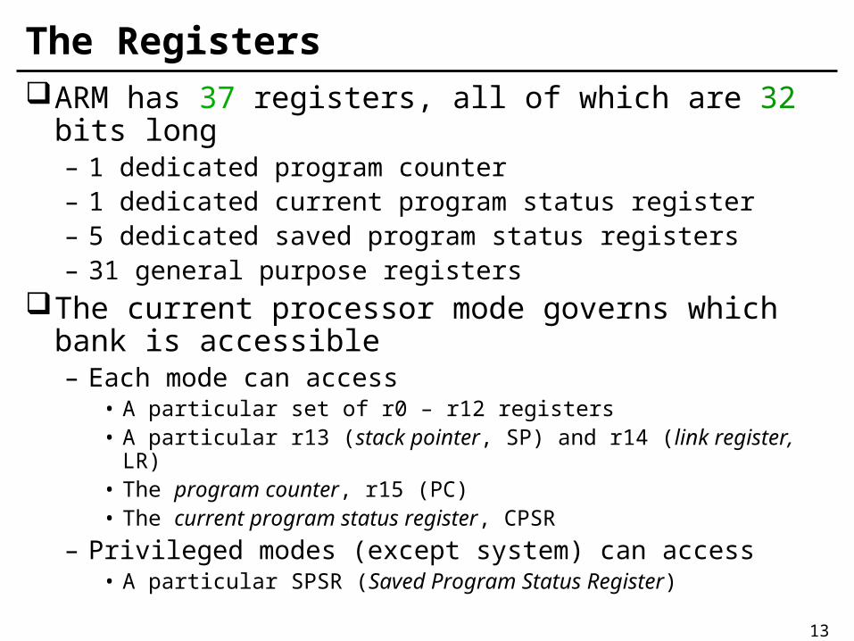
The RegistersARM has 37 registers, all of which are 32 bits long
– 1 dedicated program counter– 1 dedicated current program status register– 5 dedicated saved program status registers– 31 general purpose registers
The current processor mode governs which bank is accessible– Each mode can access
• A particular set of r0 – r12 registers• A particular r13 (stack pointer, SP) and r14 (link register, LR)• The program counter, r15 (PC)• The current program status register, CPSR
– Privileged modes (except system) can access• A particular SPSR (Saved Program Status Register)

14
Register Banking
r13_und
r14_und r14_irq
r13_irq
SPSR_und
r14_abt r14_svc
user modefiq
modesvc
modeabortmode
irqmode
undefinedmode
usable in user mode
exception modes only
r13_abt r13_svc
r8_fiq
r9_fiq
r10_fiq
r11_fiq
SPSR_irq SPSR_abt SPSR_svc SPSR_fiqCPSR
r14_fiq
r13_fiq
r12_fiq
r0
r1
r2
r3
r4
r5
r6
r7
r8
r9
r10
r11
r12
r13
r14
r15 (PC)
system mode
15
General Purpose Registers
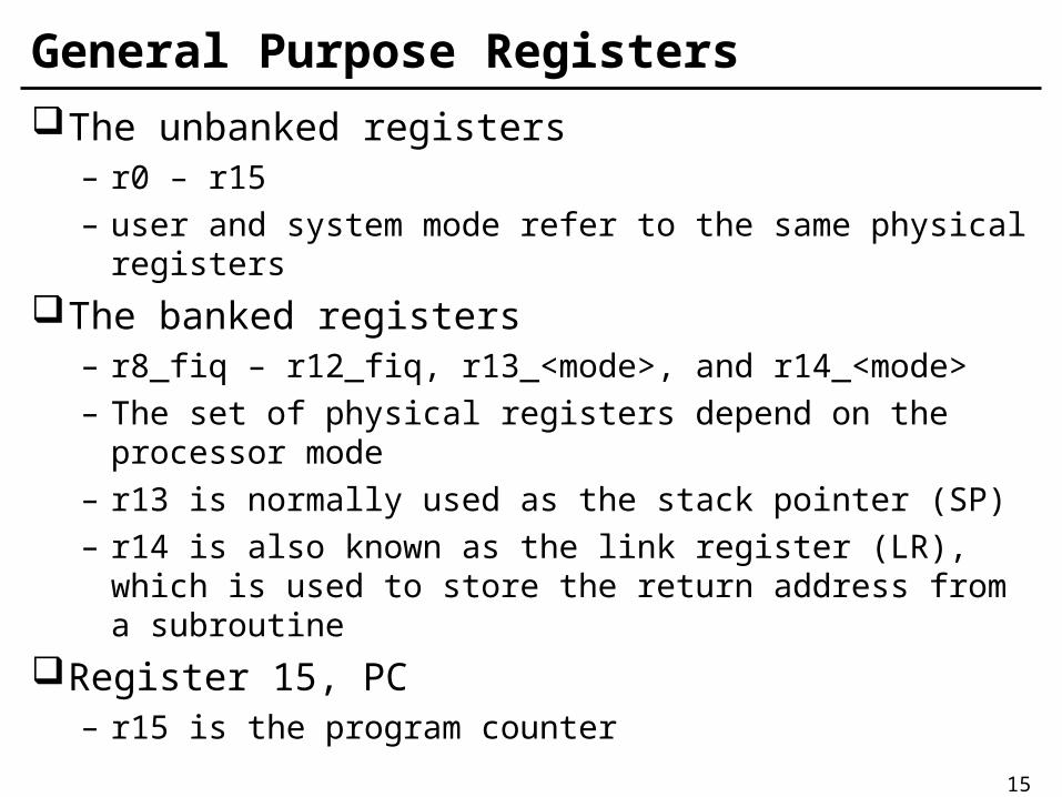
The unbanked registers– r0 – r15– user and system mode refer to the same physical
registers
The banked registers– r8_fiq – r12_fiq, r13_<mode>, and r14_<mode>– The set of physical registers depend on the processor
mode– r13 is normally used as the stack pointer (SP)– r14 is also known as the link register (LR), which is used
to store the return address from a subroutine
Register 15, PC– r15 is the program counter

16
Program Counter (r15)
When the processor is executing in ARM state:– All instructions are 32 bits wide– All instructions must be word-aligned– Therefore the PC value is stored in bits [32:2] with bits
[1:0] undefined (as instruction cannot be halfword)
When the processor is executing in Thumb state:– All instructions are 16 bits wide– All instructions must be halfword-aligned– Therefore the PC value is stored in bits [32:1] with bits [0]
undefined (as instruction cannot be byte-aligned)

17
Current Program Status Registers (CPSR)
Condition code flags– N: Negative result form ALU– Z: Zero result from ALU– C: ALU Operation Carried out– V: ALU operation oVerflowed
Sticky overflow flag – Q flag– Architecture 5TE only– Indicates if saturation has
occurred during certain operations
Interrupt disable bits– I = 1, disable the IRQ– F = 1, disable the FIQ
T Bit– Architecture xT only– T = 0, processor in ARM state– T = 1, processor in Thumb
state
Mode bits– Specify the processor mode

18
Saved Program Status Register (SPSR)Each privileged mode (except system mode) has
associated with it a SPSRThis SPSR is used to save the state of CPSR when
the privileged mode is entered in order that the user state can be fully restored when the user process is resumed
Often the SPSR may be untouched from the time the privileged mode is entered to the time it is used to restore the CPSR
If the privileged supervisor calls to itself the SPSR must be copied into a general register and saved

19
Exceptions
Exceptions are usually used to handle unexpected events which arise during the execution of a program, such as interrupts or memory faults, also cover software interrupts, undefined instruction traps, and the system reset
Three groups:– Exceptions generated as the direct effect of executing an
instruction• Software interrupts, undefined instructions, and prefetch abort
– Exceptions generated as a side effect of an instruction• Data aborts
– Exceptions generated externally• Reset, IRQ and FIQ
20
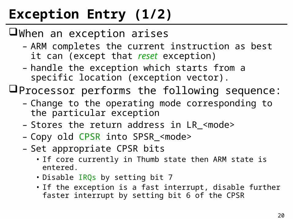
Exception Entry (1/2)When an exception arises
– ARM completes the current instruction as best it can (except that reset exception)
– handle the exception which starts from a specific location (exception vector).
Processor performs the following sequence:– Change to the operating mode corresponding to the
particular exception– Stores the return address in LR_<mode>– Copy old CPSR into SPSR_<mode>– Set appropriate CPSR bits
• If core currently in Thumb state then ARM state is entered.• Disable IRQs by setting bit 7• If the exception is a fast interrupt, disable further faster interrupt
by setting bit 6 of the CPSR
21
Exception Entry (2/2)
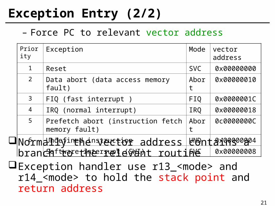
– Force PC to relevant vector address
Normally the vector address contains a branch to the relevant routine
Exception handler use r13_<mode> and r14_<mode> to hold the stack point and return address
Priority Exception Mode vector address
1 Reset SVC 0x00000000
2 Data abort (data access memory fault) Abort 0x00000010
3 FIQ (fast interrupt ) FIQ 0x0000001C
4 IRQ (normal interrupt) IRQ 0x00000018
5 Prefetch abort (instruction fetch memory fault)
Abort 0c0000000C
6 Undefined instruction UND 0x00000004
Software interrupt (SWI) SVC 0x00000008

22
Exception Return
Once the exception has been handled, the user task is normally resumed
The sequence is – Any modified user registers must be restored from the
handler’s stack– CPSR must be restored from the appropriate SPSR– PC must be changed back to the relevant instruction
address
The last two steps happen atomically as part of a single instruction

23
Memory Organization
Word, half-word alignment (xxxx00 or xxxxx0)ARM can be set up to access data in either little-
endian or big-endian format, through they default to little-endian.

24
Features of the ARM Instruction Set
Load-store architecture– Process values which are in registers– Load, store instructions for memory data accesses
3-address data processing instructionsConditional execution of every instructionLoad and store multiple registersShift, ALU operation in a single instructionOpen instruction set extension through the
coprocessor instructionVery dense 16-bit compressed instruction set
(Thumb)

25
Coprocessors
– Up to 16 coprocessors can be defined– Expands the ARM instruction set– Each coprocessor can have up to 16 private registers of
any reasonable size– Load-store architecture

26
Thumb
Thumb is a 16-bit instruction set– Optimized for code density from C code– Improved performance form narrow memory– Subset of the functionality of the ARM instruction set
Core has two execution states – ARM and Thumb– Switch between them using BX instruction
Thumb has characteristic features:– Most Thumb instructions are executed unconditionally– Many Thumb data process instruction use a 2-address
format– Thumb instruction formats are less regular than ARM
instruction formats, as a result of the dense encoding.

27
I/O System
ARM handles input/output peripherals as memory-mapped with interrupt support
Internal registers in I/O devices as addressable locations with ARM’s memory map read and written using load-store instructions
Interrupt by normal interrupt (IRQ) or fast interrupt (FIQ)
Interrupt input signals are level-sensitive and maskable
May include Direct Memory Access (DMA) hardware

28
ARM Architecture Version (1/5)
Version 1– The first ARM processor, developed at Acorn Computers
Limited 1983-1985– 26-bit address, no multiply or coprocessor support
Version 2– Sold in volume in the Acorn Archimedes and A3000
products– 26-bit addressing, including 32-bit result multiply and
coprocessor
Version 2a– Coprocessor 15 as the system control coprocessor to
manage cache– Add the atomic load store (SWP) instruction
29
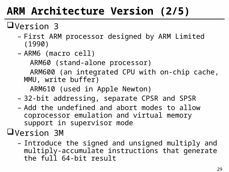
ARM Architecture Version (2/5)Version 3
– First ARM processor designed by ARM Limited (1990)– ARM6 (macro cell) ARM60 (stand-alone processor) ARM600 (an integrated CPU with on-chip cache, MMU,
write buffer) ARM610 (used in Apple Newton)– 32-bit addressing, separate CPSR and SPSR– Add the undefined and abort modes to allow coprocessor
emulation and virtual memory support in supervisor modeVersion 3M
– Introduce the signed and unsigned multiply and multiply-accumulate instructions that generate the full 64-bit result

30
ARM Architecture Version (3/5)
Version 4– Add the signed, unsigned half-word and signed byte load
and store instructions– Reserve some of SWI space for architecturally defined
operation– System mode is introduced
Version 4T– 16-bit Thumb compressed form of the instruction set is
introduced

31
ARM Architecture Version (4/5)
Version 5T– Introduced recently, a superset of version 4T adding the
BLX, CLZ and BRK instructions
Version 5TE– Add the signal processing instruction set extension
Version 5TEJ– Introduced Jazelle technology for Java which provides
significantly higher performance than a software-based Java Virtual Machine (JVM).

32
ARM Architecture Version (5/5)
Version 6– Announced in 2001– Features SIMD (Single Instruction Multiple Data)
extensions – Offering the low power consumption

33
ARM Architecture Version SummaryCore Version Feature
ARM1 v1 26 bit address
ARM2, ARM2as, ARM3 v2 32 bit multiply coprocessor
ARM6, ARM60, ARM610,
ARM7, ARM710,
ARM7D, ARM7DI
v3 32 bit addressesSeparate PC and PSRsUndefined instruction and Abort modesFully staticBig or little endian
StrongARM, SA-110, SA-1100
ARM8, ARM810
v4 Half word and signed halfword/byte supportEnhanced multiplierSystem mode
ARM7TDMI, ARM710T, ARM720T, ARM740T
ARM9TDMI, ARM920T, ARM940T
v4T Thumb instruction set
T: Thumb instruction set
M: enhanced Multiplier
D: On-chip Debug
I: Embedded ICE Logic
34
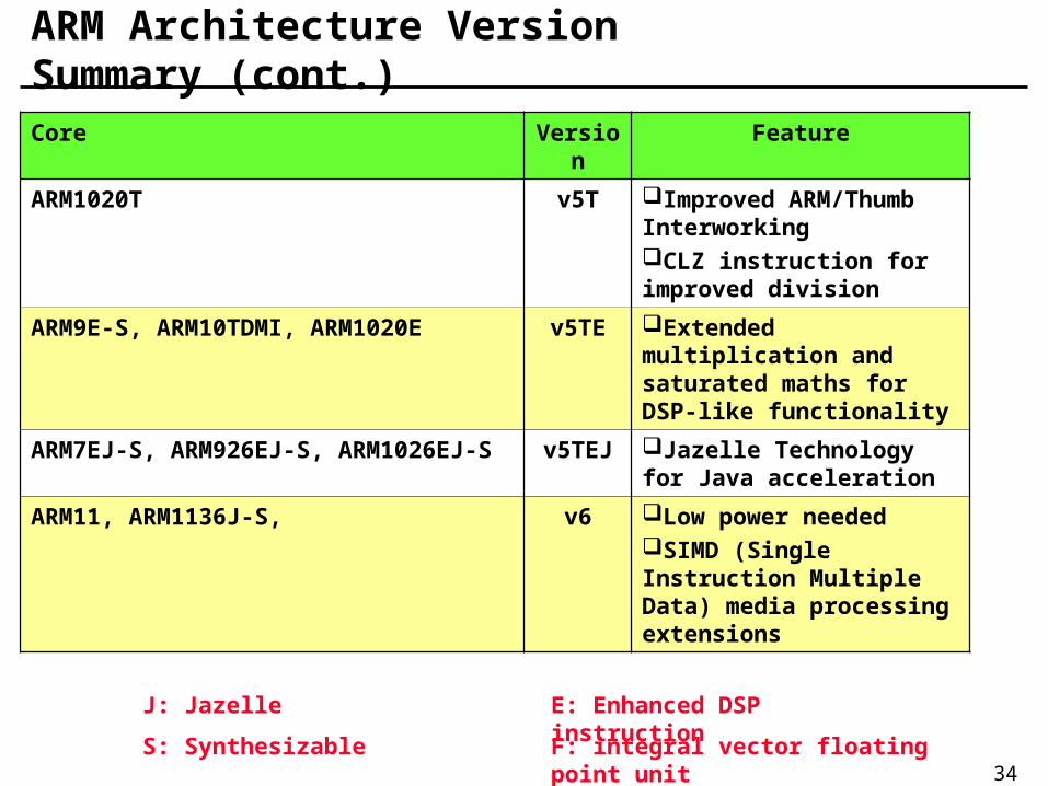
ARM Architecture Version Summary (cont.)Core Version Feature
ARM1020T v5T Improved ARM/Thumb InterworkingCLZ instruction for improved division
ARM9E-S, ARM10TDMI, ARM1020E v5TE Extended multiplication and saturated maths for DSP-like functionality
ARM7EJ-S, ARM926EJ-S, ARM1026EJ-S v5TEJ Jazelle Technology for Java acceleration
ARM11, ARM1136J-S, v6 Low power neededSIMD (Single Instruction Multiple Data) media processing extensions
J: Jazelle
S: Synthesizable F: integral vector floating point unit
E: Enhanced DSP instruction

35
ARM instruction set

36
ARM assembly language program– ARM development board or ARM emulator
ARM instruction set– Standard ARM instruction set– A compressed form of the instruction set, a subset of the
full ARM instruction set is encoded into 16-bit instructions – Thumb instruction
– Some ARM cores support instruction set extensions to enhance signal processing capabilities

37
Instructions
Data processing instructionsData transfer instructionsControl flow instructions
38
Conditional ExecutionMost instruction sets only allow branches to be
executed conditionally.However by reusing the condition evaluation
hardware, ARM effectively increase number of instruction– All instructions contain a condition field which determines
whether the CPU will execute them– Non-executed instruction still take up 1 cycle
• To allow other stages in the pipeline to complete
This reduces the number of branches which would stall the pipeline– Allows very dense in-line code– The time penalty of not executing several conditional
instructions is frequently less than overhead of the branch or instruction call that would otherwise be needed

39
Condition code
Opcode
[31:28]
Mnemonic
extension Interpretation Status flag state for execution
0000 EQ Equal / equals zero Z set
0001 NE Not equal Z clear
0010 CS/HS Carry set / unsigned higher or some C set
0011 CC/LO Carry clear / unsigned lower C clear
0100 MI Minus / negative N set
0101 PL Plus / positive or zero N clear
0110 VS Overflow V set
0111 VC No overflow V clear
1000 HI Unsigned higher C set and Z clear
1001 LS Unsigned lower or same C clear or Z set
1010 GE Signed greater than or equal N equals V
1011 LT Signed less than N is not equal to V
1100 GT Signed greater than Z clear and N equals V
1101 LE Signed less than or equal Z sets or N is not equal to V
1110 AL Always any
1111 NV Never (do not use!) none
cond
0272831

40
Example of Conditional Execution An unusual feature of the ARM instruction set is that
conditional execution applies not only to branches but to all ARM instructions
Whenever the conditional sequence is 3 instructions or fewer it is better (smaller and faster) to exploit conditional execution than to use a branch
CMP r0,#5
BEQ Bypass ;if (r0!=5)
ADD r1,r1,r0 ;{r1=r1+r0}
SUB r1,r1,r2
Bypass …
CMP r0,#5
ADDNE r1,r1,r0
SUBNE r1,r1,r2
if((a==b)&&(c==d)) e++;
CMP r0,r1
CMPEQ r2,r3
ADDEQ r4,r4,#1

41
Using and Updating the condition Field To execute an instruction conditionally, simply postfix it with
the appropriate condition:– For example an add instruction takes the form
• ADD r0, r1, r2 ; r0 = r1 + r2 (ADDAL)
– To execute this only if the zero flag is set• ADDEQ r0, r1, r2 ; r0 = r1 + r2 iff zero flag set
By default, data processing operations do not affect the condition flags– With comparison instructions this is the only effect
To cause the condition flags to be updated, the S bit of the instruction needs to be set by postfixing the instruction (and any condition codes) with an “S”.– For example to add two numbers and set the condition flags:
• ADDS r0, r1, r2 ; r0 = r1 + r2 and set flags

42
Data Processing Instruction (1/3) Consist of
– Arithmetic (ADD, SUB, RSB)– Logical (BIC, AND)– Compare (CMP, TST)– Register movement (MOV, MVN)
All operands are 32-bit wide; come from registers or specified as literal in the instruction itself
Second operand sent to ALU via barrel shifter 32-bit result placed in register; long multiply instruction
produces 64-bit result 3-address instruction format
– 2 source operands and 1 destination register– One source is always a register, the second may be a register, a
shifted register or an immediate value

43
Data Processing Instruction (2/3) Allows direct control of whether or not the condition codes
are affected by S bit (condition code unchanged when S = 0)– N = 1 if the result is negative; 0 otherwise (i.e. N = bit 31 of the result)– Z = 1 if the result is zero; 0 otherwise– C = 1 carry out from the ALU when ADD, ADC, SUB, SBC, RSB,
RSC, CMP, or CMN; carry out from the shifter– V = 1 if overflow from bit 30 to bit 31; 0 if no overflow (V is preserved in non-arithmetic operations)
PC may be used as a source operand (address of the instruction plus 8) except when a register-specified shift amount is used
PC may be specified as the destination register, the instruction is a form of branch (return from a subroutine)

44
Data Processing Instruction (3/3)
cond 0 0 operand 2# opcode S Rn Rd
31 28 27 26 25 24 21 20 19 16 15 12 11 0
destination register
first operand register
set condition codes
arithmetic/logic function
8-bit immediate1
25 11 8 7 0
#rot
Rm
11 7 6 5 4 3 0
#shift
Rm
0
25
11 8 7 6 5 4 3 0
Rs
Sh 0
10 Sh
immediate alignment
immediate shift length
shift type
second operand register
register shift length

45
Simple Register Operands (1/2)Arithmetic Operations
ADD r0,r1,r2 ;r0:=r1+r2ADC r0,r1,r2 ;r0:=r1+r2+CSUB r0,r1,r2 ;r0:=r1–r2SBC r0,r1,r2 ;r0:=r1–r2+C–1RSB r0,r1,r2 ;r0:=r2–r1, reverse subtractionRSC r0,r1,r2 ;r0:=r2–r1+C–1
– By default data processing operations do no affect the condition flags
Bit-wise Logical OperationsAND r0,r1,r2 ;r0:=r1ANDr2ORR r0,r1,r2 ;r0:=r1ORr2EOR r0,r1,r2 ;r0:=r1XORr2BIC r0,r1,r2 ;r0:=r1AND(NOT r2), bit clear

46
Simple Register Operands (2/2)
Register Movement Operations– Omit 1st source operand from the format
MOV r0,r2 ;r0:=r2
MVN r0,r2 ;r0:=NOT r2, move 1’s complement
Comparison Operations– Not produce result; omit the destination from the format– Just set the condition code bits (N, Z, C and V) in CPSR
CMP r1,r2 ;set cc on r1 - r2, compare
CMN r1,r2 ;set cc on r1 + r2, compare negated
TST r1,r2 ;set cc on r1 AND r2, bit test
TEQ r1,r2 ;set cc on r1 XOR r2, test equal

47
Immediate Operands
Replace the second source operand with an immediate operand, which is a literal constant, preceded by “#”
ADD r3,r3,#1 ;r3:=r3+1
AND r8,r7,#&FF ;r8:=r7[7:0], &:hexadecimal
Since the immediate value is coded within the 32 bits of the instruction, it is not possible to enter every possible 32-bit value as an immediate.
Immediate = (0 → 255) × 22n where 0 12n
48
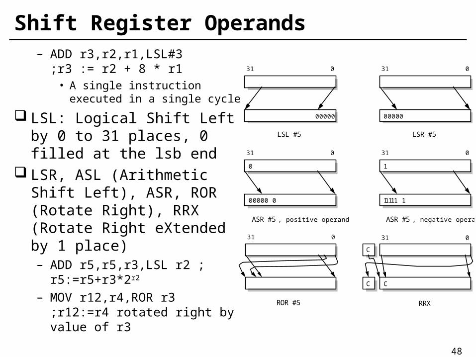
Shift Register Operands– ADD r3,r2,r1,LSL#3 ;r3 := r2 + 8 * r1
• A single instruction executed in a single cycle
LSL: Logical Shift Left by 0 to 31 places, 0 filled at the lsb end
LSR, ASL (Arithmetic Shift Left), ASR, ROR (Rotate Right), RRX (Rotate Right eXtended by 1 place)– ADD r5,r5,r3,LSL r2 ; r5:=r5+r3*2r2
– MOV r12,r4,ROR r3;r12:=r4 rotated right by value of r3
031
00000
LSL #5
031
00000
LSR #5
031
11111 1
ASR #5 , negative operand
031
00000 0
ASR #5 , positive operand
0 1
031
ROR #5
031
RRX
C
C C
49
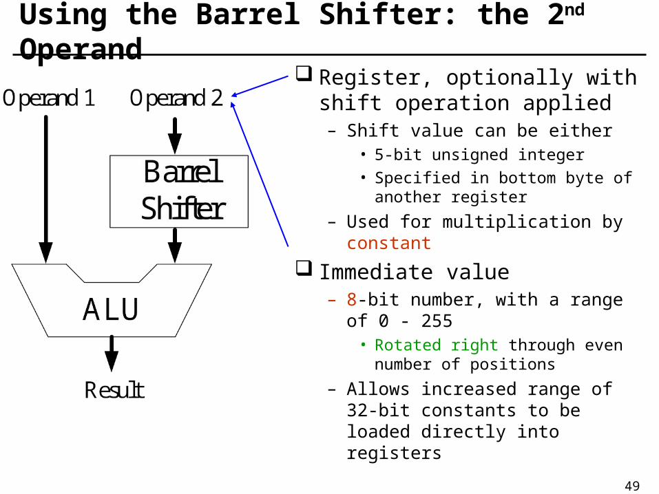
Using the Barrel Shifter: the 2nd Operand Register, optionally with shift
operation applied– Shift value can be either
• 5-bit unsigned integer
• Specified in bottom byte of another register
– Used for multiplication by constant
Immediate value– 8-bit number, with a range of 0 -
255• Rotated right through even number
of positions
– Allows increased range of 32-bit constants to be loaded directly into registers

50
Multiply Instructions (1/2)
32-bit product (Least Significant)– MUL{<cond>}{S} Rd,Rm,Rs– MLA{<cond>}{S} Rd,Rm,Rs,Rn
MUL r4,r3,r2; r4:=(r3*r2)[31:0]
MLA r4,r3,r2,r1; r4:=(r3*r2+r1)[31:0]
64-bit Product– <mul>{<cond>}{S} RdHi,RdLo,Rm,Rs– <mul> is UMULL,UMLAL,SMULL,SMLAL

51
Multiply Instructions (2/2)
Booth’s algorithm is used to perform integer multiplication– Instructions will early terminate wherever possible– On ARM7TDMI Mul will execute in minimum of 2 clock
cycles and maximum of 5 clock cycles
Restrictions on use:– Rd and Rm cannot be the same register (can be avoided
by swapping over Rm and Rs – multiplication is commutative)

52
Multiplication by a ConstantMultiplication by a constant equals to a ((power of 2)
+/- 1) can be done in a single cycle– Using MOV, ADD or RSB with an inline shift
Example: r0 = r1 * 5Example: r0 = r1 + (r1 * 4)
– ADD r0,r1,r1,LSL #2 ;r0:=r1+r1*4Can combine several instruction to carry out other
multipliesExample: r2 = r3 * 119Example: r2 = r3 * 17 * 7Example: r2 = r3 * (16 + 1) * (8 - 1)
– ADD r2,r3,r3,LSL #4 ;r2:=r3*17– RSB r2,r2,r2,LSL #3 ;r2:=r2*7

53
Loading Constants (1/2) No single ARM instruction can load a 32-bit immediate
constant directly into a register– All ARM instructions are 32-bit long– ARM instructions do not use the instruction stream as data
The data processing instruction format has 12 bits available for operand 2 (refer to P.44)– If used directly, this would only give a range of 4096
Instead it is used to store 8-bit constants, give a range of 0-255
These 8 bits can then be rotated right through an even number of positions
This gives a much larger range of constants that can be directly loaded, through some constants will still need to be loaded from memory

54
Loading Constant (2/2)
To load a constant, simply move the required value into a register – the assembler will convert to the rotate form for us– MOV r0,#4096 ;MOV r0,#&1000 (0x40 ror 26)
The bitwise complements can also be formed using MVN:– MOV r0,#&FFFFFFFF ;MVN r0,#0
Value that cannot be generated in this way will cause an error

55
Loading 32-bit Constants To allow larger constants to be loaded, the assembler offers
a pseudo-instruction:– LDR Rd,=const
This will either:– Produce a MOV or MVN instruction to generate the value (if possible)
or– Generate a LDR instruction with a PC-relative address to read the
constant from a literal pool (constant data area embedded in the code)
For example– MOV r0,=&FF ;MOV r0,#0xFF– LDR r0,=&55555555 ;LDR r0,[PC,#Imm10]
As this mechanism will always generate the best instruction for a given case, it is the recommended way of loading constant

56
Data Transfer Instructions
Three basic forms to move data between ARM registers and memory– Single register load and store instruction
• A byte, a 16-bit half word, a 32-bit word
– Multiple register load and store instruction• To save or restore workspace registers for procedure entry and
exit• To copy blocks of data
– Single register swap instruction• A value in a register to be exchanged with a value in memory• To implement semaphores to ensure mutual exclusion on
accesses

57
Single Register Data Transfer
Word transfer– LDR / STR
Byte transfer– LDRB / STRB
Halfword transfer– LDRH / STRH
Load singled byte or halfword-load value and sign extended to 32 bits– LDRSB / LDRSH
All of these can be conditionally executed by insert-ing the appropriate condition code after STR/LDR– LDREQB

58
Addressing mode
Register-indirect addressingBase-plus-offset addressing
– Base register• r0 – r15
– Offset, and or subtract an unsigned number• Immediate• Register (not PC)• Scaled register (only available for word and unsigned byte
instructions)
Stack addressingBlock-copy addressing

59
Register-Indirect Addressing
Use a value in one register (base register) as a memory addressLDR r0,[r1] ;r0:=mem32[r1]
STR r0,[r1] ;mem32[r1]:=r0
Other forms– Adding immediate or register offsets to the base address

60
Initializing an Address Pointer
A small offset to the program counter, r15– ARM assembler has a “pseudo” instruction, ADR
As an example, a program which must copy data from TABLE1 to TABLE2, both of which are near to the code
Copy ADR r1,TABLE1 ;r1 points to TABLE1
ADR r2,TABLE2 ;r2 points to TABLE2
…
TABLE1
… ;<source>
TABLE2
… ;<destination>

61
Base-plus-offset Addressing (1/2)
Pre-indexingLDR r0,[r1,#4] ;r0:=mem32[r1+4]
– Offset up to 4K, added or subtracted, (# -4)
Post-indexingLDR r0,[r1],#4 ;r0:=mem32[r1], r1:=r1+4
– Equivalent to a simple register-indirect load, but faster, less code space
Auto-indexingLDR r0, [r1,#4]! ;r0:=mem32[r1+4], r1:=r1+4
– No extra time, auto-indexing performed while the data is being fetched from memory

62
Base-plus-offset Addressing (2/2)

63
Multiple Register Data Transfer (1/2) The load and store multiple instructions (LDM/STM) allow
between 1 and 16 registers to be transferred to or from memory– Order of register transfer cannot be specified, order in the list is
insignificant– Lowest register number is always transferred to/from lowest memory
location accessed The transferred registers can be either
– Any subset of the current bank of registers (default)– Any subset of the user mode bank of registers when in a privileged
mode (postfix instruction with a “^”) Base register used to determine where memory access
should occur– 4 different addressing modes– Base register can be optionally updated following the transfer (using
“!”)

64
Multiple Register Data Transfer (2/2) These instruction are very efficient for
– Moving block of data around memory– Saving and restoring context – stack
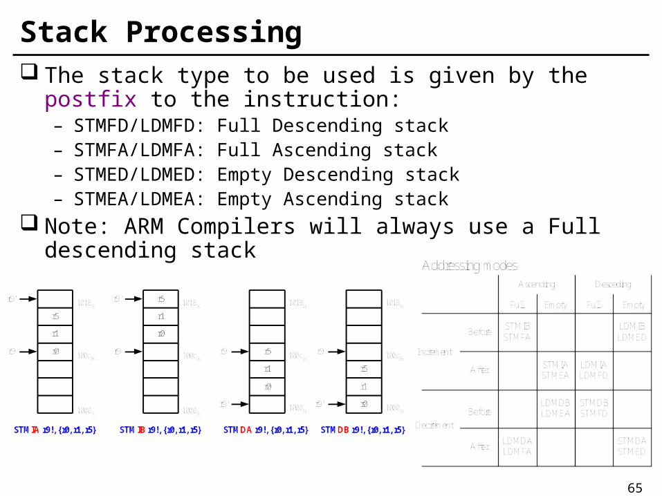
The direction that the base pointer moves through memory is given by the postfix to the STM/LDM instruction– STMIA/LDMIA: Increment After– STMIB/LDMIB: Increment Before– STMDA/LDMDA: Decrement After– STMDB/LDMDB: Decrement Before
Allow any subset (or all, r0 to r15) of the 16 registers to be transferred with a single instruction
LDMIA r1,{r0,r2,r5} ;r0:=mem32[r1]
;r2:=mem32[r1+4]
;r5:=mem32[r1+8]
65
Stack Processing The stack type to be used is given by the postfix to the
instruction:– STMFD/LDMFD: Full Descending stack– STMFA/LDMFA: Full Ascending stack– STMED/LDMED: Empty Descending stack– STMEA/LDMEA: Empty Ascending stack
Note: ARM Compilers will always use a Full descending stack

66
Swap Memory and Register Instructions
Syntax– SWP{<cond>}{B} Rd,Rm,[Rn]– Rd <- [Rn], [Rn] <- Rm
Combine a load and a store of a word or an unsigned byte in a single instruction
ExampleADR r0,SEMAPHORE
SWPB r1,r1,[r0] ;exchange byte
67
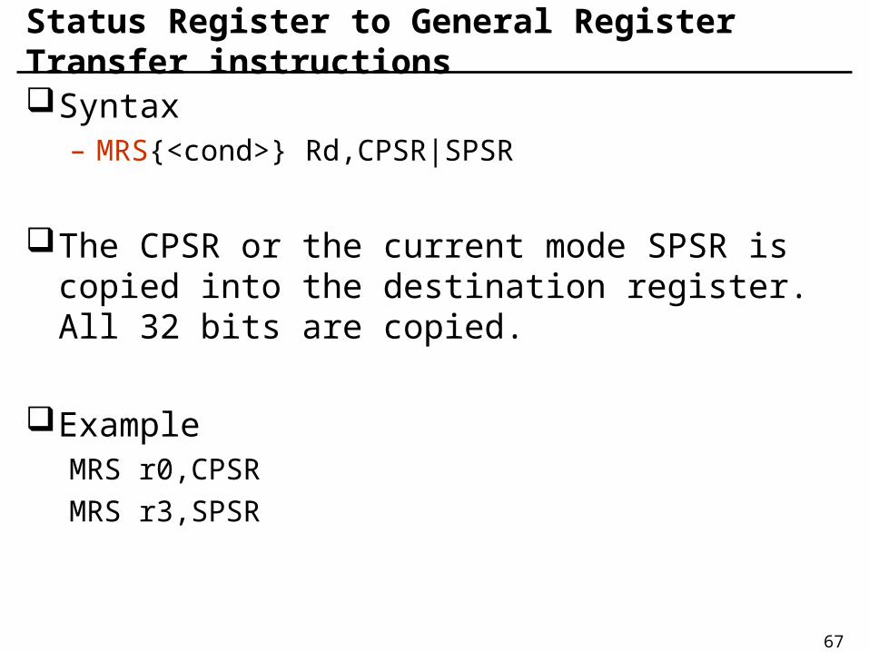
Status Register to General Register Transfer instructionsSyntax
– MRS{<cond>} Rd,CPSR|SPSR
The CPSR or the current mode SPSR is copied into the destination register. All 32 bits are copied.
ExampleMRS r0,CPSR
MRS r3,SPSR

68
General Register to Status Register Transfer instructionsSyntax
– MSR{<cond>} CPSR_<field>|SPSR_<field>,#<32-bit immediate>
– MSR{<cond>} CPSR_<field>|SPSR_<field>,Rm– <field> is one of
• c – the control field PSR[7:0]• x – the extension field PSR[15:8]• s – the status field PSR[23:16]• f – the flag field PSR[31:24]
Example– Set N, X, C, V flags
• MSR CPSR_f, #&f0000000
69
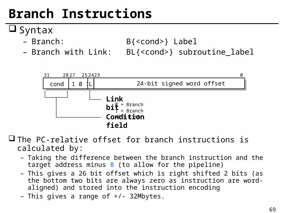
Branch Instructions Syntax
– Branch: B{<cond>} Label– Branch with Link: BL{<cond>} subroutine_label
The PC-relative offset for branch instructions is calculated by:– Taking the difference between the branch instruction and the target
address minus 8 (to allow for the pipeline)– This gives a 26 bit offset which is right shifted 2 bits (as the bottom two
bits are always zero as instruction are word-aligned) and stored into the instruction encoding
– This gives a range of +/- 32Mbytes.
cond 1 0 1 L 24-bit signed word offset
31 28 27 25 24 23 0
Link bit0 = Branch1 = Branch with Link
Condition field

70
Conditional Branch (1/2)
The branch has a condition associated with it and it is only executed if the condition codes have the correct value – taken or not taken
MOV r0,#0 ;initialize counter
Loop …
ADD r0,r0,#1 ;increment loop counter
CMP r0,#10 ;compare with limit
BNE Loop ;repeat if not equal
;else fail through

71
Conditional Branch (2/2)

72
Examples
Unconditional jumpB LABEL
…
LABEL …
Loop ten timesMOV r0,#10
Loop …
SUBS r0,#1
BNE Loop
…
Conditional subroutine call
CMP r0,#5
BLLT SUB1 ;if r0<5,
;call sub1
BLGE SUB2 ;else call
;SUB2
Call a subroutineBL SUB
…
SUB …
MOV PC,r14

73
Branch, Branch with Link and eXchangeB{L}X{<cond>} Rm
– The branch target is specified in a register, Rm– Bit[0] of Rm is copied into the T bit in CPSR; bit[31:1] is
moved into PC– If Rm[0] is 1, the processor switches to execute Thumb
instructions and begins executing at the address in Rm aligned to a half-word boundary by clearing the bottom bit
– If Rm[0] is 0, the processor continues executing ARM instructions and begins executing at the address in Rm aligned to a word boundary by clearing Rm[1]
BLX <target address>– Call Thumb subroutine from ARM– The H bit (bit 24) is also added into bit 1 of the resulting
addressing, allowing an odd half-word address to be selected for the target instruction which will always be a Thumb instruction
74
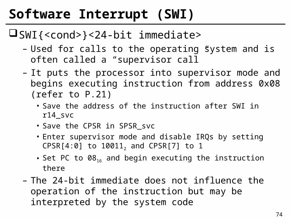
Software Interrupt (SWI)
SWI{<cond>}<24-bit immediate>– Used for calls to the operating system and is often called
a “supervisor call”– It puts the processor into supervisor mode and begins
executing instruction from address 0x08 (refer to P.21)• Save the address of the instruction after SWI in r14_svc• Save the CPSR in SPSR_svc• Enter supervisor mode and disable IRQs by setting CPSR[4:0] to
100112 and CPSR[7] to 1
• Set PC to 0816 and begin executing the instruction there
– The 24-bit immediate does not influence the operation of the instruction but may be interpreted by the system code

75
Supervisor Calls
The supervisor is a program which operates at a privileged level, which means that it can do things that a use-level program cannot do directly (e.g. input or output)
SWI instruction– Software interrupt or supervisor call
SWI SWI_WriteC ;output r0[7:0]
SWI SWI_Exit ;return to monitor program

76
Coprocessor InstructionsThe ARM architecture supports 16 coprocessorsThe instructions for each coprocessor occupy a
fixed part of the ARM instruction set– If the appropriate coprocessor is not present in the
system, an undefined instruction exception occurs.There are three types of coprocessor instruction
– Coprocessor data processing• CDP: Initiate a coprocessor data processing operation
– Coprocessor register transfers• MRC: Move to ARM register from coprocessor register• MCR: Move to Coprocessor register from ARM register
– Coprocessor memory transfers• LDC: Load coprocessor register from memory• STC: Store from coprocessor register to memory
77
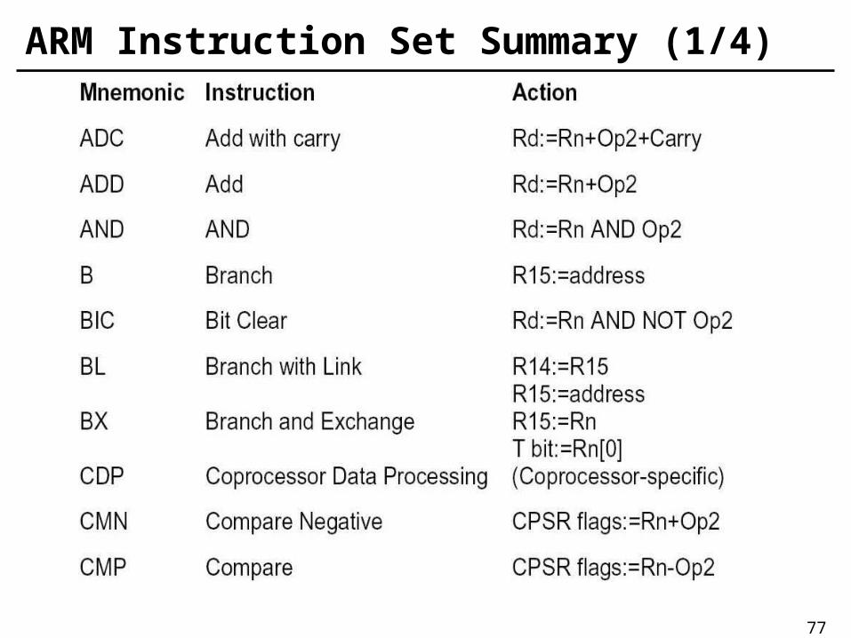
ARM Instruction Set Summary (1/4)

78
ARM Instruction Set Summary (2/4)

79
ARM Instruction Set Summary (3/4)

80
ARM Instruction Set Summary (4/4)

81
ARM Instruction Set Format

82
Summary ARM architecture
– Load/Store architecture– Fixed-length 32-bit
architecture– 3-address instruction formats– 37 registers– Little endian/big endian– Memory maped IO– Coprocessors
Instruction set – Conditional execution– 32-bit ARM instruction
• Data processing instructions– Arithmetic/Logical/
Compare/Multiply
• Data transfer instructions– Load/Store/Swap
• Control flow instructions– Branch/SWI
– 16-bit Thumb instruction (next class)