arlington high schoolparklex, prodema, approved equal. o multiple colors, textures, and patterns in...
TRANSCRIPT

Arlington High SchoolARLINGTON , M A
P R O J ECT M A N UA L 2 20 2019


PROJECT MANUAL
ARLINGTON HIGH SCHOOL Arlington, MA
HMFH Architects, Inc.
130 Bishop Allen Drive
Cambridge, MA 02139
617 492 2200
SCHEMATIC DESIGN MSBA Submission VOLUME 1 OF 1
February 20, 2019
SET#_______


HMFH PROJECT #408417 ARLINGTON HIGH SCHOOL ARLINGTON, MA
FEBRUARY 7, 2019 TABLE OF CONTENTS 000110 - 1
DOCUMENT 000110
TABLE OF CONTENTS
PART 1 - GENERAL DOCUMENTS
Document:
000110 Table of Contents Pages: 1-2 000120 Outline Specification Pages: 1-13
PART 2 - ENGINEERING, SITE WORK, AND SUPPLEMENTAL DOCUMENTS
DIVISION 03 THROUGH DIVISION 05
Document:
Schematic Design Structural Narrative Pages: 1-13
DIVISION 11
Document:
Schematic Design Food Service Narrative Pages: 1-08
DIVISION 21 FIRE PROTECTION
Document:
Fire Protection Systems Narrative Pages: 1-03
DIVISION 22 PLUMBING
Document:
Plumbing Systems Narrative Pages: 1-04 Preliminary Life-Cycle Cost Estimate (MGL Chapter 149 Section 44M) Pages: 1-07
DIVISION 23 HEATING VENTILATING AND AIR CONDITIONING
Document:
HVAC Systems Narrative Pages: 1-07 Preliminary Life-Cycle Cost Estimate (MGL Chapter 149 Section 44M) Pages: 1-07
DIVISION 26: ELECTRICAL
Document:
Electrical Systems Narrative Pages: 1-09 Audiovisual and Theatrical Systems Narrative Pages: 1-08
DIVISION 27 AND 28: COMMUNICATIONS AND SECURITY
Document:
Technology, Communications, AV and Security Systems Narrative Pages: 1-10

HMFH PROJECT #408417 ARLINGTON HIGH SCHOOL ARLINGTON, MA
FEBRUARY 7, 2019 TABLE OF CONTENTS 000110 - 2
DIVISION 31: EARTHWORK
Document:
Section Refer to Schematic Design Binder: Preliminary Geotechnical Engineering Report
DIVISION 32: SITE IMPROVEMENTS
Document:
Landscape Narrative Pages: 1-02
DIVISION 33: UTILITIES
Document:
Civil Narrative Pages: 1-22
APPENDICES
Document:
1. Phasing Diagrams Pages: 1-26 2. Utility Co. Accelerate Performance Program Pages: 1-05 3. Preliminary SD Energy Model Study Pages: 1-17 4. Proprietary Items Pages: 1-01 5. Schematic Design Room Finishes Schedule Pages: 1-07 6. Salvage Items Photographs Pages: 1-09
END OF TABLE OF CONTENTS

HMFH PROJECT #408417 ARLINGTON HIGH SCHOOL ARLINGTON, MA
FEBRUARY 13, 2019 OUTLINE SPECIFICATION 000120-1
DOCUMENT 000120
OUTLINE SPECIFICATION
SCHEMATIC PHASE- CONSTRUCTION ASSEMBLIES AND SYSTEMS
PROJECT DESCRIPTION
10: GENERAL
1010 – Project Summary
• New construction of the Arlington High School in Arlington, MA.
• Phased construction/demolition while existing building is occupied. Refer to Phasing Diagrams - Appendix 1.
• Phasing/Occupancy: Phasing will be required to allow for Owner occupancy during construction. Temporary interior and exterior partitions, finishes, MEP/FP, reconfiguration of selected areas in existing builkding, temporary egress and covered walkways, temporary bridging, temporary stairs, temporary parking, temporary mechanical and utility tie-ins and connections, dust and noise control, barriers, and protection will be required. Refer to Phasing Diagrams - Appendix 1.
• Approximate building square footage: 411,360 gsf.
• Sustainable Design Intent: Comply with LEED V4 requirements, and to Utility Company Incentive Program. Refer to: Accelerate Performance Program-Appendix 2 and to: SD Energy Model Study- Appendix 3.
• Hazardous Material Abatement and Demolition.
• Site: Refer to drawings and narratives.
• High-rise code requirements are applicable.
• Proprietary items: Refer to Appendix 4.
1020 – Project Program
• Refer to drawings for program elements. Typical high school program elements along with special education programs and district administation offices, and preschool/daycare program.
1030 – Existing Conditions
• Existing survey drawings.
• Contact Architect for availability of existing conditions documentation.
1040 – Owner’s Work

HMFH PROJECT #408417 ARLINGTON HIGH SCHOOL ARLINGTON, MA
FEBRUARY 13, 2019 OUTLINE SPECIFICATION 000120-2
• Owner will remove all existing furnishings and movable equipment prior to construction of each phase.
1050 – Funding
• Local and State funding through MSBA.
20: PROPOSAL, BIDDING AND CONTRACTING
2010 – Delivery Method
• Construction Manager at Risk with Trade Sub-Contractors as required by Massachusetts Public Bid Laws.
o Anticipated Trade-Bid categories: MASONRY MISCELLANEOUS AND ORNAMENTAL IRON WATERPROOFING, DAMPPROOFING AND CAULKING ROOFING AND FLASHING METAL WINDOWS GLASS AND GLAZING TILE ACOUSTICAL TILE RESILIENT FLOORS PAINTING ELEVATORS FIRE SUPPRESSION PLUMBING HVAC ELECTRICAL WORK
2020 – Qualification Requirements
• Bidders for General Construction and Trade Sub-Bid trades shall be Pre-Qualified according to Massachusetts Public Bid Laws.
• Bidders for General Construction and Trade Sub-Bid trades shall be DCAM certified for their category of work.
2030 – Proposal Requirements: Not Applicable.
2040 – Bid Requirements
• Bidding procedures according to Massachusetts Public Bid Laws
2050 – Contracting Requirements
• Contracting procedures according to Massachusetts Public Bid Laws
30: COST SUMMARY
3010 – Elemental Cost Estimate: Refer to Schematic Design Cost Estimate.

HMFH PROJECT #408417 ARLINGTON HIGH SCHOOL ARLINGTON, MA
FEBRUARY 13, 2019 OUTLINE SPECIFICATION 000120-3
3020 – Assumptions and Qualifications: Refer to Schematic Design Cost Estimate
3030 – Allowances: Not Applicable
3040 – Alternates: Not applicable.
3050 – Unit Prices: Not Yet Determined
A. SUBSTRUCTURE
A10: FOUNDATIONS
Refer to structural drawings and attached structural narrative and geotechnical preliminary foundation engineering report. Special foundations are required for this project
A1010 – Standard Foundation Supplementary Components
• Bituminous dampproofing and protection course for all foundations not receiving waterproofing.
• Crystalline waterproofing for elevator and sump pits.
• Perimeter insulation.
A20: SUBGRADE ENCLOSURES
Refer to structural drawings and attached narrative.
A2010 – Subgrade Enclosure Supplementary Components
• Sheet waterproofing and drainage/protection course for below grade vertical surfaces.
• Fluid applied plaza deck waterproofing and Ipe modular wood pavers on pedestals at horizontal surfaces.
• Below slab gas/vapor membrane for entire building; GCP - Preprufe, or approved equal.
A40: SLABS-ON-GRADE
Refer to structural drawings and attached narrative.
A4090 – Slabs-On-Grade Supplementary Components
• Perimeter and underslab insulation.
B. SHELL
B10: SUPERSTRUCTURE
Refer to structural drawings and attached narrative.

HMFH PROJECT #408417 ARLINGTON HIGH SCHOOL ARLINGTON, MA
FEBRUARY 13, 2019 OUTLINE SPECIFICATION 000120-4
Steel shall be protected with cementitious and gypsum-based spray-applied fireproofing and intumescent coatings.
Floating floor slabs: Sound isolated floating floor slabs shall be included at Gymnasium and Alt. P.E.
B20: EXTERIOR ENCLOSURE
B2010 – Exterior Walls
• Exterior facing, typical: Combination of waterstruck brick types, composite wood and phenolic panel siding, and field-formed pre-patinated copper siding. Ground-faced and polished CMU veneer at Stadium Toilet Facility Building.
o Basis of Design for Waterstruck Brick: The Stiles and Hart Brick Company, or approved equal.
o Basis of Design for CMU veneer: Jandris or Westbrook. o Manufacturers for composite wood and phenolic siding: Wood appearance;
Parklex, Prodema, approved equal. o Multiple colors, textures, and patterns in masonry and wall panels will be
required. o Brick patterns shall include projecting and recessed brick units.
• Architectural precast date stones, and bands.
• Thermal and moisture protections, typical: mineral wool board insulation at sheet metal, composite cladding; and at masonry veneer; and self-adhered rubberized asphalt membrane air/vapor barrier.
• Thermal and moisture protections, Athletic and Performing Arts Wing: Closed-cell spray foam polyurethane insulation; and self-adhered rubberized asphalt membrane air/vapor barrier
• Back-up wall, Typical: Cold-formed metal framing and standard and fire rated gypsum sheathing (at fire-rated exterior walls).
• Back-up wall, Stadium Toilet Facility Building: Concrete masonry.
• Smooth form finished architectural concrete.
• Exterior graphic aluminum building signage.
• Exterior building mounted custom solid mahogany benches, siding, and soffits.
• Rooftop mechanical screens, visual and acoustic types.
• Entrance canopies and kynar coated aluminum column covers.
B2020 – Exterior Windows and Louvers
• Aluminum windows, fixed and operable type windows, thermally broken. Custom panning will be required.
HMFH PROJECT #408417 ARLINGTON HIGH SCHOOL ARLINGTON, MA
FEBRUARY 13, 2019 OUTLINE SPECIFICATION 000120-5
• Insulating glass assembly at South, East, and West locations: Two panes of ¼-inch glass with ½-inch argon-filled space, and solar control low-e coating.
• Insulating glass assembly at North locations: Three panes of ¼-inch glass with argon-filled space, and solar control low-e coating.
• Insulated Security Glass Units: SG4 by School Guard Glass as manufactured by Laminated Technologies Inc. (844) 744-5277; Global Security Glazing, Child Guard Glass.
o Locations: Entrance Doors and adjacent CW glass (up to ~8’ height/height of doors).
• Aluminum storm-proof louvers, finished to match windows.
• Exterior aluminum sunscreens, with mahogany slats.
• Temporary Exterior Walls: 16 ga minimum stud, gypsum sheathing at exterior face, gypsum board at interior face, vapor retarder and mineral wool insulation.
B2030 – Exterior Doors
• Stile-and-rail aluminum doors with aluminum frames at main entrances.
• Flush aluminum doors with aluminum frames, at other exterior doors.
• FRP doors with aluminum frames, at loading/service areas.
• Vertical bi-folding aluminum and glass doors.
B2040 – Curtain Wall
• 6-inch minimum depth framing, field glazed with insulating glass assemblies as for exterior windows.
• Glass fritt image of existing Collumb Building applied onto glazing of the East Courtyard.
B30: ROOFING
B3010 – Roof Coverings
• PVC membrane roofing, typical: Fully adhered 60 mil. PVC roofing with average 7 -inch-thick sloped polyisocyanurate insulation R-40, ½-inch gypsum protection board with glass mat facing and 10-mil reinforced vapor barrier. PVC membrane roofing shall be white at typical locations.
• Fluid-applied roofing membrane at green roof and roof-decking assemblies.
• Roof accessories: Zinc-titanium roof edges at masonry and composite siding locations, pre-patinated copper at copper siding locations, scuppers, gutters and downspouts, copings, flashings.
HMFH PROJECT #408417 ARLINGTON HIGH SCHOOL ARLINGTON, MA
FEBRUARY 13, 2019 OUTLINE SPECIFICATION 000120-6
B3020 – Roof Openings
• Elevator venting.
• Metal framed skylights.
• Unit skylights.
• Roof access hatches.
• Smoke evacuation venting; two at 5’-6”x12’-0” each. (Bilco size)
B3030 – Miscellaneous Roof components
• Provisions for photovoltaics and roof mounted supports and framing. Photovoltaic panels shall be provided by others.
• Fall protection, lifeline anchors.
C. INTERIORS
C10: INTERIOR CONSTRUCTION
C1010 – Partitions
• Type-X gypsum wallboard on 6 inch or 3-5/8-inch steel studs, typical.
o Level 5 finish is required for Lobbies and Cafeteria. o High impact drywall will be required for Gymnasium, Alt P.E., stairwells,
Quiet Rooms, and Woodshop.
• CMU: 8-inch thick, normal-weight.
• Brick: Interior brick walls to match exterior.
• Shaftwall.
• Fire rated glass partitions.
• Operable Partitions: Manual and motorized straight and curved types with pass-through and pocket doors.
C1020 – Interior Doors and Frames
• Metal frames, typical: Formed steel.
• Wood doors, typical: Flush doors with factory-finished maple veneer and custom vision panels.
• Double glass acoustic borrowed lite assemblies with laminated glass.
• Door Hardware.

HMFH PROJECT #408417 ARLINGTON HIGH SCHOOL ARLINGTON, MA
FEBRUARY 13, 2019 OUTLINE SPECIFICATION 000120-7
• Acoustic rated sound door assemblies for Music, Ensemble, Practice rooms, and Production Studios.
• Sound gasketed doors for classroom communicating doors.
• Overhead coiling grilles for Kitchen serving area, manual.
• Overhead coiling doors for Store and Dishwash, manual.
• Folding aluminum and glass doors, equal to Nanawall.
C1030 – Fittings Specialties
• Toilet Accessories.
• Markerboard and tackboards; framed and full-wall frameless types.
• Interior signage including building directory and dedication plaque.
• Solid plastic toilet partitions, floor mounted.
• Student, staff, and athletic, triple tier lockers.
• Custom transparent finish maple millwork including display cases, bookcases, tiered seating, and Library/Admin./Security desks.
• Wood trim for acoustic panels.
• Building expansion joint systems.
• Fire protection specialties.
• Frameless mirrors.
• Decorative column covers.
• Ballet Barres.
• Uni-strut grid for Makerspace, Wood Shop, and Engineering Labs.
• Curtain tracks and cublicle curtains at Nurse areas.
• Solid surface window stools.
C20: STAIRS
C2010 – Stair Construction
• Prefabricated steel structure
• Steel pans with concrete fill.
• Steel picket type guardrails.

HMFH PROJECT #408417 ARLINGTON HIGH SCHOOL ARLINGTON, MA
FEBRUARY 13, 2019 OUTLINE SPECIFICATION 000120-8
• Stainless steel railings interior and exterior.
• Glass railings, interior and exterior.
• Catwalks with metal grating and steel pipe railings in Auditorium, Stage, and mechanical mezzanines.
C2020 – Stair Finishes. Refer to attached Finish Schedule - Appendix 5.
• Steel structure and pans shop-primed for field painting.
• Rubber treads and risers, hammered texture with yellow nosing, and landings, typical stair and ramp locations.
• Photoluminescent paint and markings for egress stairs.
• Porcelain treads at main entry stair.
C30: INTERIOR FINISHES
C3010 – Wall Finishes, Refer to attached Finish Schedule - Appendix 5.
• Water-based single-component epoxy and acrylic latex system, typical: Primer with two finish coats.
• High-performance system for door frames, Gymnasium, Alt P.E., Locker rooms, Toilet Facility Building, Stairs: Epoxy primer with two polyurethane finish coats.
o Direct to metal enamel paint for stair guardrails and stringers.
• Ceramic tile for corridor and toilet room wainscot: glazed tile, thin-set.
• Ceramic tile in kitchen, full height: glazed tile, thin-set.
• Wood wainscoting.
• Wood paneling.
• FRP panels in custodial closets and receiving/loading areas.
• Cafeteria Resin Composite Panels: Parklex "P500"; Prodema "Proligna"; or approved equal.
o Interior wall panels shall be installed with concealed fastening.
• Acoustic wall panels. Types:
o Tectum in Athletic Rooms, Technology Education, Visual Arts, and Performing Arts Classrooms.
o Perforated wood panels in Auditorium and Cafeteria.
o Gel-coated, Ecophon type in Core Learning, Music, and Library spaces.

HMFH PROJECT #408417 ARLINGTON HIGH SCHOOL ARLINGTON, MA
FEBRUARY 13, 2019 OUTLINE SPECIFICATION 000120-9
• Acoustic pegboard for Makerspace, Wood Shop, and Eng. Labs.
C3020 – Floor Finishes, Refer to attached Finish Schedule - Appendix 5.
• Polished and stained concrete.
• Linoleum tile with high-RH adhesive, typical.
• Carpet Tile with tabs (Flexloc system): CRI Green Label carpet.
• Broadloom carpet, adhered in Auditorium aisle and Discourse Lab.
• Porcelain tile for Main Lobby, Commons, and Cafeteria.
• Sealed concrete in mechanical, service, and Auditorium, Discourse Lab under seats.
• Interlocking rubber tile sports flooring in Fitness room.
• Forum Seating Floors: Hy Tek by Parklex; "Supra" by Prodema; or approved equal.
o Dimensions - 14 mm (9/16"), Assembly of 4 board dimensions: all 96" long - widths of 23 1/4", 11 1/4", 7 1/4", and 4 1/4". Tongue and groove. Installed as a floating floor.
• Hardboard stage flooring on resilient channels.
• Wood strip sports flooring in Gymnasium.
• Poured rubber sports flooring in Alternate P.E. room.
• Resinous flooring in Kitchen and toilet rooms, urethane and epoxy types.
• Moisture mitigation at resinous flooring, poured sports floor and adhered carpet locations.
C3030 – Ceiling Finishes, Refer to attached Finish Schedule - Appendix 5.
• 2x2 acoustical ceiling tile, typical.
• Exposed painted steel structure and deck.
• Drywall soffits.
• Suspended tectum in Locker rooms.
• Acoustic reflector clouds in Stage, Band and Chorus.
• Clouds in Café and Spine spaces: Felted baffles, and clouds with axium trim.
• Spray-applied acoustical insulation, K-13 or approved equal.
HMFH PROJECT #408417 ARLINGTON HIGH SCHOOL ARLINGTON, MA
FEBRUARY 13, 2019 OUTLINE SPECIFICATION 000120-10
D. SERVICES
D10 CONVEYING SYSTEMS
D1010 – Elevators and Lifts
• Electric traction passenger elevators (3), two shall be 3,500 pound capacity, and one shall be 4,000 pound.
D20: PLUMBING
Refer to attached Narrative.
D30 HEATING, VENTILATING AND AIR CONDITIONING
Refer to attached Narrative.
D40: FIRE PROTECTION SYSTEMS
Refer to attached Narrative.
D50 ELECTRICAL SYSTEMS
Refer to attached Narrative.
E. EQUIPMENT AND FURNISHINGS
E10: EQUIPMENT
E1010 – Commercial Equipment
• Commercial food service equipment for Kitchen.
E1090 – Other Equipment
• Residential appliances including: refrigerators, microwave ovens, dishwashers, clothes washers and dryers.
• Athletic equipment including: Folding basketball backstops, scoreboards, shotclocks, volleyball standards, climbing wall, wrestling mats, Rigging for lowering mats, climbing, divider curtain, and wall pads.
• Stage curtains and rigging. Refer to narrative.
• Electric operated projection screens in Library, Cafeteria, Auditorium, and Performing Arts Classroom. Refer to theater equipment narrative.
• Emergency eyewash/shower cabinets.
• Kiln hoods.
• Kilns: 1 large low fire kiln and a Raku Kiln.
Refer to Food Service Narrative

HMFH PROJECT #408417 ARLINGTON HIGH SCHOOL ARLINGTON, MA
FEBRUARY 13, 2019 OUTLINE SPECIFICATION 000120-11
• Telescoping bleachers, motor operated. 2,000 person seating capacity.
• Exterior dust collection system.
• Tracks, trolleys, and cranes in shops and labs.
• Green screen floor and wall assemblies for Studio.
• Ice machines.
• Portable platform stage extension. Refer to Theater equipment narrative.
• Dock bumpers at receiving area.
E20: FURNISHINGS
E2010 – Fixed Furnishings
• Recessed interior foot grilles and frames in vestibules, and recessed floor mats and frames at entrance corridors.
• Manually and electrically operated window shades for solar shading and blackout shades for skylights and science classrooms.
• Horizontal blinds at interior borrowed lights and doors.
• Fixed audience seating in Auditorium and Discourse Lab.
E2020 – Movable Furnishings: provided by Owner per FFE Procurement.
E2030 – Manufactured Casework.
• Maple veneer storage cabinets with maple veneer doors and drawers in classrooms and where indicated.
• Laminate counters typical and epoxy resin counters in Science Labs, Art Classrooms, and Wood Shop.
• Lab casework and fixtures, including portable fume hoods.
F. SPECIAL CONSTRUCTION AND DEMOLITION
F10: SPECIAL CONSTRUCTION
Not applicable.
F20: SELECTIVE DEMOLITION
F2010 – Building Elements Demolition. Refer to attached Salvage Items Photographs- Appendix 6.
• Whole building demolition including foundations; selective piles to remain.

HMFH PROJECT #408417 ARLINGTON HIGH SCHOOL ARLINGTON, MA
FEBRUARY 13, 2019 OUTLINE SPECIFICATION 000120-12
• Selective demolition at temporary swing spaces as required per phasing requirements.
• Removal of existing interior partitions, doors, casework, finishes as required to accommodate new construction shown on Drawings.
• Removal of existing mechanical and electrical work as required to accommodate new construction shown on Drawings.
• Salvaging:
o linear Ceramic Mural: “River of Hands linear Ceramic Mural” (61’ long x ~2.5’ high): salvage for reinstallation
o “Fusco carved wood frieze” salvage for reinstallation
o Old Hall carved wood Proscenium: salvage for reinstallation
o Old Hall cast stone friezes-there are three pieces): salvage for reinstallation
o Collumb Clockworks (salvage and turn over to Owner)
o Various Site memorials.
o Collumb Building Colonnade: Up to two wood columns to be restored/reinstalled inside.
o Fusco Stone entry and Façade elements: to be salvaged for reinstallation inside the new building (as entry to Performing Arts Classroom).
F2020 – Hazardous Components Abatement
G. BUILDING SITEWORK
G10: SITE PREPARATION
Refer to attached Narratives.
G20: SITE IMPROVEMENTS
Refer to attached Narrative and Drawings.
G30: SITE CIVIL/MECHANICAL UTILITIES
Refer to attached Narrative and Drawings.
Z. GENERAL REQUIREMENTS
Z1010 – Administration
Z1020 – Procedural General Requirements and Quality Requirements

HMFH PROJECT #408417 ARLINGTON HIGH SCHOOL ARLINGTON, MA
FEBRUARY 13, 2019 OUTLINE SPECIFICATION 000120-13
Z1030 – Temporary Facilities and Temporary Controls
Z1040 – Project Closeout
Z1050 – Permits, Insurance and Bonds
Z1060 – Fees
Z2010 – Bidding Requirements Design Contingency
End of Document


ARLINGTON HIGH SCHOOL Arlington, Massachusetts
Schematic Design Structural Narrative February 20, 2019
INTRODUCTION
Foley Buhl Roberts & Associates, Inc. (FBRA) is collaborating with HMFH Architects (HMFH) in the design of the new Arlington High School in Arlington, Massachusetts. The new facility will be designed and constructed under the provisions of the Massachusetts State Building Code (780 CMR - Ninth Edition). The purpose of this narrative is to summarize the basis of the structural design, describe the primary structural systems and provide structural quantities to be used in the preparation of the Schematic Design cost estimate. Outline Structural Specifications have also been included. This narrative should be used in conjunction with the Schematic Design Structural Drawings and the Schematic Design Documents of the other disciplines.
I. GENERAL DESCRIPTION
Program elements for the new Arlington High School include classrooms, preschool/daycare spaces, a Gymnasium, an Auditorium (900 seats), a Black Box Theater (200 seats), a Cafeteria/Kitchen, and Administrative Offices. The new school will be approximately 412,000 gross square feet in area and will accommodate students in Grades 9 through 12. Per direction from the Town, the new high school is not being designed as an official emergency shelter. The new high school will be constructed in phases, as the demolition of the existing high school buildings is required and there is minimal swing space available. The plan layout is a “bow-tie” configuration, with the various wings surrounding a central, public activity spine. Phase 1 construction (on the green space in front of the existing high school) will include the two-story Auditorium wing, the four-story STEAM wing, and a portion of the spine to the south of the STEAM wing west stair. A two-story, temporary “bridge”, composed of prefabricated shoring/scaffolding components, will be erected on the north side of the new Auditorium, connecting it to the existing Fusco Building. A new pedestrian walkway/ramp, originating at Elevation 52’-0”+/- on the east side of the site and winding upwards to the east side of the Phase 1 STEAM wing at Elevation 76’-0” +/-will also be constructed in Phase 1. Phase 2 construction will include the five-story classroom wing, the three-story preschool/classroom/office wing to the east of the classroom wing, and the balance of the public spine. Buildings in this phase will be constructed on the current site of the existing high school’s Collomb House and Auditorium. Phase 3 construction will include the Black Box Theater and the Gymnasium wing. Much of the Phase 3 construction is located on the site of the existing high school’s Fusco building and the Blue Gym. The temporary bridge between the Fusco Building and the Phase 1 Auditorium will be removed at the start of this phase. Following completion of the new building construction in Phase 3, the remainder of the existing high school buildings (located to the north of the new buildings) will be demolished. New playing fields, new grandstand sections, a Stadium Toilet building, a Concessions building and various site improvements will then be constructed in Phase 4. Proposed site improvements in this phase also include a new bicycle pathway/ramp that will extend from the high grade at the northern end of the site, to the final finished grade along the east side of the site. The existing grades over the northern section of the site (Phases 2, 3 and 4) will be raised approximately 4 to 7 feet. The Ground Floor of the Phase 2 and Phase 3 wings will be located at Elevation 52’-0”+/-. There is a 24+/- feet change in grade elevation between the south and north sides of the site. The lowest level of the Phase 1 (south) buildings is at the Second Floor level (Elevation 76’-0”+/-). The lowest level of the Phase 2 and 3 buildings is the Ground Floor (Elevation
ARLINGTON HIGH SCHOOL Arlington, Massachusetts
Schematic Design Structural Narrative February 20, 2019
Page 2 of 13
52’-0” +/-). Between the Phase 1 buildings and the Phase 2/Phase 3 buildings, a temporary Support of Excavation (SOE) wall will be constructed to support the 24 ft change in grade. This new SOE wall will be built directly south of the south face of the existing high school. After the existing high school is demolished, a new foundation wall will be constructed as part of the new building to permanently support the 24 ft unbalanced difference in grade. Multiple expansion joints are proposed in the new building, based on the different configurations and building heights of the wings in the “bow-tie” configuration, also keeping in mind the construction phasing. Refer to the Schematic Design Structural Drawings for the expansion joint locations. Based on the January 14, 2019 Preliminary Foundation Engineering Report by McPhail Associates (McPhail), there are two foundation support options recommended for this project. At the northern half of the site (portions of high school constructed in Phase 2 and in Phase 3), the foundation is anticipated to be pressure-injected footings, (aka enlarged base piles or PIFs). In this area, the lowest level slab will be a structural (framed) slab. At the southern half of the site (the portions of the high school constructed in Phase 1), foundations are anticipated to be comprised of conventional spread footings bearing directly on the glacial outwash deposit or on soil improved with ground improvement methods (i.e. rammed aggregate piers, RAPs). In this area, the lowest level slab will be designed as a conventional soil-supported slab on grade, placed on soil improved with ground improvement methods. Existing utilities and foundations, if present within the building footprint, will be removed and/or relocated to accommodate the new construction. Where possible, original foundations may remain, provided they are cut down to at least 2 feet below the proposed finished grade. A vapor mitigation system will be installed below all structural slabs and soil-supported slabs on grade. A radiant heating system may be installed in the lowest level slabs, or in a separate topping slab. Typical floor construction will be a concrete slab on composite steel deck, supported by composite, structural steel beams and girders. Typical roof areas will be framed with steel roof deck supported by structural steel beams and girders. The Gymnasium roof will be constructed with galvanized steel roof deck supported by deep, long span bar joists and steel girders. An acoustic treatment will be applied to the Gymnasium roof deck. The Black Box Theater and Auditorium roofs will be constructed with galvanized steel roof deck and clear spanning steel beams. Most of the new roof structure will be designed to accommodate photovoltaic (PV) panels (or green roof systems in some areas). A concrete slab on composite steel floor deck will be provided below rooftop equipment and at proposed green roof areas. Where required, rooftop equipment will be enclosed by visual/acoustic screens, structured with horizontal and vertical, galvanized HSS (tube) steel members, braced down to the main roof structure. Roof framing will be pitched for drainage, where practical. Typical floor and roof steel framing will be surface-prepped and be left unpainted, except where exposed steel is desired by the Architect, in which case steel members will receive one shop coat of primer, compatible with the finish paint or intumescent paint, where rated construction is required. Typical columns will be wide flange sections or hollow structural steel (HSS) tubes. Lateral stability for wind and seismic loads will typically be provided by steel bracing in each direction; rigid steel moment frames will be utilized in areas where bracing is not feasible. Steel framed platforms supporting mechanical equipment will be provided at the First Floor (Mezzanine) level, located between the (lowest) Ground Floor and Second Floor of the Phase 2 and Phase 3 construction. Steel framed catwalks, suspended from the Auditorium roof, will also be required. Refer to the Schematic Design Architectural and Mechanical Drawings for additional information. Exterior walls will be a combination of glazing, architectural wall panels or masonry, backed up with a steel stud cavity wall. Galvanized steel loose lintels will be provided at the heads of typical punched window openings at brick veneer conditions. Continuous galvanized relieving angles will be provided at each floor where necessary (the maximum height of unsupported masonry veneer is limited to 30+/- feet). Original façade elements from the Fusco House will be removed, stored, restored and incorporated into the design of the new Black Box Theater. A steel backup frame (with foundations) will be required to support these elements.

ARLINGTON HIGH SCHOOL Arlington, Massachusetts
Schematic Design Structural Narrative February 20, 2019
Page 3 of 13
The new high school will be designed for future expansion. A three-story future addition (Third, Fourth and Fifth Floors) is planned for the east side of the STEAM wing. The lowest (Second Floor) level will be open, serving as an outdoor plaza for the maker spaces. The potential addition of a future floor on the Phase 2, preschool/classroom/office wing will also be considered. The Stadium Toilet building and the Concessions building will be structured with a wood framed roof, supported by concrete masonry (CMU) bearing/shear walls and a spread footing foundation. The new bicycle pathway/ramp will be a pre-engineered, pre-fabricated wood and steel framed structure supported on spread footings or by helical piles. The new grandstand sections will be pre-engineered steel structures, also supported on spread footings or by helical piles. The renovation and re-use of the Parmenter School building, located at 17 Irving Street in Arlington will also be included in the high school project. The renovated building will serve as temporary swing space for the preschool program, while the new high school is constructed. Refer to the December 26, 2018 Preliminary Structural Report prepared by FBRA for additional information (Option 1A).
II. BASIS OF STRUCTURAL DESIGN
The basis of structural design for the new high school is described in this section. Codes and Design Standards:
Building Code: Massachusetts State Building Code (780 CMR - Ninth Edition). Concrete: ACI 318-14 and ACI 301-16. Structural Steel: AISC “Specification for Structural Steel Buildings” and AISC “Code of Standard Practice”. Masonry: ACI 530/530.1, latest edition. Steel Deck: Steel Deck Institute (SDI) - Referenced standards, latest editions.
Design Loads/Parameters:
Live Loads:
Classrooms/Offices (with partition allowance) 65 psf Corridors (above the lowest floor level) 80 psf Flexible, Open Plan Areas (including the Gym) 100 psf Library/Media Center 100 psf Accessible Roofs: 100 psf Stairs and lowest floor level Corridors 100 psf Mechanical Equipment Rooms 150 psf
Snow Loads (Arlington): Basic Ground Snow Load (Arlington) 40 psf Flat Roof Design Snow Load 31 psf Drifted Snow Per code
Photovoltaic (PV) Panels (Ballasted Racking): 15 psf
Wind Loads (Arlington):
Basic Wind Speed (Ultimate): 138 mph Wind Exposure Category: Category C
ARLINGTON HIGH SCHOOL Arlington, Massachusetts
Schematic Design Structural Narrative February 20, 2019
Page 4 of 13
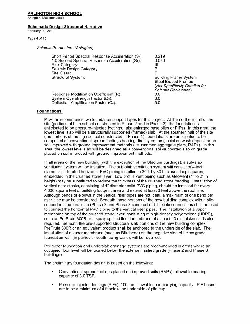
Seismic Parameters (Arlington): Short Period Spectral Response Acceleration (Ss): 0.219 1.0 Second Spectral Response Acceleration (S1): 0.070 Risk Category: III Seismic Design Category: B Site Class: D Structural System: Building Frame System Steel Braced Frames
(Not Specifically Detailed for Seismic Resistance)
Response Modification Coefficient (R): 3.0 System Overstrength Factor (Ω0): 3.0 Deflection Amplification Factor (Cd): 3.0
Foundations:
McPhail recommends two foundation support types for this project. At the northern half of the site (portions of high school constructed in Phase 2 and in Phase 3), the foundation is anticipated to be pressure-injected footings, (aka enlarged base piles or PIFs). In this area, the lowest level slab will be a structurally supported (framed) slab. At the southern half of the site (the portions of the high school constructed in Phase 1), foundations are anticipated to be comprised of conventional spread footings bearing directly on the glacial outwash deposit or on soil improved with ground improvement methods (i.e. rammed aggregate piers, RAPs). In this area, the lowest level slab will be designed as a conventional soil-supported slab on grade placed on soil improved with ground improvement methods. In all areas of the new building (with the exception of the Stadium buildings), a sub-slab ventilation system will be installed. The sub-slab ventilation system will consist of 4-inch diameter perforated horizontal PVC piping installed in 30 ft.by 30 ft. closed loop squares, embedded in the crushed stone layer. Low profile vent piping such as GeoVent (1” to 2” in height) may be substituted to reduce the thickness of the crushed stone bedding. Installation of vertical riser stacks, consisting of 4” diameter solid PVC piping, should be installed for every 4,000 square feet of building footprint area and extend at least 3 feet above the roof line. Although bends or elbows in the vertical riser pipes are not ideal, a maximum of one bend per riser pipe may be considered. Beneath those portions of the new building complex with a pile-supported structural slab (Phase 2 and Phase 3 construction), flexible connections shall be used to connect the horizontal PVC piping to the vertical riser pipes. The installation of a vapor membrane on top of the crushed stone layer, consisting of high-density polyethylene (HDPE), such as PrePrufe 300R or a spray applied liquid membrane of at least 40 mil thickness, is also required. Beneath the pile-supported structural slab portions of the new building complex, PrePrufe 300R or an equivalent product shall be anchored to the underside of the slab. The installation of a vapor membrane (such as Bituthene) on the negative side of below grade foundation wall (in particular south facing walls), will be required. Perimeter foundation and underslab drainage systems are recommended in areas where an occupied floor level will be located below the exterior finished grade (Phase 2 and Phase 3 buildings).
The preliminary foundation design is based on the following:
• Conventional spread footings placed on improved soils (RAPs): allowable bearing capacity of 3.0 TSF.
• Pressure-injected footings (PIFs): 100 ton allowable load-carrying capacity. PIF bases are to be a minimum of 4 ft below the underside of pile cap.

ARLINGTON HIGH SCHOOL Arlington, Massachusetts
Schematic Design Structural Narrative February 20, 2019
Page 5 of 13
Construction Classification:
New construction will be classified as Type IB (Noncombustible, Protected). Floor construction (except concrete floor slabs on steel deck) and roof construction (including the roof deck) will require applied fireproofing to achieve the necessary fire resistance rating. Secondary roof framing members (not connected directly to the columns) that are located at least 20 feet above the floor do not need to be protected (e.g. new Gymnasium). Refer to the Architectural Drawings for additional fire rating requirements at Stairs, Electrical Rooms, etc. There are no firewalls planned in the buildings. All steel framed construction is considered to be restrained.
Sustainable Design Considerations:
Sustainable design considerations will be incorporated into the building design; it is intended that the project will be designed to LEED v4 (silver) standards (minimum). Photovoltaic arrays are proposed at most roofs. Green roofs are also proposed.
III. STRUCTURAL SYSTEMS DESCRIPTION AND QUANTITY ESTIMATES A. SUBSTRUCTURE (Refer to the Schematic Design Structural Drawings)
A10: Foundations As noted above, two types of foundations are anticipated to be constructed. At portions of the high school constructed in Phase 2 and in Phase 3, the foundation is anticipated to be pressure-injected footings (PIFs). The need for a pile load test should be confirmed with McPhail. PIFs are to be installed utilizing cased shafts. In this area, the lowest level slab will be a structurally supported (framed) slab. At portions of the high school constructed in Phase 1, foundations are anticipated to be comprised of conventional spread footings bearing directly on the glacial outwash deposit or on soil improved with ground improvement methods (i.e. rammed aggregate piers, RAPs). In this area, the lowest level slab will be designed as a conventional soil-supported slab on grade placed on soil improved with ground improvement methods. At the PIF-supported areas (all Phase 2 and Phase 3 construction), individual columns (at the building interior and perimeter) will be supported by 100 ton piles with reinforced concrete pile caps. At the building perimeter, reinforced concrete grade beams will span between pile caps, supporting the exterior walls and the edge of the Ground Floor slab. Interior sections of the Ground Floor slab will typically be supported at column locations; single, intermediate slab support piles will be required at larger or atypical structural bays. A thickened, reinforced concrete slab/beam (18” deep) will be provided to brace/tie pile caps, as required (interior single pile and two-pile caps). Pile caps for columns in lateral bracing bays will be tied together with reinforced concrete grade beams. Battered PIFs may be installed along perimeter foundation walls using uncased shafts in order to resist lateral loads, where passive pressure alone is inadequate. There will be a maximum batter of 1 horizontal to 6 vertical (1H : 6V), and the design horizontal load capacity of one PIF is anticipated to be 20 tons. At the conventional shallow foundation area (all Phase 1 construction; including the future expansion area to the east of the STEAM wing), foundations will be spread footings on soil that has been improved with Rammed Aggregate Piers (RAPs). Individual spread footings will be constructed at column locations and continuous wall footings will be constructed at walls. Where the exterior grade matches the floor elevation, a reinforced concrete frost wall will be constructed at the building perimeter. Elsewhere, retaining walls will be required. Reinforced concrete grade beams will interconnect/tie column footings/piers in lateral bracing bays.
Premium foundation costs are anticipated, relating to the 24+/- feet difference in grade from north to south at the site, the phasing complexities, and the adjacency of new foundations to the existing

ARLINGTON HIGH SCHOOL Arlington, Massachusetts
Schematic Design Structural Narrative February 20, 2019
Page 6 of 13
foundations. In particular, a temporary, SOE wall will be required along the entire northern side of the Phase 1 construction (just south of the Fusco and Collomb Buildings) to facilitate Phase 2 and Phase 3 demolition and construction. This system will likely consist of soldier piles and lagging, with lateral ties extending below the Phase 1 foundations (coordinate tie locations with the RAPs installation). Footings at the northwest corner of the Auditorium and at the north end of the STEAM wing west stair, which are close to the Phase 2 SOE wall will be constructed approximately twelve (12) feet below grade, to avoid lateral loads on the SOE wall. Piers will then be constructed, extending to Elevation 75’-0” +/-. Grade beams and a 12” thick structural (framed) slab will be provided in the exterior structural bay in these locations; the construction will be similar to that described for pile-supported Phase 2 and Phase 3 foundation/lower level slab construction.
A two-story retaining wall will be required along the southern edge of the Phase 2 and Phase 3 wings. The walls will be designed for at rest, active soil pressures; lateral earth forces will be resisted by the lateral force resisting system of the building.
Perimeter foundation and underslab drainage systems are recommended in areas where an occupied floor level will be located below the exterior finished grade (Phase 2 and Phase 3 construction). The new bicycle pathway/ramp, the new grandstand sections, the new Stadium Toilet building and the Concessions building will all be supported on oversized spread footings or by helical piles. An SOE wall will be required to construct the Phase 1 pedestrian walkway/ramp along the east side of the site.
A1010 - Standard Foundations Spread Footing Foundation Areas (Phase 1 Wings and Stadium Buildings):
• Typical perimeter frost wall: 14” thick with an 8” wide masonry shelf with horizontal and vertical reinforcing each face (4.5 +/- psf). The outside surface of the perimeter foundation walls will receive a troweled-on bituminous mastic.
• Typical perimeter frost wall at Stadium Toilet Building and Concessions Building: 16” thick with an 8” wide masonry shelf with horizontal and vertical reinforcing each face (4.5 +/- psf). The outside surface of the perimeter foundation walls will receive a troweled-on bituminous mastic.
• Typical perimeter frost wall continuous footing: 2’-6” wide, by 12” deep, with continuous reinforcing bars, plus dowels to the foundation wall (10.0+/- plf). The bottom of the footing will be located 4’-0” minimum below the exterior finish grade for frost protection.
• Typical, average interior column footings (based on 3.0 TSF allowable bearing capacity): 8’-6”x 8’-6” x 24” deep, with 750 lbs. reinforcing. The bottom of the footing will be approximately 3’-6” below the slab on grade.
• Typical, average perimeter column footings (based on 3.0 TSF allowable bearing capacity): 8’-6”x 8’-6” x 24” deep, with 750 lbs. reinforcing. The bottom of the footing will be approximately 5’-0” below the exterior finish grade.
• Typical piers/pilasters at interior/perimeter columns: 24 inches by 24 inches, reinforced concrete with 40 plf reinforcing.
• Typical grade beams interconnecting piers/footings in lateral bracing bays: 2’-0” wide by 2’-6” deep with 50 plf reinforcing. Provide threaded bar terminators at each end of each grade

ARLINGTON HIGH SCHOOL Arlington, Massachusetts
Schematic Design Structural Narrative February 20, 2019
Page 7 of 13
beam. Assume one (1), 30+/- feet long grade beam required for every 1,500 square feet of lowest floor area.
• Foundation Wall Dampproofing: ASTM D1227 Standard Specification for Emulsified Asphalt Used as a Protective Coating for Roofing; Type II, Class I, non-asbestos fibers.
• Anchor Bolts: Anchor bolts at column base plates shall conform to ASTM F1554 - Grade 36 and shall be headed type. There will be a minimum of four (4), ¾” diameter anchor bolts at all columns; additional bolts and/or larger diameter bolts will be required at bracing locations.
Pile Foundation Areas (Phase 2 and Phase 3 Wings):
• Typical, average perimeter grade beams: 24” wide (including an 8” wide masonry shelf) by 42” deep, with top, bottom, and face longitudinal reinforcing bars and closed stirrups (90.0+/- plf), spanning to pile caps. The outside surface of perimeter grade beams will receive a troweled-on bituminous mastic. The bottom of all perimeter grade beams will be a minimum of 4’- 0” below the exterior finish grade for frost protection. The top of grade beam will typically be constructed flush with the top of pile cap.
• Two-story foundation wall along south side of Phase 2 and Phase 3 construction: 18” average thickness with horizontal and vertical reinforcing each face (10.0+/- psf). Provide waterproofing, drainage fabric and a 2’-0” wide column of free draining material on the outside face (soil side) of the wall, which ties into a perimeter foundation drainage system.
• Typical interior piles (based on 100 ton pile capacity): - Gymnasium Wing: 2 piles - 5-story Classroom Wing: 3 piles - 3-story preschool/classroom/office wing: 2 piles - Northern-section of Spine: 4 piles
• Typical perimeter piles (based on 100 ton pile capacity): - Gymnasium Wing: 2 piles - 5-story Classroom Wing: 3 piles - 3-story preschool/classroom/office wing: 2 piles - Black Box Theater: 1 pile - Northern section of Spine: 2 piles
• The top of interior and perimeter pile caps will typically be located 18” below the top of slab.
• Typical intermediate slab support piles: One (1), 100 ton pile per 800± square feet of the Ground Floor slab. Locally thicken the structural slab to 18” deep at each slab support pile.
• Typical pile caps quantities: PC-1: 60 sf formwork, 2.0 cu. yd. concrete, 90 lbs reinforcing PC-2: 90 sf formwork, 5.0 cu. yd. concrete, 280 lbs reinforcing PC-3: 105 sf formwork, 6.0 cu. yd. concrete, 380 lbs reinforcing PC-4: 115 sf formwork, 7.0 cu. yd. concrete, 350 lbs reinforcing
• Typical piers/pilasters at interior/perimeter columns: 24 inches by 24 inches, reinforced concrete with 50 plf reinforcing.
• Typical interior grade beams interconnecting piers/pile caps in lateral bracing bays: 2’-0” wide by 2’-6” deep with 75 plf reinforcing. Provide threaded bar terminators at each end of each grade beam. Assume one (1), 30+/- feet long grade beam required for every 1,500 square feet of lowest floor area.

ARLINGTON HIGH SCHOOL Arlington, Massachusetts
Schematic Design Structural Narrative February 20, 2019
Page 8 of 13
• Anchor Bolts: Anchor bolts at column base plates shall conform to ASTM F1554 - Grade 36 and shall be headed type. There will be a minimum of four (4), ¾” diameter anchor bolts at all columns; additional bolts and/or larger diameter bolts will be required at bracing locations.
Phase 4 Site Photovoltaic (PV) Panel Foundations: PV panel arrays will be installed at various locations on site; including the surface parking lot and
in the area of the existing, northern section of bleachers. Steel framed supports for the PV arrays will be provided by others; however, foundation work for the supports is included in the scope of the High School project.
• Typical PV frame footing for parking lot arrays: 6’-0”x 6’-0” x 20” deep, with 275 lbs. reinforcing. The bottom of the footing will be 4’-0” (minimum) below the finished grade. Note that drilled shafts/caissons may be required to resist the overturning moments associated with these structures.
• Typical PV frame footing at north bleacher array: Re-use existing bleacher footings to the extent practical; otherwise provide a 4’-6”x 4’-6” x 16” deep, with 125 lbs. reinforcing. The bottom of the footing will be 4’-0” (minimum) below the finished grade (provide typical reinforced concrete pier).
A1020 - Special Foundations
• Elevator pits: Phase 2 Elevator pit construction will consist of 12” thick, reinforced concrete walls and a 2’-6” thick, reinforced concrete foundation mat with an integral sump pit, supported on four (4) piles. Phase 1 elevator pit construction will be similar, with a 2’-0” thick, reinforced concrete, soil-supported foundation mat. Waterstops will be provided at all construction joints and all interior surfaces of the elevator pit will be waterproofed. Elevator pit walls will support 8” thick, 100% solid grouted, reinforced concrete masonry unit (CMU) construction elevator shaft walls.
A1030 - Lowest Level Slabs
Spread Footing Foundation Areas (Phase 1 Wings and Stadium Buildings): The lowest level of floor construction (Second Floor in Phase 1 Wings) will typically be a 6” thick, concrete slab on grade, reinforced with #4 bars @15” o.c. in each direction. As described earlier in this Narrative, the slab will be underlain by a vapor mitigation system (except at the Stadium Toilet building and the Concessions building). Full depth isolation joints will be constructed around columns. Depressions will be required at entrance mats and at Toilet Rooms. Floor finishing will be coordinated with flooring requirements. Piping for radiant heat will be embedded into the slab, or in a separate topping slab. Pile Foundation Areas (Phase 2 and Phase 3 Wings): The lowest level of floor construction (Ground Floor) will typically be an average, 12” thick, concrete structural slab on grade with 8.5 psf of reinforcing, supported by interior pile caps at columns (and at mid-bay at some locations) and by reinforced concrete grade beams at the building perimeter. The slab will be underlain by a vapor mitigation system as described earlier in this Narrative. Depressions (approximately 8” deep) will be required at coolers in the Kitchen. Elsewhere, depressions will be required at entrance mats, Toilet Rooms, and at the Gymnasium wood floor. Floor finishing will be coordinated with flooring requirements. Piping for radiant heat will be embedded into the slab, or in a separate topping slab.

ARLINGTON HIGH SCHOOL Arlington, Massachusetts
Schematic Design Structural Narrative February 20, 2019
Page 9 of 13
B. SHELL (Refer to the Schematic Design Structural Drawings) B10: Superstructure
Structural Bays/Spans: Refer to the Schematic Design Structural Drawings. Story Heights/Floor Elevations: Refer to the Schematic Design Structural and Architectural Drawings.
Steel Framing Connections: Type 2 simple framing connections (shear only); double clip angles typically.
Columns: Typical columns will be wide flange steel sections or steel tubes (HSS). Refer to the Schematic Design Structural Drawings. Lateral Force Resisting System: Lateral (wind and seismic) forces will be resisted by steel bracing, for reasons of economy, stiffness, reduced structural depth and smaller column sizes. Bracing members will be square or rectangular HSS sections. Brace configurations may include chevrons, inverted chevrons (“V”), or single diagonals in short bays, as required by structural and architectural considerations. Rigid steel moment frames will be provided in locations where bracing is not feasible. Lateral forces at the Stadium Toilet building and the Concessions building will be resisted by reinforced masonry (CMU) walls. Refer to the Schematic Design Structural Drawings. Expansion (Seismic) Joints: Four (4) expansion joint locations are proposed, dividing the new high school into five (5), structurally separate sections. One joint will be located on the east and south sides of the Gymnasium Wing, isolating the Gymnasium building from the central Spine and the Black Box Theater. A second joint will be located at the east side of the five-story classroom wing, separating this building from the three-story preschool/classroom/office wing. A third joint will be located south of the Black Box Theater, extending east through the Spine, wrapping around the STEAM wing west stair shaft, and continuing south to the north face of the building. The fourth joint separates the Auditorium and southern portion of the spine from the four-story STEAM wing. Refer to the Schematic Design Structural Drawings.
Fire protection: As previously noted, new construction will be classified as Type IB (Noncombustible, Protected). Floor construction (except concrete slabs on steel deck) and roof construction (including the roof deck) will require applied fireproofing to achieve the necessary fire resistance rating. Secondary roof framing members (not connected to columns) that are located at least 20 feet above the floor do not need to be protected (e.g. new Gymnasium). Refer to the Architectural Drawings for additional fire rating requirements at Stairs, Electrical Rooms, etc. There are no firewalls planned in the buildings. All steel framed construction is considered to be restrained.
Elevator Shafts: New elevator shafts will be 8” thick, 100% solid grouted, reinforced CMU construction, supported on 12” thick reinforced concrete elevator pit walls and a reinforced concrete elevator pit mat.

ARLINGTON HIGH SCHOOL Arlington, Massachusetts
Schematic Design Structural Narrative February 20, 2019
Page 10 of 13
B1010 - Floor Construction
Typical Upper Level Floor Construction: 4½” thick (minimum), normal weight concrete topping slab on a 2” deep, 18 gauge, composite type, galvanized steel floor deck (6½” minimum total slab thickness), reinforced with welded wire fabric, spanning to composite wide flange steel beams. Steel beams span to composite wide flange steel girders that are supported by wide flange steel columns or HSS (tube) steel columns. All composite steel beams and girders will be unshored. Composite action will be achieved by field welding ¾” diameter x 5” long headed shear studs through the deck, to the top flanges of the beams and girders. To avoid compromising composite action, conduit or other, similar embedded items (e.g. radiant heating tubes) should not be placed in the concrete slab on steel deck construction. Slabs on composite steel floor deck will be placed at the required elevation, adding concrete to compensate for the deflection of the (unshored) steel framing (assume an approximate average of ¾” additional concrete required over the bay area).
Steel framed platforms (with steel grating and railings), supporting MEP/FP equipment, will be suspended
from the Second Floor level of the Phase 2 and Phase 3 wings. Refer to the Schematic Design Architectural
and MEP/FP Drawings for locations and extent.
The estimated total weight of structural steel for the various, steel framed areas of new floor and roof construction (including beams, columns, joists, bracing, plates, angles, relieving angles, miscellaneous frames, supports, connections, etc., but excluding loose lintels, entry canopies, catwalks and mechanical platforms, site structures, galvanized equipment screens (refer to Schematic Design Architectural Drawings), etc., is as follows:
Estimated Weight of Structural Steel: 3,530 Tons
Estimated Weight of Open Web Steel Joists and Accessories: 160 Tons
Galvanized Equipment Screens: 125 pounds of steel per linear foot
B1020 - Roof Construction
Typical Roof Construction:
Typical Roof Construction (except Gymnasium roofs): 1½” deep, 18 gauge, galvanized steel roof deck spanning to wide flange steel beams. Steel beams are typically supported by wide flange steel girders, which span to wide flange steel columns or HSS (tube) steel columns. As noise and vibration will be a concern where rooftop mechanical equipment is located, roof areas with rooftop equipment will be 1½” deep, 18 gauge, composite type galvanized steel floor deck with a 3½” (minimum) deep, normal weight concrete topping slab (5” minimum total thickness), supported by composite, wide flange steel beams and girders. The composite steel floor deck will require applied fireproofing at these locations. Galvanized steel frames, constructed with HSS members and field bolted connections, will support acoustic/visual screens around rooftop equipment where desired. The screen will be designed and detailed to accommodate the installation of PV panels/supports (by others).
Gymnasium Roof Construction: 3” deep, 18/20 gauge, galvanized steel cellular roof deck supported by clear-spanning, deep long span bar joists and wide flange steel girders. An acoustic treatment will be applied to the Gymnasium roof deck.
Green Roof Construction (Spine Low Roof and potentially over the Black Box Theater): 4½” thick (minimum), normal weight concrete topping slab on a 2” deep, 18 gauge, composite type, galvanized steel floor deck (6½” minimum total slab thickness), reinforced with welded wire fabric, spanning to composite wide flange steel beams.

ARLINGTON HIGH SCHOOL Arlington, Massachusetts
Schematic Design Structural Narrative February 20, 2019
Page 11 of 13
Where practical, roof drainage will be achieved by sloping the steel to the internal drains. Some areas of tapered insulation should be anticipated, at locations where it is not practical to slope the steel. Plaza/roof construction over the Phase 2 loading dock/service area will be a 14” thick, reinforced concrete structural slab with 10.5 psf reinforcing. Roof construction at the Stadium Toilet building and the Concessions building will be ¾” tongue and groove, exterior grade Structural 1 plywood sheathing, supported by 18” deep, engineered wood I-joists. Wood joists are supported by reinforced masonry (CMU) bearing walls.
Estimated Weight of Structural Steel: Included in B1010 Above B20: Exterior Enclosure
B2010 - Exterior Walls Exterior walls will typically be masonry veneer (cavity wall construction), with areas of glazed curtainwall and architectural panels. A galvanized, light gauge steel stud backup wall (16 gauge minimum thickness) will be constructed at masonry veneer areas. Vertical slip joints will be provided in the metal stud backup system at each level. Continuous galvanized steel relieving angles will be provided at each floor level to limit the height of masonry veneer to 30+/- feet. Intermediate, HSS steel girts will be provided at the Auditorium and Gymnasium exterior walls, at multi-story curtain walls, and between the Ground and Second Floors at the north exterior walls of the Phase 2 classroom wing, to laterally support the wall construction at mid-height.
IV. STRUCTURAL OUTLINE SPECIFICATIONS:
Concrete:
• All concrete shall be normal weight, 4,000 psi at 28 days, except foundation walls and footings, which shall be normal weight, 3,000 psi and exterior (exposed) concrete (paving) which shall be normal weight, 4,500 psi.
• Portland Cement: ASTM C150, Type I or II.
• Fly Ash: ASTM C618, Class F. Replacement of cement content with fly ash is limited to 20% (by weight). Fly ash is not permitted in exterior, exposed concrete, slabs on grade or slabs on steel deck.
• All concrete shall be proportioned with ¾” maximum aggregate, ASTM C 33, except 3/8” maximum aggregate shall be used at toppings less than 2” thick (e.g. metal pan stairs).
• All reinforcing shall be ASTM A615 deformed bars, Grade 60.
• All welded wire fabric shall conform to ASTM A185.
• Underslab Vapor Membrane: 40 mil minimum HDPE vapor barrier (e.g. Preprufe 300R by
Grace or equal).
• Reinforcing bars, steel wire, welded wire fabric, and miscellaneous steel accessories shall contain post-industrial/post-consumer recycled content (the percentage of recycled content is based on the weight of the component materials). Certification of recycled content shall be in accordance with Submittal Requirements.

ARLINGTON HIGH SCHOOL Arlington, Massachusetts
Schematic Design Structural Narrative February 20, 2019
Page 12 of 13
• Concrete products manufactured within 100 miles (by air) of the project site shall be documented in accordance with Submittal Requirements.
• Cure all concrete by moisture retention methods, approved by Architect; curing compounds shall not be used.
Reinforced Concrete Masonry (Elevator Shafts and Stadium Buildings):
• Masonry construction shall conform to ACI 530-13/ASCE 5/TMS 402 “Building Code Requirements for Masonry Structures”.
• Masonry strength, f’m shall not be less than 1500 psi.
• Requirements for load bearing block strength shall be as required for specified masonry strength (f’m) but shall not be less than 2000 psi on the net area of the block.
• Grout shall conform to ASTM C476, Type Fine, and shall be of strength required for specified masonry strength (f’m) but not less than 3000 psi.
• Mortar for reinforced masonry shall conform to ASTM C270 Type S and shall be of strength required for specified masonry strength (f’m) but not less than 1800 psi.
• Reinforcing bars shall conform to ASTM A615, Grade 60 deformed bars. Lap all continuous bars 48 diameters and provide bar positioners. Assume No. 5 bars at 2’-8” o.c. vertically and horizontal bond beams with 2 – No. 5 continuous at 4’-0” o.c.
• Joint reinforcing shall be 9-gauge Ladder Type conforming to ASTM A82. Provide prefabricated corners and tees. Walls shall be reinforced horizontally with joint reinforcing at 16 inches on centers unless otherwise noted.
• Reinforcing bars, steel wire, and miscellaneous accessories shall contain (combined) post-industrial/post-consumer recycled content (the percentage of recycled content is based on the weight of the component materials). Certification of recycled content shall be in accordance with Submittal Requirements.
• Elevator and stair shaft walls shall be 100% solid grouted (all cores); low lift grouting.
• Masonry products extracted/harvested and manufactured within 100 miles (by air) of the project site shall be documented in accordance with Submittal Requirements.
Structural Steel:
• Structural steel shapes shall conform to ASTM A992, Fy = 50 ksi.
• Square and rectangular steel tubes (HSS) shall conform to ASTM A500, Grade C, Fy = 50 ksi.
• Round steel tubes (HSS) shall conform to ASTM A500, Grade B, Fy = 46 ksi.
• Structural steel plates and bars shall conform to ASTM A36, Fy = 36 ksi.
• Steel members shall contain (combined) post-industrial/post-consumer recycled content (the percentage of recycled content is based on the weight of the component materials). Certification of recycled content shall be in accordance with the Submittal Requirements.

ARLINGTON HIGH SCHOOL Arlington, Massachusetts
Schematic Design Structural Narrative February 20, 2019
Page 13 of 13
• Steel extracted/harvested and manufactured within 100 miles (by air) of the project site shall be documented in accordance with the Submittal Requirements.
• Anchor Bolts: Anchor bolts at column base plates shall conform to ASTM F1554 – Grade 36 and shall be headed type. Provide a minimum of four (4), ¾” diameter anchor bolts at all columns; additional bolts and/or larger diameter will be required at bracing locations.
• Bolted connections shall be ASTM A325, Type N (bearing) bolts, except slip-critical bolts shall be used at lateral brace beam connections.
• Shear connectors shall be ¾” diameter, 5” long, headed Nelson studs conforming to ASTM A108. Assume that 25 shear connectors are required for every 100 square feet of floor area.
• Shop and field welding shall be AWS D1.1 E70XX electrodes.
• Surface treatment for typical structural steel: SSPC Surface Preparation No. 3 (Power Tool Cleaning). Structural steel shall be left unprimed.
• Surface treatment for exposed Structural Steel shall be SSPC Surface Preparation No. 6
(Commercial Blast Cleaning). Structural steel shall receive one coat of shop primer that is compatible with the finish paint.
• All exterior, exposed structural steel shall be hot-dipped galvanized.
Steel Deck:
• Typical steel roof deck shall be 1½” deep, 18 gauge, Type B, conforming to ASTM A653, Grade 33 (minimum), galvanized in accordance with ASTM A 653, coating class G60.
• Gymnasium roof deck shall be 3” deep, 18/20 gauge cellular type, conforming to ASTM A653, Grade 33 (minimum), galvanized in accordance with ASTM A653, coating class G60. Gymnasium roof deck shall be shop treated and painted with a primer that is compatible with the finish paint.
• Composite steel floor deck shall be 2” deep, 18 Gauge, composite type, conforming to ASTM A653, Grade 40, galvanized in accordance with ASTM A 653, coating class G60.
• All steel floor deck and roof deck accessories (pour stops, finish strips, closures, etc.) shall be the same finish as the deck; 18 gauge minimum.
• Steel deck shall contain a minimum of 25% (combined) post-industrial/post-consumer recycled content (the percentage of recycled content is based on the weight of the component materials). Certification of recycled content shall be in accordance with the Submittal Requirements.
• Steel deck extracted/harvested and manufactured within 100 miles (by air) of the project site shall be documented in accordance with the Submittal Requirements.
• Provide 14 gauge sump pans at roof drains.
End of Schematic Design Structural Narrative


Arlington High School – Foodservice Narrative
ARLINGTON HIGH SCHOOL
ARLINGTON, MA
Foodservice Narrative Report for New Construction

Arlington High School – Foodservice Narrative
INTRODUCTION
As requested by HMFH Architects, Colburn Guyette a Foodservice Design Consulting firm is
providing this narrative as a high-level overview of the foodservice design and operation for the
proposed new High School facility.
OVERVIEW
The Arlington High School population currently is 1,300 students based on information provided
by school staff. The future projected enrollment is estimated at 1,755 students as outlined in the
project RFP. Based on MSBA space guidelines, we estimate approximately 3,055 square feet will
be allocated to the kitchen and serving space with an additional 600 square feet for a scramble
type serving design, for a total of 3,655 square feet. Based on the 3,655 square feet, we
estimated the budget for food service equipment to be $730,000 delivered and installed. This is
based on our square foot estimate of $200 PSF. This does not include hard construction or work
required by trades.
There are three lunch periods currently with no plans to revise that in future. There are four
cashiers utilized during meal periods and this will continue with any new operation. Current
foodservice staff consists of eleven employees. It is yet to be determined if more staff will be
necessary in the new facility. Assuming participation will increase in the new facility, this may be
required.
FOOD SERVICE OPERATIONS
Typical kitchen functions to be provided:
Walk-In Cooler/Freezer Storage
Dry Storage Room
Food prep/work tables
Food Preparation Equipment
Cooking Equipment
Exhaust Hood(s) with associated Fire Suppression System(s)

Arlington High School – Foodservice Narrative
Mop Closet
Lockers
3 Bay Pot Sink
Dishroom (for pots and pans)
Typical serving functions to be provided:
Hot & Cold Service Counters
Sneeze Guards
Refrigerated Milk Coolers
Salad Bar
Hot Holding Cabinets
Refrigerated Holding Cabinets
Grab and Go Area
Cashier Station
POS System
PROPOSED KITCHEN DESIGN
This project will take into consideration the design of a zero net energy building to
operate without the use of fossil fuels. This will include the LEED rating system. Due to
the proposed net zero initiative, all equipment specified for the foodservice operation
will be electric.
The kitchen will be designed with sustainability and efficiency as the main goals for the
operation. It will take into consideration the most efficient flow from delivery of food
product to food waste management, all while providing the most sustainable methods
and reducing energy consumption.
Examples of the proposed equipment in the kitchen to reach the goals will be as follows:
Energy Star rated equipment
Sustainable refrigerants (CFC-Free)
Reverse cycle defrosts for walk-in freezer

Arlington High School – Foodservice Narrative
High efficiency lighting for walk-in storage and exhaust hoods
Heat reclamation
Demand ventilation controls
Water extraction for food waste
Cloud based monitoring of equipment for maximum efficiency
Water saving features wherever possible
Waste water reduction
Proper chemical storage
Low water ventless dishmachine for reusable wares replacing single use materials
Sustainable collection and storage methods for compost and recycling
PROPOSED SERVERY DESIGN
The servery for the high school will provide a pleasant dining experience for students
that promotes healthy food delivery, contributing to healthy habits in an environment
that is suited for today’s high school students. The flow from entrance, meal delivery to
exit will be designed for maximum efficiency for the staff, while providing a non-
congested free flowing serving area where students can make choices, have variety and
still maintain nutritional standards set forth by the state mandates for school
foodservice.
Examples of the proposed equipment in the servery to reach the goals will be as follows:
Energy Star rated equipment
Sustainable refrigerants (CFC-Free)
Formaldehyde free millwork
Low VOC sealants
Use of recycled content materials if possible
In general, the foodservice spaces will utilize energy efficient lighting, occupancy sensors,
reduced water flow valves, low VOC materials, reduced make-up air volumes through highly
efficient exhaust systems, remote temperature monitoring, sustainable grease management
and recirculating water usage when possible.

Arlington High School – Foodservice Narrative
The following is an estimated all-inclusive list of foodservice equipment for the project:
Qty Description
1 Freezer Condensing Unit
2 Cooler Coil
1 Cooler Condensing Unit
1 Hand Sink
1 Soap Dispenser
1 Paper Towel Dispenser
1 Disposer/Controls
1 Soiled Dishtable & Pot sink
1 Pre-Rinse Assembly
1 Pre-Rinse Assembly
1 Disposer/Controls
1 Eye Wash Station
1 Dishmachine
1 Clean Dishtable
1 Wall Shelf w/ Pot Hooks
1 Janitor Shelving
1 Mop Sink
1 Ice Cuber w/ Bin
1 Electric Vegetable Spinner
1 Scale
1 mobile stand
4 Mobile Pot Shelf
1 Exhaust Hood
1 Exhaust Hood
1 Double Acting Mixer
1 40 Gal. Tilt Skillet
1 40 Gal. Tilt Skillet
1 Mobile Work Table
1 Floor Trough
1 60 Gallon Tilting Kettle
1 Prep Table W/ Sinks
1 Combi-Oven
1 Hand Sink
1 Touchless Soap Dispenser
1 Utility Distribution System
1 Exhaust Hood
1 Exhaust Hood
1 Combi-Oven

Arlington High School – Foodservice Narrative
1 Overshelf
1 Mobile Work Table
1 Combi-Oven
1 Overshelf
1 Mobile Work Table
1 Scale
1 mobile stand
1 Overshelf
1 Mobile Work Table
1 Overshelf
1 Mobile Work Table
1 Slicer
1 Hand Sink
1 Touchless Soap Dispenser
1 Touchless Paper Towel Dispenser
1 Mobile Work Table
1 Mobile Work Table
1 60 Qt. Mixer
1 Prep Table w/ Sinks
1 Disposer/Controls
1 Overshelf
1 slicer
1 Hand Sink
1 Touchless Soap Dispenser
1 Touchless Paper Towel Dispenser
1 Staging/Production Cooler
1 Walk-In Blast Chiller
1 Blast Chiller Condensing Unit
1 Cooler Coil
1 Cooler Condensing Unit
1 Cooler Coil
1 Cooler Condensing Unit
1 Trash Bin
1 Prep Table w/ Sinks
1 Disposer/Controls
1 Buffalo Chooper
1 Overshelf
1 Work Table
1 Food Processor
1 Slicer
12 Roll-In Pan Rack

Arlington High School – Foodservice Narrative
17 Dry Storage Shelving
4 Dry Storage Shelving
6 Dry Storage Shelving
1 Dry Storage Shelving
2 Dry Storage Shelving
1 Manual Clipper
1 Hand Sink
1 Touchless Soap Dispenser
1 Touchless Paper Towel Dispenser
1 Disposer/Controls
13 Trash Bin
1 Pass-Thru Refrigerator
1 Pass-Thru Heated Cabinet
1 Back Work Counter w/ Hand Sink
1 Touchless Soap Dispenser
1 Touchless Paper Towel Dispenser
1 Main Serving Counter
1 Hot/Cold Food Wells
1 Sneeze Guard w/ Heat & Light
1 Hot/Cold Food Wells
1 Sneeze Guard w/ Heat & Light
1 Back Work Counter w/ Hand Sink
1 Pass-Thru Refrigerator
1 Pass-Thru Heated Cabinet
1 Back Work Counter w/ Hand Sink & Dump
Sink
1 Touchless Soap Dispenser
1 Touchless Paper Towel Dispenser
1 Hot/Cold Food Wells
1 Sneeze Guard w/ Heat & Light
1 Pass-Thru Refrigerator
1 Pass-Thru Heated Cabinet
1 Back Work Counter w/ Hand Sink
1 Touchless Soap Dispenser
1 Touchless Paper Towel Dispenser
2 Flammable Safety Cabinet
1 Hot/Cold Food Wells
1 Sneeze Guard w/ Heat & Light
4 Dunnage Rack
1 Dunnage Rack
1 Cooler Coil
1 Cooler Condensing Unit

Arlington High School – Foodservice Narrative
1 Air Screen Merchandiser
1 Air Screen Merchandiser
1 Air Screen Merchandiser
1 Air Screen Merchandiser
1 P.O.S. System
1 Cashier Counter
1 P.O.S. System
1 P.O.S. System
1 Mobile Condiment Counter
1 Mobile Condiment Counter
1 P.O.S. System
1 Cashier Counter
1 Cashier Counter
1 Cashier Counter
1 Mobile Trash/Recycle/Compost Drop
1 Mobile Trash/Recycle/Compost Drop
1 Mobile Trash/Recycle/Compost Drop
1 Mobile Trash/Recycle/Compost Drop
END OF REPORT

FIRE PROTECTION
210000 - 1
ARLINGTON HIGH SCHOOL
FIRE PROTECTION BUILDING SYSTEMS
SCHEMATIC DESIGN NARRATIVE
A. General:
1. Furnish all materials, equipment, transportation and labor for the complete and operating installation of the Fire Protection Systems.
2. All occupiable and accessible areas of the building will be protected with a complete combination standpipe and wet suppression sprinkler system.
3. Work shall be performed using the "Method "B" Shared Design" process, from a "Fully Engineered" "design" set of documents which outlines the system and requires the Fire Protection Contractor to provide the "installation" set of documents, in conformance with the design criteria as set forth in the bid documents. Work shall be performed in accordance with the Building Code, NFPA, and the Local Authority.
B. Specific System Requirements and Criteria are as follows:
1. Complete combination standpipe and hydraulically calculated, automatic overhead, wet suppression sprinkler systems, providing proper coverage to all areas of the new high school building.
2. Eight inch dedicated/primary sprinkler water service which shall be extended from the site water main to all devices, equipment and heads. An 8 inch back-up water supply is to also be planned from the opposite end of the building. (PIV, if required.) (Note: All dedicated site water piping, fire hydrants, etc., are required by law to be installed by a licensed Sprinkler Contractor.)
3. Double check type backflow preventer with supervised valves, repair kit, certified test and DEP permit for each of the two building services.
4. Building fire department connections. Two shall be planned at this time based on the overall high school size and site configuration.
5. Based on water flow tests conducted in December of 2018 and preliminary hydraulic calculations, it has been determined that a fire pump will be required to supply this high-rise high school building. Preliminary fire pump sizing 1000 gpm at 70 psi boost, 75 HP motor.
6. Alarm check valves, valves and all piping, hangers, sprinkler heads and accessories. Refer to drawings for quantity of alarm check valves and anticipated sprinkler zone requirements for the high school building.
7. Based on the overall building area, each major building segment with an area not to exceed 52,000 SF per floor, is to be fed via a separate alarm check valve/system riser. Each of these risers are to supply a combination fire sandpipe and sprinkler system.
8. The fire standpipe system within a building segment will generally consist of a standpipe riser to be located in each required exit stairway and where otherwise required by code such as at the stage. Each standpipe riser is to supply a hose valve per floor.

Arlington High School Schematic Design Narrative February 20, 2019
FIRE PROTECTION
210000 - 2
9. The sprinkler system within each building segment will start from one of the required fire standpipe risers with a control valve assembly for each floor.
10. Fire standpipe and sprinkler system zoning is to be consistent with the project phasing.
11. Project consists of phased construction and phased demolition. Refer to Phasing documents for phasing and enabling requirements. Scope of Work is to include at a minimum the following:
a. Capping of all services at the existing building exterior walls to allow demolition/removal of all interior fire protection systems as each existing building segment gets to be demolished.
b. Capping of all services that extend to supply the existing high school.
c. All temporary and permanent service shutdowns to be completed shall be coordinated with the phasing of the project and with the corresponding utility company.
d. Provide for all temporary service relocations to maintain existing building operational prior to final demolition.
e. The STEAM wing will be designed as to allow expansion in the future of Floors 2, 3, 4, and 5.
12. Hydrant flow tests, by this Contractor, to verify the design basis, system sizing, hydraulic calculations, etc.
13. Sprinkler system drains.
14. OS&Y, gate, check and drain valves.
15. Flow switches, inspector's test assemblies and miscellaneous items.
16. Preparation and submittal of complete Fire Protection Working Drawings and hydraulic calculations, to the Engineer, through the Architect, for review.
17. Shop and Record Drawings.
18. Owner and Maintenance Manuals.
19. Testing of all piping systems, devices and alarms.
20. Sleeves, escutcheons, hangers and supports, including seismic support requirements.
21. Pipe and equipment identification.
22. Scaffolding, hoisting and rigging for the fire protection work.
23. Coordination drawings.
24. Sprinkler heads.
25. Design Criteria
a. All systems shall be hydraulically calculated and demonstrated to provide for the minimum required water densities over the hydraulically most demanding

Arlington High School Schematic Design Narrative February 20, 2019
FIRE PROTECTION
210000 - 3
rectangular area. The Contractor shall verify all design criteria affecting the systems with the Engineer of Record, the Insurance Underwriter and local Authorities prior to hydraulic calculations, system sizing and fabrication of materials. Include hose allowances as required, and add a 10 psi cushion for non-ideal distribution of water in the system and other limitations.
1) Hose allowance as required.
2) Light hazard areas at .10 (**) GPM over the hydraulically most remote 1500 (**) SF for all classroom and general areas.
3) Group I Ordinary Hazard areas at .15 (**) GPM over the hydraulically most remote 1500 (**) SF for areas including mechanical, Kitchen, and similar areas.
4) Group II Ordinary Hazard areas at .20(**) GPM over the hydraulically most remote 1,500 (**) SF for areas such as storage rooms.
(** = Densities and areas need to be reviewed with the Engineer of Record, the Insurance Carrier and Authorities.)
b. The standpipe system shall be designed and hydraulically calculated per the Massachusetts State Building Code, CMR-780, Ninth Edition, to satisfy minimum pressure requirements for the flowing standpipe hose valves. In addition, perform hydraulic calculations of the standpipe system to verify that NFPA-14, Standpipe Systems criteria of 100 psi pressure requirements can be achieved at the outlet of the required hose valves with the Fire Department Inlets utilizing the Local Authority's pumper equipment.
H:\60-17-442\ADMIN - Arlington High School\ADDENDUMS-BULLETINS-NARRATIVES\17-442-006-Fire Protection SD Narrative.docx

PLUMBING 220000 - 1
ARLINGTON HIGH SCHOOL
PLUMBING BUILDING SYSTEMS
SCHEMATIC DESIGN NARRATIVE
A. General:
1. Furnish all materials, equipment, transportation and labor for the complete and operating installation of the Plumbing systems.
2. All work shall be performed in strict accordance with the State Building Code, the State Plumbing and Fuel Gas Codes, the plumbing inspector and all Local Codes and Ordinances.
3. This project is proceeding with the possibility of obtaining a LEED certification. Pricing should identify the inclusion of the following items:
a. Battery operated sensor type ultra-low flow urinals (1/8 gallons per flush [GPF]).
b. Battery operated sensor type water closets (1.1 GPF).
c. Battery operated sensor type low flow faucets (0.35 gallons per minute [GPM]).
d. Low flow shower heads (1.5 GPM).
B. Specific System Requirements and Criteria are as Follows:
1. Six inch primary domestic water service to 10 feet-0 inch outside building wall for the new high school building. Four inch back up domestic water service to come in at the opposite end of the building. Three inch water service for the concession building.
2. For the new high school, natural gas service and meter for new Science Rooms with work beginning at the house side of the Gas Company's (new) outside meter that is to include remote monitoring via the building automation system. Service and meter will be by the Gas Company. However, handling of the Gas Company and the Owner's application for gas service shall be by this Contractor. (At this time, it is appropriate to identify a gas company backcharge for this work.) Each of the major gas system components such as Science Room gas outlets shall each be supplied with a dedicated gas system to be fed via a gas sub-meter that shall also be monitored via the building automation system.
3. Internal storm water roof drainage systems from all flat roof areas, consisting of roof drains and all rainwater piping and accessories to points 10 feet outside of the building walls. It is to be assumed at this time that most building roof areas will not need to be provided with a secondary roof drainage system. At this time, it is to be assumed that only a few isolated building roof segments will require a secondary roof drainage system. This requirement will need to be reviewed and confirmed from a structural standpoint. The secondary system will need to be independently piped to daylight.
4. Complete sanitary, waste and vent system connecting to all fixtures and inlet connections, and running to points 10 feet outside of the building walls.

Arlington High School Schematic Design Narrative February 20, 2019
PLUMBING 220000 - 2
5. Dedicated tempered water system including master mixing valve and dedicated tempered water circulation system to supply all emergency shower and eyewash units with a non-stagnant system.
6. Dedicated special waste piping system serving Science Rooms and related areas susceptible to receive non-conventional waste and this system is to consist of:
a. Central pH adjustment and monitoring system.
7. Reduced pressure backflow preventers on hot and cold water supply to the Science Classrooms. This dedicated system is to also include a circulation system with an integral hot water maintenance system.
8. Dedicated "grease waste" piping system from the Kitchen area and from the Culinary area to 10 feet outside building wall, for continuation by Site/Civil to site grease tank/interceptor. Refer to the Kitchen and Culinary areas for the extent of the plumbing work required to support the intended equipment. Provide allowance for two interior grease interceptors to support these two spaces. Provide allowance also for floor drains to support the intended equipment.
9. Domestic hot water shall be set up to be generated by multiple hot water systems for the high school. Each set up shall have a mixing valve, all accessories and devices and a building pumped recirculation loop. A booster will be required in the kitchen, 140 to 180 degrees F as required. Each Major building area will be supplied by a separate hot water system:
a. The main kitchen and showers will be supplied by a system to consist of two storage type heaters. Each heater is to include internal coils to allow preheating of the cold water supply with hot water supplied from the geothermal system by the HVAC Contractor. The preheated water is to be heated further to the required system temperature by utilizing electric coils. Each storage heater is to be as manufactured by PVI Series dual fuel EZ plate storage type and Durawatt electric packaged heater.
b. The Science segment of the high school is to be supplied by a single storage type heater. This heater is to be similar in style to the kitchen and shower's water heating system.
c. Each of the other sets of stacked toilet rooms required in the building will be supplied by a storage type electric water heater to be as manufactured by AO Smith Series DSE.
d. Plumbing fixtures that are located too far away from the hot water systems described under items a, b, and c will need to be supplied by separate point-of-use water heaters wherever feasible.
10. The toilet facility building is intended to be supplied with a high efficiency electric type storage unit.
11. Complete interior sanitary, waste, vent, gas, cold water, 120°F hot water, 140°F hot water and two recirculation piping systems.
12. Main water meter with monitoring via building automation system. A sub-meter for each major system including the following: Kitchen, domestic hot water system.

Arlington High School Schematic Design Narrative February 20, 2019
PLUMBING 220000 - 3
13. Plumbing fixtures and trim, all new, commercial grade and high efficiency types for an anticipated approximately 40 percent water saving: 1.1 GPF water closets, 1/8 GPF urinals, 0.35 GPM lavatories, 1.5 GPM showers, 1.5 GPM Kitchen faucets, etc.
14. Freezeproof wall hydrants around the perimeter of all construction.
15. Drains, hose bibbs, valves, fittings, hangers and all miscellaneous pipeline accessories, including seismic support requirements.
16. Cleaning and testing of all fixtures, equipment and piping systems.
17. Disinfection of all domestic water piping systems.
18. Waste outlets to accept HVAC condensate and sprinkler waste discharges.
19. Shop drawings, record drawings, guarantee, O&M Manuals and Instructions to the Owner.
20. Pipe and equipment identification, valve tags and charts.
21. Insulation of all domestic water piping, roof drain bodies, storm water piping, water cooler drain piping and all exposed piping at handicapped fixtures.
22. Scaffolding, hoisting and rigging for all plumbing work.
23. Toilet room accessories (installation only).
24. All floor drains shall be provided with automatic trap primers.
25. Include allowance for floor drainage and hose bibbs in all mechanical type spaces and large toilet rooms (with two or more fixtures).
26. Project consists of phased construction and phased demolition. Refer to Phasing documents for phasing and enabling requirements. Scope of Work is to include at a minimum the following:
a. Capping of all services at the existing building exterior walls to allow demolition/removal of all interior plumbing systems as each existing building segment gets to be demolished.
b. Capping of all services that extend to supply the existing high school.
c. All temporary and permanent service shutdowns to be completed shall be coordinated with the phasing of the project and with the corresponding utility company.
d. Provide for all temporary service relocations to maintain existing building operational prior to final demolition.
e. The STEAM wing will be designed as to allow future expansion of Floors 2, 3, 4, and 5.
27. It is to be assumed that the Wood Shop will be required to be provided, at a minimum, with a compressed air system to serve all required equipment and outlets, a service sink, and all other required plumbing connections. Refer to equipment drawing and/or architectural for similar spaces that may require plumbing connections to be accounted at this time as part of the project scope.

Arlington High School Schematic Design Narrative February 20, 2019
PLUMBING 220000 - 4
28. It is to be assumed that according to current state elevator code, elevator pits will be required to include a drainage system. The system is to consist of a pit floor drain to discharge into a sump pump system with discharge pipe to be extended to the building sanitary system.
29. Swing Space in Existing School
a. Phase 1 First Floor Classroom Subdivision – Temporary High School Administration, Nurse and Register spaces. Provide allowance to modify existing plumbing system as required to suit new Nurse’s area and any wall relocation required.
b. Phase 2 Second Floor History Classrooms Subdivision – Temporary High School offices and conference room. Provide allowance to handle any plumbing services required to be relocated to suit revised space layout.
c. Phase 2 Second Floor Blue Gym repurpose – Temporary Cafeteria and kitchen services. Provide all plumbing services required to support temporary kitchen requirements.
d. Phase 2 Third Floor Old Hall and Classrooms repurpose – Temporary Library Program Function space. Provide allowance to handle any plumbing services required to be relocated to suit revised space layout.
e. Phase 3 First Floor History Shower Bank Subdivision – Temporary Locker Rooms. Provide allowance to handle any plumbing services required to be relocated to suit revised space layout.
H:\60-17-442\ADMIN - Arlington High School\ADDENDUMS-BULLETINS-NARRATIVES\17-442-005-Plumbing SD Narrative.docx

B A L A C O N S U L T I N G E N G I N E E R S 617 357 6060
52 TEMPLE PLACE 617 357 5188 FAX
BOSTON, MA 02111 WWW.BALA.COM
February 15, 2019
Arlington High School Life-Cycle Cost Estimate Project # 60-17-442
Included herein is a life cycle cost estimate for the new Arlington High School in accordance with the requirements of MGL Chapter 149 Section 44M guidelines.
The following qualifications and assumptions were used in preparing this report:
1. The Town's portion of the HVAC and Plumbing construction cost is included as the initial cost. This is assumed to be $22,605,000 or 70% of the construction cost. An additional partial system replacement cost of $2,500,000 after year 20 was included as well.
2. It is assumed that the Town's initial cost will be paid in the form of a municipal bond over a period of 30 years. The interest rate used to determine annual payments is based on 4.0%. The actual rate may differ.
3. Cash flow details are provided for payments based on equal payments.
4. Estimated annual HVAC & Plumbing energy costs along with outside maintenance costs are included. Salaries for maintenance and operations, supplies, replacement costs, residual values or water costs are not included.
5. Outside maintenance and repair cost is an estimate based on the building size and industry averages. Actual cost will depend on a final negotiated annual maintenance and service contract with a third party following the completion of construction. Approximately $0.25 per square foot is included.
6. Annual electricity energy cost from Energy Model was included due to the uncertainty surrounding site availability and required quantity of photovoltaic. Escalation for electricity is assumed to be 3.0%. Government baseline projections of cost escalation for this energy source are below this, but worst-case projections could be higher than 3%.
7. The discount rate used is 2.75% assuming funds will be borrowed for investment by issuing bonds. Discount rate would match interest rate paid for bonds.
8. All dollar values are in present worth dollars with no adjustment for inflation.
Please note that this is only an estimate and does not represent actual projected costs. Results will vary based on actual building use, interest rates, and escalation rates.
Prepared by: Bala Consulting Engineers J. Ryan Flynn, P.E. cc: KJC H:\60-17-442\DESIGN WORK\HVAC DESIGN\Life Cycle Cost Analysis\2019.02.14 Life Cycle Cost Estimate.docx

Lifecycle SummaryProject: 60-17-442 Arlington High School 2/15/2019Prepared By: BALA 2:17:43 PM
HVAC & Plumbing Life Cycle Cost Analysis
30 year life-cycle cost analysis for a Net Zero building
Type of Analysis Public Sector Lifecycle Analysis
Type of Design Alternatives Independent
Length of Analysis 30 yrs Discount Rate 2.75 %
Table 1. Executive Summary
Economic Criteria Best Design Case for Each Criteria Value ($)
Lowest Total Present Worth Net Zero Building $41,833,967
Lowest Annual Operating Cost Net Zero Building $422,000
Lowest First Cost Net Zero Building $22,605,000
Table 2. Design Cases Ranked by Total Present WorthDesign Case Name Design Case
Short NameTotal Present
Worth ($)Annual Operating
Cost ($/yr)First Cost ($)
Net Zero Building NetZero $41,833,967 $422,000 $22,605,000
Engineering Economic Analysis v 3.0 Page 1 of 1
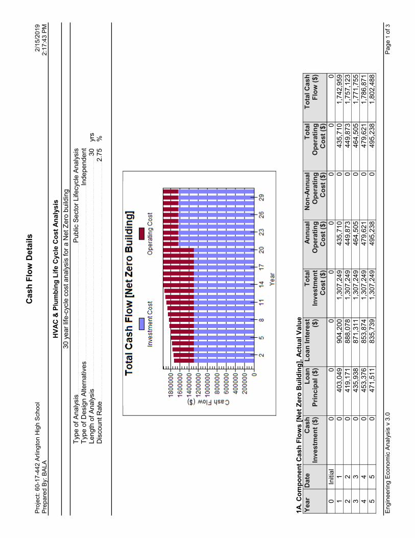
C
as
h F
low
De
tail
sP
roje
ct:
60
-17
-44
2 A
rlin
gto
n H
igh
Sch
oo
l 2
/15
/20
19
Pre
pa
red
By:
BA
LA
2
:17
:43
PM
HV
AC
& P
lum
bin
g L
ife C
ycle
Co
st
An
aly
sis
30 y
ear
life-c
ycle
cost analy
sis
for
a N
et Z
ero
build
ing
Type o
f A
naly
sis
Public
Secto
r Lifecycle
Analy
sis
Type o
f D
esig
n A
ltern
atives
Independent
Length
of
Analy
sis
30
yrs
Dis
count R
ate
2.7
5
%
1A
. C
om
po
nen
t C
ash
Flo
ws [
Net
Zero
Bu
ild
ing
], A
ctu
al V
alu
eY
ear
Date
Cash
In
vestm
en
t ($
)L
oan
P
rin
cip
al ($
)L
oan
In
tere
st
($)
To
tal
Inv
estm
en
t C
ost
($)
An
nu
al
Op
era
tin
g
Co
st
($)
No
n-A
nn
ual
Op
era
tin
g
Co
st
($)
To
tal
Op
era
tin
g
Co
st
($)
To
tal C
ash
F
low
($)
0In
itia
l0
00
00
00
0
11
0403,0
49
904,2
00
1,3
07,2
49
435,7
10
0435,7
10
1,7
42,9
59
22
0419,1
71
888,0
78
1,3
07,2
49
449,8
73
0449,8
73
1,7
57,1
23
33
0435,9
38
871,3
11
1,3
07,2
49
464,5
05
0464,5
05
1,7
71,7
55
44
0453,3
76
853,8
74
1,3
07,2
49
479,6
21
0479,6
21
1,7
86,8
71
55
0471,5
11
835,7
39
1,3
07,2
49
495,2
38
0495,2
38
1,8
02,4
88
En
gin
ee
rin
g E
co
no
mic
An
aly
sis
v 3
.0P
ag
e 1
of
3

C
as
h F
low
De
tail
sP
roje
ct:
60
-17
-44
2 A
rlin
gto
n H
igh
Sch
oo
l 2
/15
/20
19
Pre
pa
red
By:
BA
LA
2
:17
:43
PM
Year
Date
Cash
In
vestm
en
t ($
)L
oan
P
rin
cip
al ($
)L
oan
In
tere
st
($)
To
tal
Inv
estm
en
t C
ost
($)
An
nu
al
Op
era
tin
g
Co
st
($)
No
n-A
nn
ual
Op
era
tin
g
Co
st
($)
To
tal
Op
era
tin
g
Co
st
($)
To
tal C
ash
F
low
($)
66
0490,3
71
816,8
78
1,3
07,2
49
511,3
73
0511,3
73
1,8
18,6
22
77
0509,9
86
797,2
63
1,3
07,2
49
528,0
43
0528,0
43
1,8
35,2
92
88
0530,3
86
776,8
64
1,3
07,2
49
545,2
66
0545,2
66
1,8
52,5
15
99
0551,6
01
755,6
48
1,3
07,2
49
563,0
61
0563,0
61
1,8
70,3
10
10
10
0573,6
65
733,5
84
1,3
07,2
49
581,4
47
0581,4
47
1,8
88,6
97
11
11
0596,6
12
710,6
38
1,3
07,2
49
600,4
45
0600,4
45
1,9
07,6
94
12
12
0620,4
76
686,7
73
1,3
07,2
49
620,0
75
0620,0
75
1,9
27,3
24
13
13
0645,2
95
661,9
54
1,3
07,2
49
640,3
58
0640,3
58
1,9
47,6
07
14
14
0671,1
07
636,1
43
1,3
07,2
49
661,3
17
0661,3
17
1,9
68,5
66
15
15
0697,9
51
609,2
98
1,3
07,2
49
682,9
75
0682,9
75
1,9
90,2
24
16
16
0725,8
69
581,3
80
1,3
07,2
49
705,3
55
0705,3
55
2,0
12,6
04
17
17
0754,9
04
552,3
45
1,3
07,2
49
728,4
82
0728,4
82
2,0
35,7
32
18
18
0785,1
00
522,1
49
1,3
07,2
49
752,3
82
0752,3
82
2,0
59,6
31
19
19
0816,5
04
490,7
45
1,3
07,2
49
777,0
81
0777,0
81
2,0
84,3
30
20
20
0849,1
64
458,0
85
1,3
07,2
49
802,6
05
0802,6
05
2,1
09,8
55
21
21
01,0
77,3
00
561,6
19
1,6
38,9
19
828,9
84
0828,9
84
2,4
67,9
03
22
22
01,1
23,3
05
515,6
14
1,6
38,9
19
856,2
46
0856,2
46
2,4
95,1
65
23
23
01,1
71,3
10
467,6
09
1,6
38,9
19
884,4
22
0884,4
22
2,5
23,3
41
24
24
01,2
21,4
04
417,5
15
1,6
38,9
19
913,5
43
0913,5
43
2,5
52,4
61
25
25
01,2
73,6
80
365,2
39
1,6
38,9
19
943,6
40
0943,6
40
2,5
82,5
59
26
26
01,3
28,2
35
310,6
83
1,6
38,9
19
974,7
49
0974,7
49
2,6
13,6
68
27
27
01,3
85,1
71
253,7
47
1,6
38,9
19
1,0
06,9
02
01,0
06,9
02
2,6
45,8
21
28
28
01,4
44,5
94
194,3
25
1,6
38,9
19
1,0
40,1
37
01,0
40,1
37
2,6
79,0
56
29
29
01,5
06,6
15
132,3
04
1,6
38,9
19
1,0
74,4
90
01,0
74,4
90
2,7
13,4
08
30
30
01,5
71,3
49
67,5
70
1,6
38,9
19
1,1
09,9
99
01,1
09,9
99
2,7
48,9
18
Tota
ls
025,1
04,9
99
17,4
29,1
74
42,5
34,1
70
21,6
58,3
24
021,6
58,3
24
64,1
92,4
99
1B
. P
resen
t W
ort
h C
ash
Flo
ws [
Net
Zero
Bu
ild
ing
]Y
ear
Date
To
tal In
vestm
en
t C
ost
($)
To
tal O
pera
tin
g C
ost
($)
To
tal P
resen
t W
ort
h
($)
0In
itia
l0
00
11
1,2
72,2
62
424,0
49
1,6
96,3
11
22
1,2
38,2
11
426,1
15
1,6
64,3
26
33
1,2
05,0
72
428,1
98
1,6
33,2
70
44
1,1
72,8
19
430,3
00
1,6
03,1
19
55
1,1
41,4
30
432,4
19
1,5
73,8
49
66
1,1
10,8
81
434,5
57
1,5
45,4
38
En
gin
ee
rin
g E
co
no
mic
An
aly
sis
v 3
.0P
ag
e 2
of
3

C
as
h F
low
De
tail
sP
roje
ct:
60
-17
-44
2 A
rlin
gto
n H
igh
Sch
oo
l 2
/15
/20
19
Pre
pa
red
By:
BA
LA
2
:17
:43
PM
Year
Date
To
tal In
vestm
en
t C
ost
($)
To
tal O
pera
tin
g C
ost
($)
To
tal P
resen
t W
ort
h
($)
77
1,0
81,1
49
436,7
13
1,5
17,8
62
88
1,0
52,2
13
438,8
88
1,4
91,1
01
99
1,0
24,0
52
441,0
82
1,4
65,1
33
10
10
996,6
44
443,2
94
1,4
39,9
38
11
11
969,9
70
445,5
26
1,4
15,4
96
12
12
944,0
10
447,7
77
1,3
91,7
87
13
13
918,7
44
450,0
48
1,3
68,7
92
14
14
894,1
55
452,3
39
1,3
46,4
94
15
15
870,2
24
454,6
50
1,3
24,8
74
16
16
846,9
33
456,9
81
1,3
03,9
15
17
17
824,2
66
459,3
33
1,2
83,5
99
18
18
802,2
05
461,7
06
1,2
63,9
11
19
19
780,7
35
464,1
00
1,2
44,8
35
20
20
759,8
39
466,5
15
1,2
26,3
54
21
21
927,1
27
468,9
51
1,3
96,0
78
22
22
902,3
13
471,4
10
1,3
73,7
22
23
23
878,1
63
473,8
90
1,3
52,0
53
24
24
854,6
60
476,3
92
1,3
31,0
53
25
25
831,7
86
478,9
18
1,3
10,7
04
26
26
809,5
24
481,4
65
1,2
90,9
90
27
27
787,8
58
484,0
36
1,2
71,8
94
28
28
766,7
72
486,6
30
1,2
53,4
02
29
29
746,2
50
489,2
48
1,2
35,4
98
30
30
726,2
77
491,8
90
1,2
18,1
67
Tota
ls
28,1
36,5
44
13,6
97,4
20
41,8
33,9
65
En
gin
ee
rin
g E
co
no
mic
An
aly
sis
v 3
.0P
ag
e 3
of
3

Study InputsProject: 60-17-442 Arlington High School 2/15/2019Prepared By: BALA 2:17:43 PM
Study Title HVAC & Plumbing Life Cycle Cost Analysis
Study Description :30 year life-cycle cost analysis for a Net Zero building
Type of Analysis Public Sector Lifecycle Analysis
Type of Design Alternatives Independent
Base Year 1
Currency Symbol $
Length of Analysis 30 yrs Discount Rate 2.75 %
Engineering Economic Analysis v 3.0 Page 1 of 1

Design Case InputsProject: 60-17-442 Arlington High School 2/15/2019Prepared By: BALA 2:17:44 PM
Type of Analysis Public Sector Lifecycle Analysis
Length of Analysis 30 yrs Income Taxes Not Considered
General Information :
Design Case Name Net Zero BuildingDesign Case Short Name NetZeroDescription :
Building with Geothermal HVAC
Investment Costs :Cost Item Cost ($) Year Incurred Esc Rate
(%/yr)Salvage Value
($)Useful Life
(yrs)
HVAC Cost 1 $ 4,499,442 0 0.00 $ 0 30HVAC Cost 2 $ 4,499,442 0 0.00 $ 0 30HVAC Cost 3 $ 4,499,442 0 0.00 $ 0 30HVAC Cost 4 $ 4,499,442 0 0.00 $ 0 30Plumbing Cost 1 $ 4,607,232 0 0.00 $ 0 30Partial System Replacement Cost $ 2,500,000 20 0.00 $ 0 10
Loans :Loan Item Start Year Investment
In Start Year ($)
Percent Financed
Term Of Loan (Years)
Interest Rate (%/yr)
Payment Method
Municipal Bond Financing for NZB
0 $ 25,105,000 100 30 4.00 Equal Payments
Replacement Cost Financing
20 $ 25,105,000 100 10 5.50 Equal Payments
Annual Operating Costs :Cost Item Cost ($) Start Year Number Of Years Esc Rate (%/yr)
Annual HVAC & Plumbing Energy Cost $ 317,000 1 30 3.00Annual Maintenance Costs $ 105,000 1 30 4.00
There are no non-annual operating cost inputs
Engineering Economic Analysis v 3.0 Page 1 of 1


HEATING, VENTILATING AND AIR CONDITIONING
230000 - 1
ARLINGTON HIGH SCHOOL
HEATING, VENTILATING AND AIR CONDITIONING BUILDING SYSTEMS
SCHEMATIC DESIGN NARRATIVE
A. General:
1. This proposed HVAC system is based on a geothermal (geo-exchange) system where all cooling and heating for the building is provided by a ground loop geothermal system.
2. The new building construction is to be built in three phases from south to north with the existing building largely remaining in operation initially and then being phased out after the initial phase is complete. Demolition of the existing building will initiate after the first phase of new construction is complete. The geothermal borehole well field for the entire heating/cooling system will be constructed over all three phases.
3. All work shall be constructed in compliance with the requirements of the 9th Edition of the Massachusetts Building Code/2015 International Building Code with amendments including the 2015 International Energy Code and the 2015 International Mechanical Code.
4. The building design will include features meeting the criteria for LEED for Schools Silver certification at a minimum.
5. Heating, air conditioning and ventilation systems shall be high-efficiency systems that allow for the ability towards achieving a Net Zero Energy facility.
6. Heating, air conditioning and ventilation systems shall be high-efficiency systems exceeding MSBA Sustainable Building Design Guidelines exceeding the level of energy efficiency required by the current MA Energy Code (ASHRAE 90.1-2013) by 20%.
B. Ground Loop Geo-Exchange System:
1. A vertical borehole well field area consisting of (400) 6 inch diameter boreholes spaced 20 feet apart shall be provided based on preliminary building heating/cooling estimations. Each borehole shall be 400 to 500 feet deep with the anticipated energy transfer of 2 to 3 tons (24,000 – 36,000 Btuh). Wells are comprised of a few separate groups and installation will be staggered to support a phased construction approach. Actual depth to be determined based on thermal conductivity testing performed on a test well. The number of boreholes may be increased or decreased based on thermal testing results and/or determination of the final heating and cooling loads which will be concluded during Design Development phase of Project.
2. Analysis shall be performed to determine the number and depth of closed loop wells based on available geological and hydrological information and the energy model findings. Test wells will be 500-foot deep and provide thermal conductivity, thermal diffusivity, and soil temperature; water flow rates; soil composition; and formation types encountered, depths, and water zones. From this information, geothermal well field bore spacing, location, and depth of closed-loop geothermal wells and size and piping of horizontal piping from the well field to the plant will be determined.
3. Provide a 1-1/4 inch supply and return pipe within each borehole with a U-bend at the bottom. Piping shall be high density polyethylene (HDPE) with DR9 wall thickness.
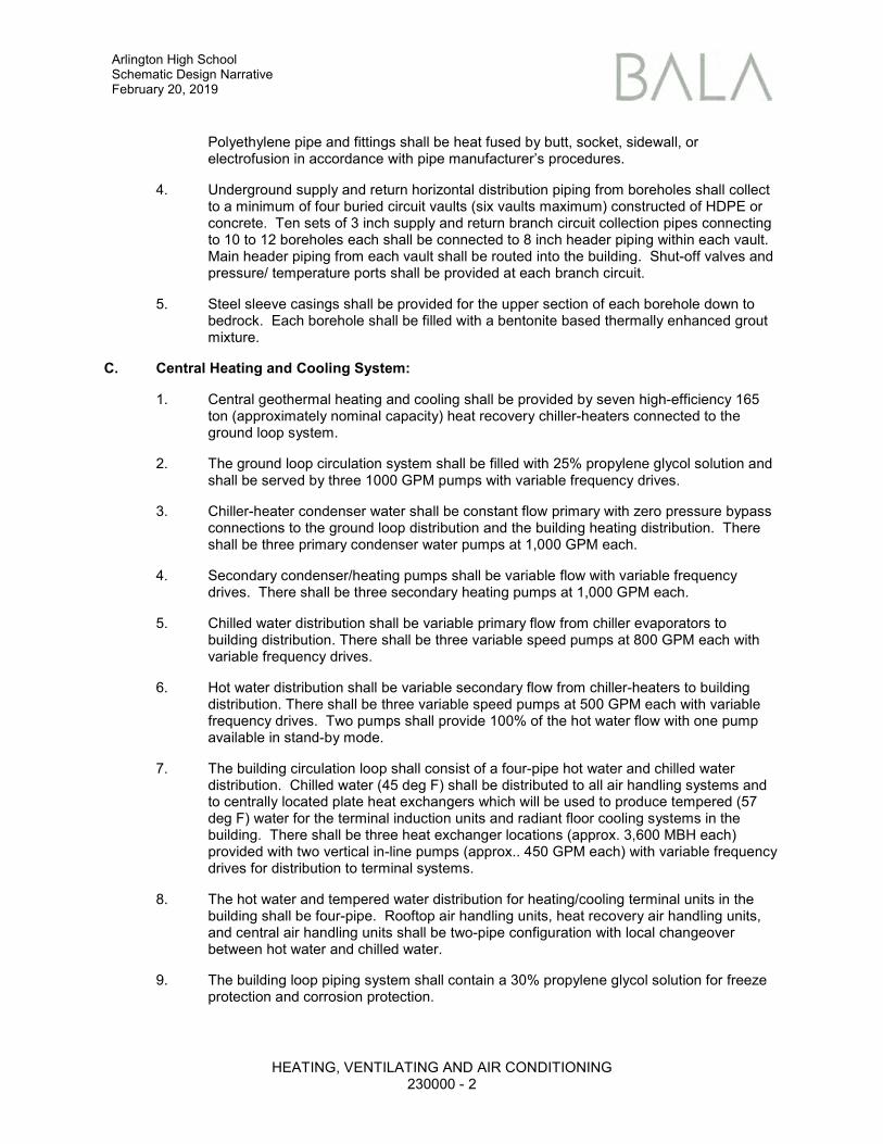
Arlington High School Schematic Design Narrative February 20, 2019
HEATING, VENTILATING AND AIR CONDITIONING
230000 - 2
Polyethylene pipe and fittings shall be heat fused by butt, socket, sidewall, or electrofusion in accordance with pipe manufacturer’s procedures.
4. Underground supply and return horizontal distribution piping from boreholes shall collect to a minimum of four buried circuit vaults (six vaults maximum) constructed of HDPE or concrete. Ten sets of 3 inch supply and return branch circuit collection pipes connecting to 10 to 12 boreholes each shall be connected to 8 inch header piping within each vault. Main header piping from each vault shall be routed into the building. Shut-off valves and pressure/ temperature ports shall be provided at each branch circuit.
5. Steel sleeve casings shall be provided for the upper section of each borehole down to bedrock. Each borehole shall be filled with a bentonite based thermally enhanced grout mixture.
C. Central Heating and Cooling System:
1. Central geothermal heating and cooling shall be provided by seven high-efficiency 165 ton (approximately nominal capacity) heat recovery chiller-heaters connected to the ground loop system.
2. The ground loop circulation system shall be filled with 25% propylene glycol solution and shall be served by three 1000 GPM pumps with variable frequency drives.
3. Chiller-heater condenser water shall be constant flow primary with zero pressure bypass connections to the ground loop distribution and the building heating distribution. There shall be three primary condenser water pumps at 1,000 GPM each.
4. Secondary condenser/heating pumps shall be variable flow with variable frequency drives. There shall be three secondary heating pumps at 1,000 GPM each.
5. Chilled water distribution shall be variable primary flow from chiller evaporators to building distribution. There shall be three variable speed pumps at 800 GPM each with variable frequency drives.
6. Hot water distribution shall be variable secondary flow from chiller-heaters to building distribution. There shall be three variable speed pumps at 500 GPM each with variable frequency drives. Two pumps shall provide 100% of the hot water flow with one pump available in stand-by mode.
7. The building circulation loop shall consist of a four-pipe hot water and chilled water distribution. Chilled water (45 deg F) shall be distributed to all air handling systems and to centrally located plate heat exchangers which will be used to produce tempered (57 deg F) water for the terminal induction units and radiant floor cooling systems in the building. There shall be three heat exchanger locations (approx. 3,600 MBH each) provided with two vertical in-line pumps (approx.. 450 GPM each) with variable frequency drives for distribution to terminal systems.
8. The hot water and tempered water distribution for heating/cooling terminal units in the building shall be four-pipe. Rooftop air handling units, heat recovery air handling units, and central air handling units shall be two-pipe configuration with local changeover between hot water and chilled water.
9. The building loop piping system shall contain a 30% propylene glycol solution for freeze protection and corrosion protection.

Arlington High School Schematic Design Narrative February 20, 2019
HEATING, VENTILATING AND AIR CONDITIONING
230000 - 3
10. The building terminal heating units will be designed to utilize low temperature heating supply water (130°F maximum). Heating terminal units such as fin tube radiation and heating coils may require larger surface areas due to the low water temperature. In areas with high heating loads, radiant floor pipe circuits, two-row fin-tube, or heating coils will be required.
D. Exterior Classrooms - Chilled Beam Units:
1. The system serving heating, cooling, and ventilation for typical exterior classrooms shall utilize four-pipe ceiling mounted active chilled beam units. Chilled beams will be provided with ventilation air from a rooftop energy recovery ventilation unit. Two 8 foot long units shall be provided for each typical classroom mounted parallel to exterior wall. Each unit shall be served by a single 7 inch diameter primary ventilation supply air ducts downstream of a single duct variable air volume terminal box.
2. The primary supply air serving each classroom shall be provided with a modulating supply air single duct variable air volume terminal with hot water heating coil to control supply air volume and temperature when the room is occupied.
3. Systems will be interfaced to the local space vacancy sensor to reduce ventilation air and reset the space cooling and heating set point temperatures when the room is unoccupied.
4. A carbon dioxide sampling sensing system will be provided in classrooms to provide monitoring and occupied control of ventilation air.
E. Interior Classrooms and Other Spaces – Chilled Beam Units:
1. Interior classrooms and other interior occupied spaces will be served with ventilation supply air from a rooftop heat recovery ventilation unit connected to ceiling mounted chilled beam units. Chilled beams shall be provided with four-pipe heating/cooling supply and return water connections.
2. Primary ventilation supply air to individual classrooms shall be provided with a supply air single duct variable air volume terminal box with hot water coil to control ventilation air volume when the room is occupied.
3. Exhaust air from each classroom shall be controlled by a single duct variable air volume exhaust terminal to track the supply air to the room and maintain a neutral pressure balance.
4. Systems will be interfaced to the local space vacancy sensor to reduce ventilation air and reset the space cooling and heating set point temperatures when the room is unoccupied.
5. A carbon dioxide sampling sensing system shall be provided for classrooms to monitor and control ventilation air.
F. Classroom and Interior Ventilation Systems:
1. Outside ventilation air for classrooms and interior spaces will be provided dedicated outside air heat recovery units (HRU) located on various roof wings.
2. The HRU's will be variable air volume and will include supply and exhaust fans with variable frequency drives, and total energy recovery wheels. The units will be provided with four-pipe hot water and chilled water system connections to individual pre-heat and cooling coil. Each unit shall include 100% recirculation dampers for morning warm-up mode and after-hours night setback heating.

Arlington High School Schematic Design Narrative February 20, 2019
HEATING, VENTILATING AND AIR CONDITIONING
230000 - 4
3. All unit total energy recovery wheels and coils shall be sized for low face velocity/ low pressure drop to increase unit and system efficiency.
4. Variable supply air provided by the HRU will be based on demand from classrooms and interior spaces. Variable return/exhaust air shall be provided by air flow control terminals which shall track the supply air.
5. Classroom corridors will be provided with ventilation air from the HRU system. Air quantities more than basic ventilation requirements will be provided for building exhaust makeup air as required. Corridors will not be fully air conditioned except for areas that have direct solar loads.
G. Gymnasium:
1. Space shall be served with two outside air heat recovery units (HRU). Units will be variable air volume with variable frequency drives on supply fans, MERV 8 and MERV 13 filters and total energy recovery wheels. The units will be provided with four-pipe hot water and chilled water system connections to individual heating and cooling coils. Each unit shall include 100% recirculation dampers for morning warm-up mode and after-hours night setback heating.
2. Two units shall be provided, which shall be located indoors or outdoors depending on structural and architectural requirements. Round ductwork from units will be exposed within the space for air distribution.
3. Two new roof mounted relief vents shall be provided on gym roof. Vents will have barometric dampers to relieve space pressure.
4. Ceiling fans will be hung from space structure to allow for destratification of space temperature and convection cooling. There will be six fans each with a diameter of 16 feet-0 inch controlled by high and low space temperature sensors.
H. Stadium Toilet Facility:
1. Remote structure shall be heated using electric fan driven wall heaters with integral thermostats. Each space shall have a temperature sensor connected to central ATC system for monitoring.
2. Toilet rooms will be exhausted by ductwork and inline fans with make-up air from transfer ducts.
I. Dedicated Air Handling Systems:
1. All normally occupied areas will be fully air conditioned except for corridors, the kitchen, and culinary classrooms with kitchen hoods (if applicable). The kitchen and culinary areas are partially conditioned by makeup air units and tempered with the use of transfer air from the commons area.
2. The Auditorium, Stage, Band/Chorus, and Black Box will be served by rooftop dedicated outside air heat recovery units (HRU). Separate occupancy scheduling for each unit will be provided for operational flexibility.
3. Rooftop heat recovery units (HRU) will include total energy recovery wheels, supply fan, return fan (if required), hot water heating/chilled water cooling coils, MERV 8 and MERV 13 filters, and variable frequency drives. Unit serving Band/Chorus will be variable air volume (VAV) with local variable air volume boxes for zone temperature control.

Arlington High School Schematic Design Narrative February 20, 2019
HEATING, VENTILATING AND AIR CONDITIONING
230000 - 5
4. The Auditorium, Stage, Gymnasium and Black Box units will be single zone with a variable frequency drive to modulate the supply air during periods of low demand and occupancy.
5. The Auditorium, Stage, Gymnasium, Commons, Band/Chorus and Black Box systems will be provided with space carbon dioxide (CO2) sensors to provide modulation of outside air based on occupancy demand.
J. Variable Refrigerant Flow (VRF) Systems:
1. School Administration as well as Day Care/Pre-school areas will each be served by refrigerant heating/cooling VRF fan coil units. Spaces will be provided with ventilation and exhaust air from single duct variable air volume terminal boxes from a rooftop energy recovery ventilation unit. Ventilation air for as many as three spaces will be served by one single duct terminal box. One one-ton ceiling mounted fan coil unit shall be provided for each space with as many as three spaces under 150 SF served by one unit. Each unit shall be served by a set of 1/2 inch refrigerant pipes from a branch selector box.
K. Radiant Floor Systems:
1. Double height common areas and open group learning spaces will be provided with a radiant floor cooling and heating system to provide either full or partial cooling and heating. System shall include connections to the hot water and tempered chilled water piping, circulation pumps, circuit headers, controls, and under-slab PEX piping distribution.
L. Duct Collector:
1. Provide downflow type with capacity of 4,000 cfm at a static pressure of 5 inch w.g.
2. Unit provided with sound attenuators on inlet and outlet air ports and ducted to various machines with 4 inch round branches. Ductwork shall be high pressure stainless steel with welded seams.
M. Science Room Hood Exhaust Fans:
1. Provide high plume laboratory exhaust fan mounted on roof curb. Fan shall be high velocity with discharge nozzles and integral sound attenuator.
2. Stainless steel ductwork shall connect to fume hood and terminate at roof fan.
N. Carbon Monoxide Detection:
1. CO detection system shall be provided in Science Rooms and Kitchen and tied back to BMD and fire alarm system.
O. Stair Pressurization Fan:
1. Provide roof mounted supply with capacity of 5,000 CFM at a static pressure of 3 inch w.g.
2. Fan shall be aluminum and mounted on roof curb above stair. Fan’s direct drive fan shall have variable frequency drive wired to pressure sensor in stair.
3. As part of system, roof mounted relief vent shall be provided with barometric and isolation damper.

Arlington High School Schematic Design Narrative February 20, 2019
HEATING, VENTILATING AND AIR CONDITIONING
230000 - 6
P. Tel/Data Air Conditioning Units:
1. Tel/Data Room shall be provided with 2 ton wall mounted spilt air conditioning units. Units shall be connected to a single outdoor roof mounted condensing with capacity of 12 tons. There will be three of these systems to serve different building segments.
Q. Building Management System (BMS):
1. Provide direct digital control (DDC) BMS with local and unitary controls and web interface for remote access, alarms, and monitoring of all HVAC equipment in the building including: chillers, pumps, heat recovery units, rooftop units, fans, and terminal units shall be controlled and mapped to a central monitoring station. System shall be based on the Niagara Framework open protocol for interoperability between manufacturers.
2. BMS system shall be interfaced to the building electrical and domestic water sub-meters. Daily, weekly, and annual energy use shall be reported for each meter.
3. BMS system shall contain separate BACnet IP addresses at each of the main control panel wired back to a central location. The IP address shall be used to transmit equipment and system information to an offsite third-party commissioning agency for continuous metering, diagnostics and point trending. Software shall be propriety and provided by Iconics.
R. Carbon Dioxide Sensing System:
1. Provide an Aircuity, or equal, carbon dioxide air sampling and sensing system consisting of room sensors, cabling, tubing, room probes, air routers, and vacuum pumps.
2. Air tubing from room sensors shall be collected through air routers to sensing stations.
3. The system shall include an information management system and shall be integration with the building management system.
4. Building management system input shall provide control input for modulating supply air terminal units or automatic dampers.
S. Electrical and BTU Metering:
1. Electrical metering shall be provided for collection of historical and real-time performance data. Separate meter groups shall be provided for the upper school areas and lower school areas consisting of meters for the measurement of lighting and plug loads for each classroom group by wing, floor or classroom type.
2. Individual metering of lighting and plug loads shall be provided for the Kitchen, Media Center, Auditorium/Stage, Gymnasium, and Administration areas.
3. Electrical metering shall be provided for each air handling system, central system pumps (by each group type), and each chiller-heater.
4. Provide BTU metering of chilled water, hot water, ground loop circulation systems and domestic hot water system.
T. Phasing Considerations:
1. Construction of the new facility is in three phases (Phases 1, 2, and 3). Phase 1 of construction allows for the existing building to remain occupied, while a large part of the

Arlington High School Schematic Design Narrative February 20, 2019
HEATING, VENTILATING AND AIR CONDITIONING
230000 - 7
new construction is completed. Therefore, the existing boiler room must remain active during Phase 1 and half of the new chiller-heater plant must be constructed to support the new construction. Approximately 3,000 SF of new mechanical space will be needed for the new central plant.
2. Construction phasing will allow the geothermal borehole field to be installed intermittently in all three phases.
3. Commissioning of complete and partial HVAC systems shall take place prior to each construction Phase closeout. Commissioning shall include changing of air filters, balancing of all air and water system as well as adjusting control sequences and set points.
U. Future Expansion Considerations:
1. As part of a proposed future academic expansion of STEAM Wing on the second, third, fourth, and fifth floors, new central heating and cooling systems as well as air handling units shall be designed for additional capacity. Heating and cooling hydronic piping along with ventilation and exhaust ductwork shall be capped on all floors anticipating future expansion. Capped HVAC services will be labeled with design capacities.
V. Swing Space in Existing School
1. Phase 1 First Floor Classroom will be subdivided into temporary High School Administration, Nurse and Register spaces. Spaces will be served with heating and ventilation from a combination of existing and new unit ventilators. Unit ventilators shall utilize existing steam service in crawl space.
2. Phase 2 Second Floor History Classrooms will be subdivision into temporary High School offices and conference room spaces. Exterior spaces will be served with heating and ventilation from existing unit ventilators. Interior spaces will be served by a new split refrigerant air conditioning system.
3. Phase 2 Second Floor Blue Gym will be temporarily repurposed for Cafeteria and kitchen services. Kitchen hood exhaust fans will be provided and existing air handling units shall be modified for ventilation and heating space requirements.
4. Phase 2 Third Floor Old Hall and Classrooms will be temporarily repurposed for Library Program Function space. Spaces will be served with heating and ventilation from existing unit ventilators and air handling units. Existing units shall be modified for ventilation and heating space requirements.
5. Phase 3 First Floor History Shower Bank will be subdivision into temporary Locker Rooms. Spaces will be served with heating and ventilation from existing unit ventilators. Existing units shall be modified for ventilation and heating space requirements.
H:\60-17-442\ADMIN - Arlington High School\ADDENDUMS-BULLETINS-NARRATIVES\17-442-007-HVAC SD Narrative.docx


B A L A C O N S U L T I N G E N G I N E E R S 617 357 6060
52 TEMPLE PLACE 617 357 5188 FAX
BOSTON, MA 02111 WWW.BALA.COM
February 15, 2019
Arlington High School Life-Cycle Cost Estimate Project # 60-17-442
Included herein is a life cycle cost estimate for the new Arlington High School in accordance with the requirements of MGL Chapter 149 Section 44M guidelines.
The following qualifications and assumptions were used in preparing this report:
1. The Town's portion of the HVAC and Plumbing construction cost is included as the initial cost. This is assumed to be $22,605,000 or 70% of the construction cost. An additional partial system replacement cost of $2,500,000 after year 20 was included as well.
2. It is assumed that the Town's initial cost will be paid in the form of a municipal bond over a period of 30 years. The interest rate used to determine annual payments is based on 4.0%. The actual rate may differ.
3. Cash flow details are provided for payments based on equal payments.
4. Estimated annual HVAC & Plumbing energy costs along with outside maintenance costs are included. Salaries for maintenance and operations, supplies, replacement costs, residual values or water costs are not included.
5. Outside maintenance and repair cost is an estimate based on the building size and industry averages. Actual cost will depend on a final negotiated annual maintenance and service contract with a third party following the completion of construction. Approximately $0.25 per square foot is included.
6. Annual electricity energy cost from Energy Model was included due to the uncertainty surrounding site availability and required quantity of photovoltaic. Escalation for electricity is assumed to be 3.0%. Government baseline projections of cost escalation for this energy source are below this, but worst-case projections could be higher than 3%.
7. The discount rate used is 2.75% assuming funds will be borrowed for investment by issuing bonds. Discount rate would match interest rate paid for bonds.
8. All dollar values are in present worth dollars with no adjustment for inflation.
Please note that this is only an estimate and does not represent actual projected costs. Results will vary based on actual building use, interest rates, and escalation rates.
Prepared by: Bala Consulting Engineers J. Ryan Flynn, P.E. cc: KJC H:\60-17-442\DESIGN WORK\HVAC DESIGN\Life Cycle Cost Analysis\2019.02.14 Life Cycle Cost Estimate.docx

Lifecycle SummaryProject: 60-17-442 Arlington High School 2/15/2019Prepared By: BALA 2:17:43 PM
HVAC & Plumbing Life Cycle Cost Analysis
30 year life-cycle cost analysis for a Net Zero building
Type of Analysis Public Sector Lifecycle Analysis
Type of Design Alternatives Independent
Length of Analysis 30 yrs Discount Rate 2.75 %
Table 1. Executive Summary
Economic Criteria Best Design Case for Each Criteria Value ($)
Lowest Total Present Worth Net Zero Building $41,833,967
Lowest Annual Operating Cost Net Zero Building $422,000
Lowest First Cost Net Zero Building $22,605,000
Table 2. Design Cases Ranked by Total Present WorthDesign Case Name Design Case
Short NameTotal Present
Worth ($)Annual Operating
Cost ($/yr)First Cost ($)
Net Zero Building NetZero $41,833,967 $422,000 $22,605,000
Engineering Economic Analysis v 3.0 Page 1 of 1

C
as
h F
low
De
tail
sP
roje
ct:
60
-17
-44
2 A
rlin
gto
n H
igh
Sch
oo
l 2
/15
/20
19
Pre
pa
red
By:
BA
LA
2
:17
:43
PM
HV
AC
& P
lum
bin
g L
ife C
ycle
Co
st
An
aly
sis
30 y
ear
life-c
ycle
cost analy
sis
for
a N
et Z
ero
build
ing
Type o
f A
naly
sis
Public
Secto
r Lifecycle
Analy
sis
Type o
f D
esig
n A
ltern
atives
Independent
Length
of
Analy
sis
30
yrs
Dis
count R
ate
2.7
5
%
1A
. C
om
po
nen
t C
ash
Flo
ws [
Net
Zero
Bu
ild
ing
], A
ctu
al V
alu
eY
ear
Date
Cash
In
vestm
en
t ($
)L
oan
P
rin
cip
al ($
)L
oan
In
tere
st
($)
To
tal
Inv
estm
en
t C
ost
($)
An
nu
al
Op
era
tin
g
Co
st
($)
No
n-A
nn
ual
Op
era
tin
g
Co
st
($)
To
tal
Op
era
tin
g
Co
st
($)
To
tal C
ash
F
low
($)
0In
itia
l0
00
00
00
0
11
0403,0
49
904,2
00
1,3
07,2
49
435,7
10
0435,7
10
1,7
42,9
59
22
0419,1
71
888,0
78
1,3
07,2
49
449,8
73
0449,8
73
1,7
57,1
23
33
0435,9
38
871,3
11
1,3
07,2
49
464,5
05
0464,5
05
1,7
71,7
55
44
0453,3
76
853,8
74
1,3
07,2
49
479,6
21
0479,6
21
1,7
86,8
71
55
0471,5
11
835,7
39
1,3
07,2
49
495,2
38
0495,2
38
1,8
02,4
88
En
gin
ee
rin
g E
co
no
mic
An
aly
sis
v 3
.0P
ag
e 1
of
3

C
as
h F
low
De
tail
sP
roje
ct:
60
-17
-44
2 A
rlin
gto
n H
igh
Sch
oo
l 2
/15
/20
19
Pre
pa
red
By:
BA
LA
2
:17
:43
PM
Year
Date
Cash
In
vestm
en
t ($
)L
oan
P
rin
cip
al ($
)L
oan
In
tere
st
($)
To
tal
Inv
estm
en
t C
ost
($)
An
nu
al
Op
era
tin
g
Co
st
($)
No
n-A
nn
ual
Op
era
tin
g
Co
st
($)
To
tal
Op
era
tin
g
Co
st
($)
To
tal C
ash
F
low
($)
66
0490,3
71
816,8
78
1,3
07,2
49
511,3
73
0511,3
73
1,8
18,6
22
77
0509,9
86
797,2
63
1,3
07,2
49
528,0
43
0528,0
43
1,8
35,2
92
88
0530,3
86
776,8
64
1,3
07,2
49
545,2
66
0545,2
66
1,8
52,5
15
99
0551,6
01
755,6
48
1,3
07,2
49
563,0
61
0563,0
61
1,8
70,3
10
10
10
0573,6
65
733,5
84
1,3
07,2
49
581,4
47
0581,4
47
1,8
88,6
97
11
11
0596,6
12
710,6
38
1,3
07,2
49
600,4
45
0600,4
45
1,9
07,6
94
12
12
0620,4
76
686,7
73
1,3
07,2
49
620,0
75
0620,0
75
1,9
27,3
24
13
13
0645,2
95
661,9
54
1,3
07,2
49
640,3
58
0640,3
58
1,9
47,6
07
14
14
0671,1
07
636,1
43
1,3
07,2
49
661,3
17
0661,3
17
1,9
68,5
66
15
15
0697,9
51
609,2
98
1,3
07,2
49
682,9
75
0682,9
75
1,9
90,2
24
16
16
0725,8
69
581,3
80
1,3
07,2
49
705,3
55
0705,3
55
2,0
12,6
04
17
17
0754,9
04
552,3
45
1,3
07,2
49
728,4
82
0728,4
82
2,0
35,7
32
18
18
0785,1
00
522,1
49
1,3
07,2
49
752,3
82
0752,3
82
2,0
59,6
31
19
19
0816,5
04
490,7
45
1,3
07,2
49
777,0
81
0777,0
81
2,0
84,3
30
20
20
0849,1
64
458,0
85
1,3
07,2
49
802,6
05
0802,6
05
2,1
09,8
55
21
21
01,0
77,3
00
561,6
19
1,6
38,9
19
828,9
84
0828,9
84
2,4
67,9
03
22
22
01,1
23,3
05
515,6
14
1,6
38,9
19
856,2
46
0856,2
46
2,4
95,1
65
23
23
01,1
71,3
10
467,6
09
1,6
38,9
19
884,4
22
0884,4
22
2,5
23,3
41
24
24
01,2
21,4
04
417,5
15
1,6
38,9
19
913,5
43
0913,5
43
2,5
52,4
61
25
25
01,2
73,6
80
365,2
39
1,6
38,9
19
943,6
40
0943,6
40
2,5
82,5
59
26
26
01,3
28,2
35
310,6
83
1,6
38,9
19
974,7
49
0974,7
49
2,6
13,6
68
27
27
01,3
85,1
71
253,7
47
1,6
38,9
19
1,0
06,9
02
01,0
06,9
02
2,6
45,8
21
28
28
01,4
44,5
94
194,3
25
1,6
38,9
19
1,0
40,1
37
01,0
40,1
37
2,6
79,0
56
29
29
01,5
06,6
15
132,3
04
1,6
38,9
19
1,0
74,4
90
01,0
74,4
90
2,7
13,4
08
30
30
01,5
71,3
49
67,5
70
1,6
38,9
19
1,1
09,9
99
01,1
09,9
99
2,7
48,9
18
Tota
ls
025,1
04,9
99
17,4
29,1
74
42,5
34,1
70
21,6
58,3
24
021,6
58,3
24
64,1
92,4
99
1B
. P
resen
t W
ort
h C
ash
Flo
ws [
Net
Zero
Bu
ild
ing
]Y
ear
Date
To
tal In
vestm
en
t C
ost
($)
To
tal O
pera
tin
g C
ost
($)
To
tal P
resen
t W
ort
h
($)
0In
itia
l0
00
11
1,2
72,2
62
424,0
49
1,6
96,3
11
22
1,2
38,2
11
426,1
15
1,6
64,3
26
33
1,2
05,0
72
428,1
98
1,6
33,2
70
44
1,1
72,8
19
430,3
00
1,6
03,1
19
55
1,1
41,4
30
432,4
19
1,5
73,8
49
66
1,1
10,8
81
434,5
57
1,5
45,4
38
En
gin
ee
rin
g E
co
no
mic
An
aly
sis
v 3
.0P
ag
e 2
of
3

C
as
h F
low
De
tail
sP
roje
ct:
60
-17
-44
2 A
rlin
gto
n H
igh
Sch
oo
l 2
/15
/20
19
Pre
pa
red
By:
BA
LA
2
:17
:43
PM
Year
Date
To
tal In
vestm
en
t C
ost
($)
To
tal O
pera
tin
g C
ost
($)
To
tal P
resen
t W
ort
h
($)
77
1,0
81,1
49
436,7
13
1,5
17,8
62
88
1,0
52,2
13
438,8
88
1,4
91,1
01
99
1,0
24,0
52
441,0
82
1,4
65,1
33
10
10
996,6
44
443,2
94
1,4
39,9
38
11
11
969,9
70
445,5
26
1,4
15,4
96
12
12
944,0
10
447,7
77
1,3
91,7
87
13
13
918,7
44
450,0
48
1,3
68,7
92
14
14
894,1
55
452,3
39
1,3
46,4
94
15
15
870,2
24
454,6
50
1,3
24,8
74
16
16
846,9
33
456,9
81
1,3
03,9
15
17
17
824,2
66
459,3
33
1,2
83,5
99
18
18
802,2
05
461,7
06
1,2
63,9
11
19
19
780,7
35
464,1
00
1,2
44,8
35
20
20
759,8
39
466,5
15
1,2
26,3
54
21
21
927,1
27
468,9
51
1,3
96,0
78
22
22
902,3
13
471,4
10
1,3
73,7
22
23
23
878,1
63
473,8
90
1,3
52,0
53
24
24
854,6
60
476,3
92
1,3
31,0
53
25
25
831,7
86
478,9
18
1,3
10,7
04
26
26
809,5
24
481,4
65
1,2
90,9
90
27
27
787,8
58
484,0
36
1,2
71,8
94
28
28
766,7
72
486,6
30
1,2
53,4
02
29
29
746,2
50
489,2
48
1,2
35,4
98
30
30
726,2
77
491,8
90
1,2
18,1
67
Tota
ls
28,1
36,5
44
13,6
97,4
20
41,8
33,9
65
En
gin
ee
rin
g E
co
no
mic
An
aly
sis
v 3
.0P
ag
e 3
of
3
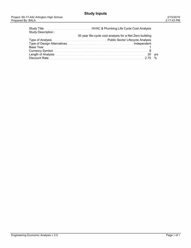
Study InputsProject: 60-17-442 Arlington High School 2/15/2019Prepared By: BALA 2:17:43 PM
Study Title HVAC & Plumbing Life Cycle Cost Analysis
Study Description :30 year life-cycle cost analysis for a Net Zero building
Type of Analysis Public Sector Lifecycle Analysis
Type of Design Alternatives Independent
Base Year 1
Currency Symbol $
Length of Analysis 30 yrs Discount Rate 2.75 %
Engineering Economic Analysis v 3.0 Page 1 of 1
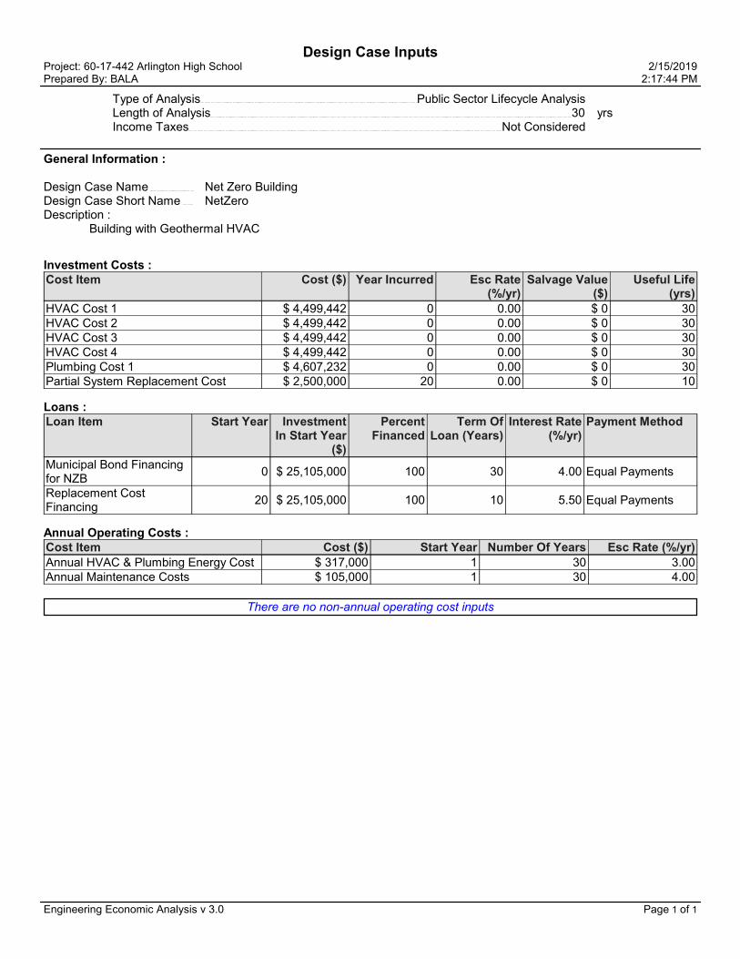
Design Case InputsProject: 60-17-442 Arlington High School 2/15/2019Prepared By: BALA 2:17:44 PM
Type of Analysis Public Sector Lifecycle Analysis
Length of Analysis 30 yrs Income Taxes Not Considered
General Information :
Design Case Name Net Zero BuildingDesign Case Short Name NetZeroDescription :
Building with Geothermal HVAC
Investment Costs :Cost Item Cost ($) Year Incurred Esc Rate
(%/yr)Salvage Value
($)Useful Life
(yrs)
HVAC Cost 1 $ 4,499,442 0 0.00 $ 0 30HVAC Cost 2 $ 4,499,442 0 0.00 $ 0 30HVAC Cost 3 $ 4,499,442 0 0.00 $ 0 30HVAC Cost 4 $ 4,499,442 0 0.00 $ 0 30Plumbing Cost 1 $ 4,607,232 0 0.00 $ 0 30Partial System Replacement Cost $ 2,500,000 20 0.00 $ 0 10
Loans :Loan Item Start Year Investment
In Start Year ($)
Percent Financed
Term Of Loan (Years)
Interest Rate (%/yr)
Payment Method
Municipal Bond Financing for NZB
0 $ 25,105,000 100 30 4.00 Equal Payments
Replacement Cost Financing
20 $ 25,105,000 100 10 5.50 Equal Payments
Annual Operating Costs :Cost Item Cost ($) Start Year Number Of Years Esc Rate (%/yr)
Annual HVAC & Plumbing Energy Cost $ 317,000 1 30 3.00Annual Maintenance Costs $ 105,000 1 30 4.00
There are no non-annual operating cost inputs
Engineering Economic Analysis v 3.0 Page 1 of 1


ELECTRICAL
260000 - 1
ARLINGTON HIGH SCHOOL
ELECTRICAL BUILDING SYSTEMS
SCHEMATIC DESIGN NARRATIVE
A. Demolition:
1. Project consists of phased demolition and phased construction. The new building construction is to be built in three phases from south to north with the existing building largely remaining in operation initially and then being phased out after the initial phase is complete. Demolition of the existing building will initiate after the first phase of new construction is complete. The electrical infrastructure and systems for the entire project will be constructed over all three phases.
2. Scope of Work
a. All work shall be constructed in compliance with the requirements of the 9th Edition of the Massachusetts Building Code/2015 International Building Code with amendments including the 2015 International Energy Code and the 2017 National Electrical Code with Massachusetts Amendments.
b. The building design will include features meeting the criteria for LEED for Schools Silver certification at a minimum.
c. All electrical systems shall be high-efficiency systems that allow for the ability towards achieving a Net Zero Energy facility.
d. Electrical systems shall be high-efficiency systems exceeding MSBA Sustainable Building Design Guidelines exceeding the level of energy efficiency required by the current MA Energy Code (ASHRAE 90.1-2013) by 20%.
e. New electric service from Eversource primary services.
f. Current existing utility primary service, transformation and secondary service to main switchboard including main switchboard will be maintained per phasing schedule.
g. New and existing panelboards feeders, mechanical equipment feeds, and branch circuits as required to maintain existing equipment per phasing schedule.
h. All required existing services shall be maintained for the complete operation of existing systems within existing school buildings to be maintained until the scheduled date of demolition of the existing building. Upon substantial completion, coordinate with the respective utility company and include all work required for the removal of all existing utility services including power, telephone, cable TV, and fire alarm services.
i. Phased demolition/construction enabling shall include:
1) New feeders from existing sources to maintain existing equipment to remain under respective phases.
Arlington High School Schematic Design Narrative February 20, 2019
ELECTRICAL
260000 - 2
2) Relocation and extension of existing feeders to maintain existing equipment to remain under respective phases.
3) Removal of existing equipment, feeders, and branch circuitry to be demolished remain under respective phases.
4) Existing fire alarm system shall be kept operational during phasing. Provide any additional equipment and wiring to maintain existing fire alarm system under respective phases.
B. Main Electric Service:
1. New primary services will be extended from utility company underground services via underground ductbank and manhole systems to new utility company pad mounted transformers.
2. Secondary service from the new pad mounted transformers by Eversource to the main switchboards at 480/277 volts, 3 phase, 4 wire.
3. Provide grounding of separately derived systems in accordance with Code Article 250.
C. Normal Distribution System:
1. Main switchboard will be provided with surge protection (SPD) and ground fault protection on main and feeder devices.
2. Each circuit breaker, 1,200 amp frame and above, shall include as part of the trip unit, Arc Flash Reduction Maintenance Technology, which shall reduce the trip system instantaneous pickup value when activated. The Arc Flash Maintenance System shall allow the operator to enable a maintenance mode which enables a preset accelerated instantaneous override trip to reduce arc flash energy. A blue LED on the trip unit shall indicate the trip unit is in the maintenance mode. The device must not compromise phase protection or defeat its functionality, even when enabled. Once disabled, the recalibration of phase protection must not be required.
3. Distribution system will consist of conduit and wire feeders run from switchboard to panelboards and larger mechanical equipment.
4. Panelboards and dry type transformers will be located in electric closets throughout the building. Transformers shall be CSL-3 premium efficiency.
5. Surge protection will be provided in all emergency panelboards and 120/208 volt receptacle panelboards.
6. Electric service will be provided to Toilet Facility Building
7. Space for inverters and conduits will be provided for PV systems.
D. Branch Wiring System:
1. Minimum size raceway shall be ¾ inch diameter and shall have no more than four (4) 90- degree bends in any one run, and where necessary, pull boxes shall be provided. Only rigid metal conduit or intermediate metal conduit is allowed for in-slab work. Cable systems, if allowed to be used by other sections of this specification, shall not be used exposed or in slabs, whether listed by "UL" for such use or not.

Arlington High School Schematic Design Narrative February 20, 2019
ELECTRICAL
260000 - 3
2. Rigid metal conduit may be used for service work, exterior work, slab work, and below grade level slab, wet locations, and in penthouse for drops down to equipment from elevations above eight feet and also where raceway may be subject to mechanical damage.
3. Electrical Metallic Tubing (EMT) may be used in masonry block walls, stud partitions, above furred ceilings, where exposed but not subject to mechanical damage and shall be used for fire alarm work.
4. Surface metal raceways shall be used where raceways cannot be run concealed. There shall be no surface mounted raceways without the acceptance of the Architect.
5. Flexible metal conduit shall be used for final connections to recessed lighting fixtures from above ceiling junction boxes and for final flexible connections to motors and other rotating or vibrating equipment. Liquid tight flexible metal conduit shall be used for the above connections which are located in moist locations. All flexible connections shall include an insulated grounding conductor.
6. Rigid non-metallic conduit may be used for underground electric and telephone services outside the foundation wall and shall be polyvinyl chloride (PVC) schedule 40, 90°C.
7. PVC Schedule 40 may also be used for below slab circuits within building confines and site lighting branch circuits. Below slab rigid non-metallic conduits do not require concrete encasement. Rigid non-metallic conduits shall not be used for exterior feeders, in slabs, nor for elbows which penetrate slabs. Raceways and fittings shall be produced by same manufacturer.
8. Acceptable manufacturers: Pittsburgh Standard Conduit Company, Republic Steel and Tube, Youngstown Sheet and Tube Company, Carlon, or equal.
9. Outlets, Pull, and Junction Boxes – Outlets: Each outlet in wiring or raceway systems shall be provided with an outlet box to suit conditions encountered. Boxes installed in normally wet locations or surface mounted shall be of the cast metal type having hubs. Concealed boxes shall be cadmium plated or zinc coated sheet metal type. Old work boxes with Madison clamps not allowed in new construction. Thru the wall boxes are not permitted.
10. Acceptable manufacturers: Appleton, Crouse Hinds, Steel City, RACO, or equal
11. Pull and Junction Boxes – Provide where necessary to terminate, tap off, or redirect multiple raceway runs or to facilitate conductor installation, provide appropriately designed boxes. Boxes shall be fabricated from code gauge steel assembled with corrosion resistant machine screws. Box size shall be as required by Code. Acceptable Manufacturers: Brasch, Hoffman, Keystone, Lee Products Co., McKinstry Inc., Eldon Inc., or equal.
E. Wiring Devices:
1. Receptacles shall be 20A and tamper proof.
2. Receptacles in wet locations shall be GFCI type.
3. All energy-controlled receptacles shall be labeled.
4. All standard 20 ampere devices to be of same manufacturer.
Arlington High School Schematic Design Narrative February 20, 2019
ELECTRICAL
260000 - 4
5. Acceptable manufacturers are Arrow Hart, Hubbell, or Leviton.
6. Composition material of wiring devices to be nylon.
7. Cover plates: Stainless Steel
a. Provide weatherproof “while-in-use” covers gaskets on all exterior receptacles.
F. Emergency Distribution System:
1. An exterior, ground mounted, 1500kW 277/480V diesel emergency generator with self-contained sound attenuated weatherproof enclosure will power the following:
a. Emergency/Life Safety: egress lighting and exit lighting in corridors, assembly areas, toilets, stairwells and fire alarm system.
b. Optional Standby: Kitchen walk-in coolers and freezers, kitchen equipment, kitchen ventilation system, telephone system, security system, IT MDF room and head-end, IT IDF rooms, IT IDF and MDF room cooling, chiller heaters, geothermal pumps, hot water circulator pump and controls, roof top units, additional lighting and receptacles in Pre-K area, School Department IT equipment and cooling, School Administration Offices, School Superintendent/District Administration Offices, School Nurse Areas in High School and LABBB, Gymnasiums, Locker Rooms, Rest Rooms, Kitchen and Cafeteria additional lighting, equipment and receptacles.
c. Fire Pump service
d. Legally Required Emergency: Stair pressurization fans, and one elevator.
2. Automatic Transfer Switches: Provide automatic transfer switches for operation on 277/480 volts, 3 phase, 4 wire operation, housed in NEMA 1 enclosures. Transfer switches shall be rated for minimum 42,000 arms. Entire switch shall be listed under UL 1008. Acceptable Manufacturers: Russ Electric RMTD (4 Pole), ASCO (with overlapping neutral contacts), Onan, or Kohler.
3. Provide a portable generator or hook-up connection to meet National Electric Code Article 700 requirements to have a portable generator available while servicing the building generator.
4. Provide a 400kW portable generator with hook-up connection to have a portable generator available for construction phasing.
G. Lighting:
1. Luminaires will be light emitting diode (LED) with high efficiency drivers, with 0-10V dimming protocol. All luminaires will be suitable for respective utility rebate incentives.
2. Selected luminaires in corridors, interior rooms, stairs, and places of assembly will be wired to emergency generator to provide minimum code required light levels.
3. Illuminated LED type exit signs will be wired to emergency generator and located in all paths of egress and places of assembly.

Arlington High School Schematic Design Narrative February 20, 2019
ELECTRICAL
260000 - 5
4. Outdoor lighting building mounted, roadway, walkway, and parking luminaires will be full cutoff LED type. All exterior lighting will be tied into the building low voltage lighting control system via wireless control system.
H. Lighting Controls:
1. Vacancy/occupancy sensors will control lighting in the majority of spaces including classrooms, offices, and utility type spaces.
2. A networked low voltage lighting control system will be provided for all areas such as corridors Gymnasiums, Cafeteria, Media Center, Stairwells, incorporation data collection vacancy/occupancy sensors and daylight harvesting. Local low voltage override switches will be provided for locations with time schedule functions.
3. Daylight harvesting will be employed in Classrooms, Gymnasiums, Cafeteria, Media Center, Stairwells, Offices, and other spaces with substantial day lighting.
I. Auditorium:
1. A professional theatrical lighting system will be provided including complete dimming system with portable dimming controls. Power and control wiring will be provided for all Auditorium and Stage equipment including electric winches, projection screens, and lifts.
J. Black Box Theater:
1. A professional theatrical lighting system will be provided including complete dimming system with portable dimming controls. Power and control wiring will be provided for all Black Box equipment including electric winches, projection screens, and lifts.
K. LEED v4:
1. USGBC LEED version 4 compliance will be provided.
L. Convenience Power:
1. Duplex receptacles will be provided throughout the building in quantities to suit space programming.
2. Duplex receptacles will be split wired and controlled via occupancy sensors in offices, computer labs and open office furniture systems to reduce plug loads by 50 percent to comply with applicable energy codes.
M. High Rise Fire Alarm System:
1. An automatic, fully supervised, addressable, voice evacuation system consistent with a high-rise building will be provided. Control panel will be located in located in Fire Command Center.
2. Audible/visual units throughout the building to meet code.
3. Visual only units in conference rooms, meeting rooms, and small toilets.
4. Smoke detector coverage will be provided in corridors, stairwells, Electric Rooms and Closets, Telephone/IT Rooms and closets, and rooms with substantial computer equipment

Arlington High School Schematic Design Narrative February 20, 2019
ELECTRICAL
260000 - 6
5. Duct smoke detectors in HVAC units over 2,000 CFM, and within 5 feet of smoke dampers.
6. Connections to sprinkler water flow, tamper switches, smoke and fire dampers, and Kitchen hood.
7. Smoke Control Systems Control Panel located in Fire Command Center.
8. Stair Pressurization System Control Panel located in Fire Command Center.
9. Area of Rescue Assistance stations throughout the building including stairwells and elevator lobbies to meet code. Control panel and annunciator shall be located in Fire Command Center.
10. Elevator Status Panel with fire service controls located in Fire Command Center.
11. Stairway Door operation controls located in Fire Command Center.
12. Leased phone line connection to UL Central Station will be provided.
13. Knox boxes and exterior beacons will be provided at Main Entry on Field side, entry at Massachusetts Avenue and entry District Offices.
N. Bi-Directional Antenna Systems
1. Bi-directional antenna systems will be provided to serve Arlington Fire Department radios
2. Bi-directional antenna systems will be provided to serve Arlington Police Department radios.
3. Equipment will be located in dedicated 2-hour fire rated spaces.
O. Sustainability Systems:
1. Provide Level 2 electric vehicle supply equipment (EVSE), charging stations, CSL 3 240V transformers with process load control and associated feeders and wiring in at least 10% of onsite parking spaces.
2. Provide space allocations and raceway infrastructure to accommodate Level 2 electric vehicle supply equipment (EVSE), charging stations, CSL 3 240V transformers with process load controls for 100% of onsite parking spaces in the future (“make ready”)
3. Provide space allocations and underground conduit system infrastructure for ground mounted PV (photovoltaic) equipment in all parking lots, covered bicycle parking, canopy over home bleachers, converted “away” bleachers on north side of turf field, and embankment between Minuteman bikeway and Peirce Field
4. Provide all electrical panels, equipment, space allocations and feeders to relocate existing roof mounted PV (photovoltaic) equipment to new locations in all phased construction.
5. Provide all electrical panels, equipment, space allocations and feeders for all new roof mounted PV (photovoltaic) equipment in new locations.
6. Provide automatic plug load control through low voltage control systems for a minimum of 50% of all receptacles in offices, workstation furniture, conference rooms, print and copy rooms, break rooms and classrooms in compliance with ASHRAE 2013. Automatic

Arlington High School Schematic Design Narrative February 20, 2019
ELECTRICAL
260000 - 7
control for these areas would be achieved with vacancy/occupancy sensors, in both wired and wireless configurations.
7. Provide automatic process load control via programmed time schedule through low voltage control systems during unoccupied times for water coolers, vending machines, appliances, kitchens, kitchen equipment, science classrooms, theater/scene shop, maker spaces, large load equipment, such as kilns with programmed firing schedules
8. Provide automatic process load control via occupancy sensors and programmed time schedule during unoccupied times for copiers, select kitchen equipment, break room appliances, and specialty classrooms such as keyboarding.
P. Measurement and Verification Metering Systems:
1. Provide networked energy measurement and verification submetering system for all lighting, mechanical and receptacle panelboards to aggregate energy usage and cost allocation of all loads.
2. Large equipment loads such as pumps and roof top units shall have individual meters.
3. Energy measurement and verification submetering system shall be integrated with building management system for reporting purposes.
Q. Stadium Toilet Facility:
1. A 480/277V electric service will be provided.
2. Panelboards and transformer will be provided to serve lighting, mechanical, plumbing and equipment loads.
3. Fire Alarm service will be provided.
4. Intrusion alarm service will be provided.
R. Telephone/Cable TV Services:
1. An underground conduit system will be provided for each service.
S. Town of Arlington Fiber Optic Service:
1. An underground conduit system will be provided for service.
T. Technology will be provided per Technology Section.
U. Future Expansion:
1. Provisions will be made for future expansion of power with a 100A 277/480V 3ph. 4w. lighting panel, lighting control panel, 30kva dry type transformer and 120/208V 3ph.,4w. 100A 42 circuit main circuit breaker panel per floor.
2. Provisions will be made for future expansion of fire alarm with remote notification appliance power supply panel connected to fire alarm loop per floor.
V. Swing Space in Existing School:
1. Phase 1 First Floor Classrooms will be subdivided into temporary High School Administration, Nurse and Registrar spaces. Scope of work shall include new branch circuitry from expanded existing power sources, Existing fire alarm, communications, and data

Arlington High School Schematic Design Narrative February 20, 2019
ELECTRICAL
260000 - 8
services will be provided from existing sources with new equipment. Power for new and existing to remain mechanical and plumbing equipment will be served from existing and new power sources. Lighting system shall include reuse of existing and lighting controls with relocated and new lighting. Lighting controls shall meet current energy codes.
2. Phase 2 Second Floor LABBB Program will be subdivided into temporary Drama classroom and associated spaces. Scope of work shall include new branch circuitry from expanded existing power sources, Existing fire alarm, communications, and data services will be provided from existing sources with new equipment as required. Power for new and existing to remain mechanical and plumbing equipment will be served from existing and new
power sources, including new split refrigerant air conditioning system. Lighting system shall include reuse of existing and lighting controls with relocated and new lighting. Lighting
controls shall meet current energy codes. Exterior spaces will be served with daylight dimming lighting controls.
3. Phase 2 Second Floor History Classrooms will be subdivided into temporary High School offices and conference room spaces. Scope of work shall include new branch circuitry from expanded existing power sources, Existing fire alarm, communications, and data services will be provided from existing sources with new equipment as required. Power for new and existing to remain mechanical and plumbing equipment will be served from existing
and new power sources, including new split refrigerant air conditioning system. Lighting system shall include reuse of existing and lighting controls with relocated and new lighting.
Lighting controls shall meet current energy codes. Exterior spaces will be served with daylight dimming lighting controls.
4. Phase 2 Second Floor Blue Gym will be temporarily repurposed for Cafeteria and kitchen services. Existing fire alarm, communications, and data services will be provided from existing sources with new equipment as required. Power for new and existing to remain mechanical and plumbing equipment will be served from existing and new power sources, including
kitchen equipment, kitchen hood exhaust fans and existing air handling units. New power distribution system shall be provided for kitchen. Lighting system shall include reuse of existing and lighting controls with relocated and new lighting and controls to meet current
energy codes. Exterior spaces will be served with daylight dimming lighting controls.
5. Phase 2 Third Floor Old Hall and Classrooms will be temporarily repurposed for Library Program Function Reach and Harbor programs. A temporary connection to Phase 1 buildings shall also be provided on floors 3 and 5. Scope of work shall include new branch circuitry from expanded existing power sources, Existing fire alarm, communications, and data services will be provided from existing sources with new equipment as required. Power for new and existing to remain mechanical and plumbing equipment will be served from existing and new power sources. Lighting system shall include reuse of existing and lighting controls
with relocated and new lighting and controls to meet current energy codes. Exterior spaces will be served with daylight dimming lighting controls.
6. Phase 3 First Floor Shower Bank will be subdivided into temporary Locker Rooms. Scope of work shall include demolition of existing locker room and new branch circuitry from expanded existing power sources, Existing fire alarm, communications, and data services will be provided from existing sources with new equipment as required. Power for new and existing to remain mechanical and plumbing equipment will be served from existing and new power sources. Lighting system shall include reuse of existing and lighting controls
with relocated and new lighting and controls to meet current energy codes. Exterior spaces will be served with daylight dimming lighting controls.
7. Phase 3 Temporary Walkway to connect Red Gym and Downs House will be provided. Scope of work shall include new branch circuitry from expanded existing power sources, Existing fire alarm, communications, and data services will be provided from existing sources

Arlington High School Schematic Design Narrative February 20, 2019
ELECTRICAL
260000 - 9
with new equipment as required. Power for new and existing to remain mechanical and plumbing equipment will be served from existing and new power sources. Lighting system shall include reuse of existing and lighting controls with relocated and new lighting and controls to meet current energy codes.
W. Testing:
1. Independent testing company will provide acceptance testing of work of this Section.
H:\60-17-442\ADMIN - Arlington High School\ADDENDUMS-BULLETINS-NARRATIVES\17-442-001-Elec SD Narrative.docx


Arlington High School
Audiovisual and Theatrical Systems Report
January 20, 2019
Auditorium
GeneralA. This proscenium theater will function as the main performance and presentation space for drama, musical theater, music performance, lectures and video presentations. It will function as a performance space and as an easy-to-use presentation space.
Audiovisual SystemA. Equipment
- Wireless microphones- Automatic microphone mixer- Digital mixing console- Digital signal processor- CD/media player- Permanent loudspeakers- Portable loudspeakers- Backstage audio monitoring and paging- Audio recording system, simple- Production intercom system- Digital audio network for communication within space and between space and Production
Studio- Roll-down projection screen in proscenium- Video inputs at stage and booth- Audiovisual switcher- Video projector- Touch panel control system- Video, audio and category tie line systems- Pan/tilt/zoom cameras

Arlington High School Page 2Audiovisual and Theatrical Systems Schematic DesignJanuary 20, 2019
Theatrical LightingA. Equipment
- LED lighting system- Motorized circuit breaker panel- Ethernet-based control system- Architectural lighting control- Switched power distribution- Wireless remote control for console- Company switch- LED lighting fixtures
Theatrical Rigging SystemA. Equipment
- Counterweight rigging system with pipes 9 to 12 inches on center- Stage curtains- Cyclorama- Scrim- Flown folding acoustic ceiling panels
Theatrical PlatformsA. Equipment
- Custom stage extension platforms
Black Box Theater
GeneralA. This is a flexible performance space for classes, plays and other theatrical presentations. It is designed to be a re-configurable space, allowing the user to experiment with the relationship of audience and performer.
Audiovisual SystemA. Equipment
- Wireless microphones- Digital mixing console- Digital signal processor- CD/media player- Effects playback computer and software- Portable loudspeakers- Backstage audio monitoring and paging- Production intercom system- Digital audio network- Video, audio and category tie line systems- Pan/tilt/zoom camera

Arlington High School Page 3Audiovisual and Theatrical Systems Schematic DesignJanuary 20, 2019
Theatrical LightingA. Equipment
- LED lighting system- Motorized circuit breaker panel- Ethernet-based control system- Architectural lighting control- Switched power distribution- Wireless remote control for console- LED lighting fixtures
Theatrical Rigging SystemA. Equipment
- Pipe grid over performance space- Masking drapery
Theatrical Platforms and SeatingA. Equipment
- Portable platform, step and railing system- Portable audience seating, stacking (under FF&E)
Cafeteria/Dining
GeneralA. Main dining space design to also serve as a gathering and presentation space when not in use as a cafeteria.
Audiovisual SystemA. Equipment
- Wireless microphones- Automatic microphone mixer- Digital signal processor- CD/media player- Permanent loudspeakers- Digital audio network- Roll-down projection screen- Video inputs at presentation locations- Audiovisual switcher- Bluray player- Video projector- Touch panel control system

Arlington High School Page 4Audiovisual and Theatrical Systems Schematic DesignJanuary 20, 2019
Band and Chorus Classrooms
GeneralA. Music classrooms with audio playback/recording systems for use with classes and rehearsals.
Audio SystemA. Audio recording and program playback system to support music classes and rehearsals.B. Equipment
- Recording microphone- Digital mixer with solid-state recording- Digital audio connections to other spaces via network- CD/media playback- Permanent stereo loudspeakers- Small equipment rack at teaching location in front of room- Audio input from classroom video presentation system
Production Lab & Studio
Audio SystemA. Audio recording system with network connections to venues in school for remote recording and broadcast.B. Equipment
- Digital mixing console- Permanent loudspeakers- Wiring infrastructure/connector panels from studio to control room
Video SystemA. Video production system with local and network connection to venues in school for remote recording and broadcast.B. Equipment
- Network-enabled video switcher/streamer- Pan/tilt/zoom cameras
Gymnasium
Audio SystemA. Audio program playback and voice reinforcement systems for sporting events, gym classes, recreational and event usage.B. Equipment
- Portable equipment cart for announcer table- Wireless microphones- Microphone mixer- Digital signal processor- CD/media player- Permanent overhead loudspeakers

Arlington High School Page 5Audiovisual and Theatrical Systems Schematic DesignJanuary 20, 2019
- Digital audio network- Media player and Bluetooth inputs- Volume control on wall- Motorized projection screen
Alternate P.E. – Fitness
Audio SystemA. Audio program playback for classes and recreational uses.B. Equipment
- Digital signal processor- Media player and Bluetooth inputs- Permanent overhead loudspeakers- Volume control
Alternate P.E. (2 rooms)
Audio SystemA. Audio program playback for classes and recreational uses.B. Equipment
- Digital signal processor- Media player and Bluetooth inputs- Permanent overhead loudspeakers- Volume control
Debate & Discourse Lab
GeneralA. Presentation and debate venue with thrust-style audience seating. Designed to be used as a content source space for broadcast and/or recording.
Audiovisual SystemA. Equipment
- Wireless and wired microphones- Automatic microphone mixer- Digital signal processor- Permanent loudspeakers- Digital audio network- Roll-down projection screen- Video inputs at presentation locations- Audiovisual switcher- Bluray player- Video projector- Touch panel control system- Remote-control pan/tilt/zoom cameras
Arlington High School Page 6Audiovisual and Theatrical Systems Schematic DesignJanuary 20, 2019
Amphitheater
GeneralA. This is an outdoor entertainment space for dramatic presentations, movies, music events and presentations.
Audiovisual SystemA. Equipment
- Permanent loudspeakers, amplifiers and processing- Use portable equipment from other spaces for audio input side- Use portable video projector
Theatrical LightingA. Equipment
- LED lighting system- Motorized circuit breaker panel- Ethernet-based control system- Switched power distribution- LED lighting fixtures to be integrated into architectural positions over the stage and on sides of
building wings

Arlington High School Page 7Audiovisual and Theatrical Systems Schematic DesignJanuary 20, 2019
Opinion of Probable Cost
Audiovisual Systems & Projection Screens $ 718,000 Auditorium $ 265,000 Black Box $ 65,000 Cafeteria $ 90,000 Chorus Room $ 14,000 Band Room $ 14,000 Production Lab $ 55,000 Gymnasium $ 70,000 Alternate P.E. - Fitness $ 20,000 Alternate P.E. (2) $ 30,000 Debate & Discourse Lab $ 60,000 Amphitheater $ 35,000
Theatrical Lighting Systems & Fixtures $ 385,000 Main Theater $ 235,000 Black Box $ 105,000 Amphitheater $ 45,000
Theatrical Equipment $ 422,500 Auditorium Rigging $ 260,000 Auditorium Platforms $ 32,500 Auditorium Orchestra Ceiling Panels $ 30,000 Black Box Theater $ 45,000 Black Box, Platforms $ 55,000
Total $ 1,525,500
Arlington High School Page 8Audiovisual and Theatrical Systems Schematic DesignJanuary 20, 2019
Notes on Opinion of Probable Cost
GeneralA. Figures above include a 10% design contingency.
Audiovisual SystemsA. Probable costs are estimated as the audiovisual contractor cost. It includes supply and installation of audiovisual equipment, low-voltage wiring and system programming. The estimate assumes the audiovisual contractor is installing cable into conduit provided under the electrical contract and not included in this estimate.B. Estimate includes audiovisual contractor system programming, commissioning and user training.
Lighting SystemsA. Probable costs are estimated as the theatrical lighting contractor cost. It includes supply of equipment by the theatrical lighting contractor to the electrical contractor for installation by the electrical contractor. Estimate does not include electrical accommodation or installation.B. Backstage work and running/blue lights not included in estimate. C. Estimate includes theatrical lighting contractor system commissioning and user training.
Rigging SystemsA. Probable costs are estimate as the theatrical rigging contractor cost. It includes the supply of equipment and physical installation by the theatrical rigging contractor. It does not include structural accommodation or electrical work.
17266/17266 AHS AV TL TR SD Narrative

Arlington High School / JN 29233
Job No. 29233.00 – January 11, 2019 Page | 1
TECHNOLOGY, AV, AND SECURITY SYSTEMS NARRATIVE
This narrative describes the information technology, AV, and security systems that will be incorporated into the project.
INTRODUCTION
The technology systems for the Arlington High School project include information technology, network, security, audiovisual, and educational technology systems. This document describes the major components of each of these systems and the anticipated configuration within the project. The emerging technology trends of consolidation and integration of the varying technology systems onto one integrated Internet Protocol network have informed the selection of technology systems and the anticipated style of integration within the project. The uniform and ubiquitously available network, wired and wireless, will be integrated throughout the project and leveraged as the single communications resource for connecting the varied systems and devices. This approach allows Arlington to leverage emerging technologies and technology market efficiencies, implementing a modern and sustainable electronic environment to support operations in educations within the facility. The network will be logically configured to support building-specific connectivity for the building systems including security, AV, building management, and similar communications requirements. The network will also be configured to support the administrative, educational, and wide-area connectivity. The network integration will be configured by the integrator, working with the IT department.
INFORMATION TECHNOLOGY AND STRUCTURED CABLING SYSTEM
Communications Carrier Connections and Services
The project will provide new diverse communications carrier connections to the school for enhanced Internet access capacity and operational redundancy. The redundant carrier connection to the building will come from the Massachusetts Avenue and the Summer Street sides of the campus. The specific capacity of the Internet connections will be identified as the time of installation approaches.
Television Service to the School and Distribution within the School
The local cable company, RCN, will provide traditional cable television services to the Main distribution frame room. Television programming is currently available on numerous non-cable company communication services including YouTube, etc. The school will select and distributed television programming, over the network, as required from cable and Internet sources.
Voice Backbone
The new telephone system will be a Voice over Internet Protocol, (“VoIP”), system and will use the data backbone for voice transmission. No dedicated voice backbone will be required.
Data/Network Backbone
Data backbone cabling will consist of plenum rated multimode OM-4 and single mode OS-2 fiber optic cable. The data backbone will be installed from the Main distribution frame room to each of the IDF room

Arlington High School / JN 29233
Job No. 29233.00 – January 11, 2019 Page | 2
throughout the building. This fiber-optic backbone will support voice, data, video, and associated network traffic.
Video Backbone
Video will be delivered over the data network, as Internet Protocol, “IP”, video traffic. Therefore, the traditional coaxial CATV distribution backbone is not required. Copper cabling and/or fiber optic cabling will be installed to locations in key public areas such as the gym, cafeteria, media center, etc., to support camera connections for video origination. This video content will travel over the data network. Fiber optic cabling for video origination points will also be included in the public areas.
Technology Infrastructure Spaces
Dedicated technology spaces are required throughout the project to support the integration of modern networking and electronic systems. The town/school data center will be relocated to the new IT department location in the DPW complex. A main equipment room, MDF, will be required for the project. This room will be approximately 10 ft x 20 ft in size. The MDF will house the connections with the outside communications carriers, main network, equipment, and locally housed electronic resources including servers, storage, security access control, AV main equipment, etc. Intermediate distribution frame rooms, (“IDF rooms”), will be distributed throughout the school to serve as wiring hubs. These rooms will be located so that the length of data cable originating in each room does not exceed 300 feet. Network switches and similar equipment will be co-located within these rooms. The IDF rooms will be approximately 10 ft x 12 ft in size. The MDF and IDF rooms will require dedicated cooling and specific electrical receptacles. The IDF rooms will also house the security system access control panels, and related low voltage main equipment. Emergency power will be required to support the critical communication systems, ensuring operability during emergency situations and/or loss of commercial power.
Station Cabling System
Station cabling will be Category 6a plenum rated cabling. The cables will originate in the serving IDF room and be routed to the jack location, either a fixed jack or a wireless access point location. Termination patch panels and accessories will be compatible Category 6a equipment. A minimum of a twenty-year extended performance and application warranty will be required for the structured cabling system. In light of the ongoing technology trends toward mobility, collaboration, and ubiquitous network coverage, the majority of technology access within the project will be based on wireless networking. There will be locations where wired outlets are required. In these locations, hardwired data elements will be provided in the quantities and at the locations appropriate for the anticipated systems. Wired outlets will be provided for fixed work positions including administration, teacher work rooms, and similar spaces. Wired outlets will also be provided for equipment main location connections including elevator machine rooms, fire alarm control panel, security main equipment, etc. Program specific portions of the buildings such as maker spaces, will be treated to support intense wired and wireless connectivity. The approach toward such collaborative spaces is to equip them as technology black box theaters so that they are prepared with the infrastructure to support current, emerging, and

Arlington High School / JN 29233
Job No. 29233.00 – January 11, 2019 Page | 3
anticipated technologies and learning approaches. This will provide the cost-effective flexibility required for these spaces to remain relevant and useful.
Network Electronics
The common network electronics systems, including routers and switches, will be based on the then current standards and commercial offerings. The network electronics will be configured to provide minimum 1 Gb connectivity to each wired cable. 10Gb connectivity will be provided between the MDF room and the IDF rooms. The network will support the modern performance and security characteristics and solutions that are currently available. Separate virtual local area networks will be configured for different types of traffic, different security level requirements, and implemented in the accepted best practices manner.
Cellular Signal Enhancement System, (“DAS”)
The requirement for cellular signal enhancement system capabilities will be assessed during the detailed phases of the design. The type of building materials and the balance between renovation, in addition to construction, will impact the availability and quality of cell signal within the building. Given modern building materials and existing conditions, it is anticipated that a cell signal enhancement system will be required, particularly for the lower levels of the building. The cell signal enhancement system will be an important part of the overall operational and safety communications capabilities within the building. It will support and enhance the mass notification capability and ensure that faculty, staff, and security personnel are able to communicate via cell and/or text throughout the facility. The project should anticipate the inclusion of a DAS system.
Telephone System
The telephone system for the school will be a Voice over Internet Protocol, (“VoIP”), telephone system that runs over the school network infrastructure. The call processing equipment and telephone instruments will be procured through the project. The system will incorporate software licenses to allow software only phones, “soft phones”, to run on administrative computers and simplify the integration between network devices, voice mail, messaging systems, and the school network. The system will support sophisticated call handling system such as call queuing and automated call distribution. These capabilities combined with call generation features, reverse calling/notification, will support the operational and safety communication requirements of the school. Telephone instruments and/or capability will be provided in classrooms, other educational spaces, offices, conference rooms, staff and faculty spaces, and throughout the facility. The objective is to ensure that there is ready access to telephones as required in normal and in emergency operations at the school.
Public Address System
A one-way public-address system will be provided throughout the project. Speakers will be provided in each space. The system will be equipped with an interface to allow the telephone system to initiate announcements from any phone, with an authorized access code. The public-address system is for announcements and tone distribution only, it does not provide two-way communications, listening-in, or other types of communications. Classroom telephone sets are being provided for two-way voice communications with classrooms. Offices and conference rooms will have a volume control to allow adjustment of the speaker volume. The volume control will not allow the volume to be completely turned off.

Arlington High School / JN 29233
Job No. 29233.00 – January 11, 2019 Page | 4
Speakers will be programmed into paging zones with corridors and common areas grouped into single zones. Classrooms will operate as independent zones but will be programmed into larger zones, by grade, wing, or other appropriate designation. The public address system will extend into the day care and district office portions of the project.
Mass Notification System
A mass notification approach and solution will be integrated into the project. The system will leverage the telephone system, public address system, and the school network to provide multiple modalities of emergency notification. The public safety representatives for the school and town will be consulted during the design and integration of this system to enhance the coordination of notification and first responder plans. The mass notification system will be capable of communicating with the school community, parents, students, faculty, staff, and town safety personnel in flexible and easily modified manners. The system will be equipped to use traditional communication such as email and support texting, reverse 911, and similar capabilities. The specific implementation of the mass notification system will be determined through collaboration with the designated representatives of school management, public safety, and other parties identified it by the district. The district is implementing Inforce 911 application on computers and phones. This application will be in place at the high school.
Master Clock System
A master clock system will be provided with clocks in all classrooms, offices, common and group spaces. Clocks within the gymnasium will be larger and equipped with protective screens. The clock system will be equipped with GPS input and will automatically provide time correction and synchronization. The system will be centrally powered with simple power wiring going to each clock, connecting in series to multiple clocks. This approach avoids the cost of having traditional power receptacles at each clock location, and the operational complications of periodic battery replacement.
Raceway and Support Systems
The cable support for this project will vary with the existing conditions and architectural aspects of the project. Where possible, cable tray will be installed to support and maintain the cables. Where cable tray is not practical, J-hooks will be used at four-foot intervals for cable support. Electrical metallic tubing will be used to support cables as they pass through walls, floors, and in other appropriate locations.
Telecommunication Grounding System
A uniform telecommunications grounding and bonding system shall be provided in accordance with EIA/TIA-607, Grounding and Bonding Requirements for Telecommunications in Commercial Buildings. This system shall be designed in conjunction with the electrical power grounding system. The telecommunications grounding backbone shall consist of solid copper busbars and copper conductors interconnected with the building grounding system at the service entrance equipment. All Bonding conductors shall be #6 AWG copper conductors, green in color or marked appropriately, and installed in continuous lengths, or as otherwise required by the standards and project conditions.

Arlington High School / JN 29233
Job No. 29233.00 – January 11, 2019 Page | 5
The telecommunications ground busbars shall be a minimum of 1/4-inch thick, solid copper bar, electro tin plated, and insulated from their supports.
Computers, Printers, and Devices
The teacher and student computers and associated devices including printers, will be procured as close to project completion as possible. There is an ongoing device refresh program in place. The project will synchronize with the ongoing refresh program and will procure the devices as required at that time. These devices and systems will be funded in part through the furniture, fixtures, and equipment, (“FF&E”), phase of the project. Additionally, some portion of the computers and portable devices may be funded through annual IT department refresh funding allocations.
LIBRARY MEDIA, CLASSROOM TECHNOLOGY, AND AV SYSTEMS
The audiovisual systems and capabilities for the school will reflect the recent enhancements, interactive technologies and the trends toward real time and relevant display of information. In today’s highly collaborative and socially interactive world, the role of real-time, relevant, information has emerged as a key expectation and enhancement or public gathering areas. The audiovisual systems in the public areas of the school will be configured to dynamically refresh content that has been deemed relevant and appropriate for the schools while supporting interactivity with the school populations. These implementations will include data sources such as schedule, weather, locally generated programming, etc. The guiding design principles for these systems are that they will leverage economical commercial technologies, simplified modern connections and will minimize dedicated control systems, electronics, and proprietary programming. This approach will provide the most flexible systems with the minimum level of ancillary equipment, reducing the initial system cost and the ongoing operations and maintenance of the systems. The AV systems controls and content management will be network based, leveraging the capabilities of the school-wide network to control equipment and share information. The control system will have the capability to turn off projectors and monitors at specific times of day to manage use and associated power. Leveraging the network will maximize the value of educational content, making it available throughout the school without requiring specific physical resources such as CDs etc. Audio-Visual Systems are included in this project, for the following areas:
Lobbies and public areas
- Large interactive and engaging information displays will be incorporated in a coordinated manner in lobbies and public gathering areas. The purpose of these displays is to provide situationally and contextually relevant information in an engaging manner. These systems are intended to enhance the faculty and student experience, stimulating interaction and informing people throughout the day.
- The public area displays will be configured to support operationally relevant information, student work, display of school relevant events, athletics, drama, etc.
- additional capabilities will include the dynamic display of select social media material in a manner that enhances interaction and interest on the part of the students. Examples of this approach include a real-time photo wall that groups locally generated school pictures by common topics of interest.

Arlington High School / JN 29233
Job No. 29233.00 – January 11, 2019 Page | 6
- Public displays will be integrated into the mass notification system to allow them to be taken-over in emergency situations and serve as notification screens.
Gymnasium, Cafeteria, Media center (large areas of gathering)
- Audio systems for these spaces will support wired and wireless microphones. Inputs will be provided for portable devices including digital music players. The systems in these spaces will be connected to other AV systems to provide the required sharing of audio and video content. Microphones will be provided to support presentations, panel discussions, and mobile use throughout the spaces.
- Display and/or projection systems will be incorporated into these large spaces to provide visual display as required.
- Control systems will be provided to simplify the use of the AV systems.
- The products and materials will be durable and specifically designed for the anticipated uses and demands of these spaces.
- The gym audio system will include heavy duty speakers such as Community brand speakers that are specifically constructed for active areas and the potential for “ball-strikes” and similar events. The amplification system and accessories will be located in a secured cabinet near the gym, to minimize student access.
Classroom AV Technology: Classrooms will be equipped with the following educational AV capabilities:
- Large front-of-room displays. These displays will be selected based on the current reliable technologies available at the time of installation. The displays will be sized appropriately for room depth, visibility, and anticipated use.
- Dedicated sound systems: These sound systems will provide voice lift within the classroom either via a lanyard microphone or handheld microphone. These systems will also provide program audio enhancement, broadcasting the audio from whatever video or media sources are being displayed within the room. The classroom sound systems will be connected to the public address system and will automatically be shunted when public address announcements are made.
- Connection from computers and portable computing devices to the large monitor will be wireless. The trend for this type of conductivity is moving toward integrated capabilities within the monitor. If required, third-party wireless connection devices such as Chromecast, Apple TV, or similar devices will be integrated as required.
- Note: Conference rooms within the school will be equipped with similar technologies and capabilities, scaled to the size and use of the specific spaces.
Arlington Community Media Studio will remain connected to the high school and this connection will be integrated into the AV production related assets and spaces within the high school. The nature and configuration of the connection and capabilities will be confirmed during the detailed design of the project.
Assistive Listening Systems
- Assistive listening systems will be provided in spaces identified by the relevant codes, including the gymnasium and cafeteria, and other areas as required. The system will be based on wireless technology, supported by the main audio system equipment.
Code and Operational Considerations

Arlington High School / JN 29233
Job No. 29233.00 – January 11, 2019 Page | 7
- Dedicated AV systems will be equipped with Fire Alarm system connections to shunt the local audio systems in the event of an alarm.
- Dedicated AV systems will be equipped with connections and controls to integrate them into the mass notification solutions/systems, thereby ensuring that they operate in a coordinated manner in case of an emergency.
B. Language Lab functionality will be provided by a Robotel, or similar, cloud-based language lab solution. The solution will be configured to support a minimum of 250 student licenses and associated teacher licenses. The complete suite of functionality including recording, pairing, advanced placement, (“AP”), testing and related functions are to be included.
SECURITY SYSTEMS
The security systems for the school will consist of access control, intrusion detection, surveillance, duress buttons and alarming. These systems will be designed and implemented in a coordinated manner that enhances the public safety and emergency management practices and policies of the district and town. The design of these systems will reflect the new reality of school security. One specific example of this approach is the dramatic reduction in active building openings. There will be a very limited number of doors which will be used for normal arrival and departure at the school. The remainder of building doors will be equipped with door position monitoring contacts. Existing Arlington Public School security system standards include:
• Surveillance cameras are Avigilon
• Access control readers are DSX
• Visitor management systems are Raptor. Design guidelines for active school entrances include:
• Surveillance cameras covering arriving and departing people
• Ballistic resistant treatments or glass are required for the entry vestibules
• Knox boxes are required for police and fire at both the front and rear main entrances
• Seniors will have the opportunity to scan in and out of campus, readers are to be provided in the vestibules at main entrances for this function
• Egress doors do not require hardware on the outside
• Interior surveillance is to be provided at all gathering areas or spaces that can support occupancies of 35 or greater and hallways, stairs, cafeteria, central building spine, media center, linking balcony, gym, weight room, black box theater, outside locker rooms and bathrooms, amphitheater
• Surveillance is required on the exterior portion of the campus to compliment the building exterior and interior coverage.
Access Control
The access control system will be coordinated with door hardware to ensure that designated doors within the building are programmable and operate in a manner consistent with the public safety program for the school. Building openings including doors, roof hatches, and other openings will be equipped with door position contacts.

Arlington High School / JN 29233
Job No. 29233.00 – January 11, 2019 Page | 8
Local door alarms will be incorporated into doors equipped with access control to alert management of unauthorized opening. Access Control main equipment panels will be located in the MDF and IDF rooms throughout the school. The access control system will be connected to the fire alarm system to allow overrides in the event of alarm conditions. The access control system shall provide real-time counts for entries and exits, with the calculated population at all times. This information shall be displayed at building entrance control points and within administration.
Door Intercom Systems
Door intercom systems, with signaling, audio and video connectivity are to be provided at the main entrance, supplementary entrances, and at the loading dock entrance. The systems will have one or more master control and viewing device located in the main office. The system will also have network connectivity to allow authorized users to view and control the systems from their computer and/or authorized network device, phone, etc. The door intercom system will be integrated into the access control system to allow selective unlocking etc.
Elevator Control/Access Systems
Elevator call/control capabilities will be provided through the access control system, using card readers at each elevator opening or within the car, and integration with the elevator control system. This will allow the school to restrict elevator use to authorized users through information related to their identification card, or other means. Elevator Lobby Emergency Communications Systems Elevator lobbies that do not have direct egress to grade will be equipped with two-way emergency communications systems that comply with the relevant code. These systems will be equipped with the tactile, audio, and video capabilities to allow emergency calls to be initiated and routed to permanently manned safety response positions. Calls originated from these stations will be routed over the school communications network to the answering positions. The systems are programmable and may be coordinated with existing or new answering positions in the future.
Intrusion Detection
Detectors will be located within the lobbies, main corridors, and within specialty spaces that house equipment of recognized value or are deemed appropriate for coverage. Motion detectors will be provided in corridors and stairwells to identify motion/presence. Motion detection will also be provided in large spaces such as the gymnasium, cafeteria, makerspaces, labs, or other rooms with valuable equipment. Glass break detection and/or motion detectors will not be provided in each classroom. The motion detection system will be configured into zones to allow the public use portions of the building to operate independently from the classroom areas. The zoning will be coordinated with the Owner and Architect. Alarm system key pads will be located inside strategic building entrances to allow selective disarming/arming of the zones. The main building wings are to be equipped in a manner that allows them to operate as separate zones and to be secured while activities may occur in other portions of the school.

Arlington High School / JN 29233
Job No. 29233.00 – January 11, 2019 Page | 9
Surveillance, CCTV, Recording and Monitoring
Exterior CCTV coverage will be provided around the entire perimeter of the school. Enhanced coverage will be provided at active building entrances. Camera resolution will be sufficient for facial recognition at and/or near the main entrances. Cameras will be provided with infrared illuminators for viewing and recording in low light conditions. Cameras will capture people as they enter and exit the building. Surveillance coverage will be provided in stairwells, corridors, and at other locations where incidents and/or issues may occur, as indicated in the design guidelines. Parking lot coverage will be provided at entrances and exits as well as for the portions of the parking lot visible from the building mounted CCTV cameras. License plate recognition and/or capture are not included in the systems for this project.
Indoor cameras will be dome ceiling and/or wall mount cameras. Exterior cameras will be provided with appropriate housings and mounted on the building and/or on adjacent lighting poles. Cameras will be digital multi-megapixel and the system will support digital zoom. Digital video recording and storage capabilities will be provided as part of the surveillance system. Initial system design will be configured to provide a minimum of one month of recorded data. This capacity estimate will be based on the use of “record on motion” and other current video management techniques. The video recording system will be accessible to authorized network users, within the building and/or to authorized personnel with network access.
Duress Buttons
Duress buttons will be provided at the main office reception desk, the principal and vice principal’s desks, guidance suites, and at strategic locations identified by the administration. Duress button activation will be automatically reported to the local police, through the alarm system. Mobile duress buttons will be required for a limited number of faculty and staff. Blue phone emergency call stations will be provided at locations identified by the district, school administration, and public safety personnel.
PHASING AND CONSTRUCTABILITY CONSIDERATIONS
The project will require communications and network continuity throughout the phased construction process. The IT department and town data center will be relocated to a new location within the adjoining DPW project area. There will be staffing space for the AHS specific IT personnel within the school. The new IT space will be connected to the town network. The high school construction phasing will require new redundant communications connections to the town network within the first phase of construction. The technology strategy is to construct the new communications entrances and facilities in the initial phase of the project while maintaining the existing network and communications capabilities in the remaining spaces. New communications backbone distribution will be provided to connect the remaining portions of the campus to the new network feeds and core. Temporary connections will be required from the first phase

Arlington High School / JN 29233
Job No. 29233.00 – January 11, 2019 Page | 10
of the project to the remaining IDF (wiring) rooms. As the project continues, permanent backbone cabling and IDF rooms will be provided in the new construction. The temporary backbone connections are to be implemented in a manner that minimizes additional temporary connections as the project continues. For example, the temporary backbone connections should be configured to maintain connectivity to the final remaining portions of the campus as the middle phases of construction occur. This approach will minimize the costs of temporary connections and additional phasing work. End of Section

Arlington High School Landscape Narrative
The presence and orientation of the new Arlington High School along Massachusetts Avenue is similar to its existing
condition. The school fronts on a slightly narrower (approximately 80’ typically) town green and includes an updated
and accessible school entrance that is flanked by two new school wings. The existing row of mature trees along the
back of sidewalk will be preserved and the redesigned greenspace will incorporate several new signature trees, multiple
ornamental trees, shrub and perennial plantings. Gracefully arching pathways connect the sidewalk with the main entry
from multiple points. Along these pathways will be benches for both the students and the community to enjoy, along
with the thoughtful siting of the existing memorials that are currently located within the school’s front lawn. Along the
eastern edge of the property a pathway doubles as a route for small vehicles to make material deliveries to the maker
spaces within the STEAM wing. At the schools main entrance, a wide, paved entry plaza serves as a gathering space as
well emphasizing the front of the school. Benches, a flagpole, special pavements and school signage will be located
within the plaza.
In addition to the new entry plaza along Massachusetts Avenue, there will be several other notable outdoor spaces
included within the proposed landscape. Located adjacent to and behind the STEAM wing will be a second gathering
space for students. Paved spaces adjacent to the classrooms serve as spaces where students can conduct their
coursework outside the building in a somewhat more private setting. A pattern of planted areas, raised planters and
paved areas create semi-private separation so that multiple groups can work independently in groups. A deck area with
platform seating allows for unstructured gathering opportunities or just to eat lunch. Located along Schouler Court and
between the Drama and Gymnasium building wings is an outdoor amphitheater room for hosting small performance or
movie events. An intimate space with rows of lawn panels separated with granite curbing, paved pathways to access the
stage area and special lighting will make this a desired space for a variety of events.
The parking and parent drop-off areas have been removed from close proximity to the main entrance, though there may
be opportunities for parent drop off and short term parking along Massachusetts Avenue. However, this area will take
precedence as a fire lane. Approximately 20 parking spaces will be provided along Schouler Court, adjacent to the
amphitheater and a short walk to the main entry of the school building. Continuing along Schouler Court and moving
clockwise around the back, one navigates down the slope in a switchback fashion as currently exists. Midway down the
slope is a large parking area (approximately 104 spaces) that will accommodate school visitors and staff, as well as
parking for visitors and athletes to the play fields during non-school hours. This parking lot also has potential to include
large PV panels that act as cover to the parked vehicles. The existing retaining wall that separates this area from the
baseball field below will be rebuilt to accommodate changes to the use of this area and the parking lot layout. A future
connection to Grove Street will also be accommodated within the layout design.
At the back of the school we are providing sidewalks, drop off areas and parking amenities. Two new sidewalks will
connect Mill Brook Drive through the school property to the DPW property / Grove Street to the west, as well as
connecting Schouler Court to the entrance at the back of the school. Along the south side of the drive is a nearly
continuous stretch of drop off / pick up space and along the north side of the drive are approximately 27 short term
parking spaces. Two small raised crosswalks will connect these parking areas to the rear of school plaza and one large
raised crossing will connect the rear entry of the school all the way through to W.A. Peirce Field. All three raised
crossings will serve to slow cars and create a safe area for students and cars to mix during the start and end of school.
Bollards will be incorporated at the raised crossing areas to protect pedestrians.
Between the student drop area and the rear entry of the school will be a large plaza space with tree, shrub, and
groundcover plantings. These planted areas will be interspersed with paths, benches and bollard lighting for students to
congregate while waiting for rides. A large paved area is located on the east side of the plaza that can be populated with
tables and chairs for seating during lunch or for special events.

Further along the loop drive, and at the easternmost side of the building we reach the Preschool wing with associated
drop off area. Adjacent to the preschool are two enclosed play areas, one for toddlers and one for slightly older
children. Both areas will have age appropriate structures and rubber safety surfacing. The entry to the Preschool is
access either by a ramp or set of stairs. Just to the south of the Preschool is the service entry for the school where
deliveries and trash disposal will take place. This area is screened from the preschool by a board fence and plantings,
but is accessed by a concrete sidewalk that leads to an area of covered bicycle parking.
The arc of the drive loop continues on and passes along a reconfigured parking lot (approximately 75 spaces) and a
revitalized landscaped edge to the Mill Brook. This new sidewalk edge along the Mill Brook completes the existing
sidewalk along Mill Brook Drive such that pedestrians can safely walk to the school from Mill Street.
Improvements to the playfield complex to the north of the school and loop drive are extensive. The reduction of the
building footprint and existing loop drive allows for the opportunity of a more connected and cohesive green space
within which the sports fields have been adjusted. On the west side of the sports area will be located a new regulation
sized softball field with associated fencing, and to the east side a new regulation sized baseball field with associated
fencing. Both of these fields will include artificial turf for year round play, as well as areas for practice fields. Between
these two fields will be a large area of open lawn area to be used for team practices or physical education. All field areas
will include new underdrainage and irrigation where applicable. Sports field area lighting will be updated further
extending the amount of time frame these fields can be used. The existing shot put area will be relocated adjacent to
the softball field, and the existing basketball courts will be removed. Lastly, a new restroom facility will be located in
proximity to the existing ticket booth associated with the W.A. Peirce Field.
Two major improvements to the connectivity of the Arlington High School and its surrounding community are also
proposed. The first is a 10’ wide elevated pedestrian and bikeway connecting the Minuteman Commuter Bikeway to a
small plaza space along the eastern most side of the property. This bikeway will thread itself between the outfield of the
baseball field and the Brigham Square Apartments property to its east and provide outstanding views back to the school
and sports complex. The elevated pathway will terminate in a small paved plaza with bike parking and a bicycle repair
station. The second circulation improvement is an 8’ wide elevated switchback pathway that connects Massachusetts
Avenue with the rear of the school along the east property line. This pathway would, for the first time, allow for people
to move around the entirety building and provide a second connection route from the front of the school to the back. A
staircase will also be provided in this area to make a connection, as well as plantings that create a buffer from CVS to the
east and to revitalize the slope.
CIVIL ENGINEERING NARRATIVE
Re: Arlington High School Expansion Samiotes Consultants File #17211.00 To: Lori Cowles - HMFH Architects From: Kevin Sanders – Samiotes Consultants, Inc. February 20, 2019 Stephen Garvin, PE – Samiotes Consultants, Inc. On January 22, 2018, Samiotes Consultants visited Arlington High School located at 869 Massachusetts Avenue, Arlington, Massachusetts to evaluate the existing site conditions. The following are preliminary civil findings and research of the existing infrastructure at the Arlington High School. This will be the basis of evaluating the potential for a new high school at the project site. Permitting & Further Site Investigations Permitting Requirements: Arlington Conservation Commission A Notice of Intent (NOI) will need to be filed for doing work within the commission’s jurisdictional area (within 100-feet of the wetlands and 200-feet from a river. It is assumed that the permitting process with conservation will take approximately 3-4 months. Hearings are held on the first and third Thursdays of every month. Applications must be submitted 10 days before hearing date. The Commission shall make a decision on the Notice of Intent based on information and material filed, the site visit and information presented at the meeting. If more information is needed, the meeting may be continued in compliance with applicable State and Town laws. The decision shall be issued within 21 days of the closing of the public hearing. The Town bylaw has certain buffer requirements that limit the work that can be done within each buffer. The Town has three types of buffer zones.
25’ “No Disturb” buffer: Within this zone no new work shall commence without the commission’s approval. The proposed project is proposing work within this buffer, however we will show to the commission that the work will improve the buffer condition from existing conditions and will improve drainage problems that exist today.
50’ “No New Structures” buffer: Within this zone no new building shall be erected without the commission’s approval. The proposed project is proposing work within this buffer, however we will show to the commission that the work will improve the buffer condition from existing conditions and will improve drainage problems that exist today.
100’ “Wetland” buffer: Within this zone the commission will review proposed work against the statutes of the Wetlands Protection Act and the Town Wetland Bylaw.
(14) Fourteen days prior to beginning construction, the project site operator will be required to develop a Stormwater Pollution Prevention Plan SWPPP and filing an ENOI with the EPA.
Samiotes Consultants, Inc. Civil Engineers + Land Surveyors 20 A Street Framingham, MA 01701-4102 T 508.877.6688 F 508.877.8349 www.samiotes.com

Page 2 SCI #17211.00 January 17, 2019 Arlington High School Civil Narrative Once a topographic survey is complete a FEMA flood boundary can be established from data received by FEMA. Any filling of land within this boundary will need to be offset by compensatory storage. We do not anticipate this being an issue. Arlington Redevelopment Board (Planning Board) The Town of Arlington’s “site plan approval” is under the special permit review under Environmental review. It is assumed that the review through the Redevelopment Board will take 3-4 months. The Hearings are held on the first and third Monday of each Month. The following will need to be addressed as part of the permitting:
Preservation of Landscape: The landscape shall be preserved in its natural state, insofar as practicable, by minimizing tree and soil removal, and any grade changes shall be in keeping with the general appearance of neighboring developed areas.
Relation of Building to Environment: Proposed development shall be related harmoniously to the terrain and to the use, scale, and architecture of existing buildings in the vicinity that have functional or visual relationship to the proposed buildings. The Arlington Redevelopment Board may require a modification in massing so as to reduce the effect of shadows on abutting property in an R0, R1 or R2 district or on public open space.
Open Space: All open space (landscaped and usable) shall be so designed as to add to the visual amenities of
the vicinity by maximizing its visibility for persons passing the site or overlooking it from nearby properties. The location and configuration of usable open space shall be so designed as to encourage social interaction, maximize its utility, and facilitate maintenance.
Circulation: With respect to vehicular, pedestrian and bicycle circulation, including entrances, ramps, walkways,
drives, and parking, special attention shall be given to location and number of access points to the public streets (especially in relation to existing traffic controls and mass transit facilities), width of interior drives and access points, general interior circulation, separation of pedestrian and vehicular traffic, access to community facilities, and arrangement of vehicle parking and bicycle parking areas, including bicycle parking spaces required by Section 8.13 that are safe and convenient and, insofar as practicable, do not detract from the use and enjoyment of proposed buildings and structures and the neighboring properties.
Surface Water Drainage: Special attention shall be given to proper site surface drainage so that removal of surface
waters will not adversely affect neighboring properties or the public storm drainage system. Available Best Management Practices for the site should be employed, and include site planning to minimize impervious surface and reduce clearing and re-grading. Best Management Practices may include erosion control and storm water treatment by means of swales, filters, plantings, roof gardens, native vegetation, and leaching catch basins. Storm water should be treated at least minimally on the development site; that which cannot be handled on site shall be removed from all roofs, canopies, paved and pooling areas and carried away in an underground drainage system. Surface water in all paved areas shall be collected at intervals so that it will not obstruct the flow of vehicular or pedestrian traffic, and will not create puddles in the paved areas.
Utility Service: Electric, telephone, cable TV and other such lines and equipment shall be underground. The
proposed method of sanitary sewage disposal and solid waste disposal from all buildings shall be indicated.
Advertising Features: The size, location, design, color, texture, lighting and materials of all permanent signs and outdoor advertising structures or features shall not detract from the use and enjoyment of proposed buildings and structures and the surrounding properties
Special features: Exposed storage areas, exposed machinery installations, service areas, truck loading areas, utility
buildings and structures, and similar accessory areas and structures shall be subject to such setbacks, screen

Page 3 SCI #17211.00 January 17, 2019 Arlington High School Civil Narrative
plantings or other screening methods as shall reasonably be required to prevent their being incongruous with the existing or contemplated environment and the surrounding properties.
Safety: With respect to personal safety, all open and enclosed spaces shall be designed to facilitate building
evacuation and maximize accessibility by fire, police, and other emergency personnel and equipment. Insofar as practicable, all exterior spaces and interior public and semi-public spaces shall be so designed as to minimize the fear and probability of personal harm or injury by increasing the potential surveillance by neighboring residents and passersby of any accident or attempted criminal act.
Heritage: With respect to Arlington's heritage, removal or disruption of historic, traditional or significant uses,
structures, or architectural elements shall be minimized insofar as practicable, whether these exist on the site or on adjacent properties.
Microclimate: With respect to the localized climatic characteristics of a given area, any development which
proposes new structures, new hard-surface ground coverage, or the installation of machinery which emits heat, vapor, or fumes, shall endeavor to minimize, insofar as practicable, any adverse impact on light, air, and water resources, or on noise and temperature levels of the immediate environment.
Sustainable building and site design: Projects are encouraged to incorporate best practices related to sustainable
sites, water efficiency, energy and atmosphere, materials and resources, and indoor environmental quality. Applicants must submit a current Green Building Council Leadership in Energy and Environmental Design (LEED) checklist, appropriate to the type of development, annotated with narrative description that indicates how the LEED performance objectives will be incorporated into the project.
Arlington Zoning Board: A special permit application may need to be filed with the Arlington Zoning Board of Appeals which meets on the second and fourth Tuesday of the month if the proposed building does not meet zoning requirements for the zone R1 district the school is located in. District Use Max Height (ft) Max Height (stories) Max floor area Ratio (FAR) R1 35 2.5 0.35 Further Site Investigation required: The following site investigations will be required to evaluate the site:
Wetland delineation and report. Traffic Investigation and report
The following survey will be required to evaluate the site:
Boundary & Topographic Survey Overview (Civil + Infrastructure) The existing major utilities review was based on site visit on January 22, 2018, reviewing plans of previous projects conducted on the site, and available GIS info. All major utilities (water, sewer, drainage, gas, & power) are available in vicinity of the existing campus. Currently the water, sanitary sewer, drainage, power and natural gas lines are available in the surrounding streets and drives, allowing for the potential of a new building to have access for connections.

Page 4 SCI #17211.00 January 17, 2019 Arlington High School Civil Narrative
Off-site Improvements As part of this project there will be proposed a new traffic signal along with timing sensors at the Mill Brook Drive and Mill Street intersection to help school traffic egress. Utility Phasing In efforts to construct the proposed high school expansion with minimal disruptions to the students and faculty as the existing high school will continue to be used, the utility disconnects, temporary routing, and new services must be phased and safeguards put in place to minimize relocations in later phases of the project. The below is our narrative of best management practices for the utilities to achieve that goal. Utilities Phase 1 Gas: Preliminary utility research shows an existing 4” gas line within Schouler Court that continues around the existing building to an existing gas meter at the rear of the building. There is also is a 4” line that tees off that line to the existing gas meter in front of the existing high school building. In Phase 1 (PH1) we propose to tap off this existing gas line with (2) two new gas lines.
The first of these gas lines would run (280 +/- LF) along the outside of the existing high school building, adjacent to Massachusetts Avenue, to the existing gas meter.
The second line would run (100 +/- LF) to the western side of the proposed PH1 building outside the auditorium to a new gas meter.
It is assumed that the existing gas line that loops around the north of the site between the existing high school building and playing fields would remain and be protected during this phase of construction. The MEP Engineer shall provide proposed loads to the gas company for adequacy and sizing. All gas meter and line work shall be to NGRID standards.
Water Service: Preliminary utility research shows (4) four water services for the existing high school that tap of the Massachusetts Avenue water mains along with (2) two 6” water mains that run up Schouler Court.
Several water lines will be abandoned, relocated or removed in Phase 1.
The two water mains that run up Schouler Court will remain intact and will be tied into to create new domestic and fire services to the new PH1 building.
A water line with an unknown size runs into the western side of the existing high school building. This line will be cut and capped at the main and abandoned in place.
A second 6” water line that services a hydrant in front of the existing high school building will be cut and
relocated around the east side of the existing high school building as shown on plans by Samiotes Consultants. The hydrant will be relocated or replaced as shown.
A third 2” water line will be cut and capped at the main and abandoned in place.
Page 5 SCI #17211.00 January 17, 2019 Arlington High School Civil Narrative
A fourth 8” water line will be cut and capped at the main and abandoned in place.
In Phase 1 (PH1) we propose to tap off this existing 6” water lines in Schouler Court with (3) three new services.
The first of these, a 4” domestic water line (63 +/- LF), will tee off the existing main and run to the western side of the proposed PH1 building.
The second line, a 6” fire service (63 +/- LF), will tee off the existing main and run to the western side of the proposed PH1 building.
The third line, a 4” domestic service (73 +/- LF), will tee off the existing main and run the western side of the
existing high school building.
In Phase 1 (PH1) we propose to tap off this existing 6” water line that comes from Massachusetts Avenue with a new 6” relocated service (552 +/- LF). There is also an auxiliary 6” water line (158 +/- LF) where the potential future addition is proposed.
Sanitary Sewer: Preliminary utility research shows a 6” sewer line running to the front of the existing building from a sewer main in Massachusetts Avenue. This line will be cut and a new sewer manhole will be added. There will be (2) two new sewer services from the PH1 building that exit the west and east sides of the building and will be routed around to connect to this manhole and (1) new temporary sewer service from the existing high school.
The first of these, a 6” SDR-35 PVC sewer line (17 +/- LF) will leave the west side of the PH1 building to a new sewer manhole. From this new sewer manhole a new 6” SDR-35 PVC sewer line (122 +/- LF) will run to a new sewer manhole. The final leg of this run will propose a new 6” SDR-35 PVC sewer line 6” SDR-35 PVC sewer line (280 +/- LF) to a new sewer manhole that connects to the existing sewer line.
The second of these, a 6” SDR-35 PVC sewer line (10 +/- LF) will leave the east side of the PH1 building to a new sewer manhole. From this new sewer manhole a new 6” SDR-35 PVC sewer line (87 +/- LF) to a science waste tank (see MEP for type/size) and will exit as a new 6” SDR-35 PVC sewer line (68 +/- LF) to a new sewer manhole that connects to the existing sewer line. The will also be an auxiliary 6” SDR-35 PVC sewer line (85 +/- LF) where the potential future addition is proposed.
A temporary 6” SDR-35 PVC sewer line (192 +/- LF) will run underneath the PH1 building to handle the existing high school building’s sewer.
Drainage: There is an existing 36” culvert that runs beneath the building. This culvert will be relocated as shown with 36” HDPE piping (640 +/- LF) and (6) six drain manholes shown on plans by Samiotes Consultants and routed to a below-grade stormwater management system that will help attenuate high flows before entering the Mill Brook culvert. There also will be an auxiliary 36” HDPE culvert pipe (640 +/- LF) with (3) three drain manholes where the future building addition may be proposed. The existing drainage structures and pipes not shown to be relocated shall be removed. Utility Routing: It is not anticipated that any of the PH1 utility work will affect the lined soil areas within the site. If the GC encounters any impacted soils they are to seek guidance from the project License Site Professionals (LSP’s) before continuance.

Page 6 SCI #17211.00 January 17, 2019 Arlington High School Civil Narrative Utilities Phase 2 Gas: Gas is not impacted or proposed in Phase 2. Water Service: In Phase 2 (PH2) a new 6” water service (400 +/- LF) is to be run to the loading dock limits from the existing water main as shown on plans by Samiotes Consultants. There also will be a new 6” water service (234 +/- LF) that will run to a new hydrant assembly. Sanitary Sewer: A new 6” SDR-35 PVC sewer line (75 +/- LF) will run from the edge of the proposed loading dock to a grease trap (see MEP for size/ type) and will continue as a 6” SDR-35 PVC sewer line (97 +/- LF) to a new sewer manhole and then will continue as a new 6” SDR-35 PVC sewer line (76 +/- LF) to a new “doghouse” manhole on the MWRA sewer line. Drainage: There are existing drainage structures and pipes to be removed. New drainage pipes (approximately 250 lf of 12” HDPE pipe) and structures (two catch basins and one manhole) are shown for Phase 2 parking improvements on the eastern edge of the site. These drainage pipes and structures will be routed into the new below-grade stormwater management system built in PH1. Utility Routing It is not anticipated that any of the PH2 utility work will affect the lined soil areas within the site. If the GC encounters any impacted soils they are to seek guidance from the project License Site Professionals (LSP’s) before continuance. Utilities Phase 3 Gas: The gas line that runs around the existing high school building will be cut/capped and abandoned in place after the proposed connection shown on Phase 1. There is no proposed gas lines proposed in Phase 3. Water Service: Water services are not impacted or proposed in Phase 3. Sanitary Sewer: Three new sanitary sewer services (approximately 602 lineal feet of SDR-35 PVC) that exit the rear of the new building will be routed through sewer manholes (seven sewer manholes) and conveyed to one of two new “doghouse” manholes on the MWRA sewer line. Drainage: The existing drainage line that runs from the DPW yard across the site will have to be relocated to a new line that runs behind the proposed building (approximately 70 lineal feet of 12”HDPE piping and 764 lineal feet of 18” HDPE piping). Two new catch basins and approximately 144 lineal feet of 12” HDPE piping will be added at the existing soccer fields that will connect to this new drainage line. This line will also pick up the roof drain pipes that will ultimately discharge into the Mill Brook culvert. Utility Routing It is not anticipated that any of the PH3 utility work will affect the lined soil areas within the site. If the GC encounters any impacted soils they are to seek guidance from the project License Site Professionals (LSP’s) before continuance.
Page 7 SCI #17211.00 January 17, 2019 Arlington High School Civil Narrative Utilities Phase 4 Gas: Gas is not impacted or proposed in Phase 4. Water Service: A new 4” domestic water service will be added to the new toilet building and run to the existing 6” water line (location to be determined). Sanitary Sewer: A new approximately 36 lineal foot 6” SDR-35 PVC sewer service will run from the new toilet building to a new “doghouse” manhole on the MWRA sewer line. Drainage: Two new catch basins and associated drain lines (approximately 164 lineal feet of 12” HDPE piping) will constructed in Phase 4. Utility Routing It is not anticipated that any of the PH4 utility work will affect the lined soil areas within the site. If the GC encounters any impacted soils they are to seek guidance from the project License Site Professionals (LSP’s) before continuance.
If you have any questions or comments regarding this narrative, please call or email [email protected] 508-877-6688 (ext. 32) or Stephen Garvin, PE at [email protected] (ext. 13).

Page 8 SCI #17211.00 January 17, 2019 Arlington High School Civil Narrative
Utility Specifications

WATER SYSTEM 331000 - 1
HMFH FEBRUARY 20, 2019
ARLINGTON HIGH SCHOOLARLINGTON, MA
SECTION 331000
WATER SYSTEM
PART 1 - GENERAL
1.1 DESCRIPTION OF WORK
A. Furnishing and installing utility lines, reducers, etc. beyond 10 (ten) feet from the foundation and connecting these lines that are included under the mechanical work.
1.2 REFERENCE STANDARDS
A. American National Standards Institute/American Water Works Association (ANSI/AWWA): C104/A21.4 Cement-Mortar Lining for Ductile-Iron and Gray-Iron Pipe and Fittings for
Water C110 Gray-Iron and Ductile-Iron Fittings, 3 in. through 48 in., for Water and
Other Liquids C111/A21.11 Rubber-Gasket Joints for Ductile-Iron and Gray-Iron Pressure Pipe and
Fittings C151/A21.51 Ductile-Iron Pipe, Centrifugally Cast in Metal Molds or Sand-Lined
Molds, for Water or other Liquids for Water or other Liquids C500 Gate Valves, 3 through 48 in. NPS, for Water and Sewage Systems C600 Installation of Ductile-Iron Water Mains and Their Appurtenances C601 Disinfecting Water Mains
B. Federal Specifications (Fed. Spec.) WW-T-799E Tube, Copper Seamless, Water (For use with Solder-Flared or Compression-Type Fittings).
C. American Society for Testing and Materials (ASTM):
A 120 Black and Hot-Dipped Zinc-Coated (Galvanized) Welded and Seamless Steel Pipe for Ordinary Uses
B 61 Steam or Valve Bronze Castings B 62 Composition Bronze or Metal Castings B 88 Seamless Copper Water Tube

WATER SYSTEM 331000 - 2
HMFH FEBRUARY 20, 2019
ARLINGTON HIGH SCHOOLARLINGTON, MA
PART 2 - PRODUCTS
2.1 DUCTILE IRON PIPE AND PIPE FITTINGS
A. Ductile iron (DI) pipe for water mains shall be designed in accordance with ANSI/AWWA C150/A21.50 and shall be manufactured in accordance with ANSI/AWWA C151/A21.51. Unless otherwise indicated or specified, ductile iron pipe shall be at least thickness Class 52. 1. DI pipe shall be push-on joint type. 2. DI fittings shall conform to ANSI/AWWA C110, and shall be of a-pressure
classification at least equal to that of the pipe with which they are used. 3. Gaskets shall conform to ANSI/AWWA Clll/A21.114 4. Inside of pipe and fittings shall be given a cement lining and bituminous seal coat in
accordance with ANSI/AWWA C104/A21.4. The outside of pipe and fittings shall be coated with a standard bituminous coating conforming to ANSI/AWWA C151/A21.51 and C110, respectively.
5. Pipe for use with sleeve-type couplings shall be as specified above except that the ends shall be plain (without bells or beads). The ends shall be cast or machined at right angles to the axis.
2.2 VALVE AND VALVE BOXES
A. Gate valve shall be iron body, bronze mounted, wedge valve, conforming to ANSI/AWWA C500. Gate valve shall be designed for a minimum working pressure of 250 lbs. per sq. in. and a minimum test pressure of 500 lbs. per sq. in. It shall be resilient seated and epoxy coated.
B. Tapping sleeve and valve shall consist of a split cast iron sleeve tee with mechanical joint ends on the main and a flange on the branch, and a tapping type gate valve with one flange and one mechanical joint end. Valve shall conform to the requirements specified above for gate valve. The Contractor shall be responsible for verifying the outside diameter of the pipe to be tapped. Valve shall have oversized seat to permit the use of full size cutters.
C. Tapping sleeve shall be Mueller H 615 (or equal approved by WWD) and gate valve shall be approved by the WWD and the Architect and be manufactured by one of the following:
Mueller Co., Decatur, IL or approved equal.
D. Each valve shall be provided with a valve box. Box shall be cast iron and shall be an adjustable telescoping, heavy pattern type. 1. Box shall be designed and constructed to prevent the direct transmission of traffic
loads to the piping or valve. 2. Upper section of box shall have a flange with sufficient bearing area to prevent undue
settlement. Lower section of box shall be designed to enclose the valve operating nut and stuffing box, and rest on the backfill.
3. Boxes shall be adjustable by 6 in. vertically without reduction of the lap between sections to less than 4 in.
4. Inside diameter of box shall be at least 4-1/2 in. and length of box shall be as required to suit finish ground elevation.
5. Box cover shall be close fitting and substantially airtight. Top of cover shall be flush with top of box rim. Cover shall have an arrow and the work "OPEN" cast into top to indicate direction of turning to open the valve.

WATER SYSTEM 331000 - 3
HMFH FEBRUARY 20, 2019
ARLINGTON HIGH SCHOOLARLINGTON, MA
6. Valve body and bonnet shall be of ductile iron coated on all exterior and interior surfaces with a Permafuse, or equal, fusion bonded epoxy conforming to AWWA Standard 550, latest revision, applied with a minimum thickness of eight (8) mils.
7. The gate shall be completely covered with rubber over all exterior ferrous surfaces. The rubber shall be securely bonded to the gate body. The valves shall be designed so that during operation, or cycling of the valve, there is no friction or abrasion or rubbing together that could wear away any coating material and expose bare iron. The interior of the valve body shall be free of pocket or ledges where sediments or debris can collect.
8. The “O” ring stem seal shall be replaceable with the valve under pressure in the full open position.
9. Valve shall be capable of operating through 1000 full cycle with zero leakage and without regard to direction of valve discharge or operating pressures, with no measurable wear on internal surfaces.
10. Resilient seated Tapping Valves shall be furnished with the tapping flange having a raised face or lip designed to engage the corresponding recess in the tapping sleeve flange in accordance with MSS SP60. The interior of the waterway in the body shall be full opening and capable of passing a full sized shell cutter.
11. All valves shall be manufactured in the United States.
2.3 EMBEDMENT MATERIALS
A. Ductile iron water pipe shall use materials defined in AWWA C 600, Sec. 3.5, Backfilling and shall confirm to massDOT Specifications M1.01.0.
B. Copper pipe embedment shall conform to MassDOT Specifications M1.04.0b.
2.4 HYDRANT
A. Hydrant shall conform to AWWA C502 and local governmental authorities having jurisdiction. Hydrant shall be positive automatic drain type to prevent freezing, and shall have one 4-1/2 in. pumper and two 2-1/2 in. hose connections. Main valve opening shall be 5-1/4 in. and valve shall open to meet Town of Arlington standard. Inlet connection shall be 6 in., mechanical joint.
B. Hydrant shall be approved by the Arlington Water Department and shall be manufactured by one of the following:
Mueller Co., Decatur, IL Kennedy Valve Mfg. Co., Elmira, NY American-Darling Valve, Birmingham, AL
C. Color of hydrant shall match Town of Arlington standard. END OF SECTION

SANITARY SEWAGE SYSTEM 333000 - 1
HMFH FEBRUARY 20, 2019
ARLINGTON HIGH SCHOOLARLINGTON, MA
SECTION 333000
SANITARY SEWAGE SYSTEM
PART 1 - GENERAL
1.1 DESCRIPTION OF WORK
A. Furnishing and installing utility lines, structures, etc. beyond 10 (ten) feet from the foundation and connecting these lines that are included under the mechanical work.
B. The Contractor shall pay for all costs and fees related to connecting sanitary sewage system to existing services and shall file all applications, details, and drawings required by the local authority having jurisdiction.
1.2 REFERENCED STANDARDS
A. American Association of State Highway and Transportation Officials (AASHTO Specifications: Standard Specifications for Highway and Bridges
B. American Society for Testing and Materials (ASTM): A 48 Gray Iron Casting. C 270 Mortar for Unit Masonry D 3034 Type PSM Poly (Vinyl Chloride) (PVC) Sewer Pipe and Fittings D 3212 Joints for Drain and Sewer Plastic Pipes Using Flexible Elastomeric Seals
C. Federal Specifications (Fed. Spec.): QQ-A-200/8 Aluminum Alloy Bar, Rod, Shapes, Tube and Wire, Extruded, 6061.
D. Cast Iron Pipe Institute (CISPI): 301 Hubless Cast Iron Sanitary System
E. Massachusetts Department of Transportation – Highway Division Standard Specifications for Highways and Bridges: massDOT – Highway Standard Specifications:
PART 2 - PRODUCTS
2.1 PVC PIPE AND FITTINGS (NONPRESSURE)
A. Polyvinyl chloride (PVC) nonpressure pipe for gravity sewers shall conform to ASTM D 3034, SDR 35 minimum wall thickness or ASTM D 1785 Schedule 40 when specified on the Drawings.
B. Pipe shall be bell-and-spigot type, furnished in standard lengths of 12'-6".

SANITARY SEWAGE SYSTEM 333000 - 2
HMFH FEBRUARY 20, 2019
ARLINGTON HIGH SCHOOLARLINGTON, MA
C. Bell end shall be an integral wall section with solid cross section rubber ring, factory assembled.
D. Spigot end shall be beveled to ensure proper insertion. Spigot end shall be imprinted with an "assembly stripe", to which the bell end of the mated pipe will extend upon proper jointing of the two pipes.
E. Rubber rings shall conform to ASTM D 3212.
F. Pipe ends shall permit checking of the rings with a feeler gauge to ensure their proper location in the coupling grooves.
G. PVC fittings shall be bell-and-spigot type compatible with the pipe.
2.2 MORTAR
A. Mortar shall conform to ASTM C 270, Type M.
B. Mortar shall contain a waterproofing admixture. Waterproofing admixture shall be one of the following:
Admixture Manufacturer Hydratite Plus W.R. Grace and Company Medusa Waterproofing Medusa Portland Cement Company Omicron Mortarproofing Master Builders Company Mortaron The Aquabar Company Hydrocide Powder Sonneborn Building Products, Inc.
or approved equal.
2.3 GROUT
A. Grout shall be nonshrink cement-based type equal to: Product Manufacturer Embecoa Builders Company, Cleveland, OH Five Star Grout U.S. Grout Corp., Old Greenwich, CT
Upcon 262 Upco Co., Cleveland, OH
2.4 SANITARY SEWER MANHOLES
A. Precast Units: 1. Structure: 48-inch diameter precast units (4,000 psi minimum compressive strength)
with eccentric cone section tapering to 24-inch diameter and one pour monolithic base section per ASTM C478.
2. Precast Unit Joint: Butyl rubber section joint per ASTM C443. 3. Steps: Steel reinforced copolymer polypropylene steps per ASTM C478, paragraph 11. 4. Exterior: Bituminous coating, 2 coats. 5. Manhole Frame and Cover: Grey iron casting per ASTM A48, heavy duty, with word
"Sewer" on cover. Letter size shall be two (2) inches. Frame and cover shall be Town of Arlington standard.
6. Pipe Connections: Flexible sleeve or rubber gaskets ("Lock Joint," Kor-n-Seal," "A-Lok"

SANITARY SEWAGE SYSTEM 333000 - 3
HMFH FEBRUARY 20, 2019
ARLINGTON HIGH SCHOOLARLINGTON, MA
or approved equal).
B. Manhole shall be similar to those be manufactured by: Concrete Systems, Inc., Hudson, NH. Chase Precast Corp., North Brookfield, MA Superior Concrete Co., Auburn. ME E.F. Shea New England Concrete Products., Wilmington, MA or approved equal.
2.5 SANITARY SEWER MANHOLES FRAME AND COVERS
A. Manhole frames and covers shall be cast iron conforming to the requirements of ASTM A48, Class 30, and shall be of noiseless, non-rocking design with pick holes. The word "Sewer" shall be cast on each cover in three inch letters as applicable. The castings shall be made in the United States.
B. Standard manhole covers and frames shall have a minimum total weight of 420 pounds with a clear opening of 26-inches, unless otherwise indicated on the Drawings. Standard manhole frames and covers shall be LeBaron Foundry Company (Model No. LK110) or equal as manufactured by Neenah Foundry Co., or Campbell Foundry Co.
C. Manufactured to withstand H20 loading.
2.6 PRECAST CONCRETE GREASE TRAP (INTERCEPTOR)
A. Precast concrete grease trap:
1. Precast concrete grease trap shall be designed for AASHTO HS-20 loading and have steel reinforcement in accordance with ASTM A-615-75 Grade 60, 1” Minimum Cover.
2. Tank shall have a concrete minimum strength of 5,000 P.S.I. @ 28 days. 3. Grease trap shall be constructed with tongue and groove joints between sections.
Joints between sections shall be sealed with preformed rubber gaskets conforming to ASTM C 443.
4. Exterior surfaces of grease trap shall receive a heavy shop-applied coating of bituminous waterproofing equal to: Product Manufacturer Super Service Black Koppers Company, Inc., Pittsburgh, PA No. 46-449 HD Black Themec Company, Inc., North Kansas, MO No. 35-J-10 Hi Built Mobile Chemical Company, Bituminous Coating Edison, NJ
5. Each section of the grease trap shall have no more than 2 suitable lifting holes or
cast-in lifting devices. 6. Precast grease trap shall be manufactured with wall openings to receive the ends of
pipes which are to be connected to structure. Pipe openings in base shall be minimum size required to receive pipe, and shall be accurately set to conform to the required line and grade.
B. Precast concrete grease trap shall be similar to those be manufactured by:
1. Rotundo Precast, Rehoboth, MA 2. Scituate Ray Precast, Scituate, MA
SANITARY SEWAGE SYSTEM 333000 - 4
HMFH FEBRUARY 20, 2019
ARLINGTON HIGH SCHOOLARLINGTON, MA
3. E.F. Shea New England Concrete Products., Wilmington, MA
2.7 EMBEDMENT MATERIALS
A. PVC pipe bedding and surround shall be Well-Graded Sand or Washed Dust
B. Backfill over the pipe bedding shall be clean fill. END OF SECTION

STORM DRAINAGE SYSTEM 334000 - 1
HMFH FEBRUARY 20, 2019
ARLINGTON HIGH SCHOOLARLINGTON, MA
SECTION 334000
STORM DRAINAGE SYSTEM
PART 1 - GENERAL
1.1 DESCRIPTION OF WORK
A. Furnishing and installing storm drainage lines, structures, etc. beyond 10 (ten) feet from the foundation and connecting these lines that are included under the mechanical work.
1.2 REFERENCE STANDARDS
A. American Association of State Highway and Transportation Officials (AASHTO):
B. American Concrete Pipe Association (ACPA):
C. Concrete Pipe Design Manual
D. American Society for Testing and Material (ASTM):
C 55 Concrete Building Brick C 62 Building Brick (Solid Masonry Units Made from Clay or Shale) C 140 Sampling and Testing Concrete Masonry Units C 270 Mortar for Unit Masonry C 443 Joints for Circular Concrete Sewer and Culvert Pipe, Using
Rubber Gaskets C 564 Rubber Gaskets for Cast Iron Soil Pipe and Fittings D 1557 Moisture-Density Relations of Soils and Soil Aggregate Mixtures
Using 10-lb. (4.5-kg) Rammer and 18-in. (457-mm) Drop D 2487 Soils for Engineering Purposes F 405 Heavy Duty Tubing F 667 Heavy Duty Tubing
E. Federal Specifications (Fed. Spec.):
QQ-A-200/8 Aluminum Alloy Bar, Rod, Shapes, Tube and Wire, Extruded, 6061
SS-C-153 Cement, Bituminous, Plastic
F. MassDOT- Highway

STORM DRAINAGE SYSTEM 334000 - 2
HMFH FEBRUARY 20, 2019
ARLINGTON HIGH SCHOOLARLINGTON, MA
Massachusetts Department of Transportation – Highway Division Standard Specifications for Highways and Bridges: massDOT – Highway Standard Specifications latest Edition
G. Arlington Department of Public Works– Standards and Specifications
1.3 SUBMITTALS
A. Manufacturer's product data:
Castings All Precast Structures Water Quality Unit Area Drains Grout Cement Concrete Infiltration Systems
PVC Pipe & Fittings RCP Pipe & Fittings CI Piping & Fittings
Washed Stone
B. The contractor shall submit full catalog cuts of the HDPE pipe and detention system. All data shall include properties of the pipe and fittings and the layout of the detention system.
PART 2 - PRODUCTS
2.1 CASTINGS
A. All frames and covers shall be cast iron, heavy duty, conforming to ASTM A 48, Class 35 and shall be designed to safely withstand an AASHTO HS-20 loading.
B. All frames and grates shall be Town of Arlington standard and of uniform quality, free from blow holes, shrinkage, distortion or other defects. They shall be smooth and well cleaned by shotblasting and fitted together in a satisfactory manner. Round frames and covers shall have a continuously machined bearing surface to prevent rocking and rattling.
C. All frames and covers shall conform to the MassDOT Specifications M 8.03.0.
D. Castings shall have a shop-applied coal-tar-pitch varnish coating, thoroughly covering all metal.
E. Manhole frame and cover shall have a circular clear opening of 24 inches and a total frame and cover weight of at least 475 lbs. with the word "DRAIN" centered on the cover (Town of Arlington standard)
F. Upon completion of all hardscape and paving work all covers shall be cleared of foreign material (i.e. bituminous material, concrete, mortar etc). After cleaning the covers shall be removed and build-up of material inside the frame cleared to ease future removal of covers

STORM DRAINAGE SYSTEM 334000 - 3
HMFH FEBRUARY 20, 2019
ARLINGTON HIGH SCHOOLARLINGTON, MA
2.2 MANHOLES AND CATCH BASINS
A. Drain manholes and catch basins shall be precast concrete or concrete unit masonry construction, at the Contractor's option and as permitted by Arlington DPW.
B. Precast concrete manholes and catch basins shall conform to ASTM C 478, and shall be similar to those manufactured by:
Concrete Systems, Inc., Hudson, NH. Chase Precast Corp., North Brookfield, MA Superior Concrete Co., Inc., Auburn, ME
1. Sections shall have tongue and groove joints. 2. Joints between sections shall be made with preformed butyl rubber joint sealant
conforming to ASTM C 990. 3. Each section shall have no more than two suitable lifting holes or cast-in lifting devices. 4. Precast base shall be manufactured with wall openings to receive the ends of pipes,
which are to be connected to structure. 5. Pipe openings in base shall be minimum size required to receive pipe, and shall be
accurately set to conform to the required line and grade. 6. Drain pipe shall be joined to wall of concrete manhole or catch basin with nonshrink
grout or flexible manhole sleeve, at the Contractor's option.
C. Manholes and catch basins shall be designed to safely withstand an AASHTO HS-20 loading, as specified in the AASHTO Specifications.
D. Manhole steps shall be extruded aluminum, conforming to Fed. Spec. QQ-A-200/8, or Polypropylene plastic reinforced with 3/8 in. diameter steel rod, as manufactured by:
M. A. Industries, Inc., Peachtree City, GA Aluminum Company of America, Pittsburgh, PA New Jersey Aluminum Co., New Brunswick, NJ or approved equal.
1. Steps shall be drop-front, anti-skid design, 12 in. wide. Projection of front edge of step shall be greater than or equal to 5 in. from access riser wall.
2. Steps shall be embedded 3 1\2 inches into access riser and dosing tank wall. Those portions of steps to be embedded in access riser wall shall receive a heavy coat of heavy-bodied bituminous paint. Coating shall be thoroughly dry before steps are embedded in the access riser.
3. Steps in precast sections shall be embedded at time of casting.
2.3 WATER QUALITY UNITS
A. The separator shall be constructed from pre-cast concrete circular riser and slab components. The internal fiberglass insert shall be bolted and sealed watertight inside the reinforced concrete component. The separator shall be capable to be used as a bend or junction structure within the stormwater management system.
B. All precast concrete sections shall be designed and manufactured to a minimum live load of AASHTO HS-20 truck loading or greater based on local regulatory specifications.

STORM DRAINAGE SYSTEM 334000 - 4
HMFH FEBRUARY 20, 2019
ARLINGTON HIGH SCHOOLARLINGTON, MA
C. The concrete joints shall be water-tight and meet the design criteria according to ASTM C-443. Mastic sealants or butyl tape are not an acceptable alternative.
D. The fiberglass portion of the water treatment device shall be constructed in accordance with the following standard: ASTM D-4097: Contact Molded Glass Fiber Reinforced Chemical Resistant Tanks.
E. The outlet pipe shall be lower than the inlet pipe. System where the outlet pipe is higher than the inlet shall not be allowed.
F. The stormwater quality treatment device shall remove oil and sediment from stormwater and meet the following performance standards:
1. TOTAL SUSPENDED SOLIDS
The treatment device shall be capable of removing 80 percent of the average annual total suspended solids (TSS) load without scouring previously captured pollutants. Design methodologies shall provide calculations substantiating removal efficiencies and correlation to field monitoring results using both particle size and TSS removal efficiency. All manufactures shall provide performance data that the stormwater quality treatment system does not scour previously captured pollutants based on the particle size distribution specified in section 3.5. Performance data should be laboratory testing with an initial sediment load of 50 percent of the unit’s sediment capacity at an operating rate of 125% or greater. Particle size distribution (PSD) for the initial sediment load shall conform to table 2.1.
2. FREE OIL
The separator must be capable of removing 95 percent of the floatable free oil. The first 16 inches (405 mm) of hydrocarbon storage shall be lined with fiberglass to provide a double wall containment of the hydrocarbon materials.
3. PARTICLE SIZE
The separator must be capable of trapping fine sand, silt, clay and organic particles in addition to larger sand, gravel particles and small floatables. The stormwater quality treatment device shall be sized to a specific particle size distribution that is clearly identified in both diameter and specific gravity. The example below is a Fine Particle Size that is a common PSD used in design of water quality devices to ensure proper design for capturing smaller particles and the high load of associated pollutants. Table 2.1 – Particle Size Distribution
Amount Diameter Specific Gravity 20% 20 micron 1.3 20% 60 micron 1.8 20% 150 micron 2.2 20% 400 micron 2.65 20% 2000 micron 2.65
STORM DRAINAGE SYSTEM 334000 - 5
HMFH FEBRUARY 20, 2019
ARLINGTON HIGH SCHOOLARLINGTON, MA
2.4 AREA DRAINS
A. Area drains shall PVC inline drain system with 18” internal diameter and 24” sump. The outlet to the structure shall accommodate a PVC pipe.
B. The cover shall be 18" cast iron beehive grate, flush grates or solid cover as noted on the plans
2.5 BRICK
A. Brick for support of casting shall be any of the following types: 1. Common brick meeting the physical requirements of ASTM C 62, Grade SW. 2. Clay brick meeting the physical requirements of ASTM C 32, Grade MS.
2.6 PORTLAND CEMENT MORTAR
A. Mortar shall be a Portland cement mortar conforming to ASTM C 270, Type M.
B. Mortar shall contain a waterproofing admixture. Waterproofing admixture shall be one of the following:
Admixture Manufacturer Hydratite Plus W.R. Grace and Company Medusa Waterproofing Medusa Portland Cement Company Omicron Mortarproofing Master Builders Company Mortaron The Aquabar Company Hydrocide Powder Sonneborn Building Products
2.7 NONSHRINK GROUT
A. Grout shall be non-shrink type similar to:
Product Manufacturer Embeco Master Builders, Cleveland, OH 5 Star Grout U.S. Grout Corp., Old Greenwich, CT Upcon 262 Upco Co., Cleveland, OH
2.8 BITUMINOUS PAINT
A. Bituminous paint shall be a bituminous base product as approved by the Architect.
2.9 ASPHALT MASTIC CEMENT
A. Asphalt mastic cement shall be an asbestos-fibered, pitch-base or asphalt-base compound conforming to Fed. Spec. SS-C-153.
2.10 OIL INTERCEPTOR HOOD
A. All proposed area drains shall be constructed with oil hoods. Oil hoods shall be Town of
STORM DRAINAGE SYSTEM 334000 - 6
HMFH FEBRUARY 20, 2019
ARLINGTON HIGH SCHOOLARLINGTON, MA
Arlington Standard.
2.11 ACCESS RISER
A. Access Riser shall be precast concrete construction.
B. Precast concrete access risers shall conform to ASTM C 478, and shall be similar to those manufactured by:
Concrete Systems, Inc., Hudson, NH. Chase Precast Corp., North Brookfield, MA Superior Concrete Co., Inc., Auburn, ME
1. Sections shall have tongue and groove joints. 2. Joints between sections shall be made with preformed rubber gaskets conforming to
ASTM C 443. 3. Each section shall have no more than two suitable lifting holes or cast-in lifting devices.
2.12 TRENCH DRAIN
A. Channel shall be precast, sloped, modular polymer concrete trench units with recesses for granting lockdown devices molded into the channel wall. Recesses shall be formed from the same materials as the channel. Channel shall also include a manufacturer's applied integral cast-in-metal rail edge design. Channel shall be MIFAB T2400 as manufactured by MIFAB Inc., Chicago, IL or approved equal
B. Grate shall be (H-25 loading) ADA compliant grate as approved
2.13 HDPE INFILTRATION TRENCH SYSTEM
A. High Density Polyethylene (HDPE) Pipe and fittings shall conform to AASHTO designations M294 and M252 and ASTM D3350. HDPE pipe shall be designated as AASHTO Type ‘S’ and shall have a full circular cross-section, with an outer corrugated pipe wall and an essentially smooth inner wall (waterway).
B. HDPE perforated pipe shall conform to AASHTO M294 and MP7-97 Class II perforations.
C. Fittings shall conform to AASHTO M252, AASHTO M294, or ASTM F2306. Fabricated fittings shall be welded at all accessible interior and exterior junctions.
D. REJECTION 1. The sub-surface Stormwater Storage System may be rejected for failure to meet any
of the requirements of this specification.
2.14 PVC PIPE AND FITTINGS (NON PRESSURE)
A. Polyvinyl chloride (PVC) non-pressure pipe for gravity drainage shall conform to ASTM D 3034, SDR 35 minimum wall thickness or ASTM D 1785 Schedule 40 when specified on the Drawings.
B. Pipe shall be bell-and-spigot type, furnished in standard lengths of 12’-6".
STORM DRAINAGE SYSTEM 334000 - 7
HMFH FEBRUARY 20, 2019
ARLINGTON HIGH SCHOOLARLINGTON, MA
C. Bell end shall be an integral wall section with solid cross section rubber ring, factory assembled.
D. Spigot end shall be beveled to ensure proper insertion. Spigot end shall be imprinted with an "assembly stripe", to which the bell end of the mated pipe will extend upon proper jointing of the two pipes.
E. Rubber rings shall conform to ASTM D 3212.
F. Pipe ends shall permit checking of the rings with a feeler gauge to ensure their proper location in the coupling grooves.
G. PVC fittings shall be bell-and-spigot type compatible with the pipe.
2.15 PVC PIPE EMBEDMENT MATERIALS
A. PVC pipe shall use Class III embedment materials as defined in ASTM D 2321.
2.16 EMBEDMENT MATERIALS
A. Pipe bedding and surround shall consist of ¾” screened gravel, conforming to that specified in Section 310000, EARTHWORK.
2.17 CAST IRON PIPE
A. Cast iron pipe shall be extra heavy, cast iron, hub and spigot type conforming to ASTM A 74, or hub-type conforming to CISPI 301.
1. Joints for hub and spigot type shall be either poured lead type, or rubber gasketed type, conforming to ASTM C 564.
2. Joints for no hub-type shall be made with hubless joint connectors.
2.18 WASHED STONE
A. Stone used as part of the infiltration system shall be ¾” – 1½” washed stone. The stone shall be free from shale, clay, organic materials and debris. Not more than 0.5% of satisfactory material passing a No. 200 Sieve will be allowed to adhere to the crushed stone.
END OF SECTION

1. Phasing Diagrams


Arlington High School Preferred Schematic Report I-115
PHASING DIAGRAMS
PHASE 1 PHASE 2 PHASE 3
SITE COMPLETIOn
NOTE: THIS PHASINGOVERVIEW IS FROM THEPSR SUBMISSION. IT ISINCLUDED TO SHOWHIGH-LEVEL OVERVIEWOF PHASING TIMELINEREFER TO SUBSEQUENT PAGES FORSCHEMATIC DESIGN FLOOR PLANS andPHASING.
EARLYBIDWORK:SPRING2020
OVERALL PHASING DIAGRAM/TIMELINE


2. Utility Co. Accelerate Performance Program


1
Building Design and Performance Scope
This document provides specific guidelines for the project’s architectural and MEP performance requirements related to energy use and production as will be included in the Basis of Design Document. It provides information on the required annual energy target and measured substantiation. The units of energy discussed herein are thousand British thermal units per gross square feet (kBtu/gsf) of total building area as measured at the site.
1. Project Goal List: The project goals guide the team to prioritize their focus on the MEP and building performance design of this project. The goals are categorized within three main sections:
A. Baseline Design: these are deemed critical to project success. i. Meet building programmatic and functional requirements stated in the Basis of
Design Document. ii. Meet standard of care for indoor environmental quality to facilitate learning
including: 1. Design ventilation to meet or exceed ASHRAE Standard 62.1 – 2016 2. Provide full air-conditioning to classrooms and (at least) partial air
conditioning to transitional spaces (corridors, stairwells, etc). Classroom Noise Criteria (NC) not to exceed 35 (ASHRAE Handbook)
3. Provide high quality natural daylight in classroom and office spaces; minimize glare and discomfort caused by direct sunlight.
iii. Maximum energy target of 38 kBtu/gsf annually (all electric) or 48 kBtu/gsf annually (primarily gas heat); lower is preferred. This energy target is approximately equal to a 25% reduction from Energy Code (ASHRAE 90.1-2013).
iv. Design for beneficial electrification. All heating systems, water heating systems, and kitchen infrastructure shall use electricity as the heat source, or if gas heat is used design systems to be readily converted to use electricity in the future. Size electrical infrastructure to accommodate this. HVAC examples include:
1. Air-source heat pumps or VRF 2. Water-loop or ground-source heat pumps 3. Low-temperature hydronic heating loop (serving radiant systems, air-
handling units, or unitary systems) v. Coordinate architectural and mechanical design to minimize energy use during
“after-hours” programming (after school, weekends, and summer). Aggregate after-hours spaces where possible and serve with separate systems. Use occupancy controls to shut down systems during low or no occupancy.
vi. Minimize maintenance cost. Centralize equipment where possible and coordinate easy access to terminal devices for safe maintenance and minimal classroom disruptions.
vii. LEED Certified viii. Execute a measurement and verification (M&V) plan including:

2
1. Install whole building energy meters for electric and gas service(s). Install pulse output on utility electric and gas meters (or separate electric meter and gas flow meters) that connects to the client’s building management system or other database on hourly or sub-hourly intervals. The database may be provided by a third party (hosted on the web) and must be accessible to designers, contractors, and operators. Database must be capable of storing data for 3 years or more.
2. Install an automatic fault detection and diagnostics system. Incorporate control system points, meter and sub meter data, and weather data to help identify and repair building system performance issues. Provide means to access the system from a remote location.
3. Building manager records notes about building occupancy and significant control changes or commissioning activities for 3 years or more for use in the measurement and verification plan.
B. Target Design: these are a high priority for the project. If not included in the final plans,
the trade-offs for these items should be made clear. i. Maximum energy target of 30 kBtu/gsf annually (all electric) or 40 kBtu/gsf
annually (primarily gas heat). This energy target is approximately equal to a 40% reduction from Energy Code (ASHRAE 90.1-2013) and positions the project to achieve net zero energy.
ii. Provide enhanced indoor environmental quality including: 1. Thermal comfort design to ASHRAE Standard 55 – 2017 2. Acoustical Performance designed to ANSI/ASA S12.60
iii. Construct an all-electric building. iv. Design for flexible interior partitions and enable future
renovation/reconfiguration of MEP systems for future learning approaches. Oversize ductwork, pipe chases, or cable trays where required to facilitate adaptation.
v. Construct a net zero energy ready building including: 1. Limit rooftop equipment and penetrations to 15% of gross roof area 2. Structural support and long-lasting roofing material to accept future PV 3. Install electrical conduits to roof and leave space in electrical room for
4,000 kW inverter equipment vi. Maximize production of onsite electricity with a rooftop solar power system, and
if feasible, ground-mounted solar power systems. vii. Implement a natural ventilation strategy for some spaces. Interlock ventilation
systems and terminal heating and cooling equipment to prevent operation when windows are open. Develop a strategy to inform teachers when operable windows should be used.
viii. Achieve 30% water use reduction through low-flow fixtures and low maintenance landscaping.

3
ix. Add to the above measurement and verification (M&V) plan: 1. Separate sub meters for all major equipment and special areas (interior
lights, plug/equipment loads, air handlers, boilers, exterior lights, kitchens, etc.) Record sub meter data as described above.
C. If Possible: these goals will influence the recommended design and are considered highly
beneficial if they are included in the solution. i. Achieve a net zero energy building in operation, according to DOE/EE-1247
definition. A Solar Power Purchase Agreement may be utilized to procure PV on site, but off site renewable energy credits may not be used.
ii. Install an onsite anaerobic digester system to generate electricity from food waste recovered on premise.
2. Substantiation of Energy Performance Target: This project shall meet at least the site EUI stated in the project goals list. This requirement shall be delivered by the design and construction teams through the use of any variety of permanent energy efficiency measures utilizing on-site equipment. Renewable energy systems (solar panels, etc) and purchased renewable energy credits shall not contribute to meeting the performance targets, though they may be considered independently. The design and construction team shall be responsible for demonstrating that the goal has been achieved using at least one of the following methods:
A. Metered Energy Use Method: The real whole-building energy use will be measured at the building footprint for a 12-month period. It includes all loads in the building, including lighting, HVAC, plug loads, and other miscellaneous equipment connected through the building (such as elevators, distribution transformers, control systems, sump pumps, and servers). It also includes any façade lighting and outside lighting connected through the building, and the transformers. The building site energy use intensity (kBtu/gsf) is calculated by the site energy use divided by the gross building floor area, as defined by Deru and Torcellini1. The 12-month data collection period will begin after initial commissioning and after the building is at least 70% occupied, but shall not start more than 4 months after project completion. The building operator will be responsible for tracking occupancy and other changes to building use that may affect energy use. The design and construction team shall deliver a report indicating whether the performance target has been achieved; if the target is not achieved, the report shall provide a comprehensive correction plan for improving performance.
B. As-built Energy Model Method: The design and construction team shall deliver to the owner an energy model that accurately reflects the as-built condition of the facility at the time of project turnover. The as-built model may be similar to a LEED energy model but
1 Deru, M.; Torcellini, P. (2005). Standard Definitions of Building Geometry for Energy Evaluation Purposes. Technical Report NREL/TP-550-38600. Golden, CO: National Renewable Energy Laboratory http://www.nrel.gov/docs/fy06osti/38600.pdf

4
must include all changes to the design that occur during construction (such as changes to insulation materials, glazing products, light fixtures, HVAC equipment, or control systems). The design and construction team shall deliver a report indicating whether the performance target has been achieved; if the target is not achieved, the report shall provide recommendations for improving performance.
3. Measurement and Verification Plan Overview and Intent: A measurement and verification plan will be crucial in later phases to demonstrate that the building meets the performance goal and to maintain high levels of performance over the life of the building. An M&V narrative is required for the Final Plans. This narrative will outline:
A. Key assumptions and methodologies for tracking performance during the design and operation, including a list of data points to be collected during the M&V phase (several of which are outlined in Sections 1A and B).
B. In the instance that the building is not meeting the required EUI, the M&V outputs should clearly highlight which end uses are not meeting expectations. In this scenario the M&V plan will also call for a correction plan to be created.
C. Responsible parties during the design, construction, and operation of building (see Appendix A, Table 2).
D. Approval of the final energy performance measurement system will take place at substantial completion.
4. Schedule and Deliverables: The following schedule and associated deliverables have been developed for this project. The deliverables for each review period are included below.
A. The owner will meet with the design team to review progress at project team kickoff, 50% DD, 100% CD, Substantial completion, 12 months’ post-occupancy (at a minimum). These meetings are anticipated to review the following: energy analysis update, updated design EUI, project budget, project schedule, measurement and verification update.
B. At each progress review meeting, the design team shall provide or update the following documents:
i. One-page narrative of the intended approach to meet the energy performance target; provide potential EUI range with this approach.
ii. Proposed energy efficiency measures (see Appendix A, Table 1). iii. Predicted energy consumption by end use and by fuel type (see Appendix A,
Figure 1). iv. Measurement and Verification plan narrative and scope of responsibility (see
Appendix A, Table 2). v. Actual energy consumption (after substantial completion).
C. Representatives from the design team shall also attend construction progress meetings and provide prompt feedback on the potential impact of design adjustments and material substitutions on the performance goals.
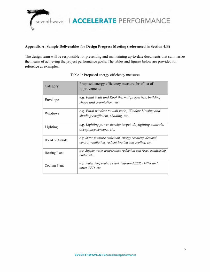
5
Appendix A: Sample Deliverables for Design Progress Meeting (referenced in Section 4.B) The design team will be responsible for presenting and maintaining up-to-date documents that summarize the means of achieving the project performance goals. The tables and figures below are provided for reference as examples.
Table 1: Proposed energy efficiency measures
Category Proposed energy efficiency measure: brief list of improvements
Envelope e.g. Final Wall and Roof thermal properties, building shape and orientation, etc.
Windows e.g. Final window to wall ratio, Window U value and shading coefficient, shading, etc.
Lighting e.g. Lighting power density target, daylighting controls, occupancy sensors, etc.
HVAC - Airside e.g. Static pressure reduction, energy recovery, demand control ventilation, radiant heating and cooling, etc.
Heating Plant e.g. Supply water temperature reduction and reset, condensing boiler, etc.
Cooling Plant e.g. Water temperature reset, improved EER, chiller and tower VFD, etc.
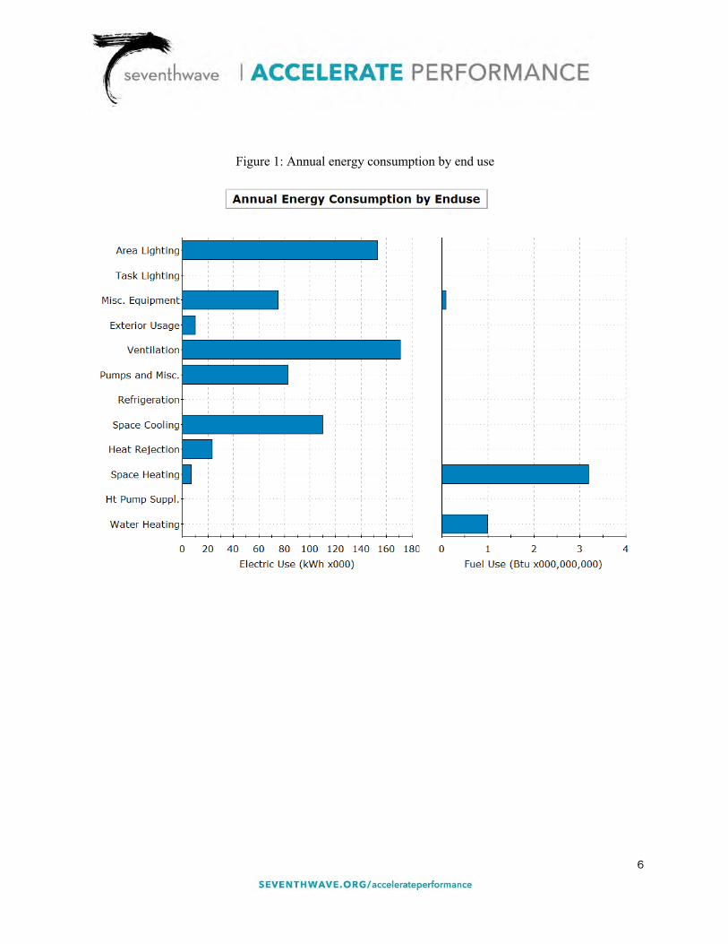
6
Figure 1: Annual energy consumption by end use
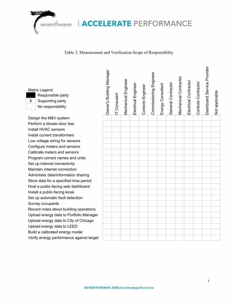
7
Table 2: Measurement and Verification Scope of Responsibility
Matrix Legend
Ow
ner's
Bui
ldin
g M
anag
er
IT C
onsu
lant
Mec
hani
cal E
ngin
eer
Elec
trica
l Eng
inee
r
Con
trols
Eng
inee
r
Com
mis
sion
ing
Engi
neer
Ener
gy C
onsu
ltant
Gen
eral
Con
tract
or
Mec
hani
cal C
ontra
ctor
Elec
trica
l Con
tract
or
Con
trols
Con
tract
or
Das
hboa
rd S
ervi
ce P
rovi
der
Not
app
licab
le
Responsible party X Supporting party No responsibility
Design the M&V system Perform a blower-door test Install HVAC sensors Install current transformers Low voltage wiring for sensors Configure meters and sensors Calibrate meters and sensors Program correct names and units Set up internet connectivity Maintain internet connection Administer data/information sharing Store data for a specified time period Host a public-facing web dashboard Install a public-facing kiosk Set up automatic fault detection Survey occupants Record notes about building operations Upload energy data to Portfolio Manager Upload energy data to City of Chicago Upload energy data to LEED Build a calibrated energy model Verify energy performance against target


3. Preliminary SD Energy Model Study


DRAFT – SD Energy Model Study
Arlington High SchoolMassachusetts AvenueArlington, MA
January 30, 2019
Project # 181230-000
PRELIMINARY - SD Energy Model Study

Arlington High School – SD Energy Model Study Page 2
TABLE OF CONTENTS
1. EXECUTIVE SUMMARY
2. ENERGY MODEL RESULTS
3. ENERGY MODEL INPUTS
4. APPENDIX – DETAILED BUILDING OCCUPANCY

Arlington High School – SD Energy Model Study Page 3
1. EXECUTIVE SUMMARY
A series of energy models have been developed for the new Arlington High School building. Arlington HighSchool will be a 413,300 sf high school facility in Arlington, Massachusetts. The building features standardclassrooms, maker space, an auditorium, gymnasium, administrative office space, and a central spine withcommons/plaza-type areas. In addition to normal school-day occupancy, there will be after-hours andweekend usage for community activity and afterschool programs.
The school is pursuing a net zero energy (NZE) design. In light of this goal, a number of energyconservation measure (ECM) alternates have been developed for the schematic design phase in order toexplore potential areas for improvement in site energy consumption.
The following table shows a description of each ECM, as well as total site energy, energy use intensity (EUI),and percent change for each alternate. Refer to the Appendix section of this report for a detailed descriptionof envelope performance values for the baseline design and envelope alternates.
DESIGN ALTERNATESUMMARY
DESCRIPTION
ANNUALELECTRICITY
CONSUMPTION(KWH)
ANNUALELECTRICITY
SAVINGS(KWH)
EUI(kbtu/sf/yr)
% Changefrom Baseline
Model
Baseline Model (SDProposed Design)
Proposed design per 1/14/2019 SDPricing set· Avg classroom wing WWR: 51%· Avg whole-building WWR: 33%
3,970,574 - 32.78 -
Envelope Alt-AAdded opaque wall insulation at Athletic& Performing Arts Wings, change to triple-pane glass on North elevations
3,940,152 30,422 32.53 0.8%
Envelope Alt-BAlt-A plus opaque wall insulation at CRWings, change to triple-pane glass onS/E/W elevations
3,906,741 63,834 32.25 1.6%
Envelope Alt-CVacuum double-pane glass on Northelevations
3,913,277 57,298 32.31 1.4%
Envelope Alt-DAlt-C plus double-pane glass on S/E/Welevations
3,805,363 165,211 31.42 4.2%
Heat Recovery AltEnthalpy heat recovery wheels added toall recirculating RTU's.
3,801,700 168,875 31.38 4.3%
Window Reduction Alt-A
90% reduction factor applied across allwindows.· Avg classroom wing WWR: 46%· Avg whole-building WWR: 30%
3,949,326 21,249 32.60 0.5%
Window Reduction Alt-B
80% reduction factor applied acrossbuilding.· Avg classroom wing WWR: 41%· Avg whole-building WWR: 27%
3,923,036 47,538 32.39 1.2%
Combined Alt-A· Envelope Alt-B· Window Reduction Alt-B (80%)
3,867,292 103,283 31.93 2.6%
Combined Alt-B· Envelope Alt-D· Window Reduction Alt-B (80%)
3,769,607 200,967 31.12 5.1%
Combined Alt-C· Envelope Alt-B· Window Reduction Alt-B (80%)· Heat Recovery Alt
3,687,075 283,499 30.44 7.1%
Combined Alt-D· Envelope Alt-D· Window Reduction Alt-B (80%)· Heat Recovery Alt
3,580,715 389,859 29.56 9.8%

Arlington High School – SD Energy Model Study Page 4
Energy Model Images
Northwest Corner View
Southeast Corner View
Energy Modeling Disclaimer
Building energy modeling is a comparative tool used for understanding the relative impact of alternate strategiesand systems on annual energy use and cost. Energy modeling is not an absolute predictor of actual energy useor cost and shall not be relied on to predict actual building performance. Changes in construction, variableweather conditions, operational characteristics, end-user input, miscellaneous electrical and gas loads, controlsalterations and other unpredictable metrics prevent energy models from predicting the actual annual energyconsumption of any facility.

Arlington High School – SD Energy Model Study Page 5
2. ENERGY MODEL RESULTS
The below charts show site energy consumption for the baseline SD model, broken out into variouscategories in order to understand how and when the building uses energy.

Arlington High School – SD Energy Model Study Page 6

Arlington High School – SD Energy Model Study Page 7
3. ENERGY MODEL INPUTS
Project and Site Information
Weather Boston, MA – TMY2 format
Orientation Plan North = North-Northwest
Schedule and Occupancy
A detailed annual schedule has been incorporated into the energy model based on Arlington High School’sactual operational schedule and projected building occupation. The below heatmap describes the overallprogram intensity throughout the year and by time of day. Building program intensity is positively correlated withthe intensity of red in the diagram.
Occupancy schedules include “VacationFun” and “SummerFun” programs, winter and summer recess, as wellas scheduled holidays outlined in the following section. Additional major program types include schedules forregular classrooms, extended classrooms, gym spaces, auditorium spaces, community school offices and districtadmin offices. Extended hour programs use classrooms on floors 1-3 of the “Humanities Wing” and floor 2 ofthe “Steam Wing”. Extended hour programs also use Athletic and Performing Arts wings in addition tocommunity admin offices. Refer to the Appendix section of this report for similar heatmaps for each majorprogram type.
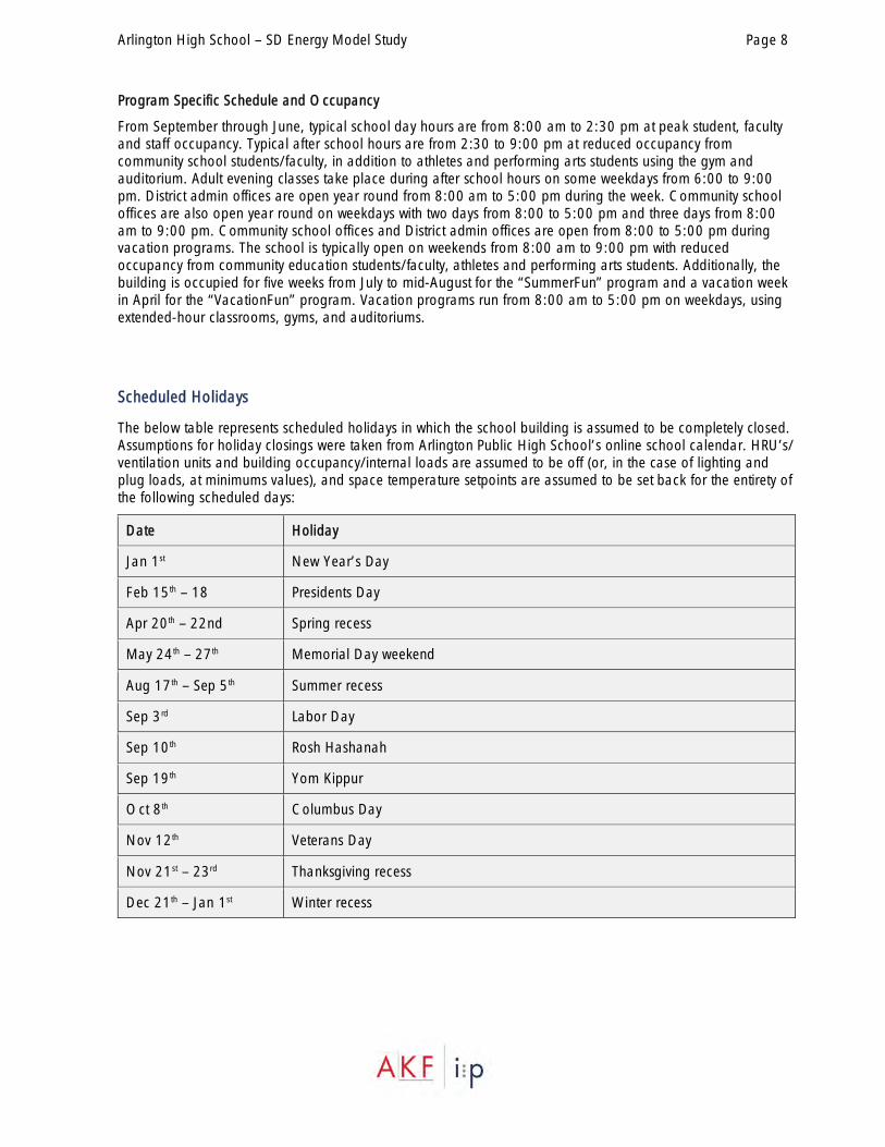
Arlington High School – SD Energy Model Study Page 8
Program Specific Schedule and Occupancy
From September through June, typical school day hours are from 8:00 am to 2:30 pm at peak student, facultyand staff occupancy. Typical after school hours are from 2:30 to 9:00 pm at reduced occupancy fromcommunity school students/faculty, in addition to athletes and performing arts students using the gym andauditorium. Adult evening classes take place during after school hours on some weekdays from 6:00 to 9:00pm. District admin offices are open year round from 8:00 am to 5:00 pm during the week. Community schooloffices are also open year round on weekdays with two days from 8:00 to 5:00 pm and three days from 8:00am to 9:00 pm. Community school offices and District admin offices are open from 8:00 to 5:00 pm duringvacation programs. The school is typically open on weekends from 8:00 am to 9:00 pm with reducedoccupancy from community education students/faculty, athletes and performing arts students. Additionally, thebuilding is occupied for five weeks from July to mid-August for the “SummerFun” program and a vacation weekin April for the “VacationFun” program. Vacation programs run from 8:00 am to 5:00 pm on weekdays, usingextended-hour classrooms, gyms, and auditoriums.
Scheduled Holidays
The below table represents scheduled holidays in which the school building is assumed to be completely closed.Assumptions for holiday closings were taken from Arlington Public High School’s online school calendar. HRU’s/ventilation units and building occupancy/internal loads are assumed to be off (or, in the case of lighting andplug loads, at minimums values), and space temperature setpoints are assumed to be set back for the entirety ofthe following scheduled days:
Date Holiday
Jan 1st New Year’s Day
Feb 15th – 18 Presidents Day
Apr 20th – 22nd Spring recess
May 24th – 27th Memorial Day weekend
Aug 17th – Sep 5th Summer recess
Sep 3rd Labor Day
Sep 10th Rosh Hashanah
Sep 19th Yom Kippur
Oct 8th Columbus Day
Nov 12th Veterans Day
Nov 21st – 23rd Thanksgiving recess
Dec 21th – Jan 1st Winter recess
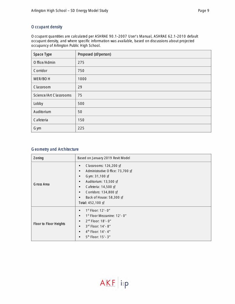
Arlington High School – SD Energy Model Study Page 9
Occupant density
Occupant quantities are calculated per ASHRAE 90.1-2007 User’s Manual, ASHRAE 62.1-2010 defaultoccupant density, and where specific information was available, based on discussions about projectedoccupancy of Arlington Public High School.
Space Type Proposed (sf/person)
Office/Admin 275
Corridor 750
MER/BOH 1000
Classroom 29
Science/Art Classrooms 75
Lobby 500
Auditorium 50
Cafeteria 150
Gym 225
Geometry and Architecture
Zoning Based on January 2019 Revit Model
Gross Area
§ Classrooms: 126,200 sf
§ Administrative Office: 73,700 sf
§ Gym: 31,100 sf
§ Auditorium: 13,500 sf
§ Cafeteria: 14,500 sf
§ Corridors: 134,800 sf
§ Back of House: 58,300 sf
Total: 452,100 sf
Floor to Floor Heights
§ 1st Floor: 12’- 0”
§ 1st Floor Mezzanine: 12’- 0”
§ 2nd Floor: 18’- 0”
§ 3rd Floor: 14’- 8”
§ 4th Floor: 14’- 4”
§ 5th Floor: 15’- 3”
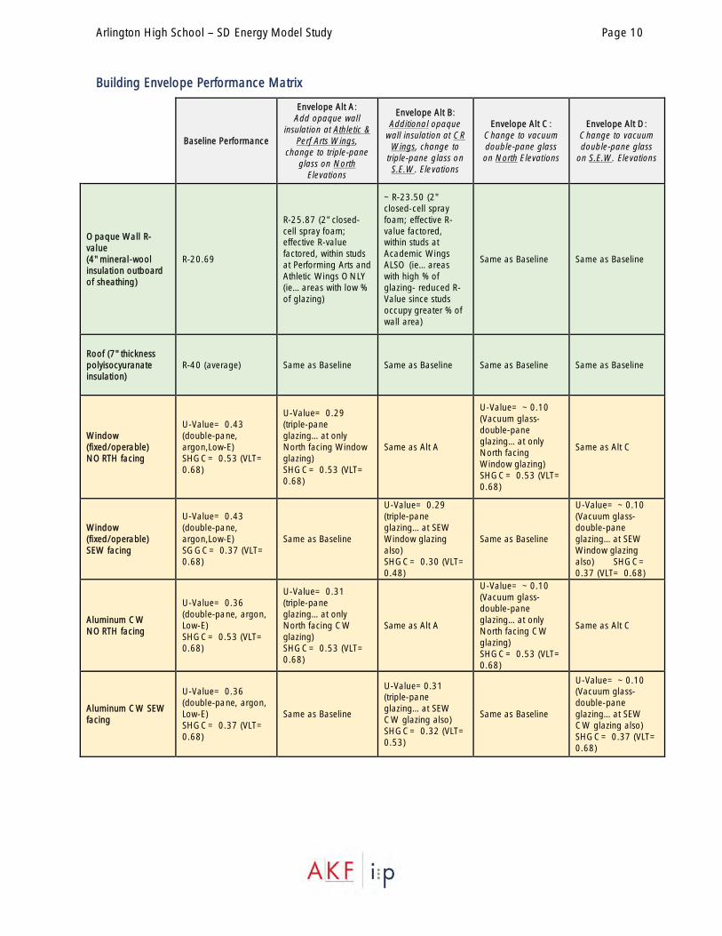
Arlington High School – SD Energy Model Study Page 10
Building Envelope Performance Matrix
Baseline Performance
Envelope Alt A:Add opaque wall
insulation at Athletic &Perf Arts Wings,
change to triple-paneglass on North
Elevations
Envelope Alt B:Additional opaque
wall insulation at CRWings, change to
triple-pane glass onS.E.W. Elevations
Envelope Alt C:Change to vacuumdouble-pane glasson North Elevations
Envelope Alt D:Change to vacuumdouble-pane glass
on S.E.W. Elevations
Opaque Wall R-value(4" mineral-woolinsulation outboardof sheathing)
R-20.69
R-25.87 (2" closed-cell spray foam;effective R-valuefactored, within studsat Performing Arts andAthletic Wings ONLY(ie…areas with low %of glazing)
~R-23.50 (2"closed-cell sprayfoam; effective R-value factored,within studs atAcademic WingsALSO (ie…areaswith high % ofglazing- reduced R-Value since studsoccupy greater % ofwall area)
Same as Baseline Same as Baseline
Roof (7" thicknesspolyisocyuranateinsulation)
R-40 (average) Same as Baseline Same as Baseline Same as Baseline Same as Baseline
Window(fixed/operable)NORTH facing
U-Value= 0.43(double-pane,argon,Low-E)SHGC= 0.53 (VLT=0.68)
U-Value= 0.29(triple-paneglazing…at onlyNorth facing Windowglazing)SHGC= 0.53 (VLT=0.68)
Same as Alt A
U-Value= ~0.10(Vacuum glass-double-paneglazing…at onlyNorth facingWindow glazing)SHGC= 0.53 (VLT=0.68)
Same as Alt C
Window(fixed/operable)SEW facing
U-Value= 0.43(double-pane,argon,Low-E)SGGC= 0.37 (VLT=0.68)
Same as Baseline
U-Value= 0.29(triple-paneglazing…at SEWWindow glazingalso)SHGC= 0.30 (VLT=0.48)
Same as Baseline
U-Value= ~0.10(Vacuum glass-double-paneglazing…at SEWWindow glazingalso) SHGC=0.37 (VLT= 0.68)
Aluminum CWNORTH facing
U-Value= 0.36(double-pane, argon,Low-E)SHGC= 0.53 (VLT=0.68)
U-Value= 0.31(triple-paneglazing…at onlyNorth facing CWglazing)SHGC= 0.53 (VLT=0.68)
Same as Alt A
U-Value= ~0.10(Vacuum glass-double-paneglazing…at onlyNorth facing CWglazing)SHGC= 0.53 (VLT=0.68)
Same as Alt C
Aluminum CW SEWfacing
U-Value= 0.36(double-pane, argon,Low-E)SHGC= 0.37 (VLT=0.68)
Same as Baseline
U-Value=0.31(triple-paneglazing…at SEWCW glazing also)SHGC= 0.32 (VLT=0.53)
Same as Baseline
U-Value= ~0.10(Vacuum glass-double-paneglazing…at SEWCW glazing also)SHGC= 0.37 (VLT=0.68)

Arlington High School – SD Energy Model Study Page 11
Miscellaneous Envelope Performance (same for all options)
Sunshades South facing windows, CW to have sunshades
Opaque Doors U= 0.37
Skylights- Unit Skylights U= 0.45, SHGC= 0.34, VLT=0.43
Skylights- sloped glazing U=0.36, SHGC= 0.37, VLT=0.68
Internal Electrical Loads
Proposed Design
Lighting § All spaces: 0.45 W/sf (assumed)
Specialty Lighting
§ Auditorium stage lighting: 80 kW peak, assumed diversity 5% mon-thur, 100%from 3 – 7 pm fri and 4 – 6pm sat, 0% otherwise
§ Blackbox stage lighting: 15 kW peak, assumed diversity same as auditorium
§ Exterior lighting: 10 kW peak, 0% from 8 am – 9pm, 100% during unoccupiedhours
Daylighting Daylighting in all primary sidelighted areas
Equipment(includes diversity)
§ Classroom/Science/Art spaces: 0.5 W/sf§ CAD Lab: 0.75 W/sf§ Office/Admin spaces: 0.75 W/sf§ Gym/Auditorium/Corridor: 0.5 W/sf
§ BOH spaces: 0.25 W/sf
Specialty Equipment
§ Kitchen Load: 200 kW peak, assumed diversity 55% during weekdays from8am – 2pm, 5% after hours, 0% during weekends and holidays
§ Elevator Load: 10 kW peak, assumed diversity 30% during day, 0% at night(off fully during holidays)
§ IT Load: 10 kW peak, assumed diversity 80% during day and 40% at night(year round)

Arlington High School – SD Energy Model Study Page 12
Airside HVAC Performance Details
Airside Systems Proposed Design
Thermostat Setpoints · 75oF Cooling / 70oF Heating· Setback: 80oF Cooling / 65oF Heating during unoccupied hours
Air Systems
Classroom Spaces (including corridors)
§ 4-pipe Chilled Beam System (CHW/HW) with 100% OA Heat Recovery Unit(CHW/HW)
§ HRU Systems supply / return fan static: 6” / 3.5” (assumed)
§ 100% OA HRU’s 1,2,3,4 supply ventilation air, and are assumed to turn downduring reduced building occupation hours.
§ Ventilation: 66,233 cfm
Administrative Office / Preschool / Community Spaces
§ Air-cooled VRF System with Heat Recovery, 100% OA Energy Recovery Unit(CHW/HW)
§ VRF Systems supply fan static: 1” (assumed)§ ERU Systems supply / return fan static: 5” / 2.5” (assumed)
§ Ventilation: 24,100 cfm
Auditorium Spaces (RTU-1, 2, 3, 4)
§ Rooftop Variable Air Volume System (CHW/HW) with Demand ControlledVentilation (DCV)
§ Supply / return fan static: 5” / 3” (assumed)
§ Supply flow: 47,797 cfm§ Ventilation: 30% OA (assumed)
Gym Spaces (RTU-5, 6)§ Rooftop Variable Air Volume System (CHW/HW) with DCV
§ Supply / return fan static: 5” / 3” (assumed)§ Supply flow: 49,588 cfm
§ Ventilation: 30% OA (assumed)
Central Hallway Spaces (RTU-7, 8 , 9)§ Rooftop Variable Air Volume System (CHW/HW) with DCV
§ Supply / return fan static: 5” / 3” (assumed)§ Supply flow: 78,526 cfm
§ Ventilation: 30% OA (assumed)

Arlington High School – SD Energy Model Study Page 13
Cafeteria Spaces (RTU-10)
§ Rooftop Variable Air Volume System (CHW/HW) with DCV§ Supply / return fan static: 5” / 3” (assumed)§ Supply flow: 31,125 cfm
§ Ventilation: 30% OA (assumed)
Kitchen Space (HV-1)§ Heating and Ventilation System, 100% OA
§ HV System supply fan static: 2.5”§ Ventilation: 8,000 cfm
BOH Spaces:§ Electric Unit Heaters
Economizer Dual Enthalpy Economizer on recirculating units (RTU’s)
Energy Recovery Proposed: Enthalpy Wheel on 100% OA Heat Recovery Units serving class wingsand 100% OA Energy Recovery Units serving Admin/Community/Pre K spaces76% Sensible / 74% Latent Effectiveness
Proposed Alternates with Heat Recovery: Enthalpy Wheel on all recirculating RooftopUnits
76% Sensible / 74% Latent Effectiveness

Arlington High School – SD Energy Model Study Page 14
Waterside HVAC Performance Details
Waterside Systems Proposed Design
CHW Source Heat recovery chillers, COP-6.0, fed from geothermal well loop
CHW Temperatures 45 oF supply primary / 57 oF supply secondary for chilled beam systems
CHW Flow Variable Primary/Secondary pumps
CHW Pump 85 ft. head
CHW Reset 45 oF supply at 80 oF and above, 55 oF supply at 60 oF and below; ramped linearly inbetween
HW Source Heat recovery chillers, COP-6.0, fed from geothermal well loop
HW Temperatures 130 oF supply at 20 oF OAT and below, 100 oF supply at 50 oF OAT and above;ramped linearly in between
HW Flow Variable Primary
HW Pump 85 ft. head
Well Loop Flow/Pump Variable Primary / 100 ft. head
Domestic Hot Water
Proposed Design
General UsagePeak values are taken from ASHRAE 90.1-2007 User’s Manual, and are based onanticipated occupancy and Btu/person hot water demand:§ School Peak Load: 1.368 MBtu/h
Heaters Domestic Hot Water Heater: ~80% efficient (assumed)

Arlington High School – SD Energy Model Study Page 15
Appendix: Detailed Occupancy Heatmaps
The below heatmaps show the modeled program intensity throughout the year and time-of-day for majorprogram types. Because most energy simulation engines limit schedule assignments to single-hour increments,and because of the ways in which occupancy/load diversity are described within thermal zones, some amount ofdeviation from the exact program schedules as listed in the report is to be expected. However, the overallseasonal, weekly, and daily trends for each space type are captured as described within the report.

Arlington High School – SD Energy Model Study Page 16

Arlington High School – SD Energy Model Study Page 17


4. Proprietary Items


Arlington High School Arlington, Massachusetts
Schematic Design Project Manual
Page -1
SCHEMATIC DESIGN
Project Manual Appendix 4
Proprietary Items List
The following items are the recommended items to be proprietary per the Town and School Department to insure a standard of quality of materials and reliability throughout the school district and Town of Arlington, which will allow for: standardized stock items for repairs or replacement parts; standardized operation and maintenance of system-wide with Facilities, IT and outside service providers; and the seamless integration with the Police and Fire Departments.
• Automatic Temperature Controls (ATC) System: Johnson Controls to operate their Facility
Explorer (FX) automation platform. (Network protocols and communication would be open
BACnet allowing ATC vendor of the Owner’s choosing to repair, operate, or amend system).
Johnson Controls BMS system shall integrate with separate stand-alone (ICONICS) building
monitoring software purchased by Owner.
• Fire alarm Control Panel: NESCO/Notifier
• Door Hardware Exit Devices: Von Duprin
• Door Hardware locksets: BEST Access Systems
• Security film for security glazing applications: School Guard Glass by LTI Smart Glass, Inc.
• Security System Network Control Panel: Avigilon/Mercury
• Security Cameras: Avigilon Access Control
• Video Intercom System: Avigilon SIP model
Further assessment of these products/systems will be performed in the Design Development Phase to confirm that
it is in the public interest that these items be proprietary. It is anticipated that the Design Development MSBA
Submission will contain a finalized list along with the required certification by the Arlington High School Building
Committee.


5. Schematic Design Room Finishes Schedule

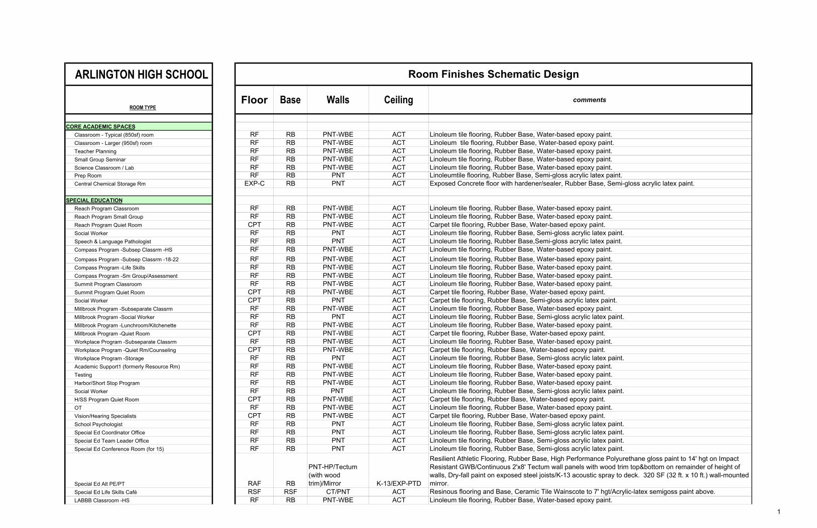
ARLINGTON HIGH SCHOOL
ROOM TYPEFloor Base Walls Ceiling comments
Classroom - Typical (850sf) room RF RB PNT-WBE ACT Linoleum tile flooring, Rubber Base, Water-based epoxy paint.
Classroom - Larger (950sf) room RF RB PNT-WBE ACT Linoleum tile flooring, Rubber Base, Water-based epoxy paint.
Teacher Planning RF RB PNT-WBE ACT Linoleum tile flooring, Rubber Base, Water-based epoxy paint.
Small Group Seminar RF RB PNT-WBE ACT Linoleum tile flooring, Rubber Base, Water-based epoxy paint.
Science Classroom / Lab RF RB PNT-WBE ACT Linoleum tile flooring, Rubber Base, Water-based epoxy paint.Prep Room RF RB PNT ACT Linoleumtile flooring, Rubber Base, Semi-gloss acrylic latex paint.
Central Chemical Storage Rm EXP-C RB PNT ACT Exposed Concrete floor with hardener/sealer, Rubber Base, Semi-gloss acrylic latex paint.
SPECIAL EDUCATION
Reach Program Classroom RF RB PNT-WBE ACT Linoleum tile flooring, Rubber Base, Water-based epoxy paint.
Reach Program Small Group RF RB PNT-WBE ACT Linoleum tile flooring, Rubber Base, Water-based epoxy paint.
Reach Program Quiet Room CPT RB PNT-WBE ACT Carpet tile flooring, Rubber Base, Water-based epoxy paint.
Social Worker RF RB PNT ACT Linoleum tile flooring, Rubber Base, Semi-gloss acrylic latex paint.
Speech & Language Pathologist RF RB PNT ACT Linoleum tile flooring, Rubber Base,Semi-gloss acrylic latex paint.
Compass Program -Subsep Classrm -HS RF RB PNT-WBE ACT Linoleum tile flooring, Rubber Base, Water-based epoxy paint.
Compass Program -Subsep Classrm -18-22 RF RB PNT-WBE ACT Linoleum tile flooring, Rubber Base, Water-based epoxy paint.
Compass Program -Life Skills RF RB PNT-WBE ACT Linoleum tile flooring, Rubber Base, Water-based epoxy paint.
Compass Program -Sm Group/Assessment RF RB PNT-WBE ACT Linoleum tile flooring, Rubber Base, Water-based epoxy paint.
Summit Program Classroom RF RB PNT-WBE ACT Linoleum tile flooring, Rubber Base, Water-based epoxy paint.
Summit Program Quiet Room CPT RB PNT-WBE ACT Carpet tile flooring, Rubber Base, Water-based epoxy paint.
Social Worker CPT RB PNT ACT Carpet tile flooring, Rubber Base, Semi-gloss acrylic latex paint.
Millbrook Program -Subseparate Classrm RF RB PNT-WBE ACT Linoleum tile flooring, Rubber Base, Water-based epoxy paint.
Millbrook Program -Social Worker RF RB PNT ACT Linoleum tile flooring, Rubber Base, Semi-gloss acrylic latex paint.
Millbrook Program -Lunchroom/Kitchenette RF RB PNT-WBE ACT Linoleum tile flooring, Rubber Base, Water-based epoxy paint.
Millbrook Program -Quiet Room CPT RB PNT-WBE ACT Carpet tile flooring, Rubber Base, Water-based epoxy paint.
Workplace Program -Subseparate Classrm RF RB PNT-WBE ACT Linoleum tile flooring, Rubber Base, Water-based epoxy paint.
Workplace Program -Quiet Rm/Counseling CPT RB PNT-WBE ACT Carpet tile flooring, Rubber Base, Water-based epoxy paint.
Workplace Program -Storage RF RB PNT ACT Linoleum tile flooring, Rubber Base, Semi-gloss acrylic latex paint.
Academic Support1 (formerly Resource Rm) RF RB PNT-WBE ACT Linoleum tile flooring, Rubber Base, Water-based epoxy paint.
Testing RF RB PNT-WBE ACT Linoleum tile flooring, Rubber Base, Water-based epoxy paint.
Harbor/Short Stop Program RF RB PNT-WBE ACT Linoleum tile flooring, Rubber Base, Water-based epoxy paint.
Social Worker RF RB PNT ACT Linoleum tile flooring, Rubber Base, Semi-gloss acrylic latex paint.
H/SS Program Quiet Room CPT RB PNT-WBE ACT Carpet tile flooring, Rubber Base, Water-based epoxy paint.
OT RF RB PNT-WBE ACT Linoleum tile flooring, Rubber Base, Water-based epoxy paint.
Vision/Hearing Specialists CPT RB PNT-WBE ACT Carpet tile flooring, Rubber Base, Water-based epoxy paint.
School Psychologist RF RB PNT ACT Linoleum tile flooring, Rubber Base, Semi-gloss acrylic latex paint.
Special Ed Coordinator Office RF RB PNT ACT Linoleum tile flooring, Rubber Base, Semi-gloss acrylic latex paint.
Special Ed Team Leader Office RF RB PNT ACT Linoleum tile flooring, Rubber Base, Semi-gloss acrylic latex paint.
Special Ed Conference Room (for 15) RF RB PNT ACT Linoleum tile flooring, Rubber Base, Semi-gloss acrylic latex paint.
Special Ed Alt PE/PT RAF RB
PNT-HP/Tectum
(with wood
trim)/Mirror K-13/EXP-PTD
Resilient Athletic Flooring, Rubber Base, High Performance Polyurethane gloss paint to 14' hgt on Impact
Resistant GWB/Continuous 2'x8' Tectum wall panels with wood trim top&bottom on remainder of height of
walls, Dry-fall paint on exposed steel joists/K-13 acoustic spray to deck. 320 SF (32 ft. x 10 ft.) wall-mounted
mirror.
Special Ed Life Skills Café RSF RSF CT/PNT ACT Resinous flooring and Base, Ceramic Tile Wainscote to 7' hgt/Acrylic-latex semigoss paint above.
LABBB Classroom -HS RF RB PNT-WBE ACT Linoleum tile flooring, Rubber Base, Water-based epoxy paint.
CORE ACADEMIC SPACES
Room Finishes Schematic Design
1

ARLINGTON HIGH SCHOOL
ROOM TYPEFloor Base Walls Ceiling comments
Room Finishes Schematic Design
LABBB Classroom -18-22 RF RB PNT-WBE ACT Linoleum tile flooring, Rubber Base, Water-based epoxy paint.
LABBB Common Space RF RB PNT-WBE ACT Linoleum tile flooring, Rubber Base, Water-based epoxy paint.
LABBB Nurse (T/Office/Rest) RF RB PNT-WBE ACT Linoleum tile flooring, Rubber Base, Water-based epoxy paint.
LABBB Nurse Toilet RSF RSF CT/PNT ACT Resinous flooring and Base, Ceramic Tile Wainscote to 7' hgt/Acrylic-latex semigoss paint above.
LABBB Quiet Room CPT RB PNT-WBE ACT Carpet tile flooring, Rubber Base, Water-based epoxy paint.
LABBB Open Office (4) RF RB PNT ACT Linoleum tile flooring, Rubber Base, Semi-gloss acrylic latex paint.
LABBB OT/PT RF RB PNT-WBE ACT Linoleum tile flooring, Rubber Base, Water-based epoxy paint.
LABBB Storage RF RB PNT ACT Linoleum tile flooring, Rubber Base, Semi-gloss acrylic latex paint.
ART & MUSIC
Art Classroom AFC 1 RB
PNT-WBE/ ACC
panels
K-13/EXP-PTD/
ACC Clouds
Polished-Dyed concrete flooring, Rubber Base, Water-based epoxy paint on walls/250sf Accoustic Wall
panels, Dry-fall paint on exposed beams/K-13 acoustic spray to deck/Suspended accoustic clouds
Art Workroom w/ Storage & kiln AFC 1 RB PNT-WBE K-13/EXP-PTD
Polished-Dyed concrete flooring, Rubber Base, Water-based epoxy paint on walls, Dry-fall paint on exposed
beams/K-13 acoustic spray to deck.
Band AFC 1 RB
PNT-WBE/ ACC
panels
K-13/EXP-PTD/
ACC Clouds
Polished-Dyed concrete flooring, Rubber Base, Water-based epoxy paint on walls/700 sf of Accoustic
panels, Dry-fall paint on exposed steel joists, K-13 acoustic spray to deck/Suspended accoustic clouds
Chorus RF RB
PNT-WBE/ ACC
panels
K-13/EXP-PTD/
ACC Clouds
Linoleum tile, Rubber Base, Water-based epoxy paint on walls/500sf ACC panels, Dry-fall paint on
exposedsteel joists, K-13 acoustic spray to deck/ Suspended accoustic clouds
Performing Arts
STAGE
Flooring VCB
PNT-WBE/ ACC
panels
K-13/EXP-PTD/
ACC Clouds
Painted Hardboard on sprung/plywood flooring, Ventilating Rubber Base, Water-based epoxy paint on
walls/700 sf Accoustic panels, Dry-fall paint on exposed beams/K-13 acoustic spray to deck/ Suspended
accoustic clouds
Control Room RF RB PNT-WBE
ACT- $$ (black tile
and grid) Linoleum tile flooring, Rubber Base, Water-based epoxy paint.
Ensemble RF RB PNT-WBE
K-13/EXP-PTD/
ACC Clouds
Linoleum tile, Rubber Base, Water-based epoxy paint on walls, Dry-fall paint on exposed beams/K-13
acoustic spray to deck/ Suspended accoustic clouds
Music Practice AFC 1 RB PNT-WBE ACT Polished-Dyed concrete flooring, Rubber Base, Water-based epoxy paint
Music Instrument Storage AFC-1 RB PNT ACT Polished-Dyed concrete flooring, Rubber Base, Semi-gloss acrylic latex paint.
VOCATIONS & TECHNOLOGY
Makerspace/ Wood Shop AFC 1 RB
PNT-WBE/ ACC
panels/ Pegboard
K-13/EXP-PTD/
ACC Clouds
Polished-Dyed concrete flooring, Rubber Base, Water-based epoxy paint on walls/500sf Accoustic
Panels/200sf of pegboard with accosutic batt insulation behind, Dry-fall paint on exposed beams/K-13
acoustic spray to deck/ Suspended accoustic clouds
Engineering/Wood Shop AFC 1 RB
PNT-WBE/ ACC
panels/ Pegboard
K-13/EXP-PTD/
ACC Clouds
Polished-Dyed concrete flooring, Rubber Base, Water-based epoxy paint on walls/500sf Accoustic
Panels/200sf of pegboard with accosutic batt insulation behind, Dry-fall paint on exposed beams/K-13
acoustic spray to deck/ Suspended accoustic clouds
CADD Lab AFC 1 RB PNT-WBE
K-13/EXP-PTD
/ACC Clouds
Polished-Dyed concrete flooring, Rubber Base, Water-based epoxy paint on walls, Dry-fall paint on exposed
beams/K-13 acoustic spray to deck/ Suspended accoustic clouds
STEM Lab/ Computer Science Lab RF RB PNT-WBE ACT Linoleum tile flooring, Rubber Base, Water-based epoxy paint.
2

ARLINGTON HIGH SCHOOL
ROOM TYPEFloor Base Walls Ceiling comments
Room Finishes Schematic Design
Digital Arts Lab AFC 1 RB PNT-WBE
K-13/EXP-PTD/
ACC Clouds/ACC
panels
Polished-Dyed concrete flooring, Rubber Base, Water-based epoxy paint on walls/250sf Accoustic Panels,
Dry-fall paint on exposed beams/K-13 acoustic spray to deck/ Suspended accoustic clouds
Digital Production Lab CPT RB
PNT-WBE/ACC
panels (green
screen) ACT Carpet tile flooring, Rubber Base, Water-based epoxy paint/100sf Accoustic Panels.
Production Studio CPT RB
PNT-WBE/ACC
panels ACT
Carpet tile flooring, Rubber Base, Water-based epoxy paint/250 SF Accoustic panels. (There will also be a
green screen in this room).
Language Lab/Multi-Media Immersion Lab RF RB PNT-WBE ACT Linoleum tile flooring, Rubber Base, Water-based epoxy paint.
Computer Lab/ Smart Center/ Clean Lab RF RB PNT-WBE ACT Linoleum tile flooring, Rubber Base, Water-based epoxy paint.
FACS AFC 1 RB PNT-WBE ACT Linoleum tile flooring, Rubber Base, Water-based epoxy paint.
Daycare/ ECE RF RB PNT-WBE ACT Linoleum tile flooring, Rubber Base, Water-based epoxy paint.
Dayvcare CR Toilet Room RSF RSF PNT/CT ACT Resinous flooring, Resinous Base, Water-based epoxy paint/CT wainscote (7' high)
Daycare - sleeping room CPT RB PNT-WBE ACT Carpet tile flooring, Rubber Base, Water-based epoxy paint.
Discourse Lab RF/CPT RB
PNT-WBE/ACC
panels
K-13/EXP-PTD/
ACC Clouds
Linoleum tile flooring @lecture area/Carpet at stepped aisles/sealed concrete under seats, Rubber Base,
Water-based epoxy paint on walls/Wood Accoustic Panels on 50% of wall area, Dry-fall paint on exposed
beams/K-13 acoustic spray to deck/ Suspended accoustic clouds
HEALTH & PHYSICAL EDUCATION
Gymnasium WAF VCB
PNT-HP/Tectum
(with wood trim) K-13/EXP-PTD
Wood Athletic Flooring, Ventilating Rubber Base, High Performance Polyurethane gloss paint to 14' hgt on
Impact Resistant GWB/Continuous 2'x8' Tectum wall panels with wood trim top&bottom on remainder of
height of walls, Dry-fall paint on exposed steel joists/K-13 acoustic spray to deck. (Impact GWB need not
occur behind bleachers).
Gymnasium RAF RB
PNT-HP/Tectum
(with wood trim) K-13/EXP-PTD
Resilient Athletic Flooring, Rubber Base, High Performance Polyurethane gloss paint to 14' hgt on Impact
Resistant GWB/Continuous 2'x8' Tectum wall panels with wood trim top&bottom on remainder of height of
walls, Dry-fall paint on exposed steel joists/K-13 acoustic spray to deck. 160 LF of wall padding - 6 Ft. high.
PE Alternatives -Fitness Center IFT RB
PNT-HP/Tectum
(with wood
trim)/Mirror K-13/EXP-PTD
Interlocking Rubber Floor Tile, Rubber Base, High Performance Polyurethane gloss paint on (impact
resistant GWB) walls/1000sf Tectum with wood trim top and bottom, Dry-fall paint on exposed beams/K-13
acoustic spray to deck. 100 SF (10 ft. x 10 ft.) of wall-mounted mirror
Gym Storeroom EXP-C RB PNT-WBE ACT- $ Exposed Concrete floor with hardener/sealer, Rubber Base, Water-based epoxy paint.
Locker Rooms - Boys / Girls w/ Toilets AFC 1 RB PNT-HP
CWFP (Tectum)
Panels
Polished-Dyed concrete flooring, Rubber Base, High Performance Polyurethane Gloss paint on (CMU) walls,
Suspended 2'x10' Tectum panels/Grid ceiling
Phys. Ed. Storage1 EXP-C RB PNT-WBE ACT Exposed Concrete floor with hardener/sealer, Rubber Base, Water-based epoxy paint.
Athletic Director's Office RF RB PNT ACT Linoleum tile flooring, Rubber Base, Semi-gloss acrylic latex paint.
Health Instructor's Office RF RB PNT ACT Linoleum tile flooring, Rubber Base, Semi-gloss acrylic latex paint.
Health Instructor's Tlt/Shower RSF RSF PNT/CT GWB-PNT
Resinous flooring, Resinous Base, Water-based epoxy paint/CT wainscote (7' high), Semigloss acrylic latex
paint on ceiling
Trainer's Room/Laundry/Ice RSF RSF PNT/CT GWB-PNT
Resinous flooring, Resinous Base, Water-based epoxy paint/CT wainscote (7' high), Semigloss acrylic latex
paint on ceiling
LIBRARY LEARNING COMMONS
Library Learning Commons CPT RB
PNT-WBE/ ACC
panels ACT Carpet tile flooring, Rubber Base, Water-based epoxy paint. 3000 SF of acoustic wall panels.
LLC -Workroom RF RB PNT ACT Linoleum tile flooring, Rubber Base, Semi-gloss acrylic latex paint.
LLC -Conference Room CPT RB PNT ACT Carpet tile flooring, Rubber Base, Semi-gloss acrylic latex paint.
3

ARLINGTON HIGH SCHOOL
ROOM TYPEFloor Base Walls Ceiling comments
Room Finishes Schematic Design
LLC -Office CPT RB PNT ACT Carpet tile flooring, Rubber Base, Semi-gloss acrylic latex paint.
LLC -Tech Storage RF RB PNT ACT Linoleum tile flooring, Rubber Base, Semi-gloss acrylic latex paint.
Learning Center CPT RB PNT-WBE ACT Carpet tile flooring, Rubber Base, Water-based epoxy paint.
AUDITORIUM / DRAMA
Auditorium EXP-C/CPT RB WD/PNT K-13/EXP-PTD
Exposed Concrete floor with hardener/sealer under seats and carpet at aisles, Rubber Base, Wood Acoustic
Paneling with Acrylic latex paint above, Dry-fall paint on exposed beams/K-13 acoustic spray to deck.
Painted catwalk.
Stage STAGEFlng VCB PNT-WBE
K-13/EXP-PTD/
ACC Clouds
Painted Hardboard on sprung/plywood flooring, Ventilating Rubber Base, Water-based epoxy paint on walls,
Dry-fall paint on exposed beams/K-13 acoustic spray to deck/Suspended Accoustic Clouds
Auditorium Storage EXP-C RB PNT ACT Exposed Concrete floor with hardener/sealer, Rubber Base, Semi-gloss acrylic latex paint.
Make-up / Dressing Rooms AFC 1 RB PNT-WBE ACT Polished-dyed concrete floor, Rubber Base, Water-based epoxy paint.
Controls / Lighting / Projection RF RB PNT-WBE
ACT (black tile and
grid) Linoleum tile flooring, Rubber Base, Water-based epoxy paint.
DINING & FOOD SERVICE
Cafeteria PCT/EM PCT
PNT/CT/Brick/WR
panels ACT
Porcelain Floor Tile and Base/ Entry Matt at north entry area (15' length x width of Vestibule)/Brick: East and
West wall/Wood&Resin composite panels 50% of East and West walls, CT wainscote (premium
design/pattern) to 7' hgt/ acrylic-latex paint above Wood Resin panels, Within wood & resin zone we will
probably need some that are acoustic. This zone could also be wood acoustic panels and smooth millwork
wood panels.
Chair / Table Storage EXP-C RB PNT ACT Exposed Concrete floor with hardener/sealer, Rubber Base, Semi-gloss acrylic latex paint.
Scramble Serving Area PCT PCT PNT-WBE/CT ACT/ PNT
Porcelain Floor Tile and Base, CT wainscote to 7' hgt with Water-based epoxt paint above, ACT with Acrylic
Latex paint/GWB at underside of Forum Stair
Kitchen RSF RSF CT ACT Resinous Flooring and Base, Ceramic Tile walls, Washable ACT
Staff Lunch Room RF RB PNT-WBE ACT Linoleum tile flooring, Rubber Base, Water-based epoxy paint.
MEDICAL
Medical Suite Toilet RSF RSF PNT/CT ACT Resinous flooring, Resinous Base, Water-based epoxy paint/CT wainscote (7' high)
Nurses' Office / Waiting Room RF RB PNT ACT Linoleum tile flooring, Rubber Base, Acrylic-latex semigloss paint.
Nurses' Office RF RB PNT ACT Linoleum tile flooring, Rubber Base, Acrylic-latex semigloss paint.
Interview Room RF RB PNT ACT Linoleum tile flooring, Rubber Base, Acrylic-latex semigloss paint.
Examination Room / Resting RF RB PNT ACT Linoleum tile flooring, Rubber Base, Acrylic-latex semigloss paint.
Quiet Room RF RB PNT-WBE ACT Linoleum tile flooring, Rubber Base, Water-based epoxy paint. (Black ACT and Grid)
ADMINISTRATION & GUIDANCE
General Office / Waiting Room RF RB PNT ACT Linoleum tile flooring, Rubber Base, Acrylic-latex semigloss paint.
Toilet RSF RSF PNT-WBE ACT Resinous Flooring and Base, Water-based epoxy paint on walls
Teachers' Mail and Time Room RF RB PNT ACT Linoleum tile flooring, Rubber Base, Acrylic-latex semigloss paint.
Duplicating Room RF RB PNT ACT Linoleum tile flooring, Rubber Base, Acrylic-latex semigloss paint.
Records Room RF RB PNT ACT Linoleum tile flooring, Rubber Base, Acrylic-latex semigloss paint.
Principal's Office w/ Conference Area CPT RB PNT ACT Carpet tile flooring, Rubber Base, Semi-gloss acrylic latex paint.Principal's Admin Asst / Waiting RF RB PNT ACT Linoleum tile flooring, Rubber Base, Acrylic-latex semigloss paint.Asst Principal's Office - AP1 CPT RB PNT ACT Carpet tile flooring, Rubber Base, Semi-gloss acrylic latex paint.
AP's Admin Asst / Waiting RF RB PNT ACT Linoleum tile flooring, Rubber Base, Acrylic-latex semigloss paint.
4

ARLINGTON HIGH SCHOOL
ROOM TYPEFloor Base Walls Ceiling comments
Room Finishes Schematic Design
Asst Principal's Office - AP2 Fusco Dean CPT RB PNT ACT Carpet tile flooring, Rubber Base, Semi-gloss acrylic latex paint.AP's Admin Asst - Fusco Dean / Waiting RF RB PNT ACT Linoleum tile flooring, Rubber Base, Acrylic-latex semigloss paint.
Fusco Mail & Workroom RF RB PNT ACT Linoleum tile flooring, Rubber Base, Acrylic-latex semigloss paint.
Asst Principal's Office - AP2 Downs Dean CPT RB PNT ACT Carpet tile flooring, Rubber Base, Semi-gloss acrylic latex paint.AP's Admin Asst - Downs Dean / Waiting RF RB PNT ACT Linoleum tile flooring, Rubber Base, Acrylic-latex semigloss paint.Downs Mail & Workroom RF RB PNT ACT Linoleum tile flooring, Rubber Base, Acrylic-latex semigloss paint.Asst Principal's Office - AP2 Collomb Dean CPT RB PNT ACT Carpet tile flooring, Rubber Base, Semi-gloss acrylic latex paint.AP's Admin Asst - Collomb Dean / Waiting RF RB PNT ACT Linoleum tile flooring, Rubber Base, Acrylic-latex semigloss paint.Collomb Mail & Workrm RF RB PNT ACT Linoleum tile flooring, Rubber Base, Acrylic-latex semigloss paint.Asst Principal's Office - AP2 New Dean CPT RB PNT ACT Carpet tile flooring, Rubber Base, Semi-gloss acrylic latex paint.AP's Admin Asst - New Dean / Waiting RF RB PNT ACT Linoleum tile flooring, Rubber Base, Acrylic-latex semigloss paint.New Main & Workroom RF RB PNT ACT Linoleum tile flooring, Rubber Base, Acrylic-latex semigloss paint.Conference Room RF RB PNT ACT Linoleum tile flooring, Rubber Base, Acrylic-latex semigloss paint.
Guidance Office CPT RB PNT ACT Carpet tile flooring, Rubber Base, Semi-gloss acrylic latex paint.
Guidance Admin Asst / Waiting Room RF RB PNT ACT Linoleum tile flooring, Rubber Base, Acrylic-latex semigloss paint.
Guidance Storeroom RF RB PNT ACT Linoleum tile flooring, Rubber Base, Acrylic-latex semigloss paint.
Guidance Conference Room RF RB PNT ACT Linoleum tile flooring, Rubber Base, Acrylic-latex semigloss paint.
Career Center RF RB PNT ACT Linoleum tile flooring, Rubber Base, Acrylic-latex semigloss paint.
Records Room RF RB PNT ACT Linoleum tile flooring, Rubber Base, Acrylic-latex semigloss paint.
Mother's Room RF RB PNT ACT Linoleum tile flooring, Rubber Base, Acrylic-latex semigloss paint.
CUSTODIAL & MAINTENANCE
Custodian's Office CPT RB PNT ACT Carpet tile flooring, Rubber Base, Semi-gloss acrylic latex paint.
Custodian's Workshop EXP-C RB PNT ACT Exposed Concrete floor with hardener/sealer, Rubber Base, Semi-gloss acrylic latex paint.
Custodian's Storage EXP-C RB PNT ACT Exposed Concrete floor with hardener/sealer, Rubber Base, Semi-gloss acrylic latex paint.
Recycling Room / Trash EXP-C RB FRP ACT Exposed Concrete floor with hardener/sealer, Rubber Base, Fiberglass panels to 10'-4" height.
Receiving and General Supply EXP-C RB FRP ACT Exposed Concrete floor with hardener/sealer, Rubber Base, Fiberglass panels to 10'-4" height.
Storeroom EXP-C RB PNT ACT Exposed Concrete floor with hardener/sealer, Rubber Base, Semi-gloss acrylic latex paint.
Network / Telecom Room RF RB PNT ACT Linoleum tile flooring, Rubber Base, Acrylic-latex semigloss paint.
OTHER
PRESCHOOL
Preschool Classroom RF RB PNT-WBE ACT Linoleum tile flooring, Rubber Base, Water-based epoxy paint.
PreSchool Toilet Room RSF RSF PNT-WBE ACT Resinous Flooring and Base, Water-based epoxy paint on walls
Preschool Speech RF RB PNT-WBE ACT Linoleum tile flooring, Rubber Base, Water-based epoxy paint.
Preschool OT RF RB PNT-WBE ACT Linoleum tile flooring, Rubber Base, Water-based epoxy paint.
Multipurpose Room (PT/PE) RAF RB PNT-HP/PNT-WBE K-13/EXP-PTD
Resilient Athletic Flooring, Ventilating Rubber Base, High Performance Polyurethane gloss paint to 14'
hgt/Water-based epoxy paint remainder on (impact resistant GWB) walls, Dry-fall paint on exposed steel
beams/K-13 acoustic spray to deck.
Preschool Small Group/Testing/Observation RF RB PNT-WBE ACT Linoleum tile flooring, Rubber Base, Water-based epoxy paint.
Preschool Nurse (Office/Rest) RF RB PNT ACT Linoleum tile flooring, Rubber Base, Acrylic-latex semigloss paint.
Nurse Toilet RSF RSF PNT/CT ACT Resinous flooring, Resinous Base, Water-based epoxy paint/CT wainscote (7' high)
Preschool Coordinator RF RB PNT ACT Linoleum tile flooring, Rubber Base, Acrylic-latex semigloss paint.
Preschool Conference Room RF RB PNT ACT Linoleum tile flooring, Rubber Base, Acrylic-latex semigloss paint.
Preschool Lead Teacher RF RB PNT ACT Linoleum tile flooring, Rubber Base, Acrylic-latex semigloss paint.
Preschool Psychologist RF RB PNT ACT Linoleum tile flooring, Rubber Base, Acrylic-latex semigloss paint.
Preschool Social Worker RF RB PNT ACT Linoleum tile flooring, Rubber Base, Acrylic-latex semigloss paint.
5

ARLINGTON HIGH SCHOOL
ROOM TYPEFloor Base Walls Ceiling comments
Room Finishes Schematic Design
Preschool Specialist (Vis/Hear) CPT RB PNT ACT Carpet tile flooring, Rubber Base, Semi-gloss acrylic latex paint.
Preschool Teacher Workroom/Lunch RF RB PNT ACT Linoleum tile flooring, Rubber Base, Acrylic-latex semigloss paint.
Preschool Gen Office/Waiting/AdmAsst/T RF RB PNT ACT Linoleum tile flooring, Rubber Base, Acrylic-latex semigloss paint.
Preschool Copy/Mail RF RB PNT ACT Linoleum tile flooring, Rubber Base, Acrylic-latex semigloss paint.
Preschool Record Storage RF RB PNT ACT Linoleum tile flooring, Rubber Base, Acrylic-latex semigloss paint.
Preschool Supply Storage RF RB PNT ACT Linoleum tile flooring, Rubber Base, Acrylic-latex semigloss paint.
High-Rise Required Spaces
Fire Command Center RF RB PNT ACT Linoleum tile flooring, Rubber Base, Acrylic-latex semigloss paint.
Fire Pump Room EXP-C RB PNT EXP-U
Exposed Concrete floor with hardener/sealer, Rubber Base, Semi-gloss acrylic latex paint, Exposed
structure/Deck unpainted
DISTRICT ADMINISTRATIVE OFFICES
District/Parent Welcome Center/Reception RF RB PNT ACT Linoleum tile flooring, Rubber Base, Acrylic-latex semigloss paint.
Superintendent's Office & Conference CPT RB PNT ACT Carpet tile flooring, Rubber Base, Semi-gloss acrylic latex paint.
Superintendent's Admin Staff RF RB PNT ACT Carpet tile flooring, Rubber Base, Semi-gloss acrylic latex paint.
Records Storage RF RB PNT ACT Linoleum tile flooring, Rubber Base, Acrylic-latex semigloss paint.
Asst Superintendent's Office & Conference CPT RB PNT ACT Carpet tile flooring, Rubber Base, Semi-gloss acrylic latex paint.
Asst Superintendent's Admin Asst RF RB PNT ACT Carpet tile flooring, Rubber Base, Semi-gloss acrylic latex paint.
CFO's Office & Conference CPT RB PNT ACT Carpet tile flooring, Rubber Base, Semi-gloss acrylic latex paint.
Business Office/ Purchasing RF RB PNT ACT Carpet tile flooring, Rubber Base, Semi-gloss acrylic latex paint.
Registrar Office RF RB PNT ACT Linoleum tile flooring, Rubber Base, Acrylic-latex semigloss paint.
Director of HR's Office & Conference CPT RB PNT ACT Carpet tile flooring, Rubber Base, Semi-gloss acrylic latex paint.
HR Admin Asst (exist incl w AsstSupAdmin) CPT RB PNT ACT Carpet tile flooring, Rubber Base, Semi-gloss acrylic latex paint.
Grants/Title/Communications Director's Office CPT RB PNT ACT Carpet tile flooring, Rubber Base, Semi-gloss acrylic latex paint.
Conference Room RF RB PNT ACT Linoleum tile flooring, Rubber Base, Acrylic-latex semigloss paint.
Conference Room & Kitchennette RF RB PNT ACT Linoleum tile flooring, Rubber Base, Acrylic-latex semigloss paint.
Copy/ Workroom RF RB PNT ACT Linoleum tile flooring, Rubber Base, Acrylic-latex semigloss paint.
Conference Room RF RB PNT ACT Linoleum tile flooring, Rubber Base, Acrylic-latex semigloss paint.
METCO Director's Office & Conference CPT RB PNT ACT Carpet tile flooring, Rubber Base, Semi-gloss acrylic latex paint.
Director of Nursing CPT RB PNT ACT Carpet tile flooring, Rubber Base, Semi-gloss acrylic latex paint.
Nurse Admin Asst RF RB PNT ACT Carpet tile flooring, Rubber Base, Semi-gloss acrylic latex paint.
Director of ELL CPT RB PNT ACT Carpet tile flooring, Rubber Base, Semi-gloss acrylic latex paint.
Foreign Exchange Program Coord. CPT RB PNT ACT Carpet tile flooring, Rubber Base, Semi-gloss acrylic latex paint.
Transportation Director's Office CPT RB PNT ACT Carpet tile flooring, Rubber Base, Semi-gloss acrylic latex paint.
Special Education Director's Office CPT RB PNT ACT Carpet tile flooring, Rubber Base, Semi-gloss acrylic latex paint.
Special Education Admin Asst /Waiting RF RB PNT ACT Carpet tile flooring, Rubber Base, Semi-gloss acrylic latex paint.
Special Education Business Manager's Office CPT RB PNT ACT Carpet tile flooring, Rubber Base, Semi-gloss acrylic latex paint.
SpEd Out of District Coord & Team Chair CPT RB PNT ACT Carpet tile flooring, Rubber Base, Semi-gloss acrylic latex paint.
SpEd Open Office / Conf/ Files RF RB PNT ACT Linoleum tile flooring, Rubber Base, Acrylic-latex semigloss paint.
SpEd Record Storage RF RB PNT ACT Linoleum tile flooring, Rubber Base, Acrylic-latex semigloss paint.
Wellness Director & Admin Assistant CPT RB PNT ACT Carpet tile flooring, Rubber Base, Semi-gloss acrylic latex paint.
School Committee Room CPT RB WD/PNT ACT Carpet tile flooring, Rubber Base, Wood Paneling to 10' hgt/Semi-gloss acrylic latex paint above
Court Liaison/Diversion Coord's Office CPT RB PNT ACT Carpet tile flooring, Rubber Base, Semi-gloss acrylic latex paint.
SRO's Office CPT RB PNT ACT Carpet tile flooring, Rubber Base, Semi-gloss acrylic latex paint.
COMMUNITY EDUCATION
Open Office RF RB PNT ACT Linoleum tile flooring, Rubber Base, Acrylic-latex semigloss paint.
6

ARLINGTON HIGH SCHOOL
ROOM TYPEFloor Base Walls Ceiling comments
Room Finishes Schematic Design
Conference Room RF RB PNT ACT Linoleum tile flooring, Rubber Base, Acrylic-latex semigloss paint.
Storage RF RB PNT ACT Linoleum tile flooring, Rubber Base, Acrylic-latex semigloss paint.
Town IT
IT Coordinator's Office RF RB PNT ACT Linoleum tile flooring, Rubber Base, Acrylic-latex semigloss paint.
Town Payroll
Payroll Manager's Office CPT RB PNT ACT Carpet tile flooring, Rubber Base, Semi-gloss acrylic latex paint.
Payroll open office RF RB PNT ACT Linoleum tile flooring, Rubber Base, Acrylic-latex semigloss paint.
Payroll Storage RF RB PNT ACT Linoleum tile flooring, Rubber Base, Acrylic-latex semigloss paint.
STAIRS
Typical Egress Stairs RBR/RF RB PNT-HP/WD/PNT ACT
Rubber Treads&Risers&Tile@intermediate landings/Resilient tile at floor-level landings, High-Performance
Polyurethane Gloss paint on Impact GWB to 7' height/Wd Rail/Arcylic-latex paint above
MULTI-USER TOILET ROOMS
Typical Multi-User Toilet rooms RSF RSF CT/PNT ACT Resinous floor and base, CT Wainscote to 7' height/Acrylic-latex semigloss paint above
Single-user Toilet Rooms RSF RSF CT/PNT ACT Resinous floor and base, CT Wainscote to 7' height/Acrylic-latex semigloss paint above
SERVICE ROOMS
Typical Electrical Room/Closet EXP-C RB PNT ACT Exposed Concrete floor with hardener/sealer, Rubber Base, Semi-gloss acrylic latex paint.
Typical IDF Closet EXP-C RB PNT ACT Exposed Concrete floor with hardener/sealer, Rubber Base, Semi-gloss acrylic latex paint.
Main Electrical Room EXP-C RB PNT EXP-U
Exposed Concrete floor with hardener/sealer, Rubber Base, Semi-gloss acrylic latex paint, Exposed
structure/Deck unpainted
Water-Service Room EXP-C RB PNT EXP-U
Exposed Concrete floor with hardener/sealer, Rubber Base, Semi-gloss acrylic latex paint, Exposed
structure/Deck unpainted
Mechanical Room EXP-C RB PNT EXP-U
Exposed Concrete floor with hardener/sealer, Rubber Base, Semi-gloss acrylic latex paint, Exposed
structure/Deck unpainted
Elevator Machine Rooms EXP-C RB PNT EXP-U
Exposed Concrete floor with hardener/sealer, Rubber Base, Semi-gloss acrylic latex paint, Exposed
structure/Deck unpainted
CORRIDORS
Typical Corridors RF RB PNT/CT ACT Resilient flooring, Rubber Base, Acrylic-latex paint/CT wainscote (7' high)
Corridors at 2nd Floor STEAM Wing AFC-1 RB PNT/CT
K-13/EXP-PTD
/ACC Clouds
Polished-Dyed concrete flooring, Rubber Base, Ceramic Tile Wainscote to 7' high/acrylic-latex paint on walls
above, Dry-fall paint on exposed beams/K-13 acoustic spray to deck/ Suspended accoustic clouds
Corridors at Receiving/Loading EXP-C RB FRP/PNT ACT
Exposed Concrete floor with hardener/sealer, Rubber Base, Fibglass panels to 8' hgt/acrylic latex paint
above.
Main Spine 2nd floor Lobby/Corridor PCT/EM PCT
PNT/CT/Brick/WR
panels ACT
Porcelain Floor Tile and Base/ Entry Mat at north entry area (15' length x width of Vestibule), CT wainscote
(premium design/pattern) to 7' hgt/Brick on West wall (auditorium wall)/ acrylic-latex paint above the ceramic
tile/ 1000sf of wood & resin composite panels, some portions acoustic.
Vestibules EM PCT PNT/CT GWB/PNT Entry Matt footgrille, Porcelain Base, Ceramic Tile Wainscote to 7' heigh/acrylic=latex paint above
Forum Seating & Steps
PCT/WR
Panels … …. See Cafeteria Porcelain Floor Tile on steps/ Wood & Resin composite panels on seating horizontal and vertical surfaces.
Stadium Toilet Facility Outbuilding AFC-1 RB PNT-HP
CWFP (Tectum)
Panels
Polished-Dyed concrete flooring, Rubber Base, High Performance Polyurethane Gloss paint on (CMU) walls,
Suspended 2'x10' Cementitious Wood Fiber (Tectum) panels/Grid ceiling
7


6. Salvage Items Photographs


Cast-Stone Facade Elements: (Fusco Facade)Salvage for reuse at interior entry wallof Performing Arts CR.(structural support will be required)

Cast-Stone Facade Elements: (Fusco Facade): Closeup of doorway.Salvage for reuse at interior entry wallof Performing Arts CR. (structural support will be required)

Collanade & Entablature: (Collomb Facade)Salvage and refurbish up to 2columns for reuse within NewBuilding

Carved Wood Panel: (Fusco entry Stair)Salvage for reuse within new Building

Old Hall carved woodProscenium(in Fusco Old Hall)Salvage for reuse at interiorwithin new Building

Carved Frieze(in Fusco Old Hall): Salvage for reuse at interiorof new Building
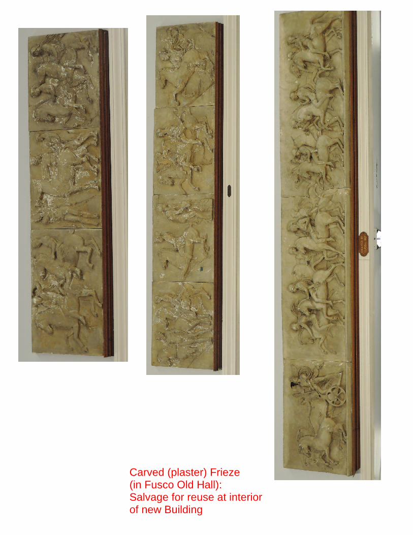
Carved (plaster) Frieze(in Fusco Old Hall): Salvage for reuse at interiorof new Building
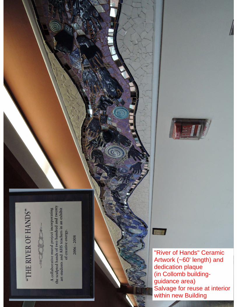
"River of Hands" CeramicArtwork (~60' length) anddedication plaque(in Collomb building-guidance area)Salvage for reuse at interiorwithin new Building

CLOCKWORKS: (in Collomb Building Clock Tower)Salvage for turn over to Owner
