arib std-t63-36.104 v8.12.0 evolved universal … universal terrestrial radio access (e-utra); base...
TRANSCRIPT
ARIB STD-T63-36.104 V8.12.0
Evolved Universal Terrestrial
Radio Access (E-UTRA);
Base Station (BS) radio
transmission and reception
(Release 8)
Refer to “Industrial Property Rights (IPR)” in the preface of ARIB STD-T63 for Related Industrial Property Rights. Refer to “Notice” in the preface of ARIB STD-T63 for Copyrights.
3GPP TS 36.104 V8.12.0 (2011-06) Technical Specification
3rd Generation Partnership Project; Technical Specification Group Radio Access Network; Evolved Universal Terrestrial Radio Access (E-UTRA);
Base Station (BS) radio transmission and reception (Release 8)
The present document has been developed within the 3rd Generation Partnership Project (3GPP TM) and may be further elaborated for the purposes of 3GPP.
The present document has not been subject to any approval process by the 3GPP Organizational Partners and shall not be implemented.
This Specification is provided for future development work within 3GPP only. The Organizational Partners accept no liability for any use of this Specification.
Specifications and reports for implementation of the 3GPP TM system should be obtained via the 3GPP Organizational Partners' Publications Offices.
3GPP
3GPP TS 36.104 V8.12.0 (2011-06) 2 Release 8
Keywords
UMTS, BSS, radio
3GPP
Postal address
3GPP support office address
650 Route des Lucioles - Sophia Antipolis Valbonne - FRANCE
Tel.: +33 4 92 94 42 00 Fax: +33 4 93 65 47 16
Internet
http://www.3gpp.org
Copyright Notification
No part may be reproduced except as authorized by written permission.
The copyright and the foregoing restriction extend to reproduction in all media.
© 2011, 3GPP Organizational Partners (ARIB, ATIS, CCSA, ETSI, TTA, TTC).
All rights reserved.
UMTS™ is a Trade Mark of ETSI registered for the benefit of its members
3GPP™ is a Trade Mark of ETSI registered for the benefit of its Members and of the 3GPP Organizational Partners
LTE™ is a Trade Mark of ETSI currently being registered for the benefit of its Members and of the 3GPP Organizational Partners
GSM® and the GSM logo are registered and owned by the GSM Association
3GPP
3GPP TS 36.104 V8.12.0 (2011-06) 3 Release 8
Contents
Foreword............................................................................................................................................................. 6
1 Scope ........................................................................................................................................................ 7
2 References ................................................................................................................................................ 7
3 Definitions, symbols and abbreviations ................................................................................................... 8 3.1 Definitions ......................................................................................................................................................... 8 3.2 Symbols ............................................................................................................................................................. 9 3.3 Abbreviations ..................................................................................................................................................... 9
4 General ................................................................................................................................................... 11 4.1 Relationship between minimum requirements and test requirements .............................................................. 11 4.2 Base station classes .......................................................................................................................................... 11 4.3 Regional requirements ..................................................................................................................................... 11
5 Operating bands and channel arrangement ............................................................................................ 13 5.1 General ............................................................................................................................................................. 13 5.2 Void ................................................................................................................................................................. 13 5.3 Void ................................................................................................................................................................. 13 5.4 Void ................................................................................................................................................................. 13 5.5 Operating bands ............................................................................................................................................... 13 5.6 Channel bandwidth .......................................................................................................................................... 13 5.7 Channel arrangement ....................................................................................................................................... 14 5.7.1 Channel spacing ......................................................................................................................................... 14 5.7.2 Channel raster............................................................................................................................................. 14 5.7.3 Carrier frequency and EARFCN ................................................................................................................ 15
6 Transmitter characteristics ..................................................................................................................... 16 6.1 General ............................................................................................................................................................. 16 6.2 Base station output power ................................................................................................................................ 16 6.2.1 Minimum requirement................................................................................................................................ 16 6.2.2 Additional requirement (regional) .............................................................................................................. 16 6.3 Output power dynamics ................................................................................................................................... 17 6.3.1 RE Power control dynamic range .............................................................................................................. 17 6.3.1.1 Minimum requirements ........................................................................................................................ 17 6.3.2 Total power dynamic range ........................................................................................................................ 17 6.3.2.1 Minimum requirements ........................................................................................................................ 17 6.4 Transmit ON/OFF power ................................................................................................................................. 18 6.4.1 Transmitter OFF power .............................................................................................................................. 18 6.4.1.1 Minimum Requirement......................................................................................................................... 18 6.4.2 Transmitter transient period ....................................................................................................................... 18 6.4.2.1 Minimum requirements ........................................................................................................................ 19 6.5 Transmitted signal quality ............................................................................................................................... 19 6.5.1 Frequency error .......................................................................................................................................... 19 6.5.1.1 Minimum requirement .......................................................................................................................... 19 6.5.2 Error Vector Magnitude ............................................................................................................................. 19 6.5.3 Time alignment between transmitter branches ........................................................................................... 19 6.5.3.1 Minimum Requirement......................................................................................................................... 20 6.5.4 DL RS power.............................................................................................................................................. 20 6.5.4.1 Minimum requirements ........................................................................................................................ 20 6.6 Unwanted emissions ........................................................................................................................................ 20 6.6.1 Occupied bandwidth ................................................................................................................................... 20 6.6.1.1 Minimum requirement .......................................................................................................................... 20 6.6.2 Adjacent Channel Leakage power Ratio (ACLR) ...................................................................................... 20 6.6.2.1 Minimum requirement .......................................................................................................................... 21 6.6.3 Operating band unwanted emissions .......................................................................................................... 21 6.6.3.1 Minimum requirements (Category A) .................................................................................................. 22 6.6.3.2 Minimum requirements (Category B) .................................................................................................. 24
3GPP
3GPP TS 36.104 V8.12.0 (2011-06) 4 Release 8
6.6.3.2.1 Category B requirements (Option 1) ............................................................................................... 24 6.6.3.2.2 Category B (Option 2) .......................................................................................................................... 26 6.6.3.3 Additional requirements ....................................................................................................................... 27 6.6.4 Transmitter spurious emissions .................................................................................................................. 28 6.6.4.1 Mandatory Requirements ..................................................................................................................... 29 6.6.4.1.1 Spurious emissions (Category A) ................................................................................................... 29 6.6.4.1.2 Spurious emissions (Category B) .................................................................................................... 29 6.6.4.2 Protection of the BS receiver of own or different BS ........................................................................... 29 6.6.4.2.1 Minimum Requirement ................................................................................................................... 30 6.6.4.3 Additional spurious emissions requirements ........................................................................................ 30 6.6.4.3.1 Minimum Requirement ................................................................................................................... 31 6.6.4.4 Co-location with other base stations ..................................................................................................... 33 6.6.4.4.1 Minimum Requirement ................................................................................................................... 34 6.7 Transmitter intermodulation ............................................................................................................................ 35 6.7.1 Minimum requirement................................................................................................................................ 35
7 Receiver characteristics .......................................................................................................................... 36 7.1 General ............................................................................................................................................................. 36 7.2 Reference sensitivity level ............................................................................................................................... 36 7.2.1 Minimum requirement................................................................................................................................ 37 7.3 Dynamic range ................................................................................................................................................. 37 7.3.1 Minimum requirement................................................................................................................................ 37 7.4 In-channel selectivity ....................................................................................................................................... 37 7.4.1 Minimum requirement................................................................................................................................ 38 7.5 Adjacent Channel Selectivity (ACS) and narrow-band blocking .................................................................... 38 7.5.1 Minimum requirement................................................................................................................................ 38 7.6 Blocking ........................................................................................................................................................... 39 7.6.1 General blocking requirement .................................................................................................................... 39 7.6.1.1 Minimum requirement .......................................................................................................................... 40 7.6.2 Co-location with other base stations .......................................................................................................... 40 7.6.2.1 Minimum requirement .......................................................................................................................... 41 7.7 Receiver spurious emissions ............................................................................................................................ 43 7.7.1 Minimum requirement................................................................................................................................ 43 7.8 Receiver intermodulation ................................................................................................................................. 43 7.8.1 Minimum requirement................................................................................................................................ 43
8 Performance requirement ....................................................................................................................... 44 8.1 General ............................................................................................................................................................. 44 8.2 Performance requirements for PUSCH ............................................................................................................ 45 8.2.1 Requirements in multipath fading propagation conditions ......................................................................... 45 8.2.1.1 Minimum requirements ........................................................................................................................ 45 8.2.2 Requirements for UL timing adjustment .................................................................................................... 51 8.2.2.1 Minimum requirements ........................................................................................................................ 52 8.2.3 Requirements for high speed train .............................................................................................................. 52 8.2.3.1 Minimum requirements ........................................................................................................................ 53 8.2.4 Requirements for HARQ-ACK multiplexed on PUSCH ........................................................................... 54 8.2.4.1 Minimum requirement ........................................................................................................................ 54 8.3 Performance requirements for PUCCH ........................................................................................................... 54 8.3.1 DTX to ACK performance ......................................................................................................................... 54 8.3.1.1 Minimum requirement ........................................................................................................................ 54 8.3.2 ACK missed detection requirements for single user PUCCH format 1a .................................................... 55 8.3.2.1 Minimum requirements ........................................................................................................................ 55 8.3.3 CQI performance requirements for PUCCH format 2 ................................................................................ 55 8.3.3.1 Minimum requirements ........................................................................................................................ 55 8.3.4 ACK missed detection requirements for multi user PUCCH format 1a ..................................................... 55 8.3.4.1 Minimum requirement ......................................................................................................................... 56 8.4 Performance requirements for PRACH ........................................................................................................... 56 8.4.1 PRACH False alarm probability................................................................................................................. 56 8.4.1.1 Minimum requirement .......................................................................................................................... 56 8.4.2 PRACH detection requirements ................................................................................................................. 56 8.4.2.1 Minimum requirements ........................................................................................................................ 56
3GPP
3GPP TS 36.104 V8.12.0 (2011-06) 5 Release 8
Annex A (normative): Reference measurement channels ............................................................... 58
A.1 Fixed Reference Channels for reference sensitivity and in-channel selectivity (QPSK, R=1/3) ........... 58
A.2 Fixed Reference Channels for dynamic range (16QAM, R=2/3) ........................................................... 59
A.3 Fixed Reference Channels for performance requirements (QPSK 1/3) ................................................. 59
A.4 Fixed Reference Channels for performance requirements (16QAM 3/4) .............................................. 60
A.5 Fixed Reference Channels for performance requirements (64QAM 5/6) .............................................. 60
A.6 PRACH Test preambles ......................................................................................................................... 60
A.7 Fixed Reference Channels for UL timing adjustment (Scenario 1) ....................................................... 61
A.8 Fixed Reference Channels for UL timing adjustment (Scenario 2) ....................................................... 61
A.9 Multi user PUCCH test .......................................................................................................................... 62
Annex B (normative): Propagation conditions ................................................................................. 63
B.1 Static propagation condition ................................................................................................................... 63
B.2 Multi-path fading propagation conditions .............................................................................................. 63
B.3 High speed train condition ..................................................................................................................... 64
B.4 Moving propagation conditions ............................................................................................................. 65
Annex C (normative): Characteristics of the interfering signals .................................................... 66
Annex D (normative): Environmental requirements for the BS equipment ................................. 67
Annex E (normative): Error Vector Magnitude .............................................................................. 68
E.1 Reference point for measurement........................................................................................................... 68
E.2 Basic unit of measurement ..................................................................................................................... 68
E.3 Modified signal under test ...................................................................................................................... 69
E.4 Estimation of frequency offset ............................................................................................................... 69
E.5 Estimation of time offset ........................................................................................................................ 69 E.5.1 Window length ................................................................................................................................................. 70
E.6 Estimation of TX chain amplitude and frequency response parameters ................................................ 70
E.7 Averaged EVM ...................................................................................................................................... 71
Annex F (Informative): Unwanted emission requirements for multi-carrier BS ............................. 73
F.1 General ................................................................................................................................................... 73
F.2 Multi-carrier BS of different E-UTRA channel bandwidths .................................................................. 73
F.3 Multi-carrier BS of E-UTRA and UTRA ............................................................................................... 73
Annex G (informative): Change history .............................................................................................. 74
3GPP
3GPP TS 36.104 V8.12.0 (2011-06) 6 Release 8
Foreword
This Technical Specification has been produced by the 3rd
Generation Partnership Project (3GPP).
The contents of the present document are subject to continuing work within the TSG and may change following formal
TSG approval. Should the TSG modify the contents of the present document, it will be re-released by the TSG with an
identifying change of release date and an increase in version number as follows:
Version x.y.z
where:
x the first digit:
1 presented to TSG for information;
2 presented to TSG for approval;
3 or greater indicates TSG approved document under change control.
y the second digit is incremented for all changes of substance, i.e. technical enhancements, corrections,
updates, etc.
z the third digit is incremented when editorial only changes have been incorporated in the document.
3GPP
3GPP TS 36.104 V8.12.0 (2011-06) 7 Release 8
1 Scope
The present document establishes the minimum RF characteristics and minimum performance requirements of E-UTRA
Base Station (BS).
2 References
The following documents contain provisions which, through reference in this text, constitute provisions of the present
document.
References are either specific (identified by date of publication, edition number, version number, etc.) or
non-specific.
For a specific reference, subsequent revisions do not apply.
For a non-specific reference, the latest version applies. In the case of a reference to a 3GPP document (including
a GSM document), a non-specific reference implicitly refers to the latest version of that document in the same
Release as the present document.
[1] 3GPP TR 21.905: "Vocabulary for 3GPP Specifications".
[2] ITU-R Recommendation SM.329: "Unwanted emissions in the spurious domain".
[3] ITU-R Recommendation M.1545: "Measurement uncertainty as it applies to test limits for the
terrestrial component of International Mobile Telecommunications-2000".
[4] 3GPP TS 36.141: "Evolved Universal Terrestrial Radio Access (E-UTRA); Base Station (BS)
conformance testing".
[5] ITU-R recommendation SM.328: "Spectra and bandwidth of emissions".
[6] 3GPP TS 25.104: "Base Station (BS) radio transmission and reception (FDD)".
[7] 3GPP TS 25.105: "Base Station (BS) radio transmission and reception (TDD)".
[8] 3GPP TR 25.942: "RF system scenarios".
[9] 3GPP TR 36.942: "E-UTRA RF system scenarios".
[10] 3GPP TS 36.211: "Evolved Universal Terrestrial Radio Access (E-UTRA); Physical Channels and
Modulation".
[11] 3GPP TS 36.213: "Evolved Universal Terrestrial Radio Access (E-UTRA); Physical layer
procedures".
[12] IEC 60721-3-3 (2002): "Classification of environmental conditions - Part 3: Classification of
groups of environmental parameters and their severities - Section 3: Stationary use at weather
protected locations".
[13] IEC 60721-3-4 (1995): "Classification of environmental conditions - Part 3: Classification of
groups of environmental parameters and their severities - Section 4: Stationary use at non-weather
protected locations".
3GPP
3GPP TS 36.104 V8.12.0 (2011-06) 8 Release 8
3 Definitions, symbols and abbreviations
3.1 Definitions
For the purposes of the present document, the terms and definitions given in TR 21.905 [1] and the following apply. A
term defined in the present document takes precedence over the definition of the same term, if any, in TR 21.905 [1].
Base station receive period: The time during which the base station is receiving data subframes or UpPTS.
Carrier: The modulated waveform conveying the E-UTRA or UTRA physical channels
Channel bandwidth: The RF bandwidth supporting a single E-UTRA RF carrier with the transmission bandwidth
configured in the uplink or downlink of a cell. The channel bandwidth is measured in MHz and is used as a reference
for transmitter and receiver RF requirements.
Channel edge: The lowest and highest frequency of the E-UTRA carrier, separated by the channel bandwidth.
DL RS power: The resource element power of Downlink Reference Symbol.
Downlink operating band: The part of the operating band designated for downlink.
Maximum output Power: The mean power level per carrier of the base station measured at the antenna connector in a
specified reference condition.
Maximum throughput: The maximum achievable throughput for a reference measurement channel.
Mean power: When applied to E-UTRA transmission this is the power measured in the channel bandwidth of the
carrier. The period of measurement shall be at least one subframe (1ms), unless otherwise stated.
Measurement bandwidth: The bandwidth in which an emission level is specified.
Multi-carrier transmission configuration: A set of one or more contiguous carriers that a BS is able to transmit
simultaneously according to the manufacturer’s specification.
Occupied bandwidth: The width of a frequency band such that, below the lower and above the upper frequency limits,
the mean powers emitted are each equal to a specified percentage β/2 of the total mean power of a given emission.
Operating band: A frequency range in which E-UTRA operates (paired or unpaired), that is defined with a specific set
of technical requirements.
NOTE: The operating band(s) for an E-UTRA BS is declared by the manufacturer according to the designations
in table 5.5-1.
Output power: The mean power of one carrier of the base station, delivered to a load with resistance equal to the
nominal load impedance of the transmitter.
Rated output power: Rated output power of the base station is the mean power level per carrier that the manufacturer
has declared to be available at the antenna connector during the transmitter ON period.
RE power control dynamic range: The difference between the power of a RE and the average RE power for a BS at
maximum output power for a specified reference condition.
RRC filtered mean power: The mean power of a UTRA carrier as measured through a root raised cosine filter with
roll-off factor and a bandwidth equal to the chip rate of the radio access mode.
NOTE 1: The RRC filtered mean power of a perfectly modulated UTRA signal is 0.246 dB lower than the mean
power of the same signal.
Throughput: The number of payload bits successfully received per second for a reference measurement channel in a
specified reference condition.
Total power dynamic range: The difference between the maximum and the minimum transmit power of an OFDM
symbol for a specified reference condition.
3GPP
3GPP TS 36.104 V8.12.0 (2011-06) 9 Release 8
Transmission bandwidth: Bandwidth of an instantaneous transmission from a UE or BS, measured in Resource Block
units.
Transmission bandwidth configuration: The highest transmission bandwidth allowed for uplink or downlink in a
given channel bandwidth, measured in Resource Block units.
Transmitter ON period: The time period during which the BS transmitter is transmitting data and/or reference
symbols, i.e. data subframes or DwPTS.
Transmitter OFF period: The time period during which the BS transmitter is not allowed to transmit.
Transmitter transient period: The time period during which the transmitter is changing from the OFF period to the
ON period or vice versa.
Uplink operating band: The part of the operating band designated for uplink.
3.2 Symbols
For the purposes of the present document, the following symbols apply:
Roll-off factor
Percentage of the mean transmitted power emitted outside the occupied bandwidth on the assigned
channel
BWChannel Channel bandwidth
BWConfig Transmission bandwidth configuration, expressed in MHz, where BWConfig = NRB x 180 kHz in the
uplink and BWConfig = 15 kHz + NRB x 180 kHz in the downlink.
f Frequency
f Separation between the channel edge frequency and the nominal -3dB point of the measuring filter
closest to the carrier frequency
fmax The largest value of f used for defining the requirement
FC Carrier centre frequency
f_offset Separation between the channel edge frequency and the centre of the measuring filter
f_offsetmax The maximum value of f_offset used for defining the requirement
FDL_low The lowest frequency of the downlink operating band
FDL_high The highest frequency of the downlink operating band
FUL_low The lowest frequency of the uplink operating band
FUL_high The highest frequency of the uplink operating band
NDL Downlink EARFCN
NOffs-DL Offset used for calculating downlink EARFCN
NOffs-UL Offset used for calculating uplink EARFCN
NCS Number of Cyclic shifts for preamble generation in PRACH
NRB Transmission bandwidth configuration, expressed in units of resource blocks
NUL Uplink EARFCN
Pmax Maximum output Power
Pout Output power
PREFSENS Reference Sensitivity power level
TA Timing advance command, as defined in [11]
sT Basic time unit, as defined in [10]
3.3 Abbreviations
For the purposes of the present document, the abbreviations given in TR 21.905 [1] and the following apply. An
abbreviation defined in the present document takes precedence over the definition of the same abbreviation, if any, in
TR 21.905 [1].
ACLR Adjacent Channel Leakage Ratio
ACK Acknowledgement (in HARQ protocols)
ACS Adjacent Channel Selectivity
3GPP
3GPP TS 36.104 V8.12.0 (2011-06) 10 Release 8
AWGN Additive White Gaussian Noise
BS Base Station
CP Cyclic prefix
CRC Cyclic Redundancy Check
CW Continuous Wave
DC Direct Current
DFT Discrete Fourier Transformation
DTX Discontinuous Transmission
DwPTS Downlink part of the special subframe (for TDD operation)
EARFCN E-UTRA Absolute Radio Frequency Channel Number
EPA Extended Pedestrian A model
ETU Extended Typical Urban model
E-UTRA Evolved UTRA
EVA Extended Vehicular A model
EVM Error Vector Magnitude
FDD Frequency Division Duplex
FFT Fast Fourier Transformation
FRC Fixed Reference Channel
GP Guard Period (for TDD operation)
HARQ Hybrid Automatic Repeat Request
ICS In-Channel Selectivity
ITU-R Radiocommunication Sector of the ITU
LNA Low Noise Amplifier
MCS Modulation and Coding Scheme
OFDM Orthogonal Frequency Division Multiplex
OOB Out-of-band
PA Power Amplifier
PBCH Physical Broadcast Channel
PDCCH Physical Downlink Control Channel
PDSCH Physical Downlink Shared Channel
PUSCH Physical Uplink Shared Channel
PUCCH Physical Uplink Control Channel
PRACH Physical Random Access Channel
QAM Quadrature Amplitude Modulation
QPSK Quadrature Phase-Shift Keying
RB Resource Block
RE Resource Element
RF Radio Frequency
RMS Root Mean Square (value)
RS Reference Symbol
RX Receiver
RRC Root Raised Cosine
SNR Signal-to-Noise Ratio
TA Timing Advance
TDD Time Division Duplex
TX Transmitter
UE User Equipment
3GPP
3GPP TS 36.104 V8.12.0 (2011-06) 11 Release 8
4 General
4.1 Relationship between minimum requirements and test requirements
The Minimum Requirements given in this specification make no allowance for measurement uncertainty. The test
specification TS 36.141 [4] Annex G defines Test Tolerances. These Test Tolerances are individually calculated for
each test. The Test Tolerances are used to relax the Minimum Requirements in this specification to create Test
Requirements.
The measurement results returned by the Test System are compared - without any modification - against the Test
Requirements as defined by the shared risk principle.
The Shared Risk principle is defined in ITU-R M.1545 [3].
4.2 Base station classes
The requirements in this specification apply to Base Stations intended for general-purpose applications.
Other base station classes are for further study. The requirements for these may be different than for general-purpose
applications.
4.3 Regional requirements
Some requirements in the present document may only apply in certain regions either as optional requirements or set by
local and regional regulation as mandatory requirements. It is normally not stated in the 3GPP specifications under what
exact circumstances that the requirements apply, since this is defined by local or regional regulation.
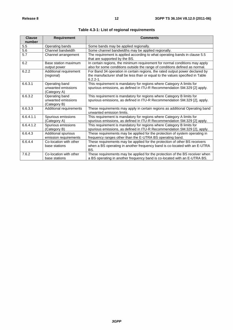
Table 4.3-1 lists all requirements that may be applied differently in different regions.
3GPP
3GPP TS 36.104 V8.12.0 (2011-06) 12 Release 8
Table 4.3-1: List of regional requirements
Clause number
Requirement Comments
5.5 Operating bands Some bands may be applied regionally.
5.6 Channel bandwidth Some channel bandwidths may be applied regionally.
5.7 Channel arrangement The requirement is applied according to what operating bands in clause 5.5 that are supported by the BS.
6.2 Base station maximum output power
In certain regions, the minimum requirement for normal conditions may apply also for some conditions outside the range of conditions defined as normal.
6.2.2 Additional requirement (regional)
For Band 34 operation in certain regions, the rated output power declared by the manufacturer shall be less than or equal to the values specified in Table 6.2.2-1.
6.6.3.1 Operating band unwanted emissions (Category A)
This requirement is mandatory for regions where Category A limits for spurious emissions, as defined in ITU-R Recommendation SM.329 [2] apply.
6.6.3.2 Operating band unwanted emissions (Category B)
This requirement is mandatory for regions where Category B limits for spurious emissions, as defined in ITU-R Recommendation SM.329 [2], apply.
6.6.3.3 Additional requirements These requirements may apply in certain regions as additional Operating band unwanted emission limits.
6.6.4.1.1 Spurious emissions (Category A)
This requirement is mandatory for regions where Category A limits for spurious emissions, as defined in ITU-R Recommendation SM.329 [2] apply.
6.6.4.1.2 Spurious emissions (Category B)
This requirement is mandatory for regions where Category B limits for spurious emissions, as defined in ITU-R Recommendation SM.329 [2], apply.
6.6.4.3 Additional spurious emission requirements
These requirements may be applied for the protection of system operating in frequency ranges other than the E-UTRA BS operating band.
6.6.4.4 Co-location with other base stations
These requirements may be applied for the protection of other BS receivers when a BS operating in another frequency band is co-located with an E-UTRA BS.
7.6.2 Co-location with other base stations
These requirements may be applied for the protection of the BS receiver when a BS operating in another frequency band is co-located with an E-UTRA BS.
3GPP
3GPP TS 36.104 V8.12.0 (2011-06) 13 Release 8
5 Operating bands and channel arrangement
5.1 General
The channel arrangements presented in this clause are based on the operating bands and channel bandwidths defined in
the present release of specifications.
NOTE: Other operating bands and channel bandwidths may be considered in future releases.
5.2 Void
5.3 Void
5.4 Void
5.5 Operating bands
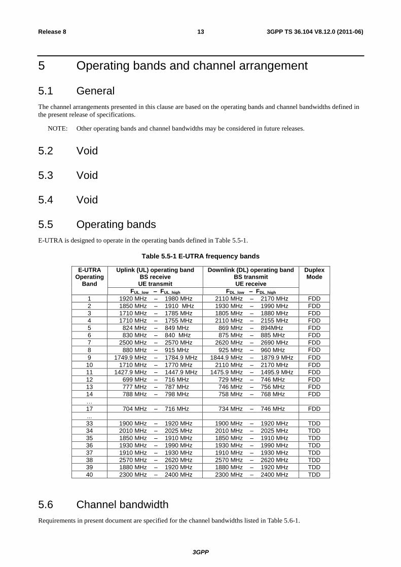
E-UTRA is designed to operate in the operating bands defined in Table 5.5-1.
Table 5.5-1 E-UTRA frequency bands
E-UTRA Operating
Band
Uplink (UL) operating band BS receive UE transmit
Downlink (DL) operating band BS transmit UE receive
Duplex Mode
FUL_low – FUL_high FDL_low – FDL_high
1 1920 MHz – 1980 MHz 2110 MHz – 2170 MHz FDD
2 1850 MHz – 1910 MHz 1930 MHz – 1990 MHz FDD
3 1710 MHz – 1785 MHz 1805 MHz – 1880 MHz FDD
4 1710 MHz – 1755 MHz 2110 MHz – 2155 MHz FDD
5 824 MHz – 849 MHz 869 MHz – 894MHz FDD
6 830 MHz – 840 MHz 875 MHz – 885 MHz FDD
7 2500 MHz – 2570 MHz 2620 MHz – 2690 MHz FDD
8 880 MHz – 915 MHz 925 MHz – 960 MHz FDD
9 1749.9 MHz – 1784.9 MHz 1844.9 MHz – 1879.9 MHz FDD
10 1710 MHz – 1770 MHz 2110 MHz – 2170 MHz FDD
11 1427.9 MHz – 1447.9 MHz 1475.9 MHz – 1495.9 MHz FDD
12 699 MHz – 716 MHz 729 MHz – 746 MHz FDD
13 777 MHz – 787 MHz 746 MHz – 756 MHz FDD
14 788 MHz – 798 MHz 758 MHz – 768 MHz FDD
…
17 704 MHz – 716 MHz 734 MHz – 746 MHz FDD
...
33 1900 MHz – 1920 MHz 1900 MHz – 1920 MHz TDD
34 2010 MHz – 2025 MHz 2010 MHz – 2025 MHz TDD
35 1850 MHz – 1910 MHz 1850 MHz – 1910 MHz TDD
36 1930 MHz – 1990 MHz 1930 MHz – 1990 MHz TDD
37 1910 MHz – 1930 MHz 1910 MHz – 1930 MHz TDD
38 2570 MHz – 2620 MHz 2570 MHz – 2620 MHz TDD
39 1880 MHz – 1920 MHz 1880 MHz – 1920 MHz TDD
40 2300 MHz – 2400 MHz 2300 MHz – 2400 MHz TDD
5.6 Channel bandwidth
Requirements in present document are specified for the channel bandwidths listed in Table 5.6-1.
3GPP
3GPP TS 36.104 V8.12.0 (2011-06) 14 Release 8
Table 5.6-1 Transmission bandwidth configuration NRB in E-UTRA channel bandwidths
Channel bandwidth BWChannel [MHz]
1.4 3 5 10 15 20
Transmission bandwidth configuration NRB
6 15 25 50 75 100
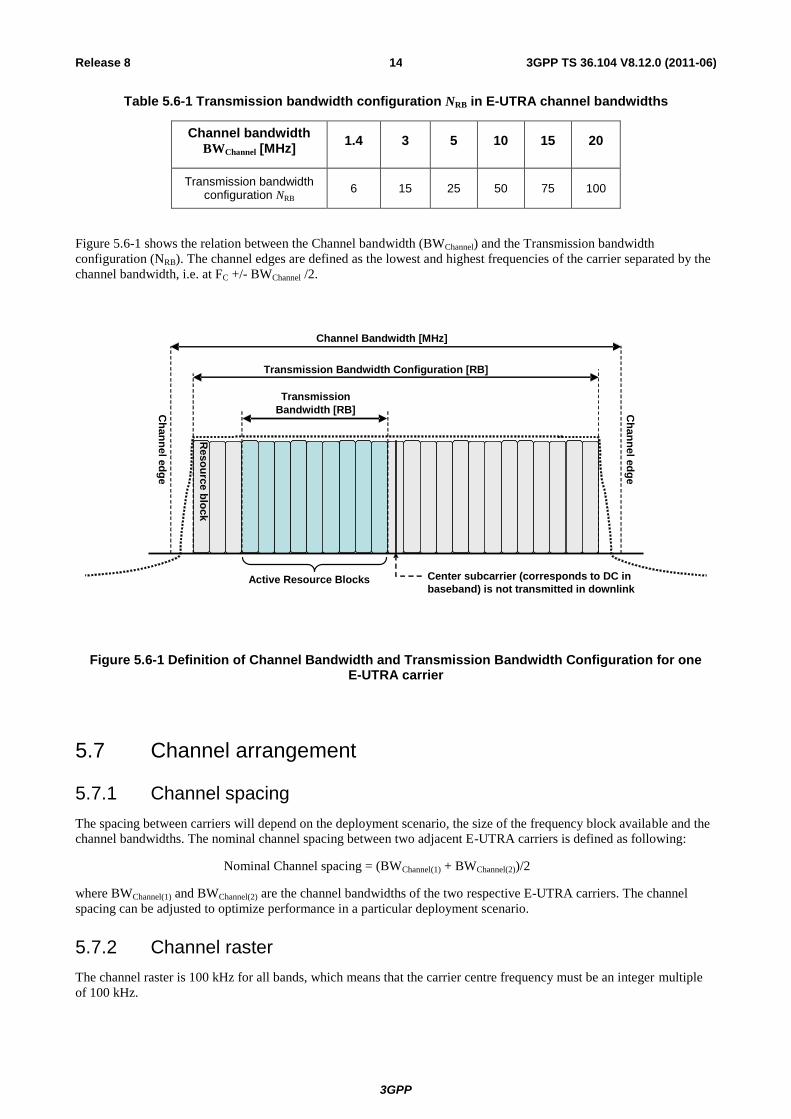
Figure 5.6-1 shows the relation between the Channel bandwidth (BWChannel) and the Transmission bandwidth
configuration (NRB). The channel edges are defined as the lowest and highest frequencies of the carrier separated by the
channel bandwidth, i.e. at FC +/- BWChannel /2.
Figure 5.6-1 Definition of Channel Bandwidth and Transmission Bandwidth Configuration for one E-UTRA carrier
5.7 Channel arrangement
5.7.1 Channel spacing
The spacing between carriers will depend on the deployment scenario, the size of the frequency block available and the
channel bandwidths. The nominal channel spacing between two adjacent E-UTRA carriers is defined as following:
Nominal Channel spacing = (BWChannel(1) + BWChannel(2))/2
where BWChannel(1) and BWChannel(2) are the channel bandwidths of the two respective E-UTRA carriers. The channel
spacing can be adjusted to optimize performance in a particular deployment scenario.
5.7.2 Channel raster
The channel raster is 100 kHz for all bands, which means that the carrier centre frequency must be an integer multiple
of 100 kHz.
Transmission Bandwidth [RB]
Transmission Bandwidth Configuration [RB]
Channel Bandwidth [MHz]
Center subcarrier (corresponds to DC in
baseband) is not transmitted in downlink Active Resource Blocks
Ch
an
nel e
dg
e
Ch
an
nel e
dg
e
Reso
urc
e b
loc
k
3GPP
3GPP TS 36.104 V8.12.0 (2011-06) 15 Release 8
5.7.3 Carrier frequency and EARFCN
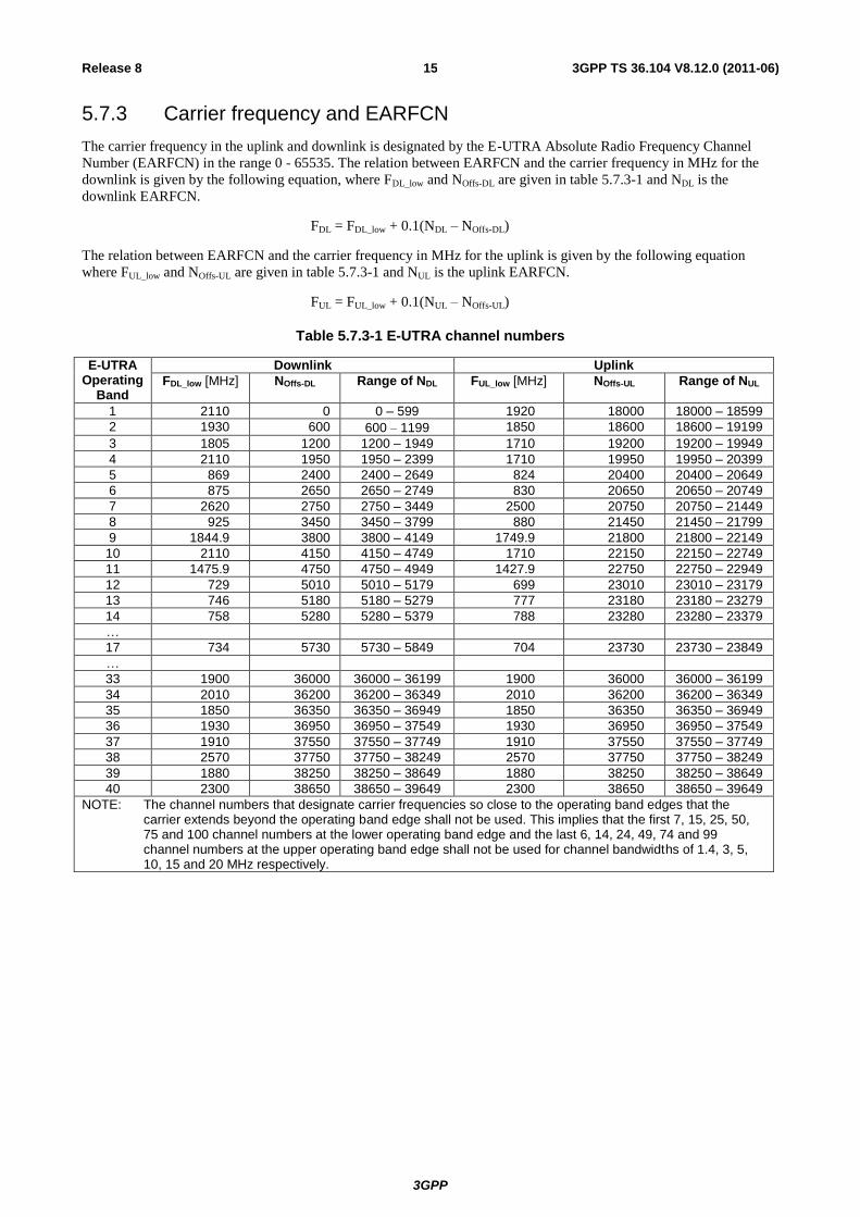
The carrier frequency in the uplink and downlink is designated by the E-UTRA Absolute Radio Frequency Channel
Number (EARFCN) in the range 0 - 65535. The relation between EARFCN and the carrier frequency in MHz for the
downlink is given by the following equation, where FDL_low and NOffs-DL are given in table 5.7.3-1 and NDL is the
downlink EARFCN.
FDL = FDL_low + 0.1(NDL – NOffs-DL)
The relation between EARFCN and the carrier frequency in MHz for the uplink is given by the following equation
where FUL_low and NOffs-UL are given in table 5.7.3-1 and NUL is the uplink EARFCN.
FUL = FUL_low + 0.1(NUL – NOffs-UL)
Table 5.7.3-1 E-UTRA channel numbers
E-UTRA Operating
Band
Downlink Uplink
FDL_low [MHz] NOffs-DL Range of NDL FUL_low [MHz] NOffs-UL Range of NUL
1 2110 0 0 – 599 1920 18000 18000 – 18599
2 1930 600 600 1199 1850 18600 18600 – 19199
3 1805 1200 1200 – 1949 1710 19200 19200 – 19949
4 2110 1950 1950 – 2399 1710 19950 19950 – 20399
5 869 2400 2400 – 2649 824 20400 20400 – 20649
6 875 2650 2650 – 2749 830 20650 20650 – 20749
7 2620 2750 2750 – 3449 2500 20750 20750 – 21449
8 925 3450 3450 – 3799 880 21450 21450 – 21799
9 1844.9 3800 3800 – 4149 1749.9 21800 21800 – 22149
10 2110 4150 4150 – 4749 1710 22150 22150 – 22749
11 1475.9 4750 4750 – 4949 1427.9 22750 22750 – 22949
12 729 5010 5010 – 5179 699 23010 23010 – 23179
13 746 5180 5180 – 5279 777 23180 23180 – 23279
14 758 5280 5280 – 5379 788 23280 23280 – 23379
…
17 734 5730 5730 – 5849 704 23730 23730 – 23849
…
33 1900 36000 36000 – 36199 1900 36000 36000 – 36199
34 2010 36200 36200 – 36349 2010 36200 36200 – 36349
35 1850 36350 36350 – 36949 1850 36350 36350 – 36949
36 1930 36950 36950 – 37549 1930 36950 36950 – 37549
37 1910 37550 37550 – 37749 1910 37550 37550 – 37749
38 2570 37750 37750 – 38249 2570 37750 37750 – 38249
39 1880 38250 38250 – 38649 1880 38250 38250 – 38649
40 2300 38650 38650 – 39649 2300 38650 38650 – 39649
NOTE: The channel numbers that designate carrier frequencies so close to the operating band edges that the carrier extends beyond the operating band edge shall not be used. This implies that the first 7, 15, 25, 50, 75 and 100 channel numbers at the lower operating band edge and the last 6, 14, 24, 49, 74 and 99 channel numbers at the upper operating band edge shall not be used for channel bandwidths of 1.4, 3, 5, 10, 15 and 20 MHz respectively.
3GPP
3GPP TS 36.104 V8.12.0 (2011-06) 16 Release 8
6 Transmitter characteristics
6.1 General
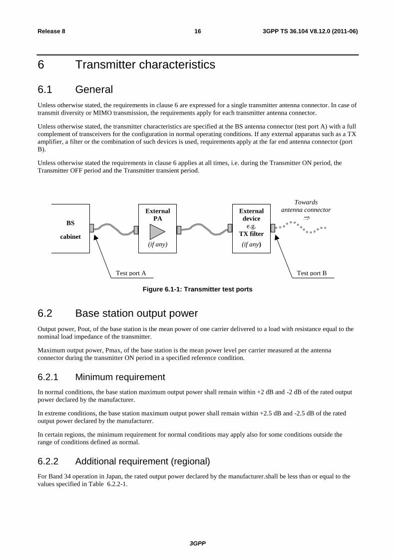
Unless otherwise stated, the requirements in clause 6 are expressed for a single transmitter antenna connector. In case of
transmit diversity or MIMO transmission, the requirements apply for each transmitter antenna connector.
Unless otherwise stated, the transmitter characteristics are specified at the BS antenna connector (test port A) with a full
complement of transceivers for the configuration in normal operating conditions. If any external apparatus such as a TX
amplifier, a filter or the combination of such devices is used, requirements apply at the far end antenna connector (port
B).
Unless otherwise stated the requirements in clause 6 applies at all times, i.e. during the Transmitter ON period, the
Transmitter OFF period and the Transmitter transient period.
BS
cabinet
Test port A Test port B
External
device
e.g.
TX filter
(if any)
External
PA
(if any)
Towards
antenna connector
Figure 6.1-1: Transmitter test ports
6.2 Base station output power
Output power, Pout, of the base station is the mean power of one carrier delivered to a load with resistance equal to the
nominal load impedance of the transmitter.
Maximum output power, Pmax, of the base station is the mean power level per carrier measured at the antenna
connector during the transmitter ON period in a specified reference condition.
6.2.1 Minimum requirement
In normal conditions, the base station maximum output power shall remain within +2 dB and -2 dB of the rated output
power declared by the manufacturer.
In extreme conditions, the base station maximum output power shall remain within +2.5 dB and -2.5 dB of the rated
output power declared by the manufacturer.
In certain regions, the minimum requirement for normal conditions may apply also for some conditions outside the
range of conditions defined as normal.
6.2.2 Additional requirement (regional)
For Band 34 operation in Japan, the rated output power declared by the manufacturer.shall be less than or equal to the
values specified in Table 6.2.2-1.
3GPP
3GPP TS 36.104 V8.12.0 (2011-06) 17 Release 8
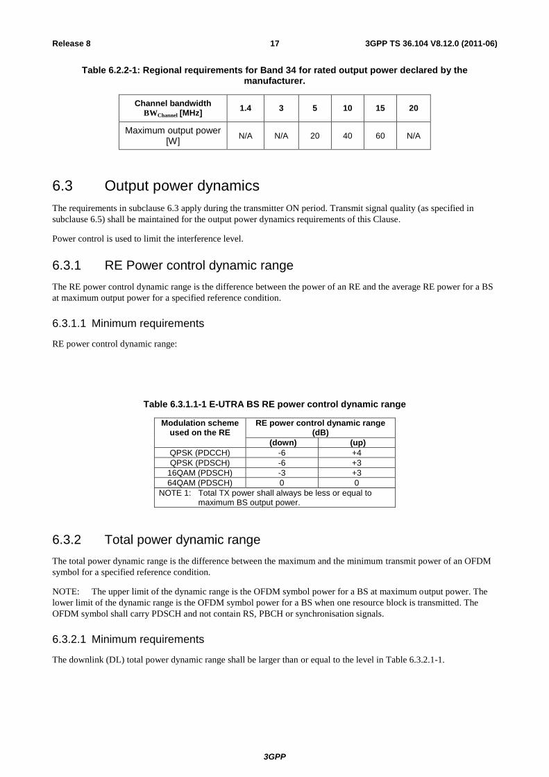
Table 6.2.2-1: Regional requirements for Band 34 for rated output power declared by the manufacturer.
Channel bandwidth BWChannel [MHz]
1.4 3 5 10 15 20
Maximum output power [W]
N/A N/A 20 40 60 N/A
6.3 Output power dynamics
The requirements in subclause 6.3 apply during the transmitter ON period. Transmit signal quality (as specified in
subclause 6.5) shall be maintained for the output power dynamics requirements of this Clause.
Power control is used to limit the interference level.
6.3.1 RE Power control dynamic range
The RE power control dynamic range is the difference between the power of an RE and the average RE power for a BS
at maximum output power for a specified reference condition.
6.3.1.1 Minimum requirements
RE power control dynamic range:
Table 6.3.1.1-1 E-UTRA BS RE power control dynamic range
Modulation scheme used on the RE
RE power control dynamic range (dB)
(down) (up)
QPSK (PDCCH) -6 +4
QPSK (PDSCH) -6 +3
16QAM (PDSCH) -3 +3
64QAM (PDSCH) 0 0
NOTE 1: Total TX power shall always be less or equal to maximum BS output power.
6.3.2 Total power dynamic range
The total power dynamic range is the difference between the maximum and the minimum transmit power of an OFDM
symbol for a specified reference condition.
NOTE: The upper limit of the dynamic range is the OFDM symbol power for a BS at maximum output power. The
lower limit of the dynamic range is the OFDM symbol power for a BS when one resource block is transmitted. The
OFDM symbol shall carry PDSCH and not contain RS, PBCH or synchronisation signals.
6.3.2.1 Minimum requirements
The downlink (DL) total power dynamic range shall be larger than or equal to the level in Table 6.3.2.1-1.
3GPP
3GPP TS 36.104 V8.12.0 (2011-06) 18 Release 8
Table 6.3.2.1-1 E-UTRA BS total power dynamic range
E-UTRA channel bandwidth (MHz)
Total power dynamic range (dB)
1.4 7.7
3 11.7
5 13.9
10 16.9
15 18.7
20 20
6.4 Transmit ON/OFF power
The requirements in subclause 6.4 are only applied for E-UTRA TDD BS.
6.4.1 Transmitter OFF power
Transmitter OFF power is defined as the mean power measured over 70 us filtered with a square filter of bandwidth
equal to the transmission bandwidth configuration of the BS (BWConfig) centred on the assigned channel frequency
during the transmitter OFF period.
6.4.1.1 Minimum Requirement
The transmitter OFF power spectral density shall be less than -85dBm/MHz.
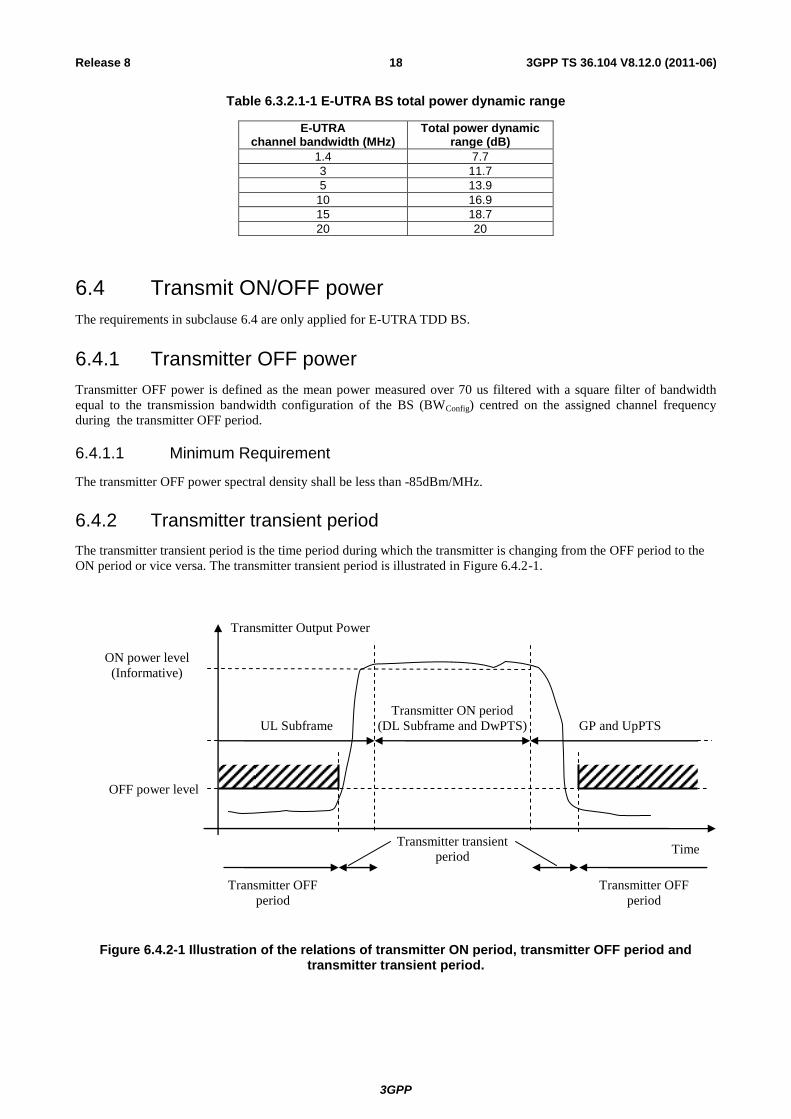
6.4.2 Transmitter transient period
The transmitter transient period is the time period during which the transmitter is changing from the OFF period to the
ON period or vice versa. The transmitter transient period is illustrated in Figure 6.4.2-1.
Figure 6.4.2-1 Illustration of the relations of transmitter ON period, transmitter OFF period and transmitter transient period.
Transmitter Output Power
Time
Transmitter ON period
(DL Subframe and DwPTS)
Transmitter OFF
period
Transmitter OFF
period
Transmitter transient
period
OFF power level
ON power level
(Informative)
UL Subframe
GP and UpPTS
3GPP
3GPP TS 36.104 V8.12.0 (2011-06) 19 Release 8
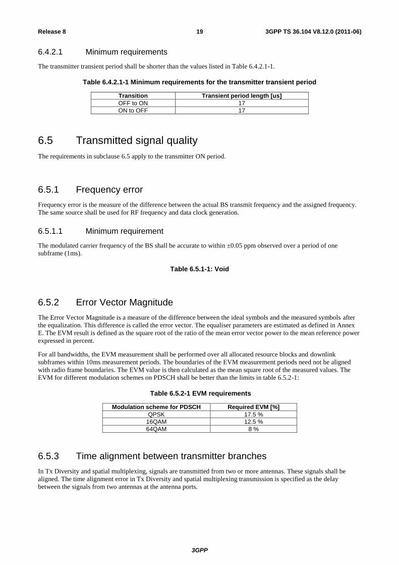
6.4.2.1 Minimum requirements
The transmitter transient period shall be shorter than the values listed in Table 6.4.2.1-1.
Table 6.4.2.1-1 Minimum requirements for the transmitter transient period
Transition Transient period length [us]
OFF to ON 17
ON to OFF 17
6.5 Transmitted signal quality
The requirements in subclause 6.5 apply to the transmitter ON period.
6.5.1 Frequency error
Frequency error is the measure of the difference between the actual BS transmit frequency and the assigned frequency.
The same source shall be used for RF frequency and data clock generation.
6.5.1.1 Minimum requirement
The modulated carrier frequency of the BS shall be accurate to within ±0.05 ppm observed over a period of one
subframe (1ms).
Table 6.5.1-1: Void
6.5.2 Error Vector Magnitude
The Error Vector Magnitude is a measure of the difference between the ideal symbols and the measured symbols after
the equalization. This difference is called the error vector. The equaliser parameters are estimated as defined in Annex
E. The EVM result is defined as the square root of the ratio of the mean error vector power to the mean reference power
expressed in percent.
For all bandwidths, the EVM measurement shall be performed over all allocated resource blocks and downlink
subframes within 10ms measurement periods. The boundaries of the EVM measurement periods need not be aligned
with radio frame boundaries. The EVM value is then calculated as the mean square root of the measured values. The
EVM for different modulation schemes on PDSCH shall be better than the limits in table 6.5.2-1:
Table 6.5.2-1 EVM requirements
Modulation scheme for PDSCH Required EVM [%]
QPSK 17.5 %
16QAM 12.5 %
64QAM 8 %
6.5.3 Time alignment between transmitter branches
In Tx Diversity and spatial multiplexing, signals are transmitted from two or more antennas. These signals shall be
aligned. The time alignment error in Tx Diversity and spatial multiplexing transmission is specified as the delay
between the signals from two antennas at the antenna ports.
3GPP
3GPP TS 36.104 V8.12.0 (2011-06) 20 Release 8
6.5.3.1 Minimum Requirement
The time alignment error in Tx Diversity or spatial multiplexing for any possible configuration of two transmit antennas
shall not exceed 65 ns.
6.5.4 DL RS power
DL RS power is the resource element power of the Downlink Reference Symbol.
The absolute DL RS power is indicated on the DL-SCH. The absolute accuracy is defined as the maximum deviation
between the DL RS power indicated on the DL-SCH and the DL RS power at the BS antenna connector.
6.5.4.1 Minimum requirements
DL RS power shall be within 2.1 dB of the DL RS power indicated on the DL-SCH
6.6 Unwanted emissions
Unwanted emissions consist of out-of-band emissions and spurious emissions [2]. Out of band emissions are unwanted
emissions immediately outside the channel bandwidth resulting from the modulation process and non-linearity in the
transmitter but excluding spurious emissions. Spurious emissions are emissions which are caused by unwanted
transmitter effects such as harmonics emission, parasitic emission, intermodulation products and frequency conversion
products, but exclude out of band emissions.
The out-of-band emissions requirement for the BS transmitter is specified both in terms of Adjacent Channel Leakage
power Ratio (ACLR) and Operating band unwanted emissions. The Operating band unwanted emissions define all
unwanted emissions in the downlink operating band plus the frequency ranges 10 MHz above and 10 MHz below the
band. Unwanted emissions outside of this frequency range are limited by a spurious emissions requirement.
There is in addition a requirement for occupied bandwidth.
6.6.1 Occupied bandwidth
The occupied bandwidth is the width of a frequency band such that, below the lower and above the upper frequency
limits, the mean powers emitted are each equal to a specified percentage /2 of the total mean transmitted power. See
also ITU-R Recommendation SM.328 [5].
The value of /2 shall be taken as 0.5%.
The requirement applies during the transmitter ON period.
6.6.1.1 Minimum requirement
The occupied bandwidth shall be less than the channel bandwidth as defined in Table 5.6-1.
6.6.2 Adjacent Channel Leakage power Ratio (ACLR)
Adjacent Channel Leakage power Ratio (ACLR) is the ratio of the filtered mean power centred on the assigned channel
frequency to the filtered mean power centred on an adjacent channel frequency.
The requirements shall apply whatever the type of transmitter considered (single carrier or multi-carrier). It applies for
all transmission modes foreseen by the manufacturer's specification. For a multi-carrier BS, the requirement applies for
the adjacent channel frequencies below the lowest carrier frequency transmitted by the BS and above the highest carrier
frequency transmitted by the BS for each supported multi-carrier transmission configuration. The requirement applies
during the transmitter ON period.
3GPP
3GPP TS 36.104 V8.12.0 (2011-06) 21 Release 8
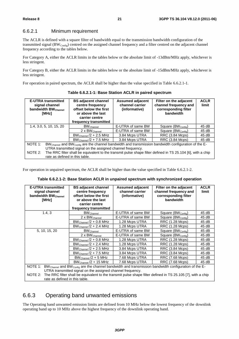
6.6.2.1 Minimum requirement
The ACLR is defined with a square filter of bandwidth equal to the transmission bandwidth configuration of the
transmitted signal (BWConfig) centred on the assigned channel frequency and a filter centred on the adjacent channel
frequency according to the tables below.
For Category A, either the ACLR limits in the tables below or the absolute limit of -13dBm/MHz apply, whichever is
less stringent.
For Category B, either the ACLR limits in the tables below or the absolute limit of -15dBm/MHz apply, whichever is
less stringent.
For operation in paired spectrum, the ACLR shall be higher than the value specified in Table 6.6.2.1-1.
Table 6.6.2.1-1: Base Station ACLR in paired spectrum
E-UTRA transmitted signal channel
bandwidth BWChannel [MHz]
BS adjacent channel centre frequency
offset below the first or above the last
carrier centre frequency transmitted
Assumed adjacent channel carrier
(informative)
Filter on the adjacent channel frequency and
corresponding filter bandwidth
ACLR limit
1.4, 3.0, 5, 10, 15, 20 BWChannel E-UTRA of same BW Square (BWConfig) 45 dB
2 x BWChannel E-UTRA of same BW Square (BWConfig) 45 dB
BWChannel /2 + 2.5 MHz 3.84 Mcps UTRA RRC (3.84 Mcps) 45 dB
BWChannel /2 + 7.5 MHz 3.84 Mcps UTRA RRC (3.84 Mcps) 45 dB
NOTE 1: BWChannel and BWConfig are the channel bandwidth and transmission bandwidth configuration of the E-UTRA transmitted signal on the assigned channel frequency.
NOTE 2: The RRC filter shall be equivalent to the transmit pulse shape filter defined in TS 25.104 [6], with a chip rate as defined in this table.
For operation in unpaired spectrum, the ACLR shall be higher than the value specified in Table 6.6.2.1-2.
Table 6.6.2.1-2: Base Station ACLR in unpaired spectrum with synchronized operation
E-UTRA transmitted signal channel
bandwidth BWChannel [MHz]
BS adjacent channel centre frequency
offset below the first or above the last
carrier centre frequency transmitted
Assumed adjacent channel carrier
(informative)
Filter on the adjacent channel frequency and
corresponding filter bandwidth
ACLR limit
1.4, 3 BWChannel E-UTRA of same BW Square (BWConfig) 45 dB
2 x BWChannel E-UTRA of same BW Square (BWConfig) 45 dB
BWChannel /2 + 0.8 MHz 1.28 Mcps UTRA RRC (1.28 Mcps) 45 dB
BWChannel /2 + 2.4 MHz 1.28 Mcps UTRA RRC (1.28 Mcps) 45 dB
5, 10, 15, 20 BWChannel E-UTRA of same BW Square (BWConfig) 45 dB
2 x BWChannel E-UTRA of same BW Square (BWConfig) 45 dB
BWChannel /2 + 0.8 MHz 1.28 Mcps UTRA RRC (1.28 Mcps) 45 dB
BWChannel /2 + 2.4 MHz 1.28 Mcps UTRA RRC (1.28 Mcps) 45 dB
BWChannel /2 + 2.5 MHz 3.84 Mcps UTRA RRC (3.84 Mcps) 45 dB
BWChannel /2 + 7.5 MHz 3.84 Mcps UTRA RRC (3.84 Mcps) 45 dB
BWChannel /2 + 5 MHz 7.68 Mcps UTRA RRC (7.68 Mcps) 45 dB
BWChannel /2 + 15 MHz 7.68 Mcps UTRA RRC (7.68 Mcps) 45 dB
NOTE 1: BWChannel and BWConfig are the channel bandwidth and transmission bandwidth configuration of the E-UTRA transmitted signal on the assigned channel frequency.
NOTE 2: The RRC filter shall be equivalent to the transmit pulse shape filter defined in TS 25.105 [7], with a chip rate as defined in this table.
6.6.3 Operating band unwanted emissions
The Operating band unwanted emission limits are defined from 10 MHz below the lowest frequency of the downlink
operating band up to 10 MHz above the highest frequency of the downlink operating band.
3GPP
3GPP TS 36.104 V8.12.0 (2011-06) 22 Release 8
The requirements shall apply whatever the type of transmitter considered (single carrier or multi-carrier) and for all
transmission modes foreseen by the manufacturer's specification.
The unwanted emission limits in the part of the downlink operating band that falls in the spurious domain are consistent
with ITU-R Recommendation SM.329 [2].
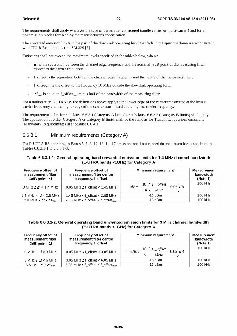
Emissions shall not exceed the maximum levels specified in the tables below, where:
- f is the separation between the channel edge frequency and the nominal -3dB point of the measuring filter
closest to the carrier frequency.
- f_offset is the separation between the channel edge frequency and the centre of the measuring filter.
- f_offsetmax is the offset to the frequency 10 MHz outside the downlink operating band.
- fmax is equal to f_offsetmax minus half of the bandwidth of the measuring filter.
For a multicarrier E-UTRA BS the definitions above apply to the lower edge of the carrier transmitted at the lowest
carrier frequency and the higher edge of the carrier transmitted at the highest carrier frequency.
The requirements of either subclause 6.6.3.1 (Category A limits) or subclause 6.6.3.2 (Category B limits) shall apply.
The application of either Category A or Category B limits shall be the same as for Transmitter spurious emissions
(Mandatory Requirements) in subclause 6.6.4.1.
6.6.3.1 Minimum requirements (Category A)
For E-UTRA BS operating in Bands 5, 6, 8, 12, 13, 14, 17 emissions shall not exceed the maximum levels specified in
Tables 6.6.3.1-1 to 6.6.3.1-3.
Table 6.6.3.1-1: General operating band unwanted emission limits for 1.4 MHz channel bandwidth (E-UTRA bands <1GHz) for Category A
Frequency offset of measurement filter
-3dB point, f
Frequency offset of measurement filter centre
frequency, f_offset
Minimum requirement Measurement bandwidth
(Note 1)
0 MHz f < 1.4 MHz 0.05 MHz f_offset < 1.45 MHz dBMHz
offsetfdBm 05.0
_
4.1
101
100 kHz
1.4 MHz f < 2.8 MHz 1.45 MHz f_offset < 2.85 MHz -11 dBm 100 kHz
2.8 MHz f fmax 2.85 MHz f_offset < f_offsetmax -13 dBm 100 kHz
Table 6.6.3.1-2: General operating band unwanted emission limits for 3 MHz channel bandwidth (E-UTRA bands <1GHz) for Category A
Frequency offset of measurement filter
-3dB point, f
Frequency offset of measurement filter centre
frequency, f_offset
Minimum requirement Measurement bandwidth
(Note 1)
0 MHz f < 3 MHz 0.05 MHz f_offset < 3.05 MHz dBMHz
offsetfdBm 05.0
_
3
105
100 kHz
3 MHz f < 6 MHz 3.05 MHz f_offset < 6.05 MHz -15 dBm 100 kHz
6 MHz f fmax 6.05 MHz f_offset < f_offsetmax -13 dBm 100 kHz
3GPP
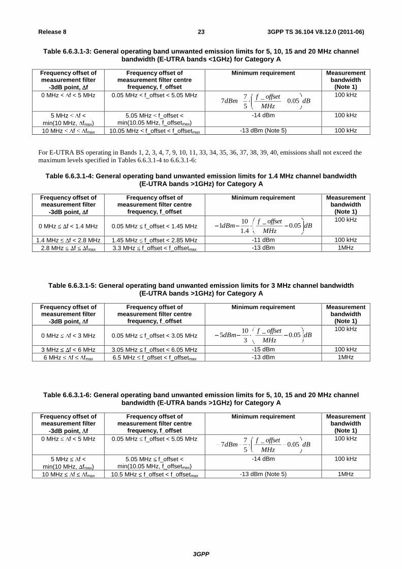
3GPP TS 36.104 V8.12.0 (2011-06) 23 Release 8
Table 6.6.3.1-3: General operating band unwanted emission limits for 5, 10, 15 and 20 MHz channel bandwidth (E-UTRA bands <1GHz) for Category A
Frequency offset of measurement filter
-3dB point, f
Frequency offset of measurement filter centre
frequency, f_offset
Minimum requirement Measurement bandwidth
(Note 1)
0 MHz f < 5 MHz 0.05 MHz f_offset < 5.05 MHz dB
MHz
offsetfdBm 05.0
_
5
77
100 kHz
5 MHz f <
min(10 MHz, fmax)
5.05 MHz f_offset < min(10.05 MHz, f_offsetmax)
-14 dBm 100 kHz
10 MHz f fmax 10.05 MHz f_offset < f_offsetmax -13 dBm (Note 5) 100 kHz
For E-UTRA BS operating in Bands 1, 2, 3, 4, 7, 9, 10, 11, 33, 34, 35, 36, 37, 38, 39, 40, emissions shall not exceed the
maximum levels specified in Tables 6.6.3.1-4 to 6.6.3.1-6:
Table 6.6.3.1-4: General operating band unwanted emission limits for 1.4 MHz channel bandwidth (E-UTRA bands >1GHz) for Category A
Frequency offset of measurement filter
-3dB point, f
Frequency offset of measurement filter centre
frequency, f_offset
Minimum requirement Measurement bandwidth
(Note 1)
0 MHz f < 1.4 MHz 0.05 MHz f_offset < 1.45 MHz dBMHz
offsetfdBm 05.0
_
4.1
101
100 kHz
1.4 MHz f < 2.8 MHz 1.45 MHz f_offset < 2.85 MHz -11 dBm 100 kHz
2.8 MHz f fmax 3.3 MHz f_offset < f_offsetmax -13 dBm 1MHz
Table 6.6.3.1-5: General operating band unwanted emission limits for 3 MHz channel bandwidth (E-UTRA bands >1GHz) for Category A
Frequency offset of measurement filter
-3dB point, f
Frequency offset of measurement filter centre
frequency, f_offset
Minimum requirement Measurement bandwidth
(Note 1)
0 MHz f < 3 MHz 0.05 MHz f_offset < 3.05 MHz dBMHz
offsetfdBm 05.0
_
3
105
100 kHz
3 MHz f < 6 MHz 3.05 MHz f_offset < 6.05 MHz -15 dBm 100 kHz
6 MHz f fmax 6.5 MHz f_offset < f_offsetmax -13 dBm 1MHz
Table 6.6.3.1-6: General operating band unwanted emission limits for 5, 10, 15 and 20 MHz channel bandwidth (E-UTRA bands >1GHz) for Category A
Frequency offset of measurement filter
-3dB point, f
Frequency offset of measurement filter centre
frequency, f_offset
Minimum requirement Measurement bandwidth
(Note 1)
0 MHz f < 5 MHz 0.05 MHz f_offset < 5.05 MHz dB
MHz
offsetfdBm 05.0
_
5
77
100 kHz
5 MHz f <
min(10 MHz, fmax)
5.05 MHz f_offset < min(10.05 MHz, f_offsetmax)
-14 dBm 100 kHz
10 MHz f fmax 10.5 MHz f_offset < f_offsetmax -13 dBm (Note 5) 1MHz
3GPP
3GPP TS 36.104 V8.12.0 (2011-06) 24 Release 8
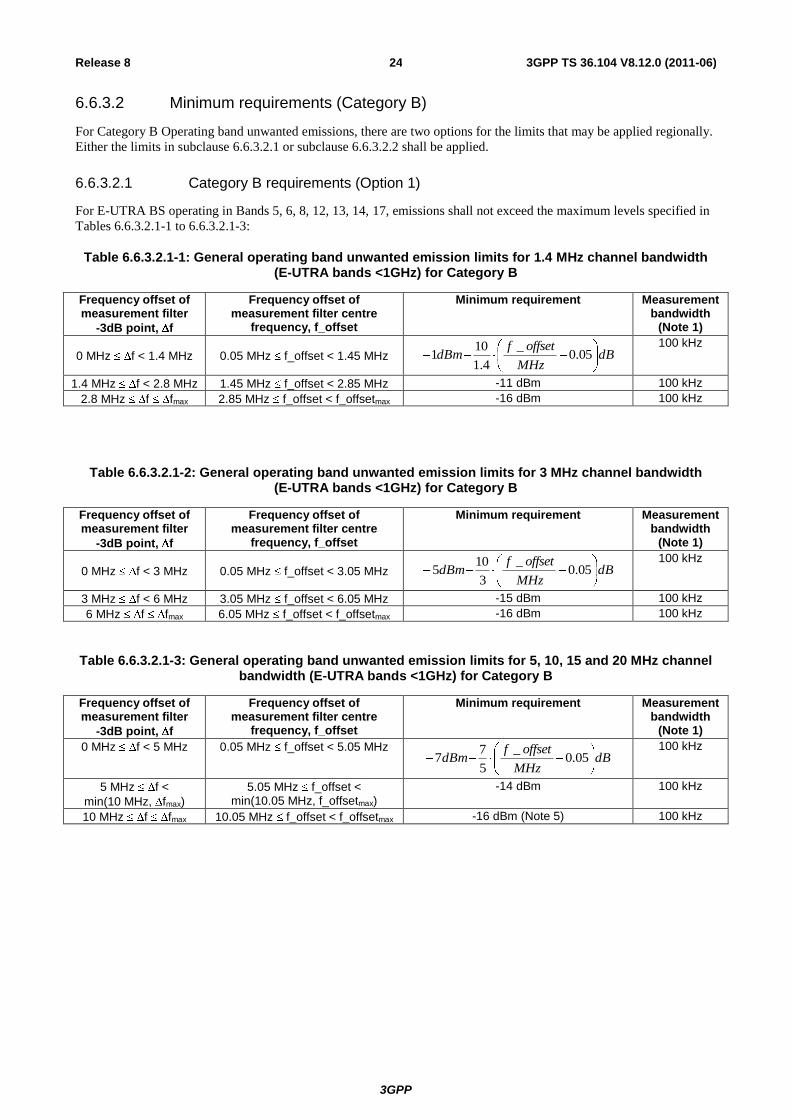
6.6.3.2 Minimum requirements (Category B)
For Category B Operating band unwanted emissions, there are two options for the limits that may be applied regionally.
Either the limits in subclause 6.6.3.2.1 or subclause 6.6.3.2.2 shall be applied.
6.6.3.2.1 Category B requirements (Option 1)
For E-UTRA BS operating in Bands 5, 6, 8, 12, 13, 14, 17, emissions shall not exceed the maximum levels specified in
Tables 6.6.3.2.1-1 to 6.6.3.2.1-3:
Table 6.6.3.2.1-1: General operating band unwanted emission limits for 1.4 MHz channel bandwidth (E-UTRA bands <1GHz) for Category B
Frequency offset of measurement filter
-3dB point, f
Frequency offset of measurement filter centre
frequency, f_offset
Minimum requirement Measurement bandwidth
(Note 1)
0 MHz f < 1.4 MHz 0.05 MHz f_offset < 1.45 MHz dBMHz
offsetfdBm 05.0
_
4.1
101
100 kHz
1.4 MHz f < 2.8 MHz 1.45 MHz f_offset < 2.85 MHz -11 dBm 100 kHz
2.8 MHz f fmax 2.85 MHz f_offset < f_offsetmax -16 dBm 100 kHz
Table 6.6.3.2.1-2: General operating band unwanted emission limits for 3 MHz channel bandwidth (E-UTRA bands <1GHz) for Category B
Frequency offset of measurement filter
-3dB point, f
Frequency offset of measurement filter centre
frequency, f_offset
Minimum requirement Measurement bandwidth
(Note 1)
0 MHz f < 3 MHz 0.05 MHz f_offset < 3.05 MHz dBMHz
offsetfdBm 05.0
_
3
105
100 kHz
3 MHz f < 6 MHz 3.05 MHz f_offset < 6.05 MHz -15 dBm 100 kHz
6 MHz f fmax 6.05 MHz f_offset < f_offsetmax -16 dBm 100 kHz
Table 6.6.3.2.1-3: General operating band unwanted emission limits for 5, 10, 15 and 20 MHz channel bandwidth (E-UTRA bands <1GHz) for Category B
Frequency offset of measurement filter
-3dB point, f
Frequency offset of measurement filter centre
frequency, f_offset
Minimum requirement Measurement bandwidth
(Note 1)
0 MHz f < 5 MHz 0.05 MHz f_offset < 5.05 MHz dB
MHz
offsetfdBm 05.0
_
5
77
100 kHz
5 MHz f <
min(10 MHz, fmax)
5.05 MHz f_offset < min(10.05 MHz, f_offsetmax)
-14 dBm 100 kHz
10 MHz f fmax 10.05 MHz f_offset < f_offsetmax -16 dBm (Note 5) 100 kHz
3GPP
3GPP TS 36.104 V8.12.0 (2011-06) 25 Release 8
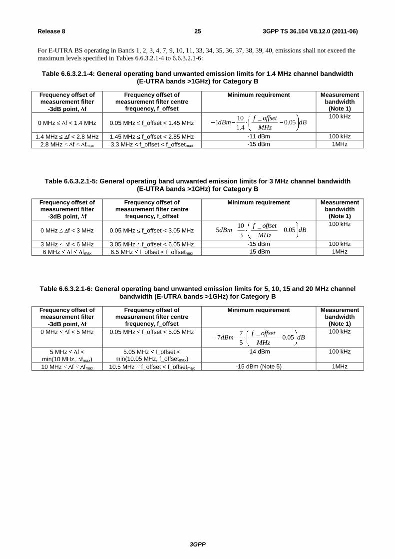
For E-UTRA BS operating in Bands 1, 2, 3, 4, 7, 9, 10, 11, 33, 34, 35, 36, 37, 38, 39, 40, emissions shall not exceed the
maximum levels specified in Tables 6.6.3.2.1-4 to 6.6.3.2.1-6:
Table 6.6.3.2.1-4: General operating band unwanted emission limits for 1.4 MHz channel bandwidth (E-UTRA bands >1GHz) for Category B
Frequency offset of measurement filter
-3dB point, f
Frequency offset of measurement filter centre
frequency, f_offset
Minimum requirement Measurement bandwidth
(Note 1)
0 MHz f < 1.4 MHz 0.05 MHz f_offset < 1.45 MHz dBMHz
offsetfdBm 05.0
_
4.1
101
100 kHz
1.4 MHz f < 2.8 MHz 1.45 MHz f_offset < 2.85 MHz -11 dBm 100 kHz
2.8 MHz f fmax 3.3 MHz f_offset < f_offsetmax -15 dBm 1MHz
Table 6.6.3.2.1-5: General operating band unwanted emission limits for 3 MHz channel bandwidth (E-UTRA bands >1GHz) for Category B
Frequency offset of measurement filter
-3dB point, f
Frequency offset of measurement filter centre
frequency, f_offset
Minimum requirement Measurement bandwidth
(Note 1)
0 MHz f < 3 MHz 0.05 MHz f_offset < 3.05 MHz dBMHz
offsetfdBm 05.0
_
3
105
100 kHz
3 MHz f < 6 MHz 3.05 MHz f_offset < 6.05 MHz -15 dBm 100 kHz
6 MHz f fmax 6.5 MHz f_offset < f_offsetmax -15 dBm 1MHz
Table 6.6.3.2.1-6: General operating band unwanted emission limits for 5, 10, 15 and 20 MHz channel bandwidth (E-UTRA bands >1GHz) for Category B
Frequency offset of measurement filter
-3dB point, f
Frequency offset of measurement filter centre
frequency, f_offset
Minimum requirement Measurement bandwidth
(Note 1)
0 MHz f < 5 MHz 0.05 MHz f_offset < 5.05 MHz dB
MHz
offsetfdBm 05.0
_
5
77
100 kHz
5 MHz f <
min(10 MHz, fmax)
5.05 MHz f_offset < min(10.05 MHz, f_offsetmax)
-14 dBm 100 kHz
10 MHz f fmax 10.5 MHz f_offset < f_offsetmax -15 dBm (Note 5) 1MHz
3GPP
3GPP TS 36.104 V8.12.0 (2011-06) 26 Release 8
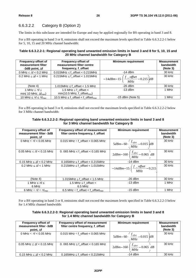
6.6.3.2.2 Category B (Option 2)
The limits in this subclause are intended for Europe and may be applied regionally for BS operating in band 3 and 8.
For a BS operating in band 3 or 8, emissions shall not exceed the maximum levels specified in Table 6.6.3.2.2-1 below
for 5, 10, 15 and 20 MHz channel bandwidth:
Table 6.6.3.2.2-1: Regional operating band unwanted emission limits in band 3 and 8 for 5, 10, 15 and 20 MHz channel bandwidth for Category B
Frequency offset of measurement filter
-3dB point, f
Frequency offset of measurement filter centre
frequency, f_offset
Minimum requirement Measurement bandwidth
(Note 3)
0 MHz f < 0.2 MHz 0.015MHz f_offset < 0.215MHz -14 dBm 30 kHz
0.2 MHz f < 1 MHz 0.215MHz f_offset < 1.015MHz dB
MHz
offsetfdBm 215.0
_1514
30 kHz
(Note 4) 1.015MHz f_offset < 1.5 MHz -26 dBm 30 kHz
1 MHz f
min( 10 MHz, fmax)
1.5 MHz f_offset < min(10.5 MHz, f_offsetmax)
-13 dBm 1 MHz
10 MHz f fmax 10.5 MHz f_offset < f_offsetmax -15 dBm (Note 5) 1 MHz
For a BS operating in band 3 or 8, emissions shall not exceed the maximum levels specified in Table 6.6.3.2.2-2 below
for 3 MHz channel bandwidth:
Table 6.6.3.2.2-2: Regional operating band unwanted emission limits in band 3 and 8 for 3 MHz channel bandwidth for Category B
Frequency offset of measurement filter -3dB
point, f
Frequency offset of measurement filter centre frequency, f_offset
Minimum requirement Measurement bandwidth
(Note 3)
0 MHz f < 0.05 MHz 0.015 MHz f_offset < 0.065 MHz dB
MHz
fdBm
offset015.0605
30 kHz
0.05 MHz f < 0.15 MHz 0. 065 MHz f_offset < 0.165 MHz dB
MHz
fdBm
offset065.01602
30 kHz
0.15 MHz f < 0.2 MHz 0.165MHz f_offset < 0.215MHz -14 dBm 30 kHz
0.2 MHz f < 1 MHz 0.215MHz f_offset < 1.015MHz dB
MHz
offsetfdBm 215.0
_1514
30 kHz
(Note 4) 1.015MHz f_offset < 1.5 MHz -26 dBm 30 kHz
1 MHz f 6 MHz
1.5 MHz f_offset < 6.5 MHz
-13 dBm 1 MHz
6 MHz f fmax 6.5 MHz f_offset < f_offsetmax -15 dBm 1 MHz
For a BS operating in band 3 or 8, emissions shall not exceed the maximum levels specified in Table 6.6.3.2.2-3 below
for 1.4 MHz channel bandwidth:
Table 6.6.3.2.2-3: Regional operating band unwanted emission limits in band 3 and 8 for 1.4 MHz channel bandwidth for Category B
Frequency offset of measurement filter -3dB
point, f
Frequency offset of measurement filter centre frequency, f_offset
Minimum requirement Measurement bandwidth
(Note 3)
0 MHz f < 0.05 MHz 0.015 MHz f_offset < 0.065 MHz dB
MHz
fdBm
offset015.0605
30 kHz
0.05 MHz f < 0.15 MHz 0. 065 MHz f_offset < 0.165 MHz dB
MHz
fdBm
offset065.01602
30 kHz
0.15 MHz f < 0.2 MHz 0.165MHz f_offset < 0.215MHz -14 dBm 30 kHz
3GPP
3GPP TS 36.104 V8.12.0 (2011-06) 27 Release 8
0.2 MHz f < 1 MHz 0.215MHz f_offset < 1.015MHz dB
MHz
offsetfdBm 215.0
_1514
30 kHz
(Note 4) 1.015MHz f_offset < 1.5 MHz -26 dBm 30 kHz
1 MHz f 2.8 MHz 1.5 MHz f_offset < 3.3 MHz -13 dBm 1 MHz
2.8 MHz f fmax 3.3 MHz f_offset < f_offsetmax -15 dBm 1 MHz
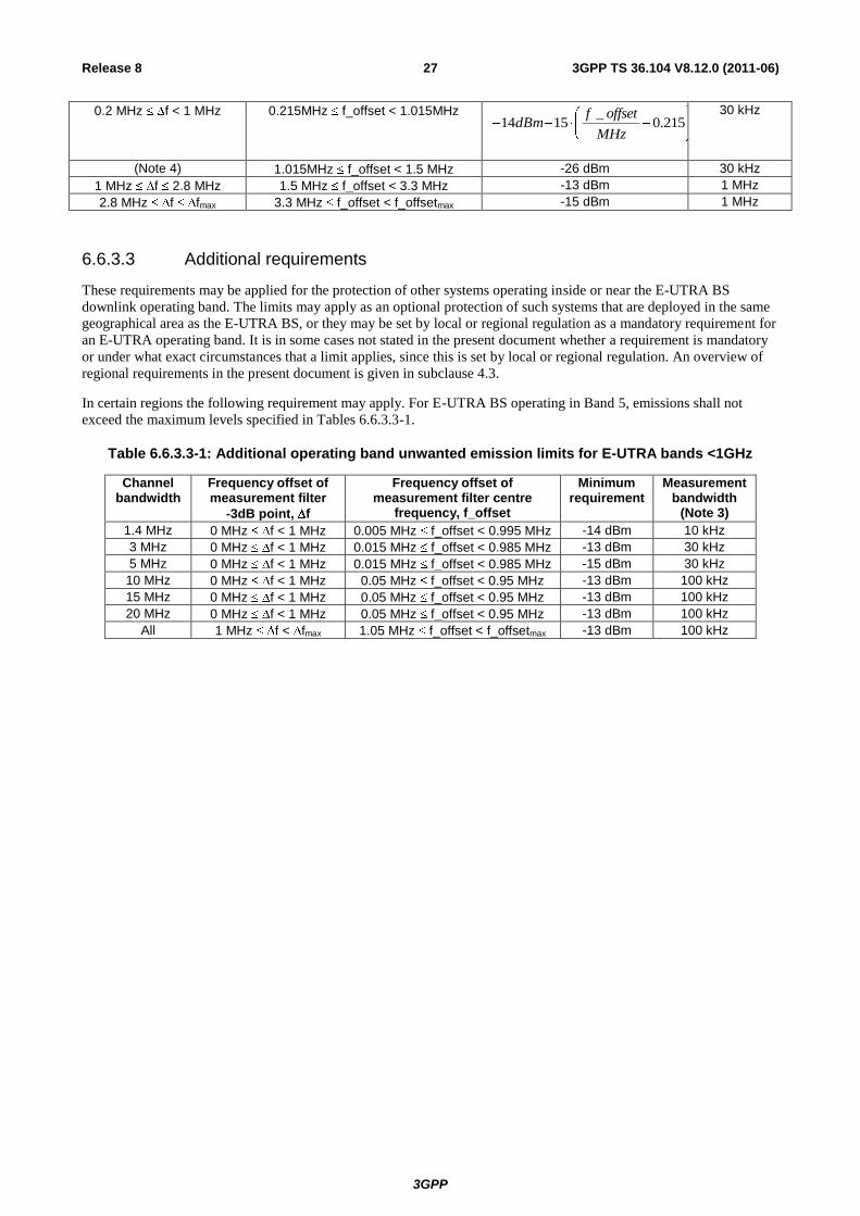
6.6.3.3 Additional requirements
These requirements may be applied for the protection of other systems operating inside or near the E-UTRA BS
downlink operating band. The limits may apply as an optional protection of such systems that are deployed in the same
geographical area as the E-UTRA BS, or they may be set by local or regional regulation as a mandatory requirement for
an E-UTRA operating band. It is in some cases not stated in the present document whether a requirement is mandatory
or under what exact circumstances that a limit applies, since this is set by local or regional regulation. An overview of
regional requirements in the present document is given in subclause 4.3.
In certain regions the following requirement may apply. For E-UTRA BS operating in Band 5, emissions shall not
exceed the maximum levels specified in Tables 6.6.3.3-1.
Table 6.6.3.3-1: Additional operating band unwanted emission limits for E-UTRA bands <1GHz
Channel bandwidth
Frequency offset of measurement filter
-3dB point, f
Frequency offset of measurement filter centre
frequency, f_offset
Minimum requirement
Measurement bandwidth
(Note 3)
1.4 MHz 0 MHz f < 1 MHz 0.005 MHz f_offset < 0.995 MHz -14 dBm 10 kHz
3 MHz 0 MHz f < 1 MHz 0.015 MHz f_offset < 0.985 MHz -13 dBm 30 kHz
5 MHz 0 MHz f < 1 MHz 0.015 MHz f_offset < 0.985 MHz -15 dBm 30 kHz
10 MHz 0 MHz f < 1 MHz 0.05 MHz f_offset < 0.95 MHz -13 dBm 100 kHz
15 MHz 0 MHz f < 1 MHz 0.05 MHz f_offset < 0.95 MHz -13 dBm 100 kHz
20 MHz 0 MHz f < 1 MHz 0.05 MHz f_offset < 0.95 MHz -13 dBm 100 kHz
All 1 MHz f < fmax 1.05 MHz f_offset < f_offsetmax -13 dBm 100 kHz
3GPP
3GPP TS 36.104 V8.12.0 (2011-06) 28 Release 8
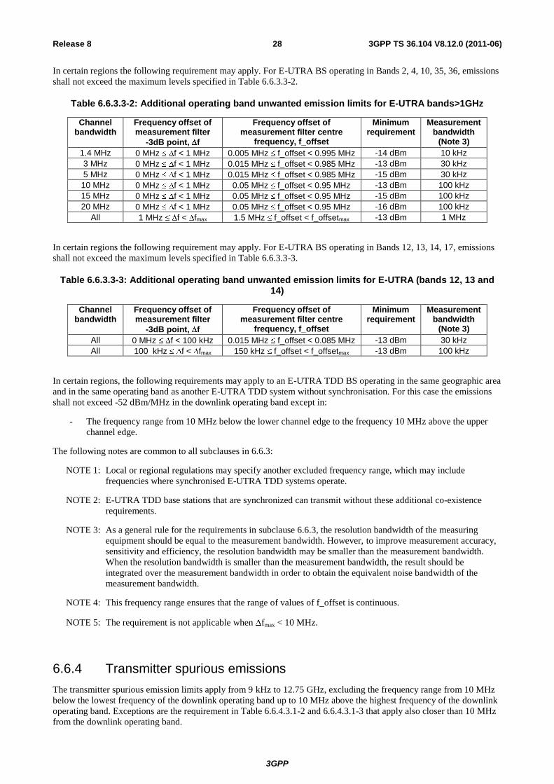
In certain regions the following requirement may apply. For E-UTRA BS operating in Bands 2, 4, 10, 35, 36, emissions
shall not exceed the maximum levels specified in Table 6.6.3.3-2.
Table 6.6.3.3-2: Additional operating band unwanted emission limits for E-UTRA bands>1GHz
Channel bandwidth
Frequency offset of measurement filter
-3dB point, f
Frequency offset of measurement filter centre
frequency, f_offset
Minimum requirement
Measurement bandwidth
(Note 3)
1.4 MHz 0 MHz f < 1 MHz 0.005 MHz f_offset < 0.995 MHz -14 dBm 10 kHz
3 MHz 0 MHz f < 1 MHz 0.015 MHz f_offset < 0.985 MHz -13 dBm 30 kHz
5 MHz 0 MHz f < 1 MHz 0.015 MHz f_offset < 0.985 MHz -15 dBm 30 kHz
10 MHz 0 MHz f < 1 MHz 0.05 MHz f_offset < 0.95 MHz -13 dBm 100 kHz
15 MHz 0 MHz f < 1 MHz 0.05 MHz f_offset < 0.95 MHz -15 dBm 100 kHz
20 MHz 0 MHz f < 1 MHz 0.05 MHz f_offset < 0.95 MHz -16 dBm 100 kHz
All 1 MHz f < fmax 1.5 MHz f_offset < f_offsetmax -13 dBm 1 MHz
In certain regions the following requirement may apply. For E-UTRA BS operating in Bands 12, 13, 14, 17, emissions
shall not exceed the maximum levels specified in Table 6.6.3.3-3.
Table 6.6.3.3-3: Additional operating band unwanted emission limits for E-UTRA (bands 12, 13 and 14)
Channel bandwidth
Frequency offset of measurement filter
-3dB point, f
Frequency offset of measurement filter centre
frequency, f_offset
Minimum requirement
Measurement bandwidth
(Note 3)
All 0 MHz f < 100 kHz 0.015 MHz f_offset < 0.085 MHz -13 dBm 30 kHz
All 100 kHz f < fmax 150 kHz f_offset < f_offsetmax -13 dBm 100 kHz
In certain regions, the following requirements may apply to an E-UTRA TDD BS operating in the same geographic area
and in the same operating band as another E-UTRA TDD system without synchronisation. For this case the emissions
shall not exceed -52 dBm/MHz in the downlink operating band except in:
- The frequency range from 10 MHz below the lower channel edge to the frequency 10 MHz above the upper
channel edge.
The following notes are common to all subclauses in 6.6.3:
NOTE 1: Local or regional regulations may specify another excluded frequency range, which may include
frequencies where synchronised E-UTRA TDD systems operate.
NOTE 2: E-UTRA TDD base stations that are synchronized can transmit without these additional co-existence
requirements.
NOTE 3: As a general rule for the requirements in subclause 6.6.3, the resolution bandwidth of the measuring
equipment should be equal to the measurement bandwidth. However, to improve measurement accuracy,
sensitivity and efficiency, the resolution bandwidth may be smaller than the measurement bandwidth.
When the resolution bandwidth is smaller than the measurement bandwidth, the result should be
integrated over the measurement bandwidth in order to obtain the equivalent noise bandwidth of the
measurement bandwidth.
NOTE 4: This frequency range ensures that the range of values of f_offset is continuous.
NOTE 5: The requirement is not applicable when fmax < 10 MHz.
6.6.4 Transmitter spurious emissions
The transmitter spurious emission limits apply from 9 kHz to 12.75 GHz, excluding the frequency range from 10 MHz
below the lowest frequency of the downlink operating band up to 10 MHz above the highest frequency of the downlink
operating band. Exceptions are the requirement in Table 6.6.4.3.1-2 and 6.6.4.3.1-3 that apply also closer than 10 MHz
from the downlink operating band.
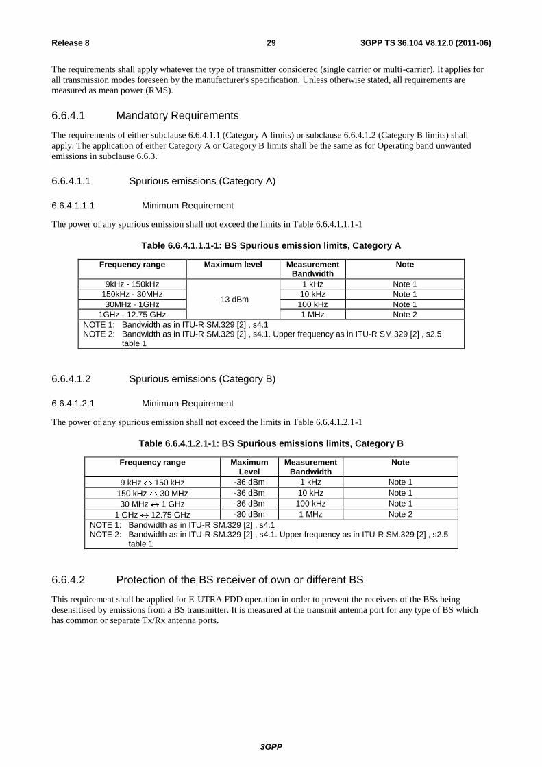
3GPP
3GPP TS 36.104 V8.12.0 (2011-06) 29 Release 8
The requirements shall apply whatever the type of transmitter considered (single carrier or multi-carrier). It applies for
all transmission modes foreseen by the manufacturer's specification. Unless otherwise stated, all requirements are
measured as mean power (RMS).
6.6.4.1 Mandatory Requirements
The requirements of either subclause 6.6.4.1.1 (Category A limits) or subclause 6.6.4.1.2 (Category B limits) shall
apply. The application of either Category A or Category B limits shall be the same as for Operating band unwanted
emissions in subclause 6.6.3.
6.6.4.1.1 Spurious emissions (Category A)
6.6.4.1.1.1 Minimum Requirement
The power of any spurious emission shall not exceed the limits in Table 6.6.4.1.1.1-1
Table 6.6.4.1.1.1-1: BS Spurious emission limits, Category A
Frequency range Maximum level Measurement Bandwidth
Note
9kHz - 150kHz
-13 dBm
1 kHz Note 1
150kHz - 30MHz 10 kHz Note 1
30MHz - 1GHz 100 kHz Note 1
1GHz - 12.75 GHz 1 MHz Note 2
NOTE 1: Bandwidth as in ITU-R SM.329 [2] , s4.1 NOTE 2: Bandwidth as in ITU-R SM.329 [2] , s4.1. Upper frequency as in ITU-R SM.329 [2] , s2.5
table 1
6.6.4.1.2 Spurious emissions (Category B)
6.6.4.1.2.1 Minimum Requirement
The power of any spurious emission shall not exceed the limits in Table 6.6.4.1.2.1-1
Table 6.6.4.1.2.1-1: BS Spurious emissions limits, Category B
Frequency range Maximum Level
Measurement Bandwidth
Note
9 kHz 150 kHz -36 dBm 1 kHz Note 1
150 kHz 30 MHz -36 dBm 10 kHz Note 1
30 MHz 1 GHz -36 dBm 100 kHz Note 1
1 GHz 12.75 GHz -30 dBm 1 MHz Note 2
NOTE 1: Bandwidth as in ITU-R SM.329 [2] , s4.1 NOTE 2: Bandwidth as in ITU-R SM.329 [2] , s4.1. Upper frequency as in ITU-R SM.329 [2] , s2.5
table 1
6.6.4.2 Protection of the BS receiver of own or different BS
This requirement shall be applied for E-UTRA FDD operation in order to prevent the receivers of the BSs being
desensitised by emissions from a BS transmitter. It is measured at the transmit antenna port for any type of BS which
has common or separate Tx/Rx antenna ports.
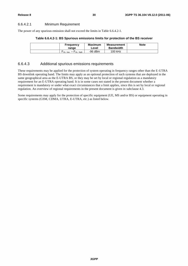
3GPP
3GPP TS 36.104 V8.12.0 (2011-06) 30 Release 8
6.6.4.2.1 Minimum Requirement
The power of any spurious emission shall not exceed the limits in Table 6.6.4.2-1.
Table 6.6.4.2-1: BS Spurious emissions limits for protection of the BS receiver
Frequency range
Maximum Level
Measurement Bandwidth
Note
FUL_low – FUL_high -96 dBm 100 kHz
6.6.4.3 Additional spurious emissions requirements
These requirements may be applied for the protection of system operating in frequency ranges other than the E-UTRA
BS downlink operating band. The limits may apply as an optional protection of such systems that are deployed in the
same geographical area as the E-UTRA BS, or they may be set by local or regional regulation as a mandatory
requirement for an E-UTRA operating band. It is in some cases not stated in the present document whether a
requirement is mandatory or under what exact circumstances that a limit applies, since this is set by local or regional
regulation. An overview of regional requirements in the present document is given in subclause 4.3.
Some requirements may apply for the protection of specific equipment (UE, MS and/or BS) or equipment operating in
specific systems (GSM, CDMA, UTRA, E-UTRA, etc.) as listed below.
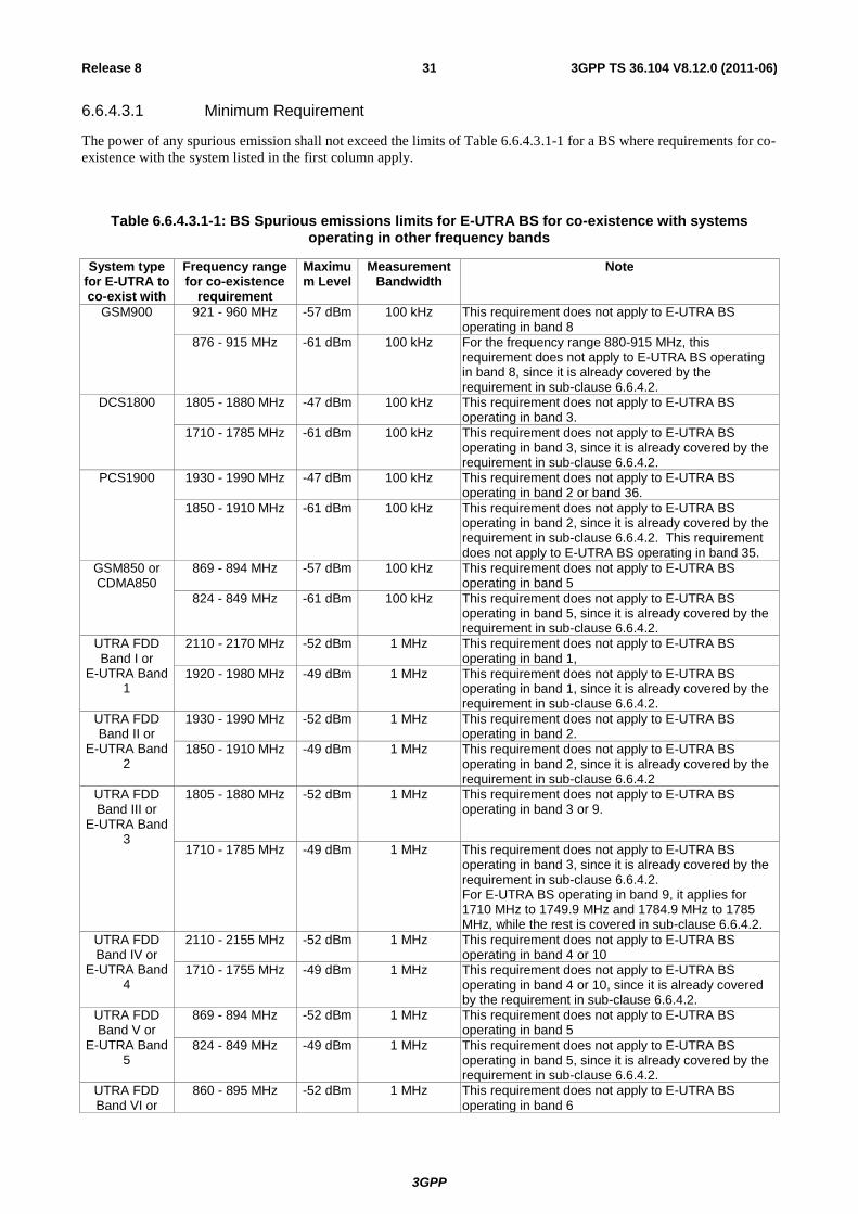
3GPP
3GPP TS 36.104 V8.12.0 (2011-06) 31 Release 8
6.6.4.3.1 Minimum Requirement
The power of any spurious emission shall not exceed the limits of Table 6.6.4.3.1-1 for a BS where requirements for co-
existence with the system listed in the first column apply.
Table 6.6.4.3.1-1: BS Spurious emissions limits for E-UTRA BS for co-existence with systems operating in other frequency bands
System type for E-UTRA to co-exist with
Frequency range for co-existence
requirement
Maximum Level
Measurement Bandwidth
Note
GSM900 921 - 960 MHz -57 dBm 100 kHz This requirement does not apply to E-UTRA BS operating in band 8
876 - 915 MHz -61 dBm 100 kHz For the frequency range 880-915 MHz, this requirement does not apply to E-UTRA BS operating in band 8, since it is already covered by the requirement in sub-clause 6.6.4.2.
DCS1800 1805 - 1880 MHz -47 dBm 100 kHz This requirement does not apply to E-UTRA BS operating in band 3.
1710 - 1785 MHz -61 dBm 100 kHz This requirement does not apply to E-UTRA BS operating in band 3, since it is already covered by the requirement in sub-clause 6.6.4.2.
PCS1900 1930 - 1990 MHz
-47 dBm 100 kHz This requirement does not apply to E-UTRA BS operating in band 2 or band 36.
1850 - 1910 MHz
-61 dBm 100 kHz This requirement does not apply to E-UTRA BS operating in band 2, since it is already covered by the requirement in sub-clause 6.6.4.2. This requirement does not apply to E-UTRA BS operating in band 35.
GSM850 or CDMA850
869 - 894 MHz -57 dBm 100 kHz This requirement does not apply to E-UTRA BS operating in band 5
824 - 849 MHz -61 dBm 100 kHz This requirement does not apply to E-UTRA BS operating in band 5, since it is already covered by the requirement in sub-clause 6.6.4.2.
UTRA FDD Band I or
E-UTRA Band 1
2110 - 2170 MHz -52 dBm 1 MHz This requirement does not apply to E-UTRA BS operating in band 1,
1920 - 1980 MHz
-49 dBm 1 MHz This requirement does not apply to E-UTRA BS operating in band 1, since it is already covered by the requirement in sub-clause 6.6.4.2.
UTRA FDD Band II or
E-UTRA Band 2
1930 - 1990 MHz
-52 dBm 1 MHz This requirement does not apply to E-UTRA BS operating in band 2.
1850 - 1910 MHz
-49 dBm 1 MHz This requirement does not apply to E-UTRA BS operating in band 2, since it is already covered by the requirement in sub-clause 6.6.4.2
UTRA FDD Band III or
E-UTRA Band 3
1805 - 1880 MHz
-52 dBm 1 MHz This requirement does not apply to E-UTRA BS operating in band 3 or 9.
1710 - 1785 MHz -49 dBm 1 MHz This requirement does not apply to E-UTRA BS operating in band 3, since it is already covered by the requirement in sub-clause 6.6.4.2. For E-UTRA BS operating in band 9, it applies for 1710 MHz to 1749.9 MHz and 1784.9 MHz to 1785 MHz, while the rest is covered in sub-clause 6.6.4.2.
UTRA FDD Band IV or
E-UTRA Band 4
2110 - 2155 MHz -52 dBm 1 MHz This requirement does not apply to E-UTRA BS operating in band 4 or 10
1710 - 1755 MHz -49 dBm 1 MHz This requirement does not apply to E-UTRA BS operating in band 4 or 10, since it is already covered by the requirement in sub-clause 6.6.4.2.
UTRA FDD Band V or
E-UTRA Band 5
869 - 894 MHz -52 dBm 1 MHz This requirement does not apply to E-UTRA BS operating in band 5
824 - 849 MHz -49 dBm 1 MHz This requirement does not apply to E-UTRA BS operating in band 5, since it is already covered by the requirement in sub-clause 6.6.4.2.
UTRA FDD Band VI or
860 - 895 MHz -52 dBm 1 MHz This requirement does not apply to E-UTRA BS operating in band 6
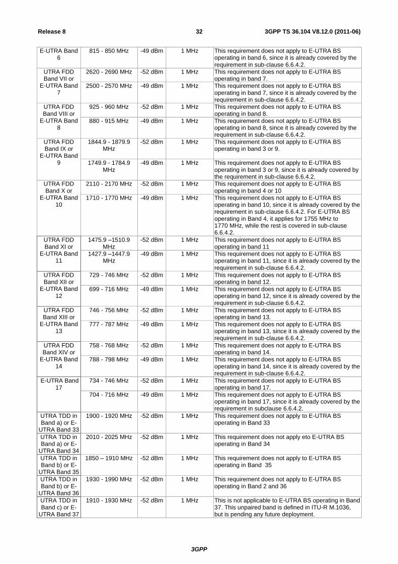
3GPP
3GPP TS 36.104 V8.12.0 (2011-06) 32 Release 8
E-UTRA Band 6
815 - 850 MHz -49 dBm 1 MHz This requirement does not apply to E-UTRA BS operating in band 6, since it is already covered by the requirement in sub-clause 6.6.4.2.
UTRA FDD Band VII or
E-UTRA Band 7
2620 - 2690 MHz -52 dBm 1 MHz This requirement does not apply to E-UTRA BS operating in band 7.
2500 - 2570 MHz -49 dBm 1 MHz This requirement does not apply to E-UTRA BS operating in band 7, since it is already covered by the requirement in sub-clause 6.6.4.2.
UTRA FDD Band VIII or
E-UTRA Band 8
925 - 960 MHz -52 dBm 1 MHz This requirement does not apply to E-UTRA BS operating in band 8.
880 - 915 MHz -49 dBm 1 MHz This requirement does not apply to E-UTRA BS operating in band 8, since it is already covered by the requirement in sub-clause 6.6.4.2.
UTRA FDD Band IX or
E-UTRA Band 9
1844.9 - 1879.9 MHz
-52 dBm 1 MHz This requirement does not apply to E-UTRA BS operating in band 3 or 9.
1749.9 - 1784.9 MHz
-49 dBm 1 MHz This requirement does not apply to E-UTRA BS operating in band 3 or 9, since it is already covered by the requirement in sub-clause 6.6.4.2.
UTRA FDD Band X or
E-UTRA Band 10
2110 - 2170 MHz -52 dBm 1 MHz This requirement does not apply to E-UTRA BS operating in band 4 or 10
1710 - 1770 MHz -49 dBm 1 MHz This requirement does not apply to E-UTRA BS operating in band 10, since it is already covered by the requirement in sub-clause 6.6.4.2. For E-UTRA BS operating in Band 4, it applies for 1755 MHz to 1770 MHz, while the rest is covered in sub-clause 6.6.4.2.
UTRA FDD Band XI or
E-UTRA Band 11
1475.9 –1510.9 MHz
-52 dBm 1 MHz This requirement does not apply to E-UTRA BS operating in band 11
1427.9 –1447.9 MHz
-49 dBm 1 MHz This requirement does not apply to E-UTRA BS operating in band 11, since it is already covered by the requirement in sub-clause 6.6.4.2.
UTRA FDD Band XII or
E-UTRA Band 12
729 - 746 MHz -52 dBm 1 MHz This requirement does not apply to E-UTRA BS operating in band 12.
699 - 716 MHz -49 dBm 1 MHz This requirement does not apply to E-UTRA BS operating in band 12, since it is already covered by the requirement in sub-clause 6.6.4.2.
UTRA FDD Band XIII or
E-UTRA Band 13
746 - 756 MHz -52 dBm 1 MHz This requirement does not apply to E-UTRA BS operating in band 13.
777 - 787 MHz -49 dBm 1 MHz This requirement does not apply to E-UTRA BS operating in band 13, since it is already covered by the requirement in sub-clause 6.6.4.2.
UTRA FDD Band XIV or
E-UTRA Band 14
758 - 768 MHz -52 dBm 1 MHz This requirement does not apply to E-UTRA BS operating in band 14.
788 - 798 MHz -49 dBm 1 MHz This requirement does not apply to E-UTRA BS operating in band 14, since it is already covered by the requirement in sub-clause 6.6.4.2.
E-UTRA Band 17
734 - 746 MHz -52 dBm 1 MHz This requirement does not apply to E-UTRA BS operating in band 17.
704 - 716 MHz -49 dBm 1 MHz This requirement does not apply to E-UTRA BS operating in band 17, since it is already covered by the requirement in subclause 6.6.4.2.
UTRA TDD in Band a) or E-
UTRA Band 33
1900 - 1920 MHz
-52 dBm 1 MHz This requirement does not apply to E-UTRA BS operating in Band 33
UTRA TDD in Band a) or E-
UTRA Band 34
2010 - 2025 MHz -52 dBm 1 MHz This requirement does not apply eto E-UTRA BS operating in Band 34
UTRA TDD in Band b) or E-
UTRA Band 35
1850 – 1910 MHz
-52 dBm 1 MHz This requirement does not apply to E-UTRA BS operating in Band 35
UTRA TDD in Band b) or E-
UTRA Band 36
1930 - 1990 MHz -52 dBm 1 MHz This requirement does not apply to E-UTRA BS operating in Band 2 and 36
UTRA TDD in Band c) or E-
UTRA Band 37
1910 - 1930 MHz -52 dBm 1 MHz This is not applicable to E-UTRA BS operating in Band 37. This unpaired band is defined in ITU-R M.1036, but is pending any future deployment.
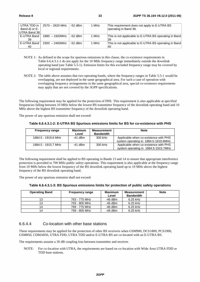
3GPP
3GPP TS 36.104 V8.12.0 (2011-06) 33 Release 8
UTRA TDD in Band d) or E-
UTRA Band 38
2570 – 2620 MHz -52 dBm 1 MHz This requirement does not apply to E-UTRA BS operating in Band 38.
E-UTRA Band 39
1880 – 1920MHz -52 dBm 1 MHz This is not applicable to E-UTRA BS operating in Band 39
E-UTRA Band 40
2300 – 2400MHz -52 dBm 1 MHz This is not applicable to E-UTRA BS operating in Band 40
NOTE 1: As defined in the scope for spurious emissions in this clause, the co-existence requirements in
Table 6.6.4.3.1-1 do not apply for the 10 MHz frequency range immediately outside the downlink
operating band (see Table 5.5-1). Emission limits for this excluded frequency range may be covered by
local or regional requirements.
NOTE 2: The table above assumes that two operating bands, where the frequency ranges in Table 5.5-1 would be
overlapping, are not deployed in the same geographical area. For such a case of operation with
overlapping frequency arrangements in the same geographical area, special co-existence requirements
may apply that are not covered by the 3GPP specifications.
The following requirement may be applied for the protection of PHS. This requirement is also applicable at specified
frequencies falling between 10 MHz below the lowest BS transmitter frequency of the downlink operating band and 10
MHz above the highest BS transmitter frequency of the downlink operating band.
The power of any spurious emission shall not exceed:
Table 6.6.4.3.1-2: E-UTRA BS Spurious emissions limits for BS for co-existence with PHS
Frequency range Maximum Level
Measurement Bandwidth
Note
1884.5 - 1919.6 MHz -41 dBm 300 kHz Applicable when co-existence with PHS system operating in. 1884.5-1919.6MHz.
1884.5 - 1915.7 MHz -41 dBm 300 kHz Applicable when co-existence with PHS system operating in 1884.5-1915.7MHz
The following requirement shall be applied to BS operating in Bands 13 and 14 to ensure that appropriate interference
protection is provided to 700 MHz public safety operations. This requirement is also applicable at the frequency range
from 10 MHz below the lowest frequency of the BS downlink operating band up to 10 MHz above the highest
frequency of the BS downlink operating band.
The power of any spurious emission shall not exceed:
Table 6.6.4.3.1-3: BS Spurious emissions limits for protection of public safety operations
Operating Band Frequency range Maximum Level
Measurement Bandwidth
Note
13 763 - 775 MHz -46 dBm 6.25 kHz
13 793 - 805 MHz -46 dBm 6.25 kHz
14 769 - 775 MHz -46 dBm 6.25 kHz
14 799 - 805 MHz -46 dBm 6.25 kHz
6.6.4.4 Co-location with other base stations
These requirements may be applied for the protection of other BS receivers when GSM900, DCS1800, PCS1900,
GSM850, CDMA850, UTRA FDD, UTRA TDD and/or E-UTRA BS are co-located with an E-UTRA BS.
The requirements assume a 30 dB coupling loss between transmitter and receiver.
NOTE: For co-location with UTRA, the requirements are based on co-location with Wide Area UTRA FDD or
TDD base stations.
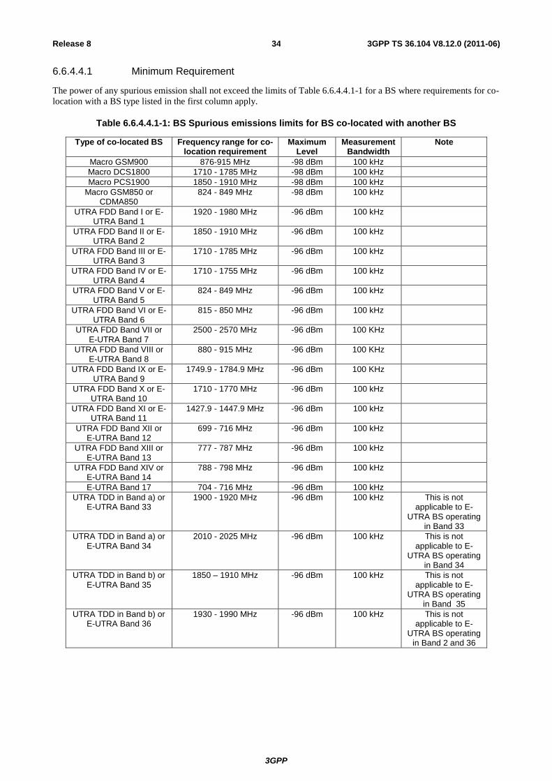
3GPP
3GPP TS 36.104 V8.12.0 (2011-06) 34 Release 8
6.6.4.4.1 Minimum Requirement
The power of any spurious emission shall not exceed the limits of Table 6.6.4.4.1-1 for a BS where requirements for co-
location with a BS type listed in the first column apply.
Table 6.6.4.4.1-1: BS Spurious emissions limits for BS co-located with another BS
Type of co-located BS Frequency range for co-location requirement
Maximum Level
Measurement Bandwidth
Note
Macro GSM900 876-915 MHz -98 dBm 100 kHz
Macro DCS1800 1710 - 1785 MHz -98 dBm 100 kHz
Macro PCS1900 1850 - 1910 MHz -98 dBm 100 kHz
Macro GSM850 or CDMA850
824 - 849 MHz -98 dBm 100 kHz
UTRA FDD Band I or E-UTRA Band 1
1920 - 1980 MHz
-96 dBm 100 kHz
UTRA FDD Band II or E-UTRA Band 2
1850 - 1910 MHz
-96 dBm 100 kHz
UTRA FDD Band III or E-UTRA Band 3
1710 - 1785 MHz -96 dBm 100 kHz
UTRA FDD Band IV or E-UTRA Band 4
1710 - 1755 MHz -96 dBm 100 kHz
UTRA FDD Band V or E-UTRA Band 5
824 - 849 MHz -96 dBm 100 kHz
UTRA FDD Band VI or E-UTRA Band 6
815 - 850 MHz -96 dBm 100 kHz
UTRA FDD Band VII or E-UTRA Band 7
2500 - 2570 MHz -96 dBm 100 KHz
UTRA FDD Band VIII or E-UTRA Band 8
880 - 915 MHz -96 dBm 100 KHz
UTRA FDD Band IX or E-UTRA Band 9
1749.9 - 1784.9 MHz -96 dBm 100 KHz
UTRA FDD Band X or E-UTRA Band 10
1710 - 1770 MHz -96 dBm 100 kHz
UTRA FDD Band XI or E-UTRA Band 11
1427.9 - 1447.9 MHz -96 dBm 100 kHz
UTRA FDD Band XII or E-UTRA Band 12
699 - 716 MHz -96 dBm 100 kHz
UTRA FDD Band XIII or E-UTRA Band 13
777 - 787 MHz -96 dBm 100 kHz
UTRA FDD Band XIV or E-UTRA Band 14
788 - 798 MHz -96 dBm 100 kHz
E-UTRA Band 17 704 - 716 MHz -96 dBm 100 kHz
UTRA TDD in Band a) or E-UTRA Band 33
1900 - 1920 MHz
-96 dBm 100 kHz This is not applicable to E-
UTRA BS operating in Band 33
UTRA TDD in Band a) or E-UTRA Band 34
2010 - 2025 MHz -96 dBm 100 kHz This is not applicable to E-
UTRA BS operating in Band 34
UTRA TDD in Band b) or E-UTRA Band 35
1850 – 1910 MHz
-96 dBm 100 kHz This is not applicable to E-
UTRA BS operating in Band 35
UTRA TDD in Band b) or E-UTRA Band 36
1930 - 1990 MHz -96 dBm 100 kHz This is not applicable to E-
UTRA BS operating in Band 2 and 36
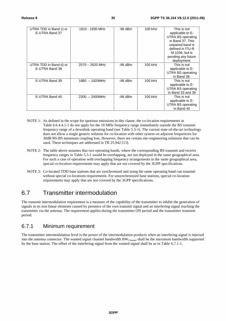
3GPP
3GPP TS 36.104 V8.12.0 (2011-06) 35 Release 8
UTRA TDD in Band c) or E-UTRA Band 37
1910 - 1930 MHz -96 dBm 100 kHz This is not applicable to E-
UTRA BS operating in Band 37. This unpaired band is defined in ITU-R M.1036, but is
pending any future deployment.
UTRA TDD in Band d) or E-UTRA Band 38
2570 – 2620 MHz -96 dBm 100 kHz This is not applicable to E-
UTRA BS operating in Band 38.
E-UTRA Band 39 1880 – 1920MHz -96 dBm 100 kHz This is not applicable to E-
UTRA BS operating in Band 33 and 39
E-UTRA Band 40 2300 – 2400MHz -96 dBm 100 kHz This is not applicable to E-
UTRA BS operating in Band 40
NOTE 1: As defined in the scope for spurious emissions in this clause, the co-location requirements in
Table 6.6.4.4.1-1 do not apply for the 10 MHz frequency range immediately outside the BS transmit
frequency range of a downlink operating band (see Table 5.5-1). The current state-of-the-art technology
does not allow a single generic solution for co-location with other system on adjacent frequencies for
30dB BS-BS minimum coupling loss. However, there are certain site-engineering solutions that can be
used. These techniques are addressed in TR 25.942 [13].
NOTE 2: The table above assumes that two operating bands, where the corresponding BS transmit and receive
frequency ranges in Table 5.5-1 would be overlapping, are not deployed in the same geographical area.
For such a case of operation with overlapping frequency arrangements in the same geographical area,
special co-location requirements may apply that are not covered by the 3GPP specifications.
NOTE 3: Co-located TDD base stations that are synchronized and using the same operating band can transmit
without special co-locations requirements. For unsynchronized base stations, special co-location
requirements may apply that are not covered by the 3GPP specifications.
6.7 Transmitter intermodulation
The transmit intermodulation requirement is a measure of the capability of the transmitter to inhibit the generation of
signals in its non linear elements caused by presence of the own transmit signal and an interfering signal reaching the
transmitter via the antenna. The requirement applies during the transmitter ON period and the transmitter transient
period.
6.7.1 Minimum requirement
The transmitter intermodulation level is the power of the intermodulation products when an interfering signal is injected
into the antenna connector. The wanted signal channel bandwidth BWChannel shall be the maximum bandwidth supported
by the base station. The offset of the interfering signal from the wanted signal shall be as in Table 6.7.1-1.
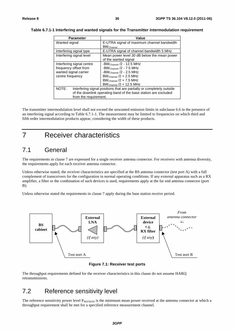
3GPP
3GPP TS 36.104 V8.12.0 (2011-06) 36 Release 8
Table 6.7.1-1 Interfering and wanted signals for the Transmitter intermodulation requirement
Parameter Value
Wanted signal E-UTRA signal of maximum channel bandwidth BWChannel
Interfering signal type E-UTRA signal of channel bandwidth 5 MHz
Interfering signal level Mean power level 30 dB below the mean power of the wanted signal
Interfering signal centre frequency offset from wanted signal carrier centre frequency
-BWChannel /2 - 12.5 MHz -BWChannel /2 - 7.5 MHz -BWChannel /2 - 2.5 MHz BWChannel /2 + 2.5 MHz BWChannel /2 + 7.5 MHz BWChannel /2 + 12.5 MHz
NOTE: Interfering signal positions that are partially or completely outside of the downlink operating band of the base station are excluded from the requirement.
The transmitter intermodulation level shall not exceed the unwanted emission limits in subclause 6.6 in the presence of
an interfering signal according to Table 6.7.1-1. The measurement may be limited to frequencies on which third and
fifth order intermodulation products appear, considering the width of these products.
7 Receiver characteristics
7.1 General
The requirements in clause 7 are expressed for a single receiver antenna connector. For receivers with antenna diversity,
the requirements apply for each receiver antenna connector.
Unless otherwise stated, the receiver characteristics are specified at the BS antenna connector (test port A) with a full
complement of transceivers for the configuration in normal operating conditions. If any external apparatus such as a RX
amplifier, a filter or the combination of such devices is used, requirements apply at the far end antenna connector (port
B).
Unless otherwise stated the requirements in clause 7 apply during the base station receive period.
BS
cabinet
Test port A Test port B
External
device
e.g.
RX filter
(if any)
External
LNA
(if any)
From
antenna connector
Figure 7.1: Receiver test ports
The throughput requirements defined for the receiver characteristics in this clause do not assume HARQ
retransmissions.
7.2 Reference sensitivity level
The reference sensitivity power level PREFSENS is the minimum mean power received at the antenna connector at which a
throughput requirement shall be met for a specified reference measurement channel.
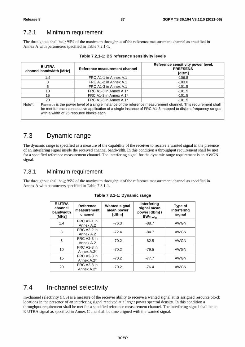
3GPP
3GPP TS 36.104 V8.12.0 (2011-06) 37 Release 8
7.2.1 Minimum requirement
The throughput shall be ≥ 95% of the maximum throughput of the reference measurement channel as specified in
Annex A with parameters specified in Table 7.2.1-1.
Table 7.2.1-1: BS reference sensitivity levels
E-UTRA channel bandwidth [MHz]
Reference measurement channel Reference sensitivity power level,
PREFSENS [dBm]
1.4 FRC A1-1 in Annex A.1 -106.8
3 FRC A1-2 in Annex A.1 -103.0
5 FRC A1-3 in Annex A.1 -101.5
10 FRC A1-3 in Annex A.1* -101.5
15 FRC A1-3 in Annex A.1* -101.5
20 FRC A1-3 in Annex A.1* -101.5
Note*: PREFSENS is the power level of a single instance of the reference measurement channel. This requirement shall be met for each consecutive application of a single instance of FRC A1-3 mapped to disjoint frequency ranges with a width of 25 resource blocks each
7.3 Dynamic range
The dynamic range is specified as a measure of the capability of the receiver to receive a wanted signal in the presence
of an interfering signal inside the received channel bandwidth. In this condition a throughput requirement shall be met
for a specified reference measurement channel. The interfering signal for the dynamic range requirement is an AWGN
signal.
7.3.1 Minimum requirement
The throughput shall be ≥ 95% of the maximum throughput of the reference measurement channel as specified in
Annex A with parameters specified in Table 7.3.1-1.
Table 7.3.1-1: Dynamic range
E-UTRA channel
bandwidth [MHz]
Reference measurement
channel
Wanted signal mean power
[dBm]
Interfering signal mean
power [dBm] / BWConfig
Type of interfering
signal
1.4 FRC A2-1 in Annex A.2
-76.3 -88.7 AWGN
3 FRC A2-2 in Annex A.2
-72.4 -84.7 AWGN
5 FRC A2-3 in Annex A.2
-70.2 -82.5 AWGN
10 FRC A2-3 in Annex A.2*
-70.2 -79.5 AWGN
15 FRC A2-3 in Annex A.2*
-70.2 -77.7 AWGN
20 FRC A2-3 in Annex A.2*
-70.2 -76.4 AWGN
7.4 In-channel selectivity
In-channel selectivity (ICS) is a measure of the receiver ability to receive a wanted signal at its assigned resource block
locations in the presence of an interfering signal received at a larger power spectral density. In this condition a
throughput requirement shall be met for a specified reference measurement channel. The interfering signal shall be an
E-UTRA signal as specified in Annex C and shall be time aligned with the wanted signal.
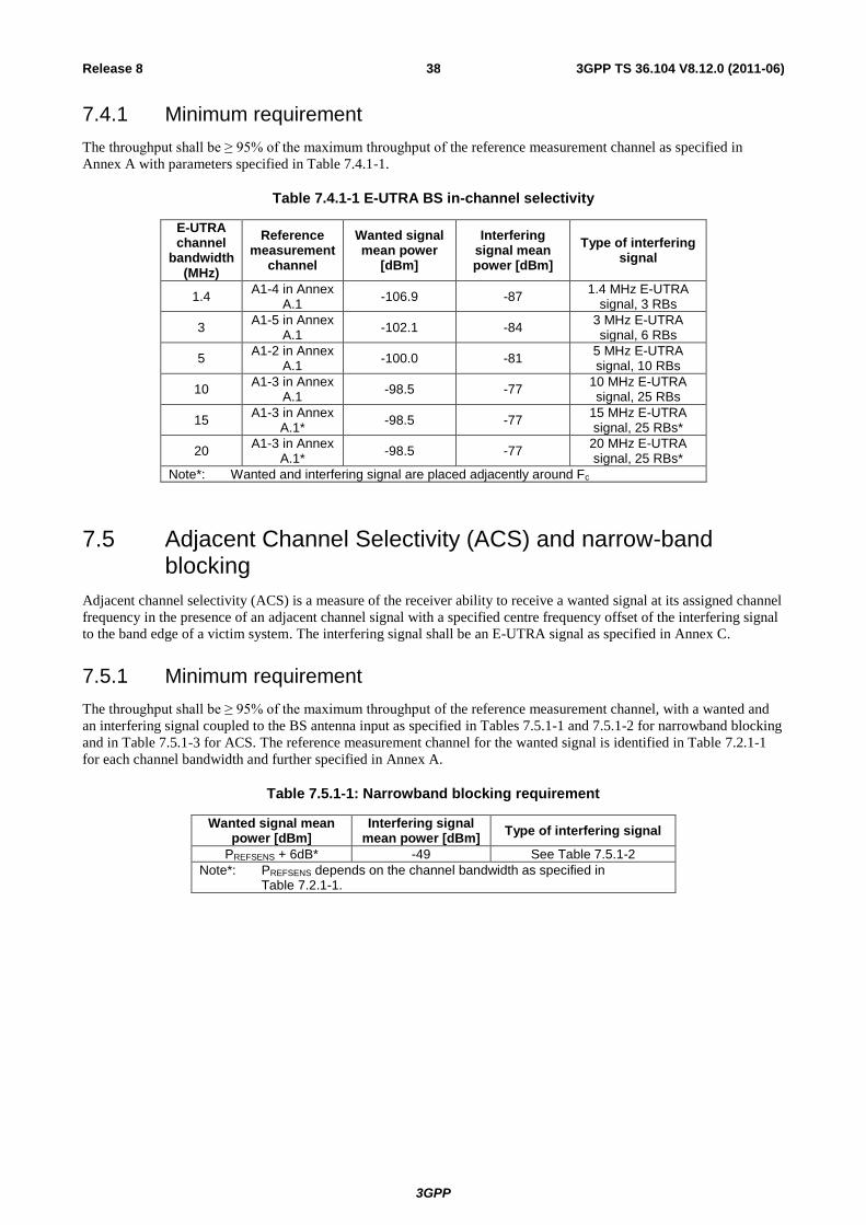
3GPP
3GPP TS 36.104 V8.12.0 (2011-06) 38 Release 8
7.4.1 Minimum requirement
The throughput shall be ≥ 95% of the maximum throughput of the reference measurement channel as specified in
Annex A with parameters specified in Table 7.4.1-1.
Table 7.4.1-1 E-UTRA BS in-channel selectivity
E-UTRA channel
bandwidth (MHz)
Reference measurement
channel
Wanted signal mean power
[dBm]
Interfering signal mean power [dBm]
Type of interfering signal
1.4 A1-4 in Annex
A.1 -106.9 -87
1.4 MHz E-UTRA signal, 3 RBs
3 A1-5 in Annex
A.1 -102.1 -84
3 MHz E-UTRA signal, 6 RBs
5 A1-2 in Annex
A.1 -100.0 -81
5 MHz E-UTRA signal, 10 RBs
10 A1-3 in Annex
A.1 -98.5 -77
10 MHz E-UTRA signal, 25 RBs
15 A1-3 in Annex
A.1* -98.5 -77
15 MHz E-UTRA signal, 25 RBs*
20 A1-3 in Annex
A.1* -98.5 -77
20 MHz E-UTRA signal, 25 RBs*
Note*: Wanted and interfering signal are placed adjacently around Fc
7.5 Adjacent Channel Selectivity (ACS) and narrow-band blocking
Adjacent channel selectivity (ACS) is a measure of the receiver ability to receive a wanted signal at its assigned channel
frequency in the presence of an adjacent channel signal with a specified centre frequency offset of the interfering signal
to the band edge of a victim system. The interfering signal shall be an E-UTRA signal as specified in Annex C.
7.5.1 Minimum requirement
The throughput shall be ≥ 95% of the maximum throughput of the reference measurement channel, with a wanted and
an interfering signal coupled to the BS antenna input as specified in Tables 7.5.1-1 and 7.5.1-2 for narrowband blocking
and in Table 7.5.1-3 for ACS. The reference measurement channel for the wanted signal is identified in Table 7.2.1-1
for each channel bandwidth and further specified in Annex A.
Table 7.5.1-1: Narrowband blocking requirement
Wanted signal mean power [dBm]
Interfering signal mean power [dBm]
Type of interfering signal
PREFSENS + 6dB* -49 See Table 7.5.1-2
Note*: PREFSENS depends on the channel bandwidth as specified in Table 7.2.1-1.
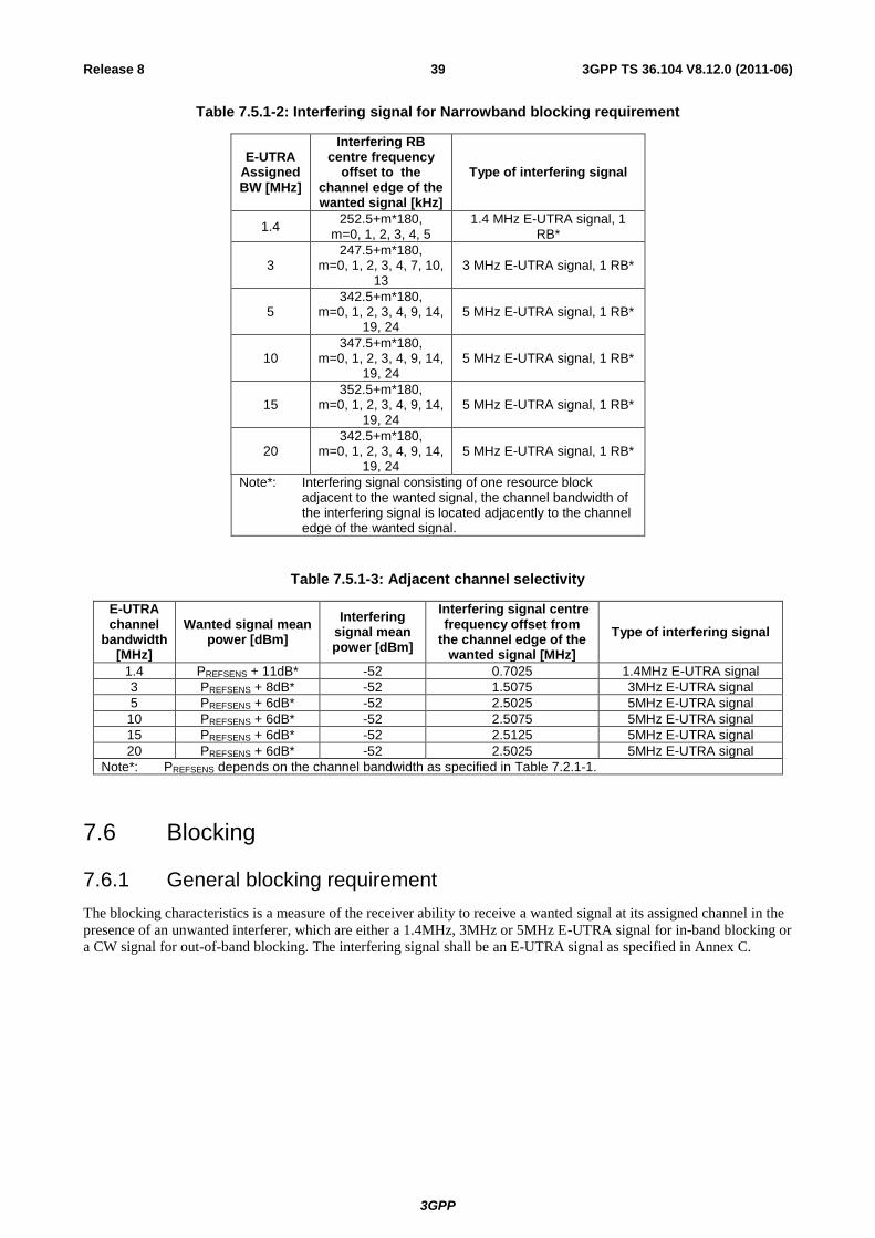
3GPP
3GPP TS 36.104 V8.12.0 (2011-06) 39 Release 8
Table 7.5.1-2: Interfering signal for Narrowband blocking requirement
E-UTRA Assigned BW [MHz]
Interfering RB centre frequency
offset to the channel edge of the wanted signal [kHz]
Type of interfering signal
1.4 252.5+m*180,
m=0, 1, 2, 3, 4, 5 1.4 MHz E-UTRA signal, 1
RB*
3 247.5+m*180,
m=0, 1, 2, 3, 4, 7, 10, 13
3 MHz E-UTRA signal, 1 RB*
5 342.5+m*180,
m=0, 1, 2, 3, 4, 9, 14, 19, 24
5 MHz E-UTRA signal, 1 RB*
10 347.5+m*180,
m=0, 1, 2, 3, 4, 9, 14, 19, 24
5 MHz E-UTRA signal, 1 RB*
15 352.5+m*180,
m=0, 1, 2, 3, 4, 9, 14, 19, 24
5 MHz E-UTRA signal, 1 RB*
20 342.5+m*180,
m=0, 1, 2, 3, 4, 9, 14, 19, 24
5 MHz E-UTRA signal, 1 RB*
Note*: Interfering signal consisting of one resource block adjacent to the wanted signal, the channel bandwidth of the interfering signal is located adjacently to the channel edge of the wanted signal.
Table 7.5.1-3: Adjacent channel selectivity
E-UTRA channel
bandwidth [MHz]
Wanted signal mean power [dBm]
Interfering signal mean power [dBm]
Interfering signal centre frequency offset from
the channel edge of the wanted signal [MHz]
Type of interfering signal
1.4 PREFSENS + 11dB* -52 0.7025 1.4MHz E-UTRA signal
3 PREFSENS + 8dB* -52 1.5075 3MHz E-UTRA signal
5 PREFSENS + 6dB* -52 2.5025 5MHz E-UTRA signal
10 PREFSENS + 6dB* -52 2.5075 5MHz E-UTRA signal
15 PREFSENS + 6dB* -52 2.5125 5MHz E-UTRA signal
20 PREFSENS + 6dB* -52 2.5025 5MHz E-UTRA signal
Note*: PREFSENS depends on the channel bandwidth as specified in Table 7.2.1-1.
7.6 Blocking
7.6.1 General blocking requirement
The blocking characteristics is a measure of the receiver ability to receive a wanted signal at its assigned channel in the
presence of an unwanted interferer, which are either a 1.4MHz, 3MHz or 5MHz E-UTRA signal for in-band blocking or
a CW signal for out-of-band blocking. The interfering signal shall be an E-UTRA signal as specified in Annex C.
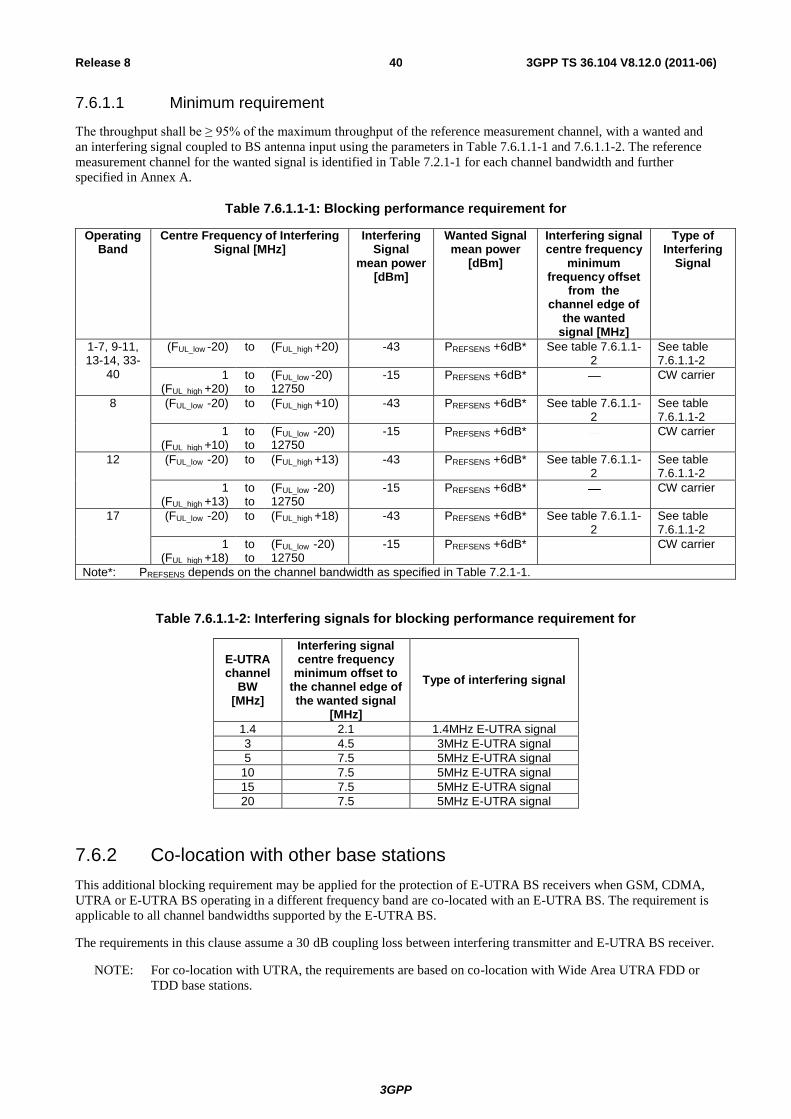
3GPP
3GPP TS 36.104 V8.12.0 (2011-06) 40 Release 8
7.6.1.1 Minimum requirement
The throughput shall be ≥ 95% of the maximum throughput of the reference measurement channel, with a wanted and
an interfering signal coupled to BS antenna input using the parameters in Table 7.6.1.1-1 and 7.6.1.1-2. The reference
measurement channel for the wanted signal is identified in Table 7.2.1-1 for each channel bandwidth and further
specified in Annex A.
Table 7.6.1.1-1: Blocking performance requirement for
Operating Band
Centre Frequency of Interfering Signal [MHz]
Interfering Signal
mean power [dBm]
Wanted Signal mean power
[dBm]
Interfering signal centre frequency
minimum frequency offset
from the channel edge of
the wanted signal [MHz]
Type of Interfering
Signal
1-7, 9-11, 13-14, 33-
40
(FUL_low -20) to (FUL_high +20) -43 PREFSENS +6dB* See table 7.6.1.1-2
See table 7.6.1.1-2
1 (FUL_high +20)
to to
(FUL_low -20) 12750
-15 PREFSENS +6dB* CW carrier
8 (FUL_low -20) to (FUL_high +10) -43 PREFSENS +6dB* See table 7.6.1.1-2
See table 7.6.1.1-2
1 (FUL_high +10)
to to
(FUL_low -20) 12750
-15 PREFSENS +6dB* CW carrier
12 (FUL_low -20) to (FUL_high +13) -43 PREFSENS +6dB* See table 7.6.1.1-2
See table 7.6.1.1-2
1 (FUL_high +13)
to to
(FUL_low -20) 12750
-15 PREFSENS +6dB* CW carrier
17 (FUL_low -20) to (FUL_high +18) -43 PREFSENS +6dB* See table 7.6.1.1-2
See table 7.6.1.1-2
1 (FUL_high +18)
to to
(FUL_low -20) 12750
-15 PREFSENS +6dB* CW carrier
Note*: PREFSENS depends on the channel bandwidth as specified in Table 7.2.1-1.
Table 7.6.1.1-2: Interfering signals for blocking performance requirement for
E-UTRA channel
BW [MHz]
Interfering signal centre frequency
minimum offset to the channel edge of the wanted signal
[MHz]
Type of interfering signal
1.4 2.1 1.4MHz E-UTRA signal
3 4.5 3MHz E-UTRA signal
5 7.5 5MHz E-UTRA signal
10 7.5 5MHz E-UTRA signal
15 7.5 5MHz E-UTRA signal
20 7.5 5MHz E-UTRA signal
7.6.2 Co-location with other base stations
This additional blocking requirement may be applied for the protection of E-UTRA BS receivers when GSM, CDMA,
UTRA or E-UTRA BS operating in a different frequency band are co-located with an E-UTRA BS. The requirement is
applicable to all channel bandwidths supported by the E-UTRA BS.
The requirements in this clause assume a 30 dB coupling loss between interfering transmitter and E-UTRA BS receiver.
NOTE: For co-location with UTRA, the requirements are based on co-location with Wide Area UTRA FDD or
TDD base stations.
3GPP
3GPP TS 36.104 V8.12.0 (2011-06) 41 Release 8
7.6.2.1 Minimum requirement
The throughput shall be ≥ 95% of the maximum throughput of the reference measurement channel, with a wanted and
an interfering signal coupled to BS antenna input using the parameters in Table 7.6.2.1-1. The reference measurement
channel for the wanted signal is identified in Table 7.2.1-1 for each channel bandwidth and further specified in Annex
A.
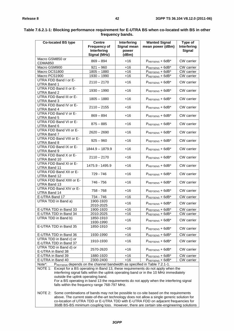
3GPP
3GPP TS 36.104 V8.12.0 (2011-06) 42 Release 8
Table 7.6.2.1-1: Blocking performance requirement for E-UTRA BS when co-located with BS in other frequency bands.
Co-located BS type Centre Frequency of
Interfering Signal (MHz)
Interfering Signal mean
power (dBm)
Wanted Signal mean power (dBm)
Type of Interfering
Signal
Macro GSM850 or CDMA850
869 – 894 +16 PREFSENS + 6dB* CW carrier
Macro GSM900 921 – 960 +16 PREFSENS + 6dB* CW carrier
Macro DCS1800 1805 – 1880 +16 PREFSENS + 6dB* CW carrier
Macro PCS1900 1930 – 1990 +16 PREFSENS + 6dB* CW carrier
UTRA FDD Band I or E-UTRA Band 1
2110 – 2170 +16 PREFSENS + 6dB* CW carrier
UTRA FDD Band II or E-UTRA Band 2
1930 – 1990 +16 PREFSENS + 6dB* CW carrier
UTRA FDD Band III or E-UTRA Band 3
1805 – 1880 +16 PREFSENS + 6dB* CW carrier
UTRA FDD Band IV or E-UTRA Band 4
2110 – 2155 +16 PREFSENS + 6dB* CW carrier
UTRA FDD Band V or E-UTRA Band 5
869 – 894 +16 PREFSENS + 6dB* CW carrier
UTRA FDD Band VI or E-UTRA Band 6
875 – 885 +16 PREFSENS + 6dB* CW carrier
UTRA FDD Band VII or E-UTRA Band 7
2620 – 2690 +16 PREFSENS + 6dB* CW carrier
UTRA FDD Band VIII or E-UTRA Band 8
925 – 960 +16 PREFSENS + 6dB* CW carrier
UTRA FDD Band IX or E-UTRA Band 9
1844.9 – 1879.9 +16 PREFSENS + 6dB* CW carrier
UTRA FDD Band X or E-UTRA Band 10
2110 – 2170 +16 PREFSENS + 6dB* CW carrier
UTRA FDD Band XI or E-UTRA Band 11
1475.9 - 1495.9 +16 PREFSENS + 6dB* CW carrier
UTRA FDD Band XII or E-UTRA Band 12
729 - 746 +16 PREFSENS + 6dB* CW carrier
UTRA FDD Band XIIII or E-UTRA Band 13
746 - 756 +16 PREFSENS + 6dB* CW carrier
UTRA FDD Band XIV or E-UTRA Band 14
758 - 768 +16 PREFSENS + 6dB* CW carrier
E-UTRA Band 17 734 - 746 +16 PREFSENS + 6dB* CW carrier
UTRA TDD in Band a) 1900-1920 2010-2025
+16 PREFSENS + 6dB* CW carrier
E-UTRA TDD in Band 33 1900-1920 +16 PREFSENS + 6dB* CW carrier
E-UTRA TDD in Band 34 2010-2025 +16 PREFSENS + 6dB* CW carrier
UTRA TDD in Band b) 1850-1910 1930-1990
+16 PREFSENS + 6dB* CW carrier
E-UTRA TDD in Band 35 1850-1910
+16 PREFSENS + 6dB* CW carrier
E-UTRA TDD in Band 36 1930-1990 +16 PREFSENS + 6dB* CW carrier
UTRA TDD in Band c) or E-UTRA TDD in Band 37
1910-1930 +16 PREFSENS + 6dB* CW carrier
UTRA TDD in Band d) or E-UTRA in Band 38
2570-2620 +16 PREFSENS + 6dB* CW carrier
E-UTRA in Band 39 1880-1920 +16 PREFSENS + 6dB* CW carrier
E-UTRA in Band 40 2300-2400 +16 PREFSENS + 6dB* CW carrier
Note*: PREFSENS depends on the channel bandwidth as specified in Table 7.2.1-1.
NOTE 1: Except for a BS operating in Band 13, these requirements do not apply when the interfering signal falls within the uplink operating band or in the 10 MHz immediately outside the uplink operating band. For a BS operating in band 13 the requirements do not apply when the interfering signal falls within the frequency range 768-797 MHz.
NOTE 2: Some combinations of bands may not be possible to co-site based on the requirements
above. The current state-of-the-art technology does not allow a single generic solution for co-location of UTRA TDD or E-UTRA TDD with E-UTRA FDD on adjacent frequencies for 30dB BS-BS minimum coupling loss. However, there are certain site-engineering solutions
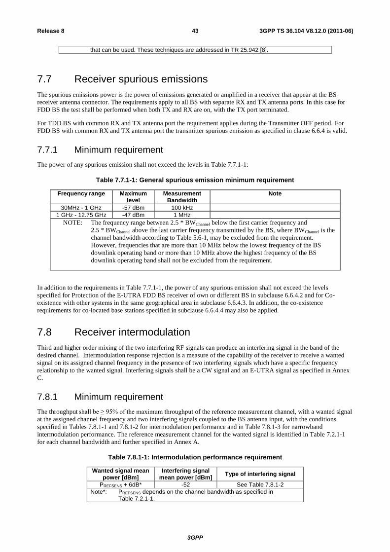
3GPP
3GPP TS 36.104 V8.12.0 (2011-06) 43 Release 8
that can be used. These techniques are addressed in TR 25.942 [8].
7.7 Receiver spurious emissions
The spurious emissions power is the power of emissions generated or amplified in a receiver that appear at the BS
receiver antenna connector. The requirements apply to all BS with separate RX and TX antenna ports. In this case for
FDD BS the test shall be performed when both TX and RX are on, with the TX port terminated.
For TDD BS with common RX and TX antenna port the requirement applies during the Transmitter OFF period. For
FDD BS with common RX and TX antenna port the transmitter spurious emission as specified in clause 6.6.4 is valid.
7.7.1 Minimum requirement
The power of any spurious emission shall not exceed the levels in Table 7.7.1-1:
Table 7.7.1-1: General spurious emission minimum requirement
Frequency range Maximum level
Measurement Bandwidth
Note
30MHz - 1 GHz -57 dBm 100 kHz
1 GHz - 12.75 GHz -47 dBm 1 MHz
NOTE: The frequency range between 2.5 * BWChannel below the first carrier frequency and
2.5 * BWChannel above the last carrier frequency transmitted by the BS, where BWChannel is the
channel bandwidth according to Table 5.6-1, may be excluded from the requirement.
However, frequencies that are more than 10 MHz below the lowest frequency of the BS
downlink operating band or more than 10 MHz above the highest frequency of the BS
downlink operating band shall not be excluded from the requirement.
In addition to the requirements in Table 7.7.1-1, the power of any spurious emission shall not exceed the levels
specified for Protection of the E-UTRA FDD BS receiver of own or different BS in subclause 6.6.4.2 and for Co-
existence with other systems in the same geographical area in subclause 6.6.4.3. In addition, the co-existence
requirements for co-located base stations specified in subclause 6.6.4.4 may also be applied.
7.8 Receiver intermodulation
Third and higher order mixing of the two interfering RF signals can produce an interfering signal in the band of the
desired channel. Intermodulation response rejection is a measure of the capability of the receiver to receive a wanted
signal on its assigned channel frequency in the presence of two interfering signals which have a specific frequency
relationship to the wanted signal. Interfering signals shall be a CW signal and an E-UTRA signal as specified in Annex
C.
7.8.1 Minimum requirement
The throughput shall be ≥ 95% of the maximum throughput of the reference measurement channel, with a wanted signal
at the assigned channel frequency and two interfering signals coupled to the BS antenna input, with the conditions
specified in Tables 7.8.1-1 and 7.8.1-2 for intermodulation performance and in Table 7.8.1-3 for narrowband
intermodulation performance. The reference measurement channel for the wanted signal is identified in Table 7.2.1-1
for each channel bandwidth and further specified in Annex A.
Table 7.8.1-1: Intermodulation performance requirement
Wanted signal mean power [dBm]
Interfering signal mean power [dBm]
Type of interfering signal
PREFSENS + 6dB* -52 See Table 7.8.1-2
Note*: PREFSENS depends on the channel bandwidth as specified in Table 7.2.1-1.
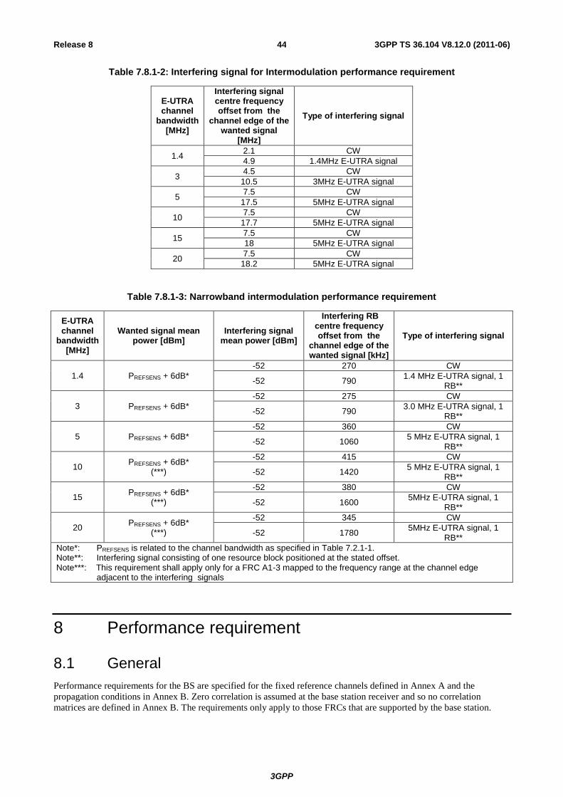
3GPP
3GPP TS 36.104 V8.12.0 (2011-06) 44 Release 8
Table 7.8.1-2: Interfering signal for Intermodulation performance requirement
E-UTRA channel
bandwidth [MHz]
Interfering signal centre frequency offset from the
channel edge of the wanted signal
[MHz]
Type of interfering signal
1.4 2.1 CW
4.9 1.4MHz E-UTRA signal
3 4.5 CW
10.5 3MHz E-UTRA signal
5 7.5 CW
17.5 5MHz E-UTRA signal
10 7.5 CW
17.7 5MHz E-UTRA signal
15 7.5 CW
18 5MHz E-UTRA signal
20 7.5 CW
18.2 5MHz E-UTRA signal
Table 7.8.1-3: Narrowband intermodulation performance requirement
E-UTRA channel
bandwidth [MHz]
Wanted signal mean power [dBm]
Interfering signal mean power [dBm]
Interfering RB centre frequency offset from the
channel edge of the wanted signal [kHz]
Type of interfering signal
1.4 PREFSENS + 6dB*
-52 270 CW
-52 790 1.4 MHz E-UTRA signal, 1
RB**
3 PREFSENS + 6dB*
-52 275 CW
-52 790 3.0 MHz E-UTRA signal, 1
RB**
5 PREFSENS + 6dB*
-52 360 CW
-52 1060 5 MHz E-UTRA signal, 1
RB**
10 PREFSENS + 6dB*
(***)
-52 415 CW
-52 1420 5 MHz E-UTRA signal, 1
RB**
15 PREFSENS + 6dB*
(***)
-52 380 CW
-52 1600 5MHz E-UTRA signal, 1
RB**
20 PREFSENS + 6dB*
(***)
-52 345 CW
-52 1780 5MHz E-UTRA signal, 1
RB**
Note*: PREFSENS is related to the channel bandwidth as specified in Table 7.2.1-1. Note**: Interfering signal consisting of one resource block positioned at the stated offset. Note***: This requirement shall apply only for a FRC A1-3 mapped to the frequency range at the channel edge
adjacent to the interfering signals
8 Performance requirement
8.1 General
Performance requirements for the BS are specified for the fixed reference channels defined in Annex A and the
propagation conditions in Annex B. Zero correlation is assumed at the base station receiver and so no correlation
matrices are defined in Annex B. The requirements only apply to those FRCs that are supported by the base station.
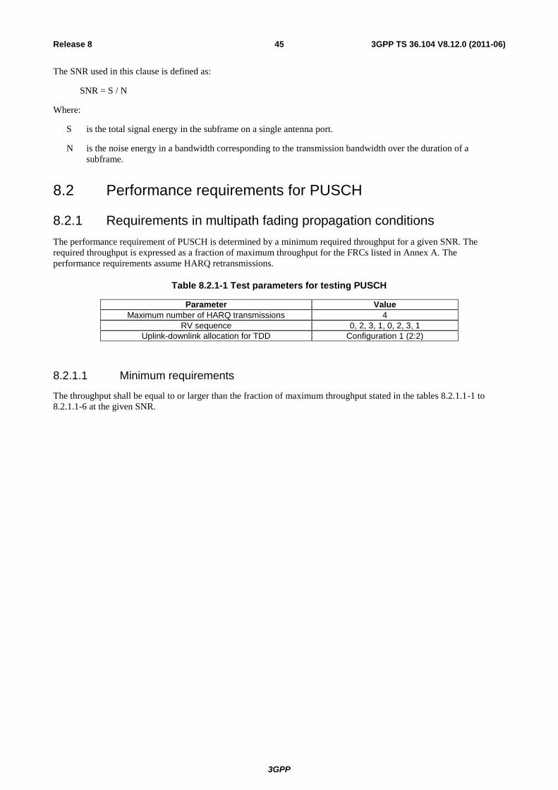
3GPP
3GPP TS 36.104 V8.12.0 (2011-06) 45 Release 8
The SNR used in this clause is defined as:
SNR = S / N
Where:
S is the total signal energy in the subframe on a single antenna port.
N is the noise energy in a bandwidth corresponding to the transmission bandwidth over the duration of a
subframe.
8.2 Performance requirements for PUSCH
8.2.1 Requirements in multipath fading propagation conditions
The performance requirement of PUSCH is determined by a minimum required throughput for a given SNR. The
required throughput is expressed as a fraction of maximum throughput for the FRCs listed in Annex A. The
performance requirements assume HARQ retransmissions.
Table 8.2.1-1 Test parameters for testing PUSCH
Parameter Value
Maximum number of HARQ transmissions 4
RV sequence 0, 2, 3, 1, 0, 2, 3, 1
Uplink-downlink allocation for TDD Configuration 1 (2:2)
8.2.1.1 Minimum requirements
The throughput shall be equal to or larger than the fraction of maximum throughput stated in the tables 8.2.1.1-1 to
8.2.1.1-6 at the given SNR.
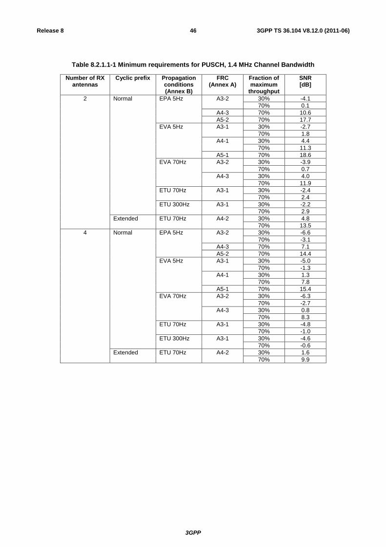
3GPP
3GPP TS 36.104 V8.12.0 (2011-06) 46 Release 8
Table 8.2.1.1-1 Minimum requirements for PUSCH, 1.4 MHz Channel Bandwidth
Number of RX antennas
Cyclic prefix Propagation conditions (Annex B)
FRC (Annex A)
Fraction of maximum
throughput
SNR [dB]
2 Normal EPA 5Hz A3-2 30% -4.1
70% 0.1
A4-3 70% 10.6
A5-2 70% 17.7
EVA 5Hz A3-1 30% -2.7
70% 1.8
A4-1 30% 4.4
70% 11.3
A5-1 70% 18.6
EVA 70Hz A3-2 30% -3.9
70% 0.7
A4-3 30% 4.0
70% 11.9
ETU 70Hz A3-1 30% -2.4
70% 2.4
ETU 300Hz A3-1 30% -2.2
70% 2.9
Extended ETU 70Hz A4-2 30% 4.8
70% 13.5
4 Normal EPA 5Hz A3-2 30% -6.6
70% -3.1
A4-3 70% 7.1
A5-2 70% 14.4
EVA 5Hz A3-1 30% -5.0
70% -1.3
A4-1 30% 1.3
70% 7.8
A5-1 70% 15.4
EVA 70Hz A3-2 30% -6.3
70% -2.7
A4-3 30% 0.8
70% 8.3
ETU 70Hz A3-1 30% -4.8
70% -1.0
ETU 300Hz A3-1 30% -4.6
70% -0.6
Extended ETU 70Hz A4-2 30% 1.6
70% 9.9

3GPP
3GPP TS 36.104 V8.12.0 (2011-06) 47 Release 8
Table 8.2.1.1-2 Minimum requirements for PUSCH, 3 MHz Channel Bandwidth
Number of RX antennas
Cyclic prefix Propagation conditions (Annex B)
FRC (Annex A)
Fraction of maximum
throughput
SNR [dB]
2 Normal EPA 5Hz A3-3 30% -4.1
70% 0.1
A4-4 70% 10.9
A5-3 70% 18.1
EVA 5Hz A3-1 30% -2.8
70% 1.8
A4-1 30% 4.3
70% 11.5
A5-1 70% 18.8
EVA 70Hz A3-3 30% -4.0
70% 0.6
A4-4 30% 4.7
70% 12.5
ETU 70Hz A3-1 30% -2.5
70% 2.4
ETU 300Hz A3-1 30% -2.2
70% 2.9
Extended ETU 70Hz A4-2 30% 4.7
70% 13.5
4 Normal EPA 5Hz A3-3 30% -6.8
70% -3.4
A4-4 70% 7.7
A5-3 70% 14.4
EVA 5Hz A3-1 30% -5.0
70% -1.3
A4-1 30% 1.2
70% 7.8
A5-1 70% 15.4
EVA 70Hz A3-3 30% -6.5
70% -2.9
A4-4 30% 1.6
70% 8.7
ETU 70Hz A3-1 30% -4.8
70% -0.9
ETU 300Hz A3-1 30% -4.6
70% -0.6
Extended ETU 70Hz A4-2 30% 1.5
70% 9.9
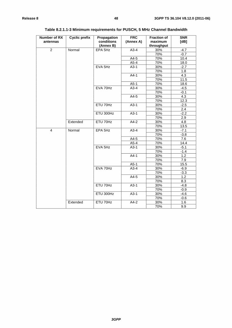
3GPP
3GPP TS 36.104 V8.12.0 (2011-06) 48 Release 8
Table 8.2.1.1-3 Minimum requirements for PUSCH, 5 MHz Channel Bandwidth
Number of RX antennas
Cyclic prefix Propagation conditions (Annex B)
FRC (Annex A)
Fraction of maximum
throughput
SNR [dB]
2 Normal EPA 5Hz A3-4 30% -4.7
70% -0.7
A4-5 70% 10.4
A5-4 70% 18.0
EVA 5Hz A3-1 30% -2.7
70% 1.8
A4-1 30% 4.3
70% 11.5
A5-1 70% 18.6
EVA 70Hz A3-4 30% -4.5
70% -0.1
A4-5 30% 4.3
70% 12.3
ETU 70Hz A3-1 30% -2.5
70% 2.4
ETU 300Hz A3-1 30% -2.2
70% 2.9
Extended ETU 70Hz A4-2 30% 4.8
70% 13.5
4 Normal EPA 5Hz A3-4 30% -7.1
70% -3.8
A4-5 70% 7.6
A5-4 70% 14.4
EVA 5Hz A3-1 30% -5.1
70% -1.4
A4-1 30% 1.2
70% 7.9
A5-1 70% 15.5
EVA 70Hz A3-4 30% -6.9
70% -3.3
A4-5 30% 1.2
70% 8.3
ETU 70Hz A3-1 30% -4.8
70% -0.9
ETU 300Hz A3-1 30% -4.6
70% -0.6
Extended ETU 70Hz A4-2 30% 1.6
70% 9.9
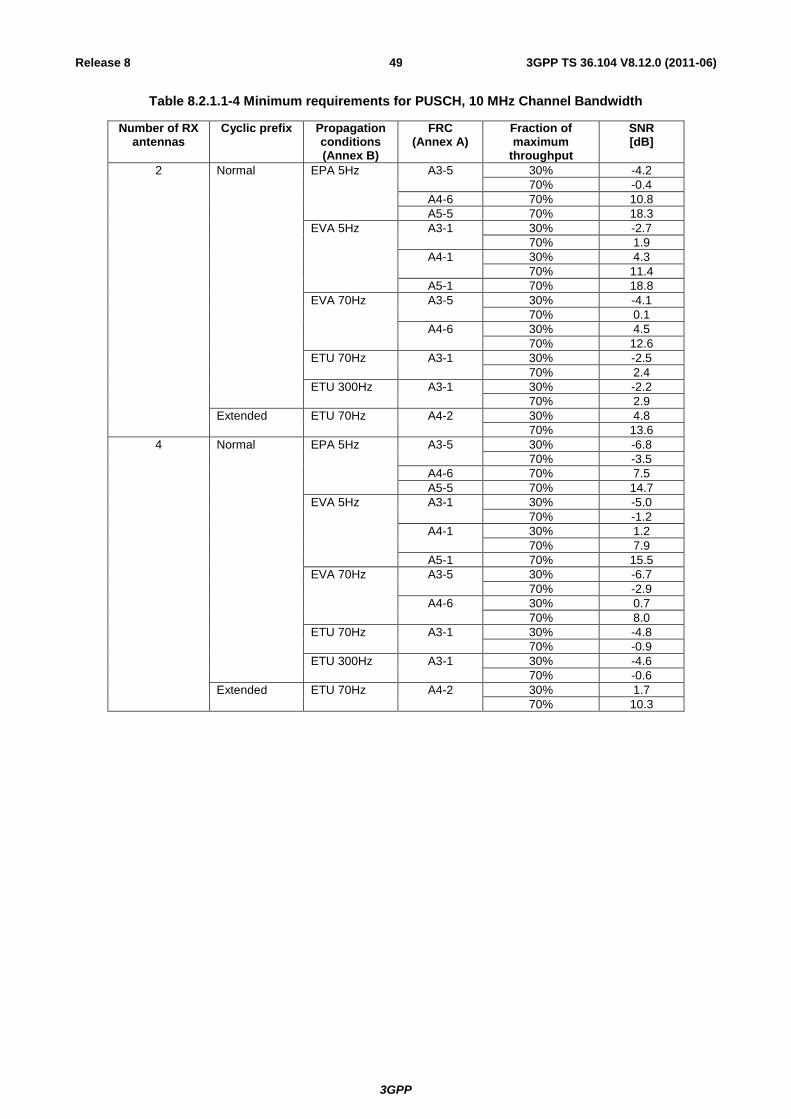
3GPP
3GPP TS 36.104 V8.12.0 (2011-06) 49 Release 8
Table 8.2.1.1-4 Minimum requirements for PUSCH, 10 MHz Channel Bandwidth
Number of RX antennas
Cyclic prefix Propagation conditions (Annex B)
FRC (Annex A)
Fraction of maximum
throughput
SNR [dB]
2 Normal EPA 5Hz A3-5 30% -4.2
70% -0.4
A4-6 70% 10.8
A5-5 70% 18.3
EVA 5Hz A3-1 30% -2.7
70% 1.9
A4-1 30% 4.3
70% 11.4
A5-1 70% 18.8
EVA 70Hz A3-5 30% -4.1
70% 0.1
A4-6 30% 4.5
70% 12.6
ETU 70Hz A3-1 30% -2.5
70% 2.4
ETU 300Hz A3-1 30% -2.2
70% 2.9
Extended ETU 70Hz A4-2 30% 4.8
70% 13.6
4 Normal EPA 5Hz A3-5 30% -6.8
70% -3.5
A4-6 70% 7.5
A5-5 70% 14.7
EVA 5Hz A3-1 30% -5.0
70% -1.2
A4-1 30% 1.2
70% 7.9
A5-1 70% 15.5
EVA 70Hz A3-5 30% -6.7
70% -2.9
A4-6 30% 0.7
70% 8.0
ETU 70Hz A3-1 30% -4.8
70% -0.9
ETU 300Hz A3-1 30% -4.6
70% -0.6
Extended ETU 70Hz A4-2 30% 1.7
70% 10.3

3GPP
3GPP TS 36.104 V8.12.0 (2011-06) 50 Release 8
Table 8.2.1.1-5 Minimum requirements for PUSCH, 15 MHz Channel Bandwidth
Number of RX antennas
Cyclic prefix Propagation conditions (Annex B)
FRC (Annex A)
Fraction of maximum
throughput
SNR [dB]
2 Normal EPA 5Hz A3-6 30% -4.5
70% -0.8
A4-7 70% 11.3
A5-6 70% 18.8
EVA 5Hz A3-1 30% -2.8
70% 1.8
A4-1 30% 4.2
70% 11.4
A5-1 70% 18.7
EVA 70Hz A3-6 30% -4.5
70% -0.3
A4-7 30% 4.2
70% 12.9
ETU 70Hz A3-1 30% -2.5
70% 2.4
ETU 300Hz A3-1 30% -2.2
70% 2.9
Extended ETU 70Hz A4-2 30% 4.9
70% 13.6
4 Normal EPA 5Hz A3-6 30% -7.2
70% -3.8
A4-7 70% 7.6
A5-6 70% 15.0
EVA 5Hz A3-1 30% -5.0
70% -1.2
A4-1 30% 1.2
70% 7.9
A5-1 70% 15.7
EVA 70Hz A3-6 30% -7.0
70% -3.3
A4-7 30% 0.7
70% 8.5
ETU 70Hz A3-1 30% -4.8
70% -1.0
ETU 300Hz A3-1 30% -4.6
70% -0.6
Extended ETU 70Hz A4-2 30% 1.6
70% 10.1
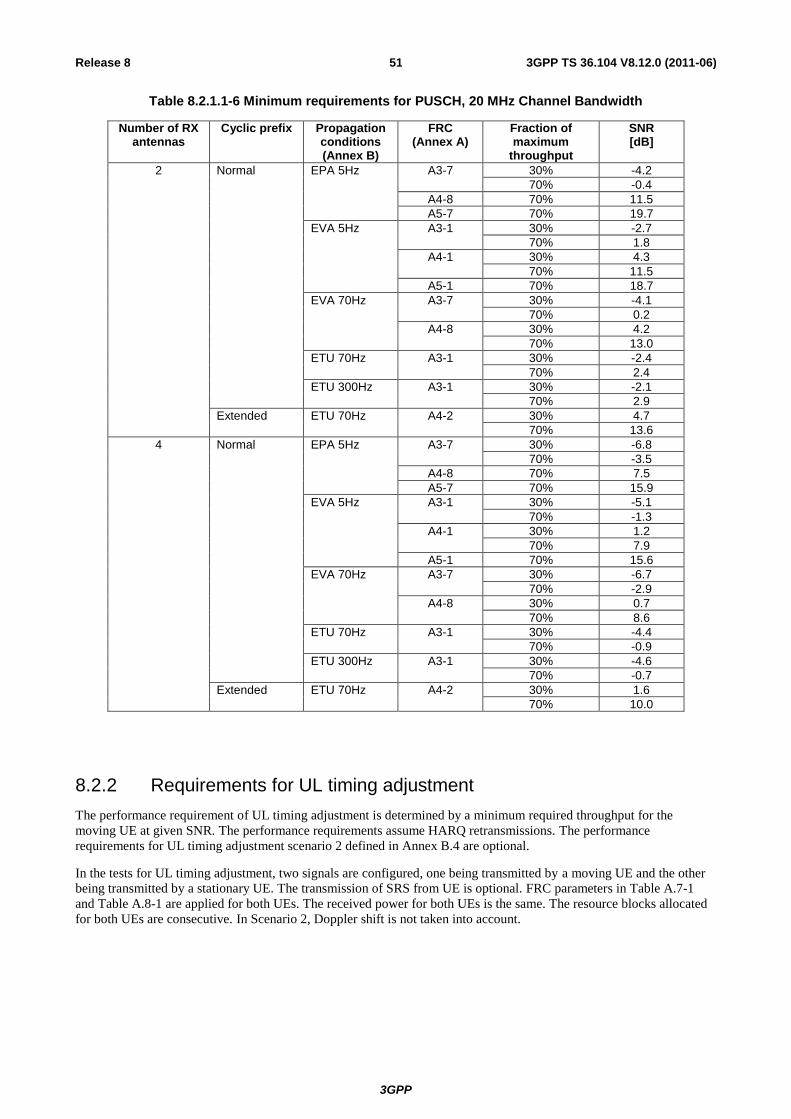
3GPP
3GPP TS 36.104 V8.12.0 (2011-06) 51 Release 8
Table 8.2.1.1-6 Minimum requirements for PUSCH, 20 MHz Channel Bandwidth
Number of RX antennas
Cyclic prefix Propagation conditions (Annex B)
FRC (Annex A)
Fraction of maximum
throughput
SNR [dB]
2 Normal EPA 5Hz A3-7 30% -4.2
70% -0.4
A4-8 70% 11.5
A5-7 70% 19.7
EVA 5Hz A3-1 30% -2.7
70% 1.8
A4-1 30% 4.3
70% 11.5
A5-1 70% 18.7
EVA 70Hz A3-7 30% -4.1
70% 0.2
A4-8 30% 4.2
70% 13.0
ETU 70Hz A3-1 30% -2.4
70% 2.4
ETU 300Hz A3-1 30% -2.1
70% 2.9
Extended ETU 70Hz A4-2 30% 4.7
70% 13.6
4 Normal EPA 5Hz A3-7 30% -6.8
70% -3.5
A4-8 70% 7.5
A5-7 70% 15.9
EVA 5Hz A3-1 30% -5.1
70% -1.3
A4-1 30% 1.2
70% 7.9
A5-1 70% 15.6
EVA 70Hz A3-7 30% -6.7
70% -2.9
A4-8 30% 0.7
70% 8.6
ETU 70Hz A3-1 30% -4.4
70% -0.9
ETU 300Hz A3-1 30% -4.6
70% -0.7
Extended ETU 70Hz A4-2 30% 1.6
70% 10.0
8.2.2 Requirements for UL timing adjustment
The performance requirement of UL timing adjustment is determined by a minimum required throughput for the
moving UE at given SNR. The performance requirements assume HARQ retransmissions. The performance
requirements for UL timing adjustment scenario 2 defined in Annex B.4 are optional.
In the tests for UL timing adjustment, two signals are configured, one being transmitted by a moving UE and the other
being transmitted by a stationary UE. The transmission of SRS from UE is optional. FRC parameters in Table A.7-1
and Table A.8-1 are applied for both UEs. The received power for both UEs is the same. The resource blocks allocated
for both UEs are consecutive. In Scenario 2, Doppler shift is not taken into account.
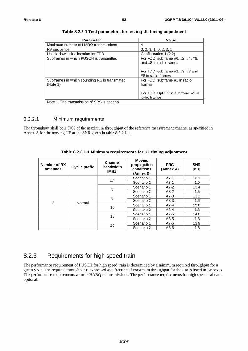
3GPP
3GPP TS 36.104 V8.12.0 (2011-06) 52 Release 8
Table 8.2.2-1 Test parameters for testing UL timing adjustment
Parameter Value
Maximum number of HARQ transmissions 4
RV sequence 0, 2, 3, 1, 0, 2, 3, 1
Uplink-downlink allocation for TDD Configuration 1 (2:2)
Subframes in which PUSCH is transmitted For FDD: subframe #0, #2, #4, #6, and #8 in radio frames For TDD: subframe #2, #3, #7 and #8 in radio frames
Subframes in which sounding RS is transmitted (Note 1)
For FDD: subframe #1 in radio frames For TDD: UpPTS in subframe #1 in radio frames
Note 1. The transmission of SRS is optional.
8.2.2.1 Minimum requirements
The throughput shall be ≥ 70% of the maximum throughput of the reference measurement channel as specified in
Annex A for the moving UE at the SNR given in table 8.2.2.1-1.
Table 8.2.2.1-1 Minimum requirements for UL timing adjustment
Number of RX antennas
Cyclic prefix Channel
Bandwidth [MHz]
Moving propagation conditions (Annex B)
FRC (Annex A)
SNR [dB]
2 Normal
1.4 Scenario 1 A7-1 13.1
Scenario 2 A8-1 -1.9
3 Scenario 1 A7-2 13.4
Scenario 2 A8-2 -1.5
5 Scenario 1 A7-3 13.2
Scenario 2 A8-3 -1.6
10 Scenario 1 A7-4 13.8
Scenario 2 A8-4 -1.8
15 Scenario 1 A7-5 14.0
Scenario 2 A8-5 -1.8
20 Scenario 1 A7-6 13.9
Scenario 2 A8-6 -1.8
8.2.3 Requirements for high speed train
The performance requirement of PUSCH for high speed train is determined by a minimum required throughput for a
given SNR. The required throughput is expressed as a fraction of maximum throughput for the FRCs listed in Annex A.
The performance requirements assume HARQ retransmissions. The performance requirements for high speed train are
optional.
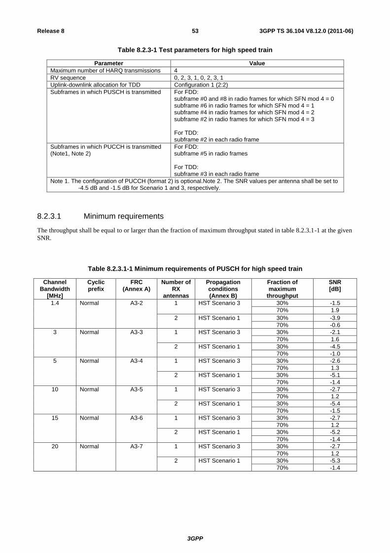
3GPP
3GPP TS 36.104 V8.12.0 (2011-06) 53 Release 8
Table 8.2.3-1 Test parameters for high speed train
Parameter Value
Maximum number of HARQ transmissions 4
RV sequence 0, 2, 3, 1, 0, 2, 3, 1
Uplink-downlink allocation for TDD Configuration 1 (2:2)
Subframes in which PUSCH is transmitted For FDD: subframe #0 and #8 in radio frames for which SFN mod 4 = 0 subframe #6 in radio frames for which SFN mod 4 = 1 subframe #4 in radio frames for which SFN mod 4 = 2 subframe #2 in radio frames for which SFN mod 4 = 3 For TDD: subframe #2 in each radio frame
Subframes in which PUCCH is transmitted (Note1, Note 2)
For FDD: subframe #5 in radio frames For TDD: subframe #3 in each radio frame
Note 1. The configuration of PUCCH (format 2) is optional.Note 2. The SNR values per antenna shall be set to -4.5 dB and -1.5 dB for Scenario 1 and 3, respectively.
8.2.3.1 Minimum requirements
The throughput shall be equal to or larger than the fraction of maximum throughput stated in table 8.2.3.1-1 at the given
SNR.
Table 8.2.3.1-1 Minimum requirements of PUSCH for high speed train
Channel Bandwidth
[MHz]
Cyclic prefix
FRC (Annex A)
Number of RX
antennas
Propagation conditions (Annex B)
Fraction of maximum
throughput
SNR [dB]
1.4 Normal A3-2 1 HST Scenario 3 30% -1.5
70% 1.9
2 HST Scenario 1 30% -3.9
70% -0.6
3 Normal A3-3 1 HST Scenario 3 30% -2.1
70% 1.6
2 HST Scenario 1 30% -4.5
70% -1.0
5 Normal A3-4 1 HST Scenario 3 30% -2.6
70% 1.3
2 HST Scenario 1 30% -5.1
70% -1.4
10 Normal A3-5 1 HST Scenario 3 30% -2.7
70% 1.2
2 HST Scenario 1 30% -5.4
70% -1.5
15 Normal A3-6 1 HST Scenario 3 30% -2.7
70% 1.2
2 HST Scenario 1 30% -5.2
70% -1.4
20 Normal A3-7 1 HST Scenario 3 30% -2.7
70% 1.2
2 HST Scenario 1 30% -5.3
70% -1.4
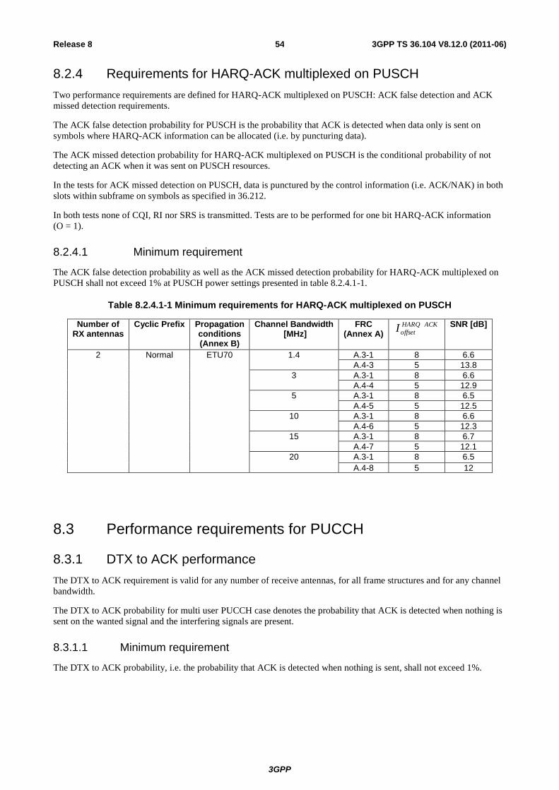
3GPP
3GPP TS 36.104 V8.12.0 (2011-06) 54 Release 8
8.2.4 Requirements for HARQ-ACK multiplexed on PUSCH
Two performance requirements are defined for HARQ-ACK multiplexed on PUSCH: ACK false detection and ACK
missed detection requirements.
The ACK false detection probability for PUSCH is the probability that ACK is detected when data only is sent on
symbols where HARQ-ACK information can be allocated (i.e. by puncturing data).
The ACK missed detection probability for HARQ-ACK multiplexed on PUSCH is the conditional probability of not
detecting an ACK when it was sent on PUSCH resources.
In the tests for ACK missed detection on PUSCH, data is punctured by the control information (i.e. ACK/NAK) in both
slots within subframe on symbols as specified in 36.212.
In both tests none of CQI, RI nor SRS is transmitted. Tests are to be performed for one bit HARQ-ACK information
(O = 1).
8.2.4.1 Minimum requirement
The ACK false detection probability as well as the ACK missed detection probability for HARQ-ACK multiplexed on
PUSCH shall not exceed 1% at PUSCH power settings presented in table 8.2.4.1-1.
Table 8.2.4.1-1 Minimum requirements for HARQ-ACK multiplexed on PUSCH
Number of RX antennas
Cyclic Prefix Propagation conditions (Annex B)
Channel Bandwidth [MHz]
FRC (Annex A)
ACKHARQ
offsetI
SNR [dB]
2
Normal ETU70 1.4 A.3-1 8 6.6
A.4-3 5 13.8
3 A.3-1 8 6.6
A.4-4 5 12.9
5 A.3-1 8 6.5
A.4-5 5 12.5
10 A.3-1 8 6.6
A.4-6 5 12.3
15 A.3-1 8 6.7
A.4-7 5 12.1
20 A.3-1 8 6.5
A.4-8 5 12
8.3 Performance requirements for PUCCH
8.3.1 DTX to ACK performance
The DTX to ACK requirement is valid for any number of receive antennas, for all frame structures and for any channel
bandwidth.
The DTX to ACK probability for multi user PUCCH case denotes the probability that ACK is detected when nothing is
sent on the wanted signal and the interfering signals are present.
8.3.1.1 Minimum requirement
The DTX to ACK probability, i.e. the probability that ACK is detected when nothing is sent, shall not exceed 1%.
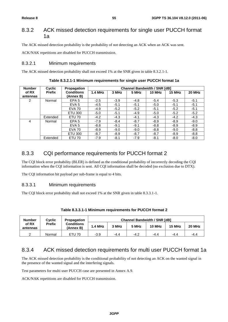
3GPP
3GPP TS 36.104 V8.12.0 (2011-06) 55 Release 8
8.3.2 ACK missed detection requirements for single user PUCCH format 1a
The ACK missed detection probability is the probability of not detecting an ACK when an ACK was sent.
ACK/NAK repetitions are disabled for PUCCH transmission.
8.3.2.1 Minimum requirements
The ACK missed detection probability shall not exceed 1% at the SNR given in table 8.3.2.1-1.
Table 8.3.2.1-1 Minimum requirements for single user PUCCH format 1a
Number of RX
antennas
Cyclic Prefix
Propagation Conditions (Annex B)
Channel Bandwidth / SNR [dB]
1.4 MHz 3 MHz 5 MHz 10 MHz 15 MHz 20 MHz
2 Normal EPA 5 -2.5 -3.9 -4.8 -5.4 -5.3 -5.1
EVA 5 -4.5 -5.1 -5.1 -5.0 -5.1 -5.1
EVA 70 -4.9 -5.2 -5.2 -5.1 -5.2 -5.1
ETU 300 -5.0 -5.1 -4.9 -5.0 -5.2 -5.2
Extended ETU 70 -4.2 -4.3 -4.1 -4.3 -4.2 -4.3
4 Normal EPA 5 -7.9 -8.4 -8.7 -8.9 -8.9 -9.0
EVA 5 -8.8 -9.1 -9.1 -8.8 -8.9 -8.9
EVA 70 -8.9 -9.0 -9.0 -8.8 -9.0 -8.8
ETU 300 -8.7 -8.9 -8.7 -8.7 -8.9 -8.8
Extended ETU 70 -7.9 -8.1 -7.9 -8.1 -8.0 -8.0
8.3.3 CQI performance requirements for PUCCH format 2
The CQI block error probability (BLER) is defined as the conditional probability of incorrectly decoding the CQI
information when the CQI information is sent. All CQI information shall be decoded (no exclusion due to DTX).
The CQI information bit payload per sub-frame is equal to 4 bits.
8.3.3.1 Minimum requirements
The CQI block error probability shall not exceed 1% at the SNR given in table 8.3.3.1-1.
Table 8.3.3.1-1 Minimum requirements for PUCCH format 2
Number of RX
antennas
Cyclic Prefix
Propagation Conditions (Annex B)
Channel Bandwidth / SNR [dB]
1.4 MHz 3 MHz 5 MHz 10 MHz 15 MHz 20 MHz
2 Normal ETU 70 -3.9 -4.4 -4.2 -4.4 -4.4 -4.4
8.3.4 ACK missed detection requirements for multi user PUCCH format 1a
The ACK missed detection probability is the conditional probability of not detecting an ACK on the wanted signal in
the presence of the wanted signal and the interfering signals.
Test parameters for multi user PUCCH case are presented in Annex A.9.
ACK/NAK repetitions are disabled for PUCCH transmission.
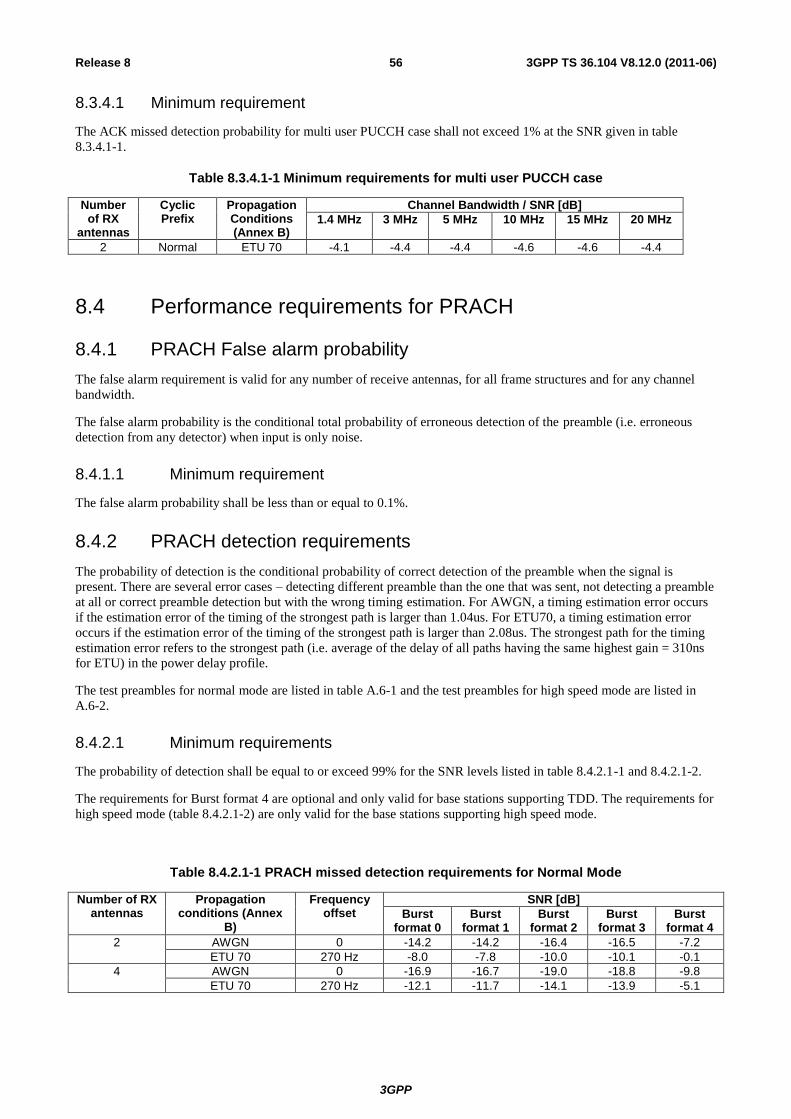
3GPP
3GPP TS 36.104 V8.12.0 (2011-06) 56 Release 8
8.3.4.1 Minimum requirement
The ACK missed detection probability for multi user PUCCH case shall not exceed 1% at the SNR given in table
8.3.4.1-1.
Table 8.3.4.1-1 Minimum requirements for multi user PUCCH case
Number of RX
antennas
Cyclic Prefix
Propagation Conditions (Annex B)
Channel Bandwidth / SNR [dB]
1.4 MHz 3 MHz 5 MHz 10 MHz 15 MHz 20 MHz
2 Normal ETU 70 -4.1 -4.4 -4.4 -4.6 -4.6 -4.4
8.4 Performance requirements for PRACH
8.4.1 PRACH False alarm probability
The false alarm requirement is valid for any number of receive antennas, for all frame structures and for any channel
bandwidth.
The false alarm probability is the conditional total probability of erroneous detection of the preamble (i.e. erroneous
detection from any detector) when input is only noise.
8.4.1.1 Minimum requirement
The false alarm probability shall be less than or equal to 0.1%.
8.4.2 PRACH detection requirements
The probability of detection is the conditional probability of correct detection of the preamble when the signal is
present. There are several error cases – detecting different preamble than the one that was sent, not detecting a preamble
at all or correct preamble detection but with the wrong timing estimation. For AWGN, a timing estimation error occurs
if the estimation error of the timing of the strongest path is larger than 1.04us. For ETU70, a timing estimation error
occurs if the estimation error of the timing of the strongest path is larger than 2.08us. The strongest path for the timing
estimation error refers to the strongest path (i.e. average of the delay of all paths having the same highest gain = 310ns
for ETU) in the power delay profile.
The test preambles for normal mode are listed in table A.6-1 and the test preambles for high speed mode are listed in
A.6-2.
8.4.2.1 Minimum requirements
The probability of detection shall be equal to or exceed 99% for the SNR levels listed in table 8.4.2.1-1 and 8.4.2.1-2.
The requirements for Burst format 4 are optional and only valid for base stations supporting TDD. The requirements for
high speed mode (table 8.4.2.1-2) are only valid for the base stations supporting high speed mode.
Table 8.4.2.1-1 PRACH missed detection requirements for Normal Mode
Number of RX antennas
Propagation conditions (Annex
B)
Frequency offset
SNR [dB]
Burst format 0
Burst format 1
Burst format 2
Burst format 3
Burst format 4
2 AWGN 0 -14.2 -14.2 -16.4 -16.5 -7.2
ETU 70 270 Hz -8.0 -7.8 -10.0 -10.1 -0.1
4 AWGN 0 -16.9 -16.7 -19.0 -18.8 -9.8
ETU 70 270 Hz -12.1 -11.7 -14.1 -13.9 -5.1
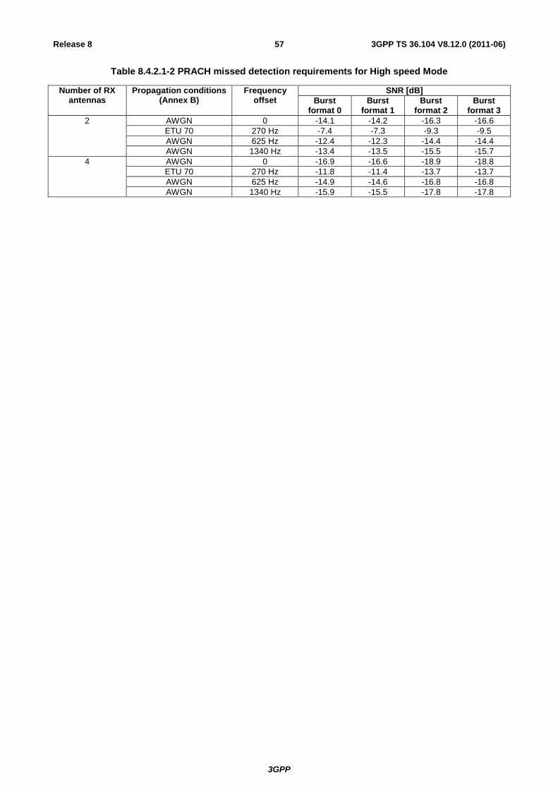
3GPP
3GPP TS 36.104 V8.12.0 (2011-06) 57 Release 8
Table 8.4.2.1-2 PRACH missed detection requirements for High speed Mode
Number of RX antennas
Propagation conditions (Annex B)
Frequency offset
SNR [dB]
Burst format 0
Burst format 1
Burst format 2
Burst format 3
2 AWGN 0 -14.1 -14.2 -16.3 -16.6
ETU 70 270 Hz -7.4 -7.3 -9.3 -9.5
AWGN 625 Hz -12.4 -12.3 -14.4 -14.4
AWGN 1340 Hz -13.4 -13.5 -15.5 -15.7
4 AWGN 0 -16.9 -16.6 -18.9 -18.8
ETU 70 270 Hz -11.8 -11.4 -13.7 -13.7
AWGN 625 Hz -14.9 -14.6 -16.8 -16.8
AWGN 1340 Hz -15.9 -15.5 -17.8 -17.8
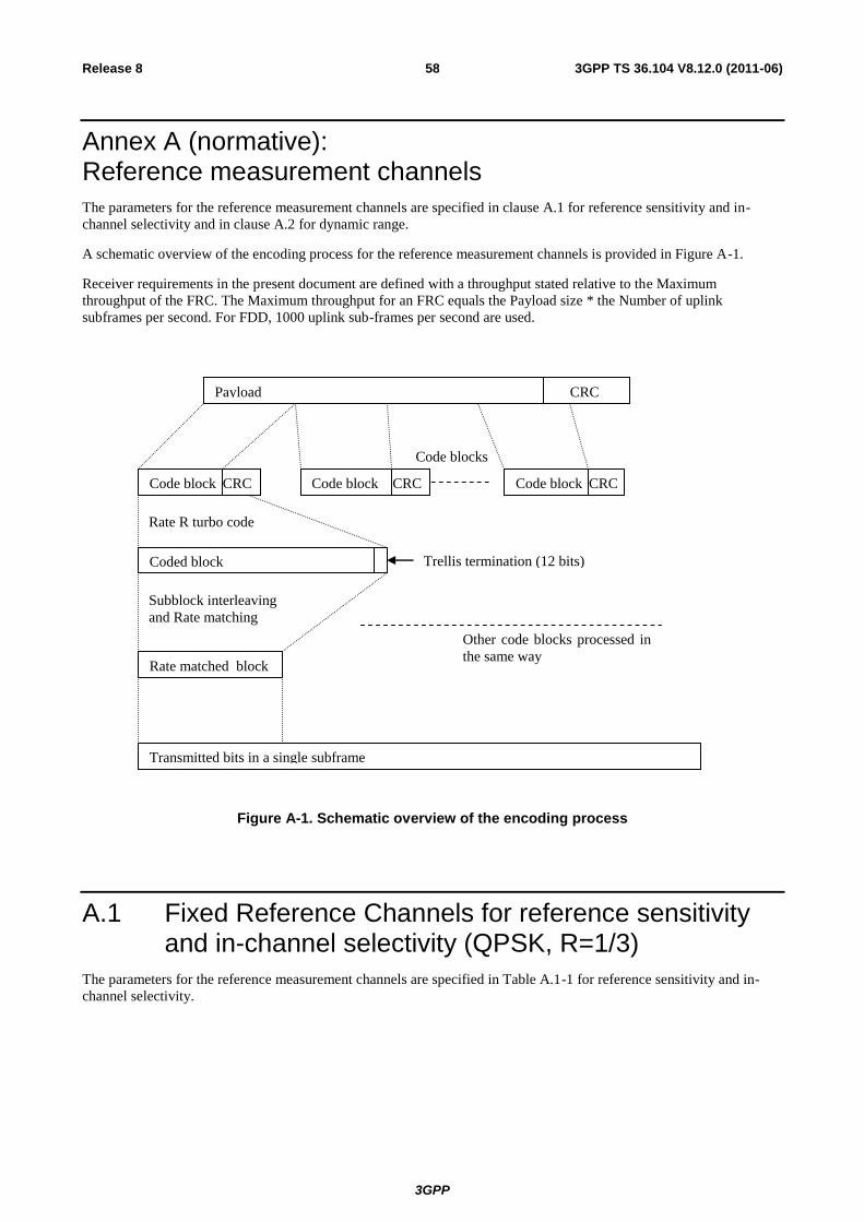
3GPP
3GPP TS 36.104 V8.12.0 (2011-06) 58 Release 8
Annex A (normative): Reference measurement channels
The parameters for the reference measurement channels are specified in clause A.1 for reference sensitivity and in-
channel selectivity and in clause A.2 for dynamic range.
A schematic overview of the encoding process for the reference measurement channels is provided in Figure A-1.
Receiver requirements in the present document are defined with a throughput stated relative to the Maximum
throughput of the FRC. The Maximum throughput for an FRC equals the Payload size * the Number of uplink
subframes per second. For FDD, 1000 uplink sub-frames per second are used.
Payload
Code block
Transmitted bits in a single subframe
Code block
Coded block Trellis termination (12 bits)
Rate matched block
Rate R turbo code
Code blocks
Subblock interleaving
and Rate matching
Code block
CRC
Other code blocks processed in
the same way
CRC CRC CRC
Figure A-1. Schematic overview of the encoding process
A.1 Fixed Reference Channels for reference sensitivity and in-channel selectivity (QPSK, R=1/3)
The parameters for the reference measurement channels are specified in Table A.1-1 for reference sensitivity and in-
channel selectivity.
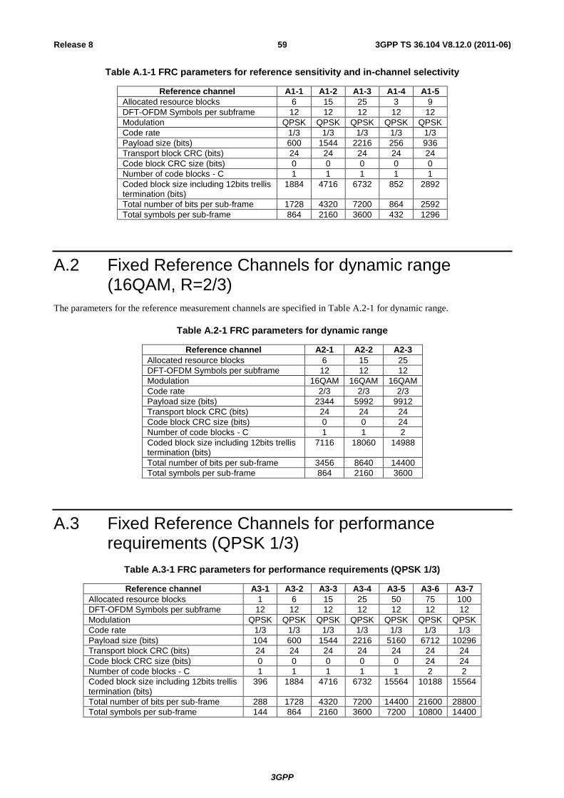
3GPP
3GPP TS 36.104 V8.12.0 (2011-06) 59 Release 8
Table A.1-1 FRC parameters for reference sensitivity and in-channel selectivity
Reference channel A1-1 A1-2 A1-3 A1-4 A1-5
Allocated resource blocks 6 15 25 3 9
DFT-OFDM Symbols per subframe 12 12 12 12 12
Modulation QPSK QPSK QPSK QPSK QPSK
Code rate 1/3 1/3 1/3 1/3 1/3
Payload size (bits) 600 1544 2216 256 936
Transport block CRC (bits) 24 24 24 24 24
Code block CRC size (bits) 0 0 0 0 0
Number of code blocks - C 1 1 1 1 1
Coded block size including 12bits trellis termination (bits)
1884 4716 6732 852 2892
Total number of bits per sub-frame 1728 4320 7200 864 2592
Total symbols per sub-frame 864 2160 3600 432 1296
A.2 Fixed Reference Channels for dynamic range (16QAM, R=2/3)
The parameters for the reference measurement channels are specified in Table A.2-1 for dynamic range.
Table A.2-1 FRC parameters for dynamic range
Reference channel A2-1 A2-2 A2-3
Allocated resource blocks 6 15 25
DFT-OFDM Symbols per subframe 12 12 12
Modulation 16QAM 16QAM 16QAM
Code rate 2/3 2/3 2/3
Payload size (bits) 2344 5992 9912
Transport block CRC (bits) 24 24 24
Code block CRC size (bits) 0 0 24
Number of code blocks - C 1 1 2
Coded block size including 12bits trellis termination (bits)
7116 18060 14988
Total number of bits per sub-frame 3456 8640 14400
Total symbols per sub-frame 864 2160 3600
A.3 Fixed Reference Channels for performance requirements (QPSK 1/3)
Table A.3-1 FRC parameters for performance requirements (QPSK 1/3)
Reference channel A3-1 A3-2 A3-3 A3-4 A3-5 A3-6 A3-7
Allocated resource blocks 1 6 15 25 50 75 100
DFT-OFDM Symbols per subframe 12 12 12 12 12 12 12
Modulation QPSK QPSK QPSK QPSK QPSK QPSK QPSK
Code rate 1/3 1/3 1/3 1/3 1/3 1/3 1/3
Payload size (bits) 104 600 1544 2216 5160 6712 10296
Transport block CRC (bits) 24 24 24 24 24 24 24
Code block CRC size (bits) 0 0 0 0 0 24 24
Number of code blocks - C 1 1 1 1 1 2 2
Coded block size including 12bits trellis termination (bits)
396 1884 4716 6732 15564 10188 15564
Total number of bits per sub-frame 288 1728 4320 7200 14400 21600 28800
Total symbols per sub-frame 144 864 2160 3600 7200 10800 14400
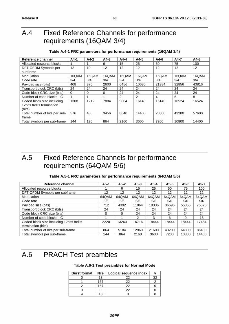
3GPP
3GPP TS 36.104 V8.12.0 (2011-06) 60 Release 8
A.4 Fixed Reference Channels for performance requirements (16QAM 3/4)
Table A.4-1 FRC parameters for performance requirements (16QAM 3/4)
Reference channel A4-1 A4-2 A4-3 A4-4 A4-5 A4-6 A4-7 A4-8
Allocated resource blocks 1 1 6 15 25 50 75 100
DFT-OFDM Symbols per subframe
12 10 12 12 12 12 12 12
Modulation 16QAM 16QAM 16QAM 16QAM 16QAM 16QAM 16QAM 16QAM
Code rate 3/4 3/4 3/4 3/4 3/4 3/4 3/4 3/4
Payload size (bits) 408 376 2600 6456 10680 21384 32856 43816
Transport block CRC (bits) 24 24 24 24 24 24 24 24
Code block CRC size (bits) 0 0 0 24 24 24 24 24
Number of code blocks - C 1 1 1 2 2 4 6 8
Coded block size including 12bits trellis termination (bits)
1308 1212 7884 9804 16140 16140 16524 16524
Total number of bits per sub-frame
576 480 3456 8640 14400 28800 43200 57600
Total symbols per sub-frame 144 120 864 2160 3600 7200 10800 14400
A.5 Fixed Reference Channels for performance requirements (64QAM 5/6)
Table A.5-1 FRC parameters for performance requirements (64QAM 5/6)
Reference channel A5-1 A5-2 A5-3 A5-4 A5-5 A5-6 A5-7
Allocated resource blocks 1 6 15 25 50 75 100
DFT-OFDM Symbols per subframe 12 12 12 12 12 12 12
Modulation 64QAM 64QAM 64QAM 64QAM 64QAM 64QAM 64QAM
Code rate 5/6 5/6 5/6 5/6 5/6 5/6 5/6
Payload size (bits) 712 4392 11064 18336 36696 55056 75376
Transport block CRC (bits) 24 24 24 24 24 24 24
Code block CRC size (bits) 0 0 24 24 24 24 24
Number of code blocks - C 1 1 2 3 6 9 13
Coded block size including 12bits trellis termination (bits)
2220 13260 16716 18444 18444 18444 17484
Total number of bits per sub-frame 864 5184 12960 21600 43200 64800 86400
Total symbols per sub-frame 144 864 2160 3600 7200 10800 14400
A.6 PRACH Test preambles
Table A.6-1 Test preambles for Normal Mode
Burst format Ncs Logical sequence index v
0 13 22 32
1 167 22 2
2 167 22 0
3 0 22 0
4 10 0 0
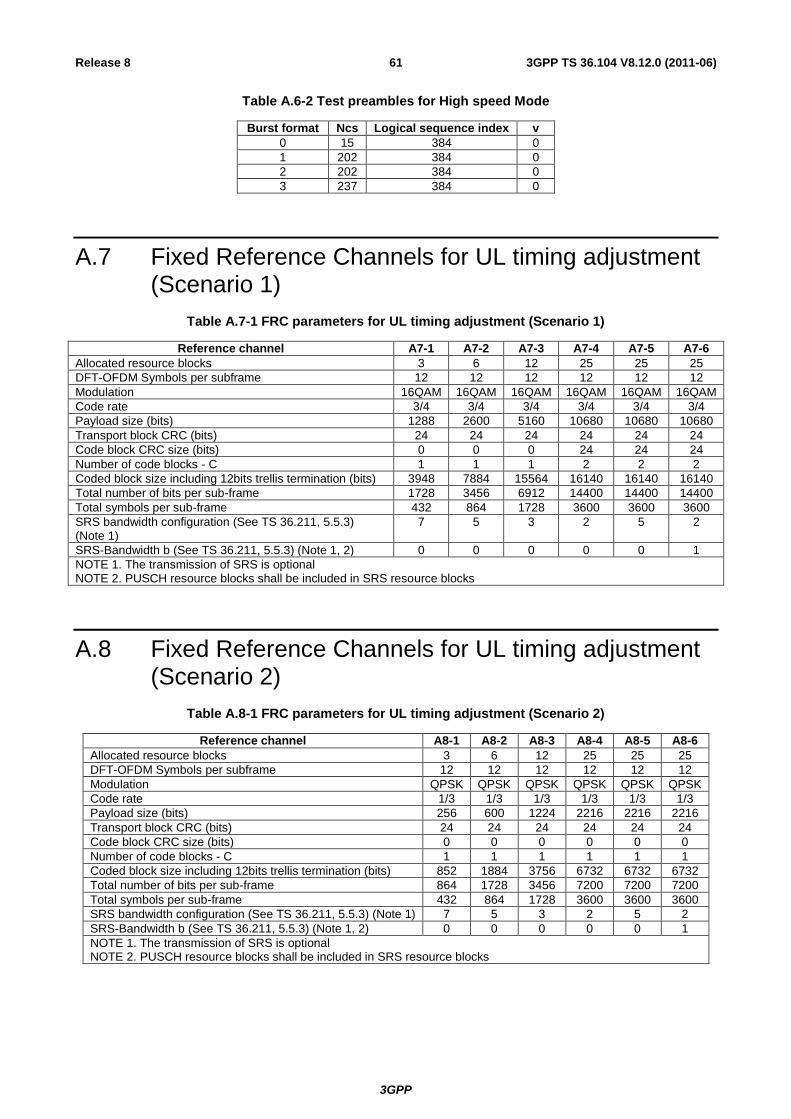
3GPP
3GPP TS 36.104 V8.12.0 (2011-06) 61 Release 8
Table A.6-2 Test preambles for High speed Mode
Burst format Ncs Logical sequence index v
0 15 384 0
1 202 384 0
2 202 384 0
3 237 384 0
A.7 Fixed Reference Channels for UL timing adjustment (Scenario 1)
Table A.7-1 FRC parameters for UL timing adjustment (Scenario 1)
Reference channel A7-1 A7-2 A7-3 A7-4 A7-5 A7-6
Allocated resource blocks 3 6 12 25 25 25
DFT-OFDM Symbols per subframe 12 12 12 12 12 12
Modulation 16QAM 16QAM 16QAM 16QAM 16QAM 16QAM
Code rate 3/4 3/4 3/4 3/4 3/4 3/4
Payload size (bits) 1288 2600 5160 10680 10680 10680
Transport block CRC (bits) 24 24 24 24 24 24
Code block CRC size (bits) 0 0 0 24 24 24
Number of code blocks - C 1 1 1 2 2 2
Coded block size including 12bits trellis termination (bits) 3948 7884 15564 16140 16140 16140
Total number of bits per sub-frame 1728 3456 6912 14400 14400 14400
Total symbols per sub-frame 432 864 1728 3600 3600 3600
SRS bandwidth configuration (See TS 36.211, 5.5.3) (Note 1)
7 5 3 2 5 2
SRS-Bandwidth b (See TS 36.211, 5.5.3) (Note 1, 2) 0 0 0 0 0 1
NOTE 1. The transmission of SRS is optional NOTE 2. PUSCH resource blocks shall be included in SRS resource blocks
A.8 Fixed Reference Channels for UL timing adjustment (Scenario 2)
Table A.8-1 FRC parameters for UL timing adjustment (Scenario 2)
Reference channel A8-1 A8-2 A8-3 A8-4 A8-5 A8-6
Allocated resource blocks 3 6 12 25 25 25
DFT-OFDM Symbols per subframe 12 12 12 12 12 12
Modulation QPSK QPSK QPSK QPSK QPSK QPSK
Code rate 1/3 1/3 1/3 1/3 1/3 1/3
Payload size (bits) 256 600 1224 2216 2216 2216
Transport block CRC (bits) 24 24 24 24 24 24
Code block CRC size (bits) 0 0 0 0 0 0
Number of code blocks - C 1 1 1 1 1 1
Coded block size including 12bits trellis termination (bits) 852 1884 3756 6732 6732 6732
Total number of bits per sub-frame 864 1728 3456 7200 7200 7200
Total symbols per sub-frame 432 864 1728 3600 3600 3600
SRS bandwidth configuration (See TS 36.211, 5.5.3) (Note 1) 7 5 3 2 5 2
SRS-Bandwidth b (See TS 36.211, 5.5.3) (Note 1, 2) 0 0 0 0 0 1
NOTE 1. The transmission of SRS is optional NOTE 2. PUSCH resource blocks shall be included in SRS resource blocks
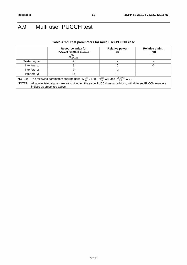
3GPP
3GPP TS 36.104 V8.12.0 (2011-06) 62 Release 8
A.9 Multi user PUCCH test
Table A.9-1 Test parameters for multi user PUCCH case
Resource index for PUCCH formats 1/1a/1b
(1)
PUCCHn
Relative power [dB]
Relative timing [ns]
Tested signal 2 - -
Interferer 1 1 0 0
Interferer 2 7 -3
Interferer 3 14 3
NOTE1: The following parameters shall be used 150cell
IDN , 0(1)
csN and 2PUCCH
shift.
NOTE2: All above listed signals are transmitted on the same PUCCH resource block, with different PUCCH resource indices as presented above.
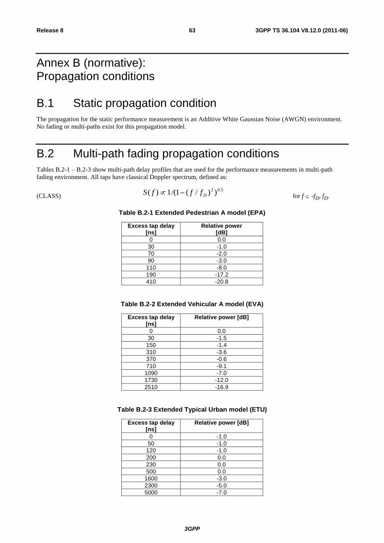
3GPP
3GPP TS 36.104 V8.12.0 (2011-06) 63 Release 8
Annex B (normative): Propagation conditions
B.1 Static propagation condition
The propagation for the static performance measurement is an Additive White Gaussian Noise (AWGN) environment.
No fading or multi-paths exist for this propagation model.
B.2 Multi-path fading propagation conditions
Tables B.2-1 – B.2-3 show multi-path delay profiles that are used for the performance measurements in multi-path
fading environment. All taps have classical Doppler spectrum, defined as:
(CLASS) 5.02 ))/(1/(1)( DfffS
for f -fD, fD.
Table B.2-1 Extended Pedestrian A model (EPA)
Excess tap delay [ns]
Relative power [dB]
0 0.0
30 -1.0
70 -2.0
90 -3.0
110 -8.0
190 -17.2
410 -20.8
Table B.2-2 Extended Vehicular A model (EVA)
Excess tap delay [ns]
Relative power [dB]
0 0.0
30 -1.5
150 -1.4
310 -3.6
370 -0.6
710 -9.1
1090 -7.0
1730 -12.0
2510 -16.9
Table B.2-3 Extended Typical Urban model (ETU)
Excess tap delay [ns]
Relative power [dB]
0 -1.0
50 -1.0
120 -1.0
200 0.0
230 0.0
500 0.0
1600 -3.0
2300 -5.0
5000 -7.0
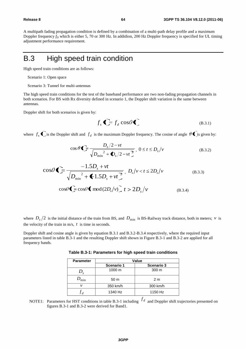
3GPP
3GPP TS 36.104 V8.12.0 (2011-06) 64 Release 8
A multipath fading propagation condition is defined by a combination of a multi-path delay profile and a maximum
Doppler frequency fD which is either 5, 70 or 300 Hz. In addidion, 200 Hz Doppler frequency is specified for UL timing
adjustment performance requirement.
B.3 High speed train condition
High speed train conditions are as follows:
Scenario 1: Open space
Scenario 3: Tunnel for multi-antennas
The high speed train conditions for the test of the baseband performance are two non-fading propagation channels in
both scenarios. For BS with Rx diversity defined in scenario 1, the Doppler shift variation is the same between
antennas.
Doppler shift for both scenarios is given by:
tftf ds cos (B.3.1)
where tfs is the Doppler shift and df is the maximum Doppler frequency. The cosine of angle t is given by:
22
min 2
2cos
vtDD
vtDt
s
s, vDt s0 (B.3.2)
22
min 5.1
5.1cos
vtDD
vtDt
s
s, vDtvD ss 2 (B.3.3)
)2( mod coscos vDtt s , vDt s2 (B.3.4)
where 2sD is the initial distance of the train from BS, and minD is BS-Railway track distance, both in meters; v is
the velocity of the train in m/s, t is time in seconds.
Doppler shift and cosine angle is given by equation B.3.1 and B.3.2-B.3.4 respectively, where the required input
parameters listed in table B.3-1 and the resulting Doppler shift shown in Figure B.3-1 and B.3-2 are applied for all
frequency bands.
Table B.3-1: Parameters for high speed train conditions
Parameter Value
Scenario 1 Scenario 3
sD 1000 m 300 m
minD 50 m 2 m
v 350 km/h 300 km/h
df 1340 Hz 1150 Hz
NOTE1: Parameters for HST conditions in table B.3-1 including df and Doppler shift trajectories presented on
figures B.3-1 and B.3-2 were derived for Band1.
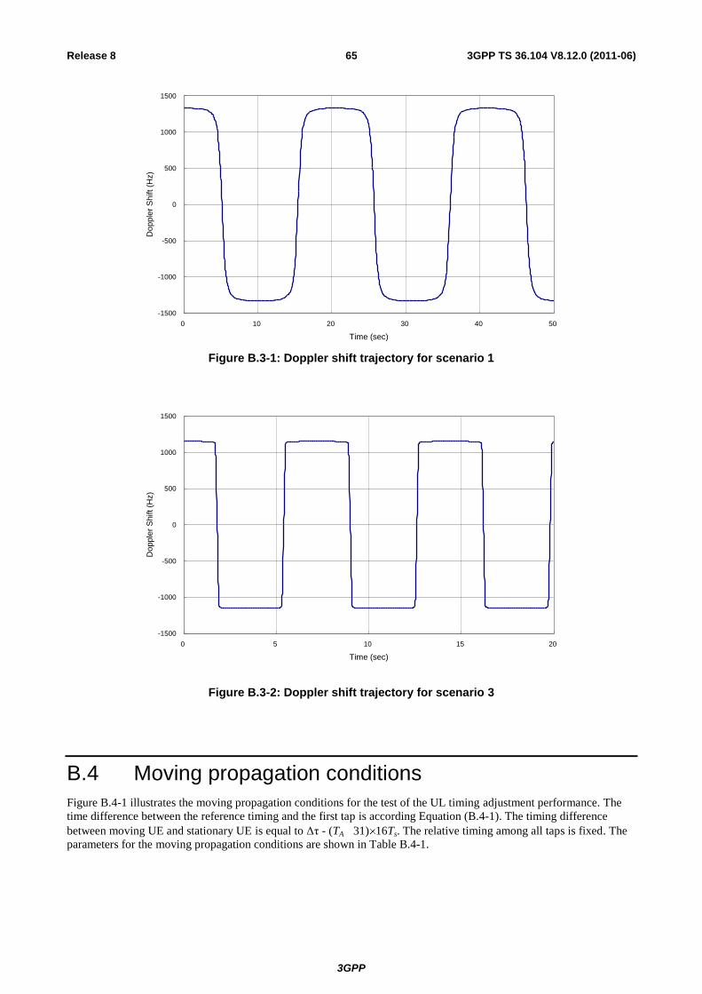
3GPP
3GPP TS 36.104 V8.12.0 (2011-06) 65 Release 8
-1500
-1000
-500
0
500
1000
1500
0 10 20 30 40 50
Time (sec)
Do
pple
r S
hift (H
z)
Figure B.3-1: Doppler shift trajectory for scenario 1
-1500
-1000
-500
0
500
1000
1500
0 5 10 15 20
Time (sec)
Do
pple
r S
hift (H
z)
Figure B.3-2: Doppler shift trajectory for scenario 3
B.4 Moving propagation conditions
Figure B.4-1 illustrates the moving propagation conditions for the test of the UL timing adjustment performance. The
time difference between the reference timing and the first tap is according Equation (B.4-1). The timing difference
between moving UE and stationary UE is equal to Δτ - (TA 31) 16Ts. The relative timing among all taps is fixed. The
parameters for the moving propagation conditions are shown in Table B.4-1.
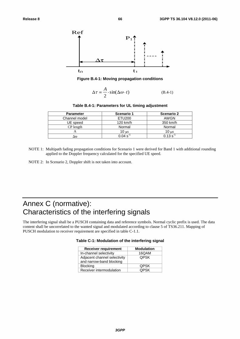
3GPP
3GPP TS 36.104 V8.12.0 (2011-06) 66 Release 8
t1
P1 Ref
t0
Figure B.4-1: Moving propagation conditions
)sin(2
tA
(B.4-1)
Table B.4-1: Parameters for UL timing adjustment
Parameter Scenario 1 Scenario 2
Channel model ETU200 AWGN
UE speed 120 km/h 350 km/h
CP length Normal Normal
A 10 s 10 s
0.04 s-1
0.13 s-1
NOTE 1: Multipath fading propagation conditions for Scenario 1 were derived for Band 1 with additional rounding
applied to the Doppler frequency calculated for the specified UE speed.
NOTE 2: In Scenario 2, Doppler shift is not taken into account.
Annex C (normative): Characteristics of the interfering signals
The interfering signal shall be a PUSCH containing data and reference symbols. Normal cyclic prefix is used. The data
content shall be uncorrelated to the wanted signal and modulated according to clause 5 of TS36.211. Mapping of
PUSCH modulation to receiver requirement are specified in table C-1.1.
Table C-1: Modulation of the interfering signal
Receiver requirement Modulation
In-channel selectivity 16QAM
Adjacent channel selectivity and narrow-band blocking
QPSK
Blocking QPSK
Receiver intermodulation QPSK
3GPP
3GPP TS 36.104 V8.12.0 (2011-06) 67 Release 8
Annex D (normative): Environmental requirements for the BS equipment
The BS equipment shall fulfil all the requirements in the full range of environmental conditions for the relevant
environmental class from the relevant IEC specifications listed below
60 721-3-3 "Stationary use at weather protected locations" [12];
60 721-3-4 "Stationary use at non weather protected locations" [13].
Normally it should be sufficient for all tests to be conducted using normal test conditions except where otherwise stated.
For guidance on the use of test conditions to be used in order to show compliance refer to TS 36.141.
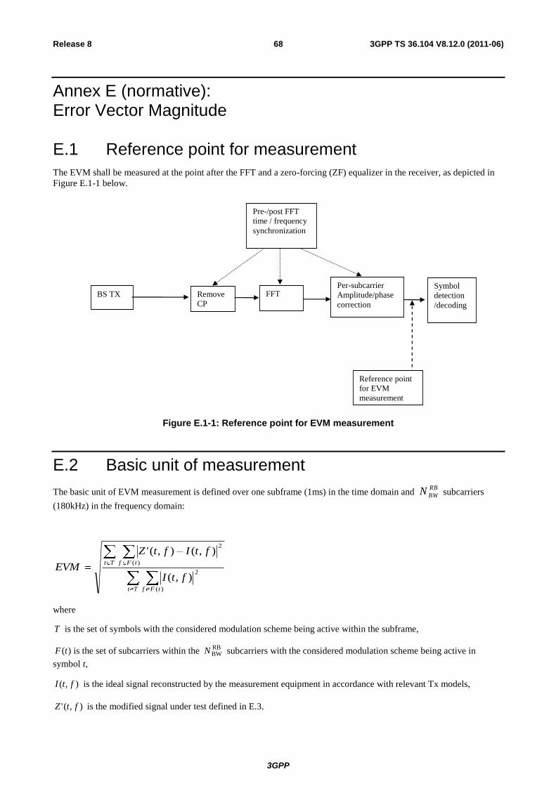
3GPP
3GPP TS 36.104 V8.12.0 (2011-06) 68 Release 8
Annex E (normative): Error Vector Magnitude
E.1 Reference point for measurement
The EVM shall be measured at the point after the FFT and a zero-forcing (ZF) equalizer in the receiver, as depicted in
Figure E.1-1 below.
BS TX Remove
CP
FFT Per-subcarrier
Amplitude/phase
correction
Symbol
detection
/decoding
Reference point
for EVM
measurement
Pre-/post FFT
time / frequency
synchronization
Figure E.1-1: Reference point for EVM measurement
E.2 Basic unit of measurement
The basic unit of EVM measurement is defined over one subframe (1ms) in the time domain and RB
BWN subcarriers
(180kHz) in the frequency domain:
Tt tFf
Tt tFf
ftI
ftIftZ
EVM
)(
2
)(
2
),(
),(),('
where
T is the set of symbols with the considered modulation scheme being active within the subframe,
)(tF is the set of subcarriers within the RBBWN subcarriers with the considered modulation scheme being active in
symbol t,
),( ftI is the ideal signal reconstructed by the measurement equipment in accordance with relevant Tx models,
),(' ftZ is the modified signal under test defined in E.3.
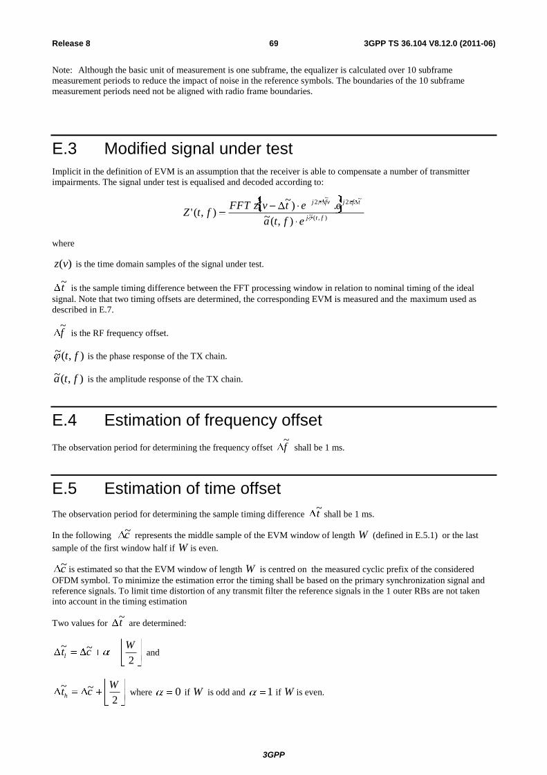
3GPP
3GPP TS 36.104 V8.12.0 (2011-06) 69 Release 8
Note: Although the basic unit of measurement is one subframe, the equalizer is calculated over 10 subframe
measurement periods to reduce the impact of noise in the reference symbols. The boundaries of the 10 subframe
measurement periods need not be aligned with radio frame boundaries.
E.3 Modified signal under test
Implicit in the definition of EVM is an assumption that the receiver is able to compensate a number of transmitter
impairments. The signal under test is equalised and decoded according to:
),(~
~2
~2
),(~.)
~(
),('ftj
tfjvfj
efta
eetvzFFTftZ
where
)(vz is the time domain samples of the signal under test.
t~
is the sample timing difference between the FFT processing window in relation to nominal timing of the ideal
signal. Note that two timing offsets are determined, the corresponding EVM is measured and the maximum used as
described in E.7.
f~
is the RF frequency offset.
),(~ ft is the phase response of the TX chain.
),(~ fta is the amplitude response of the TX chain.
E.4 Estimation of frequency offset
The observation period for determining the frequency offset f~
shall be 1 ms.
E.5 Estimation of time offset
The observation period for determining the sample timing difference t~
shall be 1 ms.
In the following c~ represents the middle sample of the EVM window of length W (defined in E.5.1) or the last
sample of the first window half if W is even.
c~ is estimated so that the EVM window of length W is centred on the measured cyclic prefix of the considered
OFDM symbol. To minimize the estimation error the timing shall be based on the primary synchronization signal and
reference signals. To limit time distortion of any transmit filter the reference signals in the 1 outer RBs are not taken
into account in the timing estimation
Two values for t~
are determined:
2
~~ Wctl and
2
~~ Wcth where 0 if W is odd and 1 if W is even.
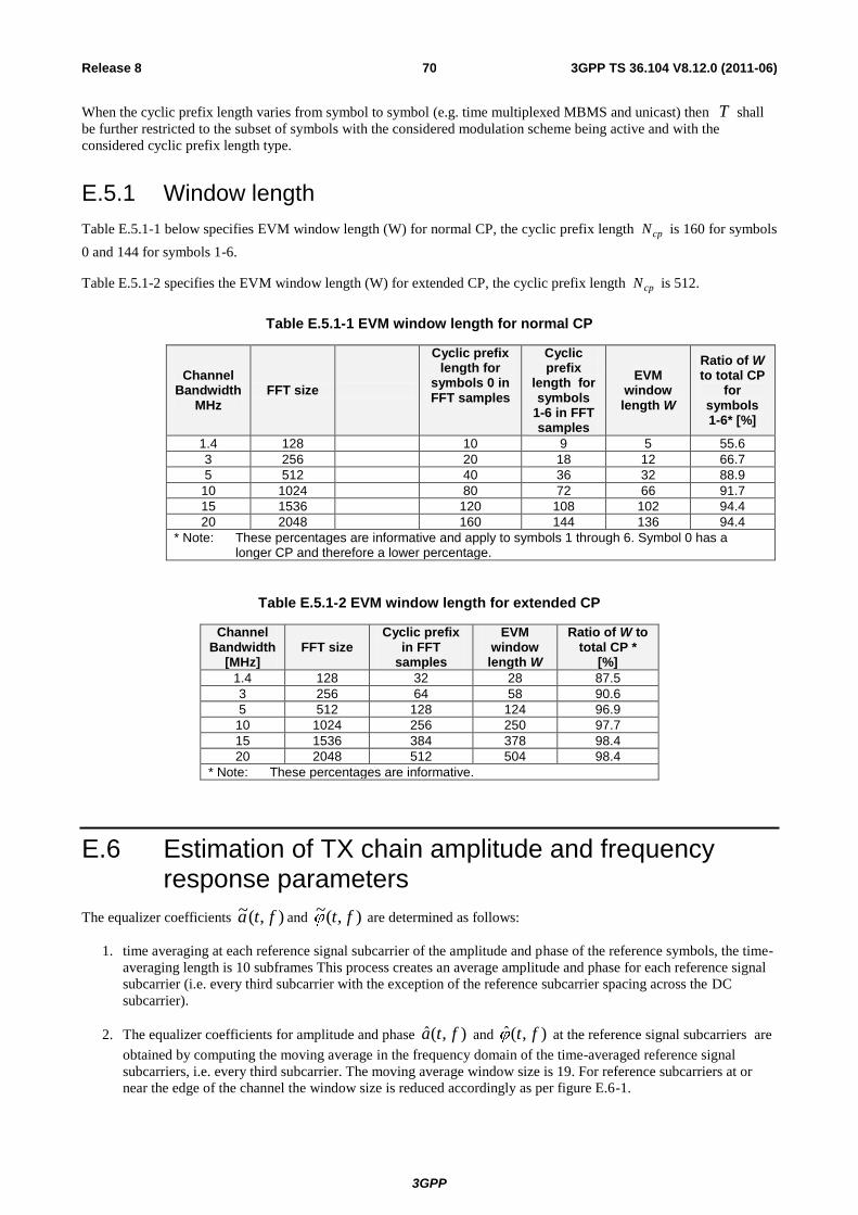
3GPP
3GPP TS 36.104 V8.12.0 (2011-06) 70 Release 8
When the cyclic prefix length varies from symbol to symbol (e.g. time multiplexed MBMS and unicast) then T shall
be further restricted to the subset of symbols with the considered modulation scheme being active and with the
considered cyclic prefix length type.
E.5.1 Window length
Table E.5.1-1 below specifies EVM window length (W) for normal CP, the cyclic prefix length cpN is 160 for symbols
0 and 144 for symbols 1-6.
Table E.5.1-2 specifies the EVM window length (W) for extended CP, the cyclic prefix length cpN is 512.
Table E.5.1-1 EVM window length for normal CP
Channel Bandwidth
MHz FFT size
Cyclic prefix length for
symbols 0 in FFT samples
Cyclic prefix
length for symbols
1-6 in FFT samples
EVM window length W
Ratio of W to total CP
for symbols 1-6* [%]
1.4 128 10 9 5 55.6
3 256 20 18 12 66.7
5 512 40 36 32 88.9
10 1024 80 72 66 91.7
15 1536 120 108 102 94.4
20 2048 160 144 136 94.4
* Note: These percentages are informative and apply to symbols 1 through 6. Symbol 0 has a longer CP and therefore a lower percentage.
Table E.5.1-2 EVM window length for extended CP
Channel Bandwidth
[MHz] FFT size
Cyclic prefix in FFT
samples
EVM window length W
Ratio of W to total CP *
[%]
1.4 128 32 28 87.5
3 256 64 58 90.6
5 512 128 124 96.9
10 1024 256 250 97.7
15 1536 384 378 98.4
20 2048 512 504 98.4
* Note: These percentages are informative.
E.6 Estimation of TX chain amplitude and frequency response parameters
The equalizer coefficients ),(~ fta and ),(~ ft are determined as follows:
1. time averaging at each reference signal subcarrier of the amplitude and phase of the reference symbols, the time-
averaging length is 10 subframes This process creates an average amplitude and phase for each reference signal
subcarrier (i.e. every third subcarrier with the exception of the reference subcarrier spacing across the DC
subcarrier).
2. The equalizer coefficients for amplitude and phase ),(ˆ fta and ),(ˆ ft at the reference signal subcarriers are
obtained by computing the moving average in the frequency domain of the time-averaged reference signal
subcarriers, i.e. every third subcarrier. The moving average window size is 19. For reference subcarriers at or
near the edge of the channel the window size is reduced accordingly as per figure E.6-1.
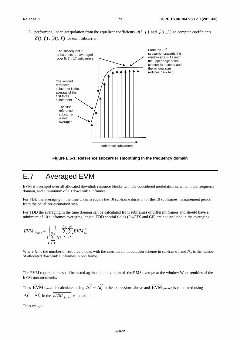
3GPP
3GPP TS 36.104 V8.12.0 (2011-06) 71 Release 8
3. performing linear interpolation from the equalizer coefficients ),(ˆ fta and ),(ˆ ft to compute coefficients
),(~ fta , ),(~ ft for each subcarrier.
The subsequent 7 subcarriers are averaged over 5, 7 .. 17 subcarriers
From the 10th
subcarrier onwards the window size is 19 until the upper edge of the channel is reached and the window size reduces back to 1
The first reference subcarrier is not averaged
The second reference subcarrier is the average of the first three subcarriers
Reference subcarriers
Figure E.6-1: Reference subcarrier smoothing in the frequency domain
E.7 Averaged EVM
EVM is averaged over all allocated downlink resource blocks with the considered modulation scheme in the frequency
domain, and a minimum of 10 downlink subframes:
For FDD the averaging in the time domain equals the 10 subframe duration of the 10 subframes measurement period
from the equalizer estimation step.
For TDD the averaging in the time domain can be calculated from subframes of different frames and should have a
minimum of 10 subframes averaging length. TDD special fields (DwPTS and GP) are not included in the averaging.
dl
dl
N
i
Ni
j
jiN
i
frame EVM
Ni
EVM1 1
2
,
1
1
Where Ni is the number of resource blocks with the considered modulation scheme in subframe i and Ndl is the number
of allocated downlink subframes in one frame.
The EVM requirements shall be tested against the maximum of the RMS average at the window W extremities of the
EVM measurements:
Thus l frame,EVM is calculated using ltt~~
in the expressions above and hframe,EVM is calculated using
htt~~
in the frameEVM calculation.
Thus we get:
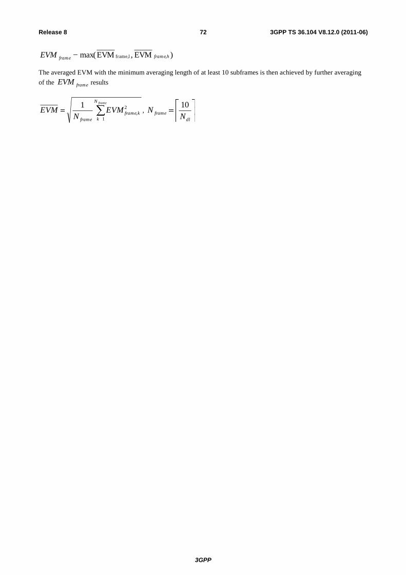
3GPP
3GPP TS 36.104 V8.12.0 (2011-06) 72 Release 8
)EVM ,EVMmax( ,l frame, hframeframeEVM
The averaged EVM with the minimum averaging length of at least 10 subframes is then achieved by further averaging
of the frameEVM results
frameN
k
kframe
frame
EVMN
EVM1
2
,
1,
dl
frameN
N10
3GPP
3GPP TS 36.104 V8.12.0 (2011-06) 73 Release 8
Annex F (Informative): Unwanted emission requirements for multi-carrier BS
F.1 General
In subclause 6.6, unwanted emission requirements for single carrier or multi-carrier BS are specified. This multi-carrier
BS corresponds to a multi-carrier BS of the same channel bandwidth for E-UTRA. The following two pragmatic
scenarios are considered in this annex:
- multi-carrier BS of different E-UTRA channel bandwidths, covering only 5 MHz and higher channel bandwidths
- multi-carrier BS of E-UTRA and UTRA, covering only 5 MHz and higher E-UTRA channel bandwidths.
All scenarios for channel bandwidths less than 5 MHz are for further study. The guidelines below assumes that the
power spectral density of the multiple carriers is the same. All other combinations of multiple carriers are ffs.
Note 1: Further information and analysis for these scenarios can be found in TR 36.942 [9].
F.2 Multi-carrier BS of different E-UTRA channel bandwidths
For a multi-carrier E-UTRA BS transmitting a group of carriers of different channel bandwidths (≥5 MHz), the channel
bandwidth of the outermost carriers should be considered for ACLR and Operating band unwanted emission
requirements. That is, the corresponding requirements for the channel bandwidth of each of the outermost carriers
should be applied at the respective side of the group of transmitted carriers.
F.3 Multi-carrier BS of E-UTRA and UTRA
For a multi-carrier BS transmitting a group of carriers of E-UTRA and UTRA (channel bandwidth(s) ≥5 MHz), the RAT
being used on the outermost carriers should be considered for ACLR and Operating band unwanted emission
requirements. That is, the corresponding requirements for the RAT being used on each of the outermost carriers should
be applied at the respective side of the group of transmitted carriers.
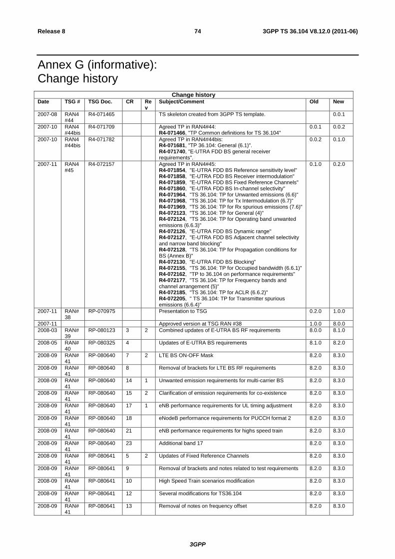
3GPP
3GPP TS 36.104 V8.12.0 (2011-06) 74 Release 8
Annex G (informative): Change history
Change history
Date TSG # TSG Doc. CR Rev
Subject/Comment Old New
2007-08 RAN4#44
R4-071465 TS skeleton created from 3GPP TS template. 0.0.1
2007-10 RAN4#44bis
R4-071709 Agreed TP in RAN4#44: R4-071466, "TP Common definitions for TS 36.104"
0.0.1 0.0.2
2007-10 RAN4#44bis
R4-071782 Agreed TP in RAN4#44bis: R4-071681, "TP 36.104: General (6.1)". R4-071740, "E-UTRA FDD BS general receiver requirements".
0.0.2 0.1.0
2007-11 RAN4#45
R4-072157 Agreed TP in RAN4#45: R4-071854, "E-UTRA FDD BS Reference sensitivity level" R4-071858, "E-UTRA FDD BS Receiver intermodulation" R4-071859, "E-UTRA FDD BS Fixed Reference Channels" R4-071860, "E-UTRA FDD BS In-channel selectivity" R4-071964, "TS 36.104: TP for Unwanted emissions (6.6)" R4-071968, "TS 36.104: TP for Tx Intermodulation (6.7)" R4-071969, "TS 36.104: TP for Rx spurious emissions (7.6)" R4-072123, "TS 36.104: TP for General (4)" R4-072124, "TS 36.104: TP for Operating band unwanted emissions (6.6.3)" R4-072126, "E-UTRA FDD BS Dynamic range" R4-072127, "E-UTRA FDD BS Adjacent channel selectivity and narrow band blocking" R4-072128, "TS 36.104: TP for Propagation conditions for BS (Annex B)" R4-072130, "E-UTRA FDD BS Blocking" R4-072155, "TS 36.104: TP for Occupied bandwidth (6.6.1)" R4-072162, "TP to 36.104 on performance requirements" R4-072177, "TS 36.104: TP for Frequency bands and channel arrangement (5)" R4-072185, "TS 36.104: TP for ACLR (6.6.2)" R4-072205, " TS 36.104: TP for Transmitter spurious emissions (6.6.4)"
0.1.0 0.2.0
2007-11 RAN#38
RP-070975 Presentation to TSG 0.2.0 1.0.0
2007-11 Approved version at TSG RAN #38 1.0.0 8.0.0
2008-03 RAN#39
RP-080123 3 2 Combined updates of E-UTRA BS RF requirements 8.0.0 8.1.0
2008-05 RAN#40
RP-080325 4 Updates of E-UTRA BS requirements 8.1.0 8.2.0
2008-09 RAN#41
RP-080640 7 2 LTE BS ON-OFF Mask 8.2.0 8.3.0
2008-09 RAN#41
RP-080640 8 Removal of brackets for LTE BS RF requirements 8.2.0 8.3.0
2008-09 RAN#41
RP-080640 14 1 Unwanted emission requirements for multi-carrier BS 8.2.0 8.3.0
2008-09 RAN#41
RP-080640 15 2 Clarification of emission requirements for co-existence 8.2.0 8.3.0
2008-09 RAN#41
RP-080640 17 1 eNB performance requirements for UL timing adjustment 8.2.0 8.3.0
2008-09 RAN#41
RP-080640 18 eNodeB performance requirements for PUCCH format 2 8.2.0 8.3.0
2008-09 RAN#41
RP-080640 21 eNB performance requirements for highs speed train 8.2.0 8.3.0
2008-09 RAN#41
RP-080640 23 Additional band 17 8.2.0 8.3.0
2008-09 RAN#41
RP-080641 5 2 Updates of Fixed Reference Channels 8.2.0 8.3.0
2008-09 RAN#41
RP-080641 9 Removal of brackets and notes related to test requirements 8.2.0 8.3.0
2008-09 RAN#41
RP-080641 10 High Speed Train scenarios modification 8.2.0 8.3.0
2008-09 RAN#41
RP-080641 12 Several modifications for TS36.104 8.2.0 8.3.0
2008-09 RAN#41
RP-080641 13 Removal of notes on frequency offset 8.2.0 8.3.0
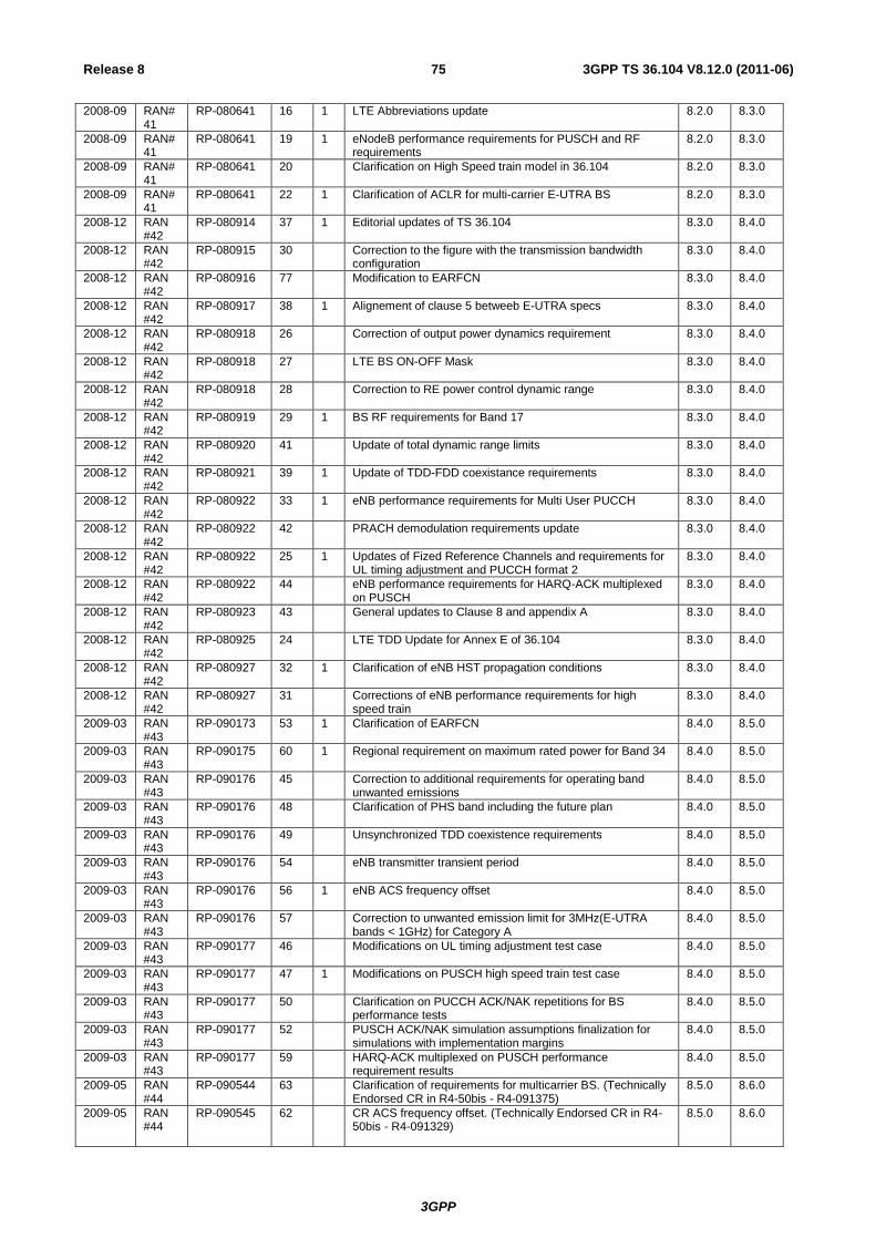
3GPP
3GPP TS 36.104 V8.12.0 (2011-06) 75 Release 8
2008-09 RAN#41
RP-080641 16 1 LTE Abbreviations update 8.2.0 8.3.0
2008-09 RAN#41
RP-080641 19 1 eNodeB performance requirements for PUSCH and RF requirements
8.2.0 8.3.0
2008-09 RAN#41
RP-080641 20 Clarification on High Speed train model in 36.104 8.2.0 8.3.0
2008-09 RAN#41
RP-080641 22 1 Clarification of ACLR for multi-carrier E-UTRA BS 8.2.0 8.3.0
2008-12 RAN #42
RP-080914 37 1 Editorial updates of TS 36.104 8.3.0 8.4.0
2008-12 RAN #42
RP-080915 30 Correction to the figure with the transmission bandwidth configuration
8.3.0 8.4.0
2008-12 RAN #42
RP-080916 77 Modification to EARFCN 8.3.0 8.4.0
2008-12 RAN #42
RP-080917 38 1 Alignement of clause 5 betweeb E-UTRA specs 8.3.0 8.4.0
2008-12 RAN #42
RP-080918 26 Correction of output power dynamics requirement 8.3.0 8.4.0
2008-12 RAN #42
RP-080918 27 LTE BS ON-OFF Mask 8.3.0 8.4.0
2008-12 RAN #42
RP-080918 28 Correction to RE power control dynamic range 8.3.0 8.4.0
2008-12 RAN #42
RP-080919 29 1 BS RF requirements for Band 17 8.3.0 8.4.0
2008-12 RAN #42
RP-080920 41 Update of total dynamic range limits 8.3.0 8.4.0
2008-12 RAN #42
RP-080921 39 1 Update of TDD-FDD coexistance requirements 8.3.0 8.4.0
2008-12 RAN #42
RP-080922 33 1 eNB performance requirements for Multi User PUCCH 8.3.0 8.4.0
2008-12 RAN #42
RP-080922 42 PRACH demodulation requirements update 8.3.0 8.4.0
2008-12 RAN #42
RP-080922 25 1 Updates of Fized Reference Channels and requirements for UL timing adjustment and PUCCH format 2
8.3.0 8.4.0
2008-12 RAN #42
RP-080922 44 eNB performance requirements for HARQ-ACK multiplexed on PUSCH
8.3.0 8.4.0
2008-12 RAN #42
RP-080923 43 General updates to Clause 8 and appendix A 8.3.0 8.4.0
2008-12 RAN #42
RP-080925 24 LTE TDD Update for Annex E of 36.104 8.3.0 8.4.0
2008-12 RAN #42
RP-080927 32 1 Clarification of eNB HST propagation conditions 8.3.0 8.4.0
2008-12 RAN #42
RP-080927 31 Corrections of eNB performance requirements for high speed train
8.3.0 8.4.0
2009-03 RAN #43
RP-090173 53 1 Clarification of EARFCN 8.4.0 8.5.0
2009-03 RAN #43
RP-090175 60 1 Regional requirement on maximum rated power for Band 34 8.4.0 8.5.0
2009-03 RAN #43
RP-090176 45 Correction to additional requirements for operating band unwanted emissions
8.4.0 8.5.0
2009-03 RAN #43
RP-090176 48 Clarification of PHS band including the future plan 8.4.0 8.5.0
2009-03 RAN #43
RP-090176 49 Unsynchronized TDD coexistence requirements 8.4.0 8.5.0
2009-03 RAN #43
RP-090176 54 eNB transmitter transient period 8.4.0 8.5.0
2009-03 RAN #43
RP-090176 56 1 eNB ACS frequency offset 8.4.0 8.5.0
2009-03 RAN #43
RP-090176 57 Correction to unwanted emission limit for 3MHz(E-UTRA bands < 1GHz) for Category A
8.4.0 8.5.0
2009-03 RAN #43
RP-090177 46 Modifications on UL timing adjustment test case 8.4.0 8.5.0
2009-03 RAN #43
RP-090177 47 1 Modifications on PUSCH high speed train test case 8.4.0 8.5.0
2009-03 RAN #43
RP-090177 50 Clarification on PUCCH ACK/NAK repetitions for BS performance tests
8.4.0 8.5.0
2009-03 RAN #43
RP-090177 52 PUSCH ACK/NAK simulation assumptions finalization for simulations with implementation margins
8.4.0 8.5.0
2009-03 RAN #43
RP-090177 59 HARQ-ACK multiplexed on PUSCH performance requirement results
8.4.0 8.5.0
2009-05 RAN #44
RP-090544 63 Clarification of requirements for multicarrier BS. (Technically Endorsed CR in R4-50bis - R4-091375)
8.5.0 8.6.0
2009-05 RAN #44
RP-090545 62 CR ACS frequency offset. (Technically Endorsed CR in R4-50bis - R4-091329)
8.5.0 8.6.0
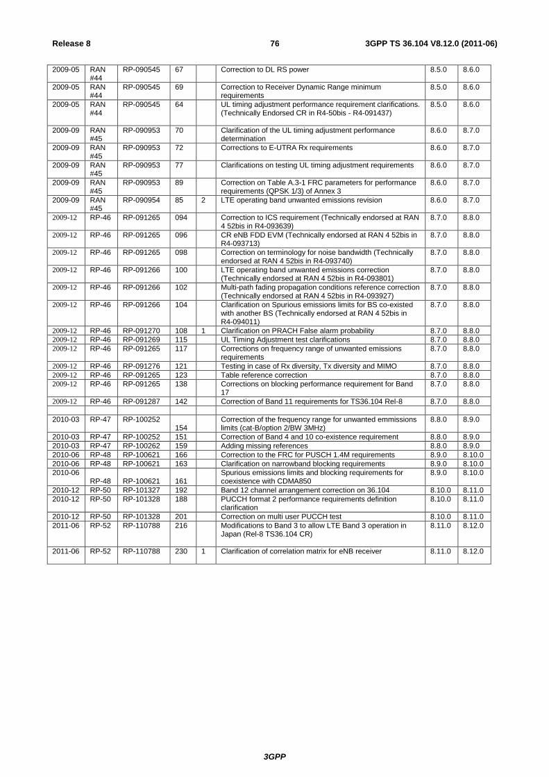
3GPP
3GPP TS 36.104 V8.12.0 (2011-06) 76 Release 8
2009-05 RAN #44
RP-090545 67 Correction to DL RS power 8.5.0 8.6.0
2009-05 RAN #44
RP-090545 69 Correction to Receiver Dynamic Range minimum requirements
8.5.0 8.6.0
2009-05 RAN #44
RP-090545 64 UL timing adjustment performance requirement clarifications. (Technically Endorsed CR in R4-50bis - R4-091437)
8.5.0 8.6.0
2009-09 RAN #45
RP-090953 70 Clarification of the UL timing adjustment performance determination
8.6.0 8.7.0
2009-09 RAN #45
RP-090953 72 Corrections to E-UTRA Rx requirements 8.6.0 8.7.0
2009-09 RAN #45
RP-090953 77 Clarifications on testing UL timing adjustment requirements 8.6.0 8.7.0
2009-09 RAN #45
RP-090953 89 Correction on Table A.3-1 FRC parameters for performance requirements (QPSK 1/3) of Annex 3
8.6.0 8.7.0
2009-09 RAN #45
RP-090954 85 2 LTE operating band unwanted emissions revision 8.6.0 8.7.0
2009-12 RP-46 RP-091265 094 Correction to ICS requirement (Technically endorsed at RAN 4 52bis in R4-093639)
8.7.0 8.8.0
2009-12 RP-46 RP-091265 096 CR eNB FDD EVM (Technically endorsed at RAN 4 52bis in R4-093713)
8.7.0 8.8.0
2009-12 RP-46 RP-091265 098 Correction on terminology for noise bandwidth (Technically endorsed at RAN 4 52bis in R4-093740)
8.7.0 8.8.0
2009-12 RP-46 RP-091266 100 LTE operating band unwanted emissions correction (Technically endorsed at RAN 4 52bis in R4-093801)
8.7.0 8.8.0
2009-12 RP-46 RP-091266 102 Multi-path fading propagation conditions reference correction (Technically endorsed at RAN 4 52bis in R4-093927)
8.7.0 8.8.0
2009-12 RP-46 RP-091266 104 Clarification on Spurious emissions limits for BS co-existed with another BS (Technically endorsed at RAN 4 52bis in R4-094011)
8.7.0 8.8.0
2009-12 RP-46 RP-091270 108 1 Clarification on PRACH False alarm probability 8.7.0 8.8.0 2009-12 RP-46 RP-091269 115 UL Timing Adjustment test clarifications 8.7.0 8.8.0 2009-12 RP-46 RP-091265 117 Corrections on frequency range of unwanted emissions
requirements 8.7.0 8.8.0
2009-12 RP-46 RP-091276 121 Testing in case of Rx diversity, Tx diversity and MIMO 8.7.0 8.8.0 2009-12 RP-46 RP-091265 123 Table reference correction 8.7.0 8.8.0 2009-12 RP-46 RP-091265 138 Corrections on blocking performance requirement for Band
17 8.7.0 8.8.0
2009-12 RP-46 RP-091287 142 Correction of Band 11 requirements for TS36.104 Rel-8 8.7.0 8.8.0
2010-03 RP-47 RP-100252 154
Correction of the frequency range for unwanted emmissions limits (cat-B/option 2/BW 3MHz)
8.8.0 8.9.0
2010-03 RP-47 RP-100252 151 Correction of Band 4 and 10 co-existence requirement 8.8.0 8.9.0
2010-03 RP-47 RP-100262 159 Adding missing references 8.8.0 8.9.0
2010-06 RP-48 RP-100621 166 Correction to the FRC for PUSCH 1.4M requirements 8.9.0 8.10.0
2010-06 RP-48 RP-100621 163 Clarification on narrowband blocking requirements 8.9.0 8.10.0
2010-06 RP-48 RP-100621 161
Spurious emissions limits and blocking requirements for coexistence with CDMA850
8.9.0 8.10.0
2010-12 RP-50 RP-101327 192 Band 12 channel arrangement correction on 36.104 8.10.0 8.11.0
2010-12 RP-50 RP-101328 188 PUCCH format 2 performance requirements definition clarification
8.10.0 8.11.0
2010-12 RP-50 RP-101328 201 Correction on multi user PUCCH test 8.10.0 8.11.0
2011-06 RP-52 RP-110788 216 Modifications to Band 3 to allow LTE Band 3 operation in Japan (Rel-8 TS36.104 CR)
8.11.0 8.12.0
2011-06 RP-52 RP-110788 230 1 Clarification of correlation matrix for eNB receiver 8.11.0 8.12.0