ares i flight control system overview - nasa · ares i flight control system overview charles hall,...
TRANSCRIPT

American Institute of Aeronautics and Astronautics1
Ares I Flight Control System Overview
Charles Hall, Chong Lee, Mark Jackson, Mark Whorton, Mark West1
NASA Marshall Space Flight Center, Huntsville, AL 35812
Jay Brandon2
NASA Langley Research Center, Hampton, VA 23681
Rob A. Hall, Jimmy Jang, Naz Bedrossian3
The Charles Stark Draper Laboratory, Inc.
Jimmy Compton4
Dynamic Concepts, Inc.
Chad Rutherford5
BD Systems, Inc.
This paper describes the control challenges posed by the Ares I vehicle, the flight controlsystem design and performance analyses used to test and verify the design. The majorchallenges in developing the control system are structural dynamics, dynamic effects fromthe powerful first stage booster, aerodynamics, first stage separation and large uncertaintiesin the dynamic models for all these. Classical control techniques were employed usinginnovative methods for structural mode filter design and an anti-drift feature to compensatefor translational and rotational disturbances. This design was coded into an integratedvehicle flight simulation and tested by Monte Carlo methods. The product of this effort is alinear, robust controller design that is easy to implement, verify and test.
I. IntroductionThe Ares I vehicle stack consists of a modified, Shuttle heritage first stage Solid Rocket Booster (SRB), a new
upper stage to be developed in-house at the Marshall Space Flight Center, the service and crew modules (Orion) anda Launch Abort System solid motor extending from the top of the crew module. On the pad, the vehicle iscomparable in height to the Saturn V launch vehicle, but much more slender. Characteristic of such a design are lowstructural mode frequencies that require special attention when designing bending filters for the control system. Thisis not an uncommon problem in launch vehicle control system design, but challenging nonetheless especially whenthe control designers job is not only to keep the vehicle stable in flight, but provide accurate guidance commandtracking so the proper orbit insertion target can be reached.
While the first stage SRB has been employed for years on the Space Shuttle, its higher thrust derivative appliedas the first stage for an in-line launch vehicle such as Ares I highlights interesting dynamic effects not consideredvery significant for Shuttle flight control. When the nozzle is gimbaled from the null position, the thrust may not bedirected perfectly along the geometric center of the nozzle and the effective gimbal center may be offset from thecenterline of the booster by a small amount causing roll, pitch and yaw torques that must be compensated for by thecontrol system. These effects were known to exist for the Shuttle SRB but their influence is minimal since theShuttle stack employs two boosters in parallel and has three liquid engines as well to counter such disturbancetorques.
1 Aerospace Engineers, Flight Mechanics and Analysis Division/EV40, Huntsville, AL 35812.2 Aerospace Engineer, /RTD-Flight Dynamics, Hampton, VA . 236813 Aerospace Engineers, /,4 Aerospace Engineer, /,5 Aerospace Engineer, /,
https://ntrs.nasa.gov/search.jsp?R=20080048228 2018-09-30T22:09:32+00:00Z

American Institute of Aeronautics and Astronautics2
The first stage Roll Control System (RoCS) had to be designed to deal with thrust vector and aerodynamicdisturbance torques while providing steering torque for roll maneuvers commanded by guidance. The upper stagereaction control system (ReCS) has to deal with large attitude errors and rates after first stage separation. After theupper stage engine cuts off, three axis control is provided by the ReCS to damp roll pitch and yaw body rates untilOrion separates. These effects had to be considered in the design of the phase planes to provide adequate rollattitude orientation and rate damping while conserving propellant.
The design philosophy for the Ares I flight control system (FCS) was to draw from previous flight experience toestablish a control architecture to begin with, then modify as needed to address vehicle and mission specificrequirements and design goals. Studying Saturn/Apollo vehicles and control systems revealed that the first bendingmode frequency was not far from that of Ares I, which led to adopting a proportional-integral-derivative control lawwith serial bending filters to phase stabilize the first bending mode. Consultation with private industry launchproviders led to investigating the use of distributed rate gyros to increase robustness of the control system to vehiclebending during high dynamic pressure regions of flight. Load relief systems from Saturn and Shuttle were analyzedand tested in simulations of the Ares I, as well as a new anti drift channel to increase robustness to force and torquedisturbances such as those caused by wind and thrust vector misalignment. Shuttle experience led to thedevelopment of an efficient phase plane controller for the RoCs and ReCS. Rigorous stability analyses and flightsimulations have shown that the current FCS design has proven to be robust to large system dispersions and vehicledesign uncertainties.
II. Vehicle DescriptionFigure 1 shows and expanded view of Ares I. The first stage is a single, recoverable solid rocket booster
developing roughly 3.5 million pounds of peak thrust at about 83 thousand feet for a nominal mission. It will useShuttle SRB heritage TVC actuators. A redundant Rate Gyro Unit (RGA) housed in the aft skirt is used for flightcontrol. Roll control for first stage is managed by the RoCS mounted in two external pods on the interstage, whichalso houses a second RGA package used for flight control. The upper stage is powered by a single liquid propellantengine, the J-2X, that develops 294,000 lbf vacuum thrust. The upper stage ReCS, providing roll, pitch and yawcontrol, is located in two external pods on the aft end of the upper stage. The Inertial Measurement Units (IMU) andflight computers used for guidance, navigation and control are located in the instrument unit at the top of the upperstage.
Figure 1: The Ares I Launch Vehicle.

American Institute of Aeronautics and Astronautics3
III. Flight Control System DescriptionThe FCS uses a Thrust Vector Control (TVC) system consisting of two actuators located 90 degrees apart that
position the first and second stage nozzles for pitch and yaw control. Roll control for powered flight is provided bytwo separate systems of thrusters located in two pods, 180 degrees apart, on the interstage and on the upper stage.The upper stage thrusters also provide roll, pitch and yaw rate damping after the upper stage engine cuts off. TheIMU provides an attitude quaternion and body rates to the FCS. Pitch and yaw body rates are also obtained from theRGU packages located forward in the interstage and aft in the SRB skirt. The control algorithms for first and secondstage flight are identical, except for the three axis capability of the ReCS for post-MECO coast.
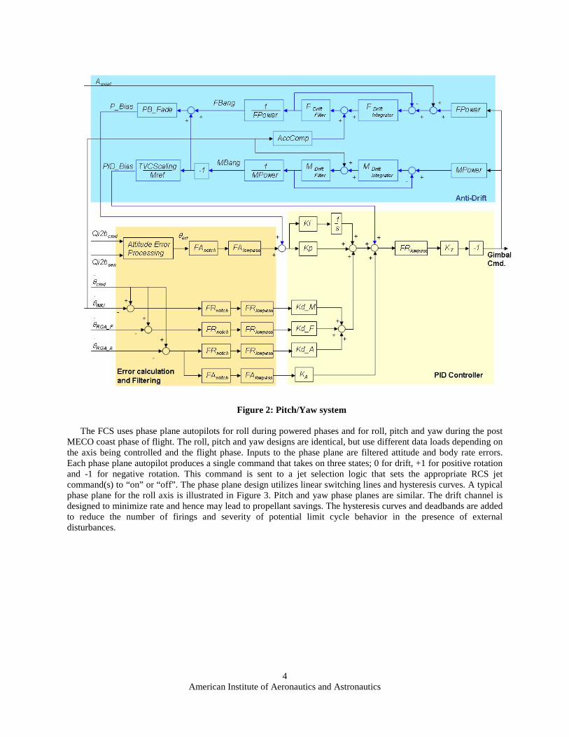
A block diagram of the pitch/yaw control system is shown in Figure 2. Pitch and yaw control channels areidentical thanks to vehicle symmetry, with one producing a gimbal command in the pitch body axis and the other inthe yaw body axis. These signals are then sent to a mixing and limiting logic (not shown) that provides command tothe TVC actuators. Guidance provides steering commands in the form of a command quaternion which the FCScombines with the vehicle attitude quaternion to obtain roll, pitch and yaw attitude errors. Guidance also providesangular rate commands that are summed with sensed body rates to form rate errors. Sensed body rates and axialacceleration are provided by the IMU. The forward and aft RGA packages provide pitch and yaw body rates only.
The error signals are filtered in two stages, first with a notch filter then with a low pass filter. These filtersprovide the necessary phase and gain shaping required to stabilize the bending modes. After filtering the rate errors,the signals are gained and summed in such a way as to blend the forward and aft signals to reduce bending modeamplification of the rate signals due to structural bending. More discussion on filter design and sensor placementwill be discussed in § IV, Stability Analysis. The filtered and gained error signals are sent to a proportional-integral-derivative (PID) control law designed to provide the proper bandwidth as well as good transient and steady stateresponses. This signal is filtered again with a low pass filter after inputs from the anti-drift channel are added.Finally, a loop gain is applied and the signal is negated for proper polarity to obtain the final gimbal command.
The anti-drift (AD) algorithm includes force and moment balances using input data from rate gyros andaccelerometers. The AD design maintains the same response to control as the normal PID control system, and haslittle effect on the PID control gain and phase margins. Signals from the AD algorithm augment those from the PIDalgorithm to help reduce translational drift from the trajectory due to wind, TVC biases, and center of gravity (CG)offsets. Two outputs come from the AD block – an angle bias term, and a PID bias term. The angle bias term is usedto align the thrust vector in a direction to balance external forces, and the PID bias term is an input used to balanceexternal moments. The external forces and moments could be caused by aerodynamics, TVC offsets, gusts, winds,etc. The actual implementation includes some low-pass filtering to keep noise from causing undesired results, and tokeep the response frequencies of the AD low to avoid coupling with the structural vibrations. Additionally, since theaccelerometer data is from the IMU – which may have a radial offset from the centerline of the vehicle and not atthe axial CG location, corrections to the acceleration signals are made due to body angular rates. The AD and PIDcontrol laws require scheduled gains that are related to thrust, inertia, CG location, and weight.
American Institute of Aeronautics and Astronautics4
Figure 2: Pitch/Yaw system
The FCS uses phase plane autopilots for roll during powered phases and for roll, pitch and yaw during the postMECO coast phase of flight. The roll, pitch and yaw designs are identical, but use different data loads depending onthe axis being controlled and the flight phase. Inputs to the phase plane are filtered attitude and body rate errors.Each phase plane autopilot produces a single command that takes on three states; 0 for drift, +1 for positive rotationand -1 for negative rotation. This command is sent to a jet selection logic that sets the appropriate RCS jetcommand(s) to “on” or “off”. The phase plane design utilizes linear switching lines and hysteresis curves. A typicalphase plane for the roll axis is illustrated in Figure 3. Pitch and yaw phase planes are similar. The drift channel isdesigned to minimize rate and hence may lead to propellant savings. The hysteresis curves and deadbands are addedto reduce the number of firings and severity of potential limit cycle behavior in the presence of externaldisturbances.

American Institute of Aeronautics and Astronautics5
Figure 3: Phase plane controller.
IV. Stability AnalysisStability analyses were conducted in two stages, the first for the purpose of filter design and an initial assessment
of control system robustness, and the second in a Monte Carlo analysis where all system dispersions are applied.Both analyses must meet stability margin requirements in gain and phase before the design is accepted for rigorousflight performance analysis in the time domain.
The filter design methodology was based on a numerical constrained optimization approach to maximizeperformance. The design parameters are the coefficients of bending filters. A set of feasible parameters must satisfythe following constraints:
1. The filter itself must be stable and minimum phase to guarantee stability and performance.2. The bandwidth of the bending filter should be greater than that of the PID controller to avoid rigid
performance degradation.These constraints can be used to set the upper and lower bounds for the design parameters3.Multiple rate sensors are used along the structure to allow for the blending of the sensed rotational rate, and
hence active removal of flex dynamics in the rate channel4. Design of the rate gyro blending control law has twokey control considerations:
1. The phase of the first bending mode must be well understood since the first mode is phase stabilized.2. The gyro blending will aid in gain stabilization of the higher bending mode dynamics by flex rate
cancellation.For first mode phase stabilization, the sensor weighting is designed such that the upper stage sensors dominate
the control law input, hence the first bending mode must be significantly lagged by the filtering to compensate forthe sensors being non-collocated with the actuator. Specifically, the upper stage rate gyro is heavily weighted whenblending with the first stage rate gyro. These blending weights are designed to significantly remove second modeflex intrusion, while robustly preserving the phase stabilization on the first flex mode.

American Institute of Aeronautics and Astronautics6
An example of first stage stability analysis results are shown in the Nichols plot shown in Figure 4. Secondstage is less challenging due to higher bending modes and the absence of aerodynamics, so only first stage resultswill be shown. In this analysis, robustness of the pitch channel filter designed is examined. The first bending modefrequency was dispersed ± 10% and all higher modal frequencies were dispersed ± 30%. Stability marginrequirements are depicted as diamonds at the Nyquist points, where the black diamonds represent the dispersedrequirements of ± 6 dB gain and 20 degrees phase and the magenta diamonds represent the nominal requirements of± 6 dB gain and 30 degrees phase. Frequency response curves at 10 second intervals are shown, with lowestfrequency on each curve at the upper right part of the plot and highest frequencies at the lower left. It can be seenthat low frequency margins, where aerodynamics and propellant slosh are important, are being met. Although thefirst bending mode can have significant gain, it is phase stable while all the higher frequency modes are gain stablewith ample margin.
Figure 4: First stage Nichols plot with modal dispersions.
In the next phase of stability analysis, all system dispersions are applied that include not only bending modedispersions, but dispersed aerodynamics, propulsion system, environment (wind), mass properties and sensors. Anexample of first stage margins are shown in Table 1.
Table 1. Dispersed stability margins for first stage flight.
ISS TrajectoryMargin 1 Sec 22 Sec 30 Sec 42 Sec 60 Sec
Pitch Low Frequency GM 13.9 12.6 10.7 8.7 6.4Pitch High Frequency GM 9.7 9.8 10.2 10.2 8.8Pitch First Flex Mode GM 20.0 55.3 54.6 58.6 20.0
Pitch Low Frequency PM 32.0 40.0 40.3 40.3 33.7Pitch First Flex Mode PM 55.8 59.0 60.9 61.8 57.2
Yaw Low Frequency GM 13.9 12.6 10.7 8.8 6.3Yaw High Frequency GM 9.7 9.8 10.3 10.2 8.8Yaw First Flex Mode GM 20.1 55.3 54.8 56.9 20.4
Yaw Low Frequency PM 36.2 40.0 40.2 40.0 33.7

American Institute of Aeronautics and Astronautics7
Yaw First Flex Mode PM 55.7 58.9 60.8 61.6 57.1
Margin 85 Sec 105 Sec 110 Sec 118 Sec 120 SecPitch Low Frequency GM 9.4 13.9 18.2 16.8 13.8Pitch High Frequency GM 9.1 8.8 8.0 14.0 17.3Pitch First Flex Mode GM 24.0 26.4 28.4 36.8 40.2
Pitch Low Frequency PM 34.7 33.6 36.2 43.8 42.6Pitch First Flex Mode PM 64.5 71.1 75.2 109.9 Inf
Yaw Low Frequency GM 9.4 13.9 18.1 16.8 13.8Yaw High Frequency GM 9.1 8.7 8.2 13.9 17.4Yaw First Flex Mode GM 23.7 26.1 28.1 36.9 40.3
Yaw Low Frequency PM 34.6 32.0 34.5 43.7 42.5Yaw First Flex Mode PM 64.3 71.1 74.2 109.9 Inf
V. Simulated Flight Performance AnalysisThe FCS algorithms are straightforward and easy to implement is a computer simulation. The flight simulation
code used for the Ares I project, MAVERIC (Marshal Aerospace VEhicle Representation In C) [], contains detailedvehicle, subsystem and environmental models and is used for single runs as well as large batches of runs for MonteCarlo analysis. At this stage of Ares I development, the vehicle design is evolving therefore math modelsrepresenting the vehicle have fairly large uncertainties associated with them. A description of the dispersions may befound in the reference5. Applying these large uncertainties along with known wind dispersions during the mostsevere months is a good test for control system robustness.
Ares I has two reference trajectories, one to carry crew and payload to an insertion target for the InternationalSpace Station (ISS) and the other is a space exploration trajectory referred to as the Due East (DE) trajectory. Sincemass estimates among the vehicle elements are still converging, to adequately cover all scenarios two differentvehicles have to be simulated; a heavy/slow vehicle and a light/fast vehicle. Certain months are known to bedemanding not only on the control system but on loads, heating rates and upper stage re-entry footprint. Thisculminated in nine different Monte Carlo cases, each having 2,000 individual simulations in order to capture threesigma dispersions with the required confidence level. To further test control system robustness, the gains and filterswere designed for only one mean reference trajectory and the nominal vehicle. Only one filter coefficient set for firststage and one set for second stage were used.
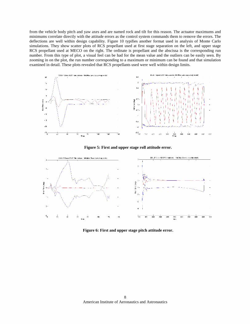
The dispersed simulations are analyzed to investigate many things, such as aerodynamic and thermal loads, massto orbit, insertion accuracy and control system performance to name a few. Some example control systemparameters are shown in figures 5 through 9 as envelope plots where the minimum and maximum values at eachtime point from all 2,000 simulations are shown as two continuous curves (blue), co-plotted with the same parameterfrom a nominal simulation (red curve). From these nine sets of Monte Carlo simulations, the most demanding onesfor the control system and its hardware were singled out. The largest roll attitude error (figure 5) occurs during theISS mission in August due to the large roll maneuver required concurrent with roll disturbances arising from thrustvector coupling and in this case, a hot, higher thrust SRB. The roll control system performs the roll maneuver andbrings the attitude back within the two degree dead band for the remainder of the flight. The pitch and yaw attitudeerrors show how wind disturbances during high dynamic pressure regions of flight can cause the vehicle to divergefrom it’s trajectory, although peak errors are very reasonable. First stage guidance is open loop and obtains steeringcommands from a table []. The guidance commands are derived from a gravity turn trajectory that steers the vehicleso that aerodynamic angles of attack and side slip are zero before maximum aerodynamic pressure (max Q) isreached. The control system follows this steering even in the face of wind and other disturbances and reliably bringsaerodynamic angles to small values just before max Q which occurs around 60 seconds. The only demanding partof second stage flight is right after first stage separation when the control system must remove attitude errors thatbuild during the SRB separation event. Guidance is closed loop during upper stage flight, and immediately begins tocommand the attitude and rates to steer to the required insertion target. TVC actuator gimbal angle envelope plotsfor first and upper stage flight are shown in Figures 8 and 9, respectively. The TVC actuators are skewed 90 degrees
American Institute of Aeronautics and Astronautics8
from the vehicle body pitch and yaw axes and are named rock and tilt for this reason. The actuator maximums andminimums correlate directly with the attitude errors as the control system commands them to remove the errors. Thedeflections are well within design capability. Figure 10 typifies another format used in analysis of Monte Carlosimulations. They show scatter plots of RCS propellant used at first stage separation on the left, and upper stageRCS propellant used at MECO on the right. The ordinate is propellant and the abscissa is the corresponding runnumber. From this type of plot, a visual feel can be had for the mean value and the outliers can be easily seen. Byzooming in on the plot, the run number corresponding to a maximum or minimum can be found and that simulationexamined in detail. These plots revealed that RCS propellants used were well within design limits.
Figure 5: First and upper stage roll attitude error.
Figure 6: First and upper stage pitch attitude error.

American Institute of Aeronautics and Astronautics9
Figure 7: First and upper stage yaw attitude error.
Figure 8: First stage rock and tilt gimbal angles.
Figure 9: Upper stage rock and tilt gimbal angles.

American Institute of Aeronautics and Astronautics10
Figure 10: First and upper stage RCS propellant scatter plots.
VI. ConclusionClassical control techniques, complimented by innovative bending filter design techniques and an anti-drift
feature have produced a robust linear control system for the Ares I launch vehicle that is easy to implement, verifyand test in flight simulations. Extensive stability analyses verify stability in the frequency domain while non-linear,high fidelity flight simulations verify good performance in the time domain. The design proved to be robust to verylarge dispersions in vehicle and environmental models, while using gain and filter sets designed for a single, meantrajectory and nominal vehicle.
References
1Ares I Guidance papers2Ares I Flight Control papers3Jang, J., Bedrossian, N., Lee, A, Spanos, P., “A Constrained Optimization Approach for CMG Robust Flex Filter Design”,
AIAA GN&C Conference, August 2002.4Garner, D., “Control Theory Handbook”, NASA Marshall Space Flight Center, NASA TM X-53036, April 22,1964.
4Maveric reference5Ares I Monte Carlo paper reference