arcstone: calibration of lunar spectral reflectance...nasa langley research center page 2 nrc...
TRANSCRIPT
NASA Langley Research Center
Page 1
ARCSTONE:
Calibration of Lunar Spectral Reflectance
PI: Constantine Lukashin (NASA LaRC)
Lead Engineer: Trevor Jackson (NASA LaRC)
Partners:
Resonon Inc., Quartus Engineering,
LASP Colorado U,
Blue Canyon Technologies
Earth Science Technology Forum 2018, Silver Spring, MD

NASA Langley Research Center
Page 2
NRC Decadal Survey 2017: Accuracy
1. Lukashin et al., “Accurate Inter-Calibration of Spaceborne Reflected Solar Sensors,” input to NRC Decadal Survey, 2017.
2. Stone et al., “Redeveloping the Lunar Reflectance as a High-accuracy AbsoluteReference for On-orbit Radiometric Calibration,”input to NRC Decadal Survey, 2017.
ARCSTONE relevance via enabling accurate calibration of instrument on orbit:
1. Aerosols: polarization imaging radiometer
2. Surface Biology & Geology: Hyperspectral imagery in the visible and shortwave infrared
3. Greenhouse gases: Multispectral shortwave infrared
4. Atmospheric winds: Passive imagery
5. Aquatic Biochemistry: PACE
6. Program of Records: MODIS, VIIRS, Landsat and SLI, GOES ABIs, CLARREO Pathfinder,
CERES, and past mission SeaWIFS.
7. Incubation: Development of cost-efficient technology for sensor inter-calibration on orbit.
Relevant opportunities: Earth Venture and Earth Venture Continuity: Cubesat options

NASA Langley Research Center
Page 3
Lunar Calibration Applications
3
Team Satellite Sensor G/L DatesNumber of
obs
Phase angle
range (°)
CMA FY-3C MERSI LEO 2013-2014 9 [43 57]
CMA FY-2D VISSR GEO 2007-2014
CMA FY-2E VISSR GEO 2010-2014
CMA FY-2F VISSR GEO 2012-2014
JMA MTSAT-2 IMAGER GEO 2010-2013 62 [-138,147]
JMA GMS5 VISSR GEO 1995-2003 50 [-94,96]
JMA Himawari-8 AHI GEO 2014- -
EUMETSAT MSG1 SEVIRI GEO 2003-2014 380/43 [-150,152]
EUMETSAT MSG2 SEVIRI GEO 2006-2014 312/54 [-147,150]
EUMETSAT MSG3 SEVIRI GEO 2013-2014 45/7 [-144,143]
EUMETSAT MET7 MVIRI GEO 1998-2014 128 [-147,144]
CNES Pleiades-1A PHR LEO 2012 10 [+/-40]
CNES Pleiades-1B PHR LEO 2013-2014 10 [+/-40]
NASA-MODIS Terra MODIS LEO 2000-2014 136 [54,56]
NASA-MODIS Aqua MODIS LEO 2002-2014 117 [-54,-56]
NASA-VIIRS NPP VIIRS LEO 2012-2014 20 [50,52]
NASA-OBPG SeaStar SeaWiFS LEO 1997-2010 204 (<10, [27-66])
NASA/USGS Landsat-8 OLI LEO 2013-2014 3 [-7]
NASA OCO-2 OCO LEO 2014
NOAA-STAR NPP VIIRS LEO 2011-2014 19 [-52,-50]
NOAA GOES-10 IMAGER GEO 1998-2006 33 [-66, 81]
NOAA GOES-11 IMAGER GEO 2006-2007 10 [-62, 57]
NOAA GOES-12 IMAGER GEO 2003-2010 49 [-83, 66]
NOAA GOES-13 IMAGER GEO 2006 11
NOAA GOES-15 IMAGER GEO 2012-2013 28 [-52, 69]
VITO Proba-V VGT-P LEO 2013-2014 25 [-7]
KMA COMS MI GEO 2010-2014 60
AIST Terra ASTER LEO 1999-2014 1 -27.7
ISRO OceanSat2 OCM-2 LEO 2009-2014 2
ISRO INSAT-3D IMAGER GEO 2013-2014 2
Instruments with lunar
observation capabilities
From GSICS Lunar Calibration Workshop, December 2014, EUMETSAT.
NASA Langley Research Center
Page 4
© 2017, C. Lukashin
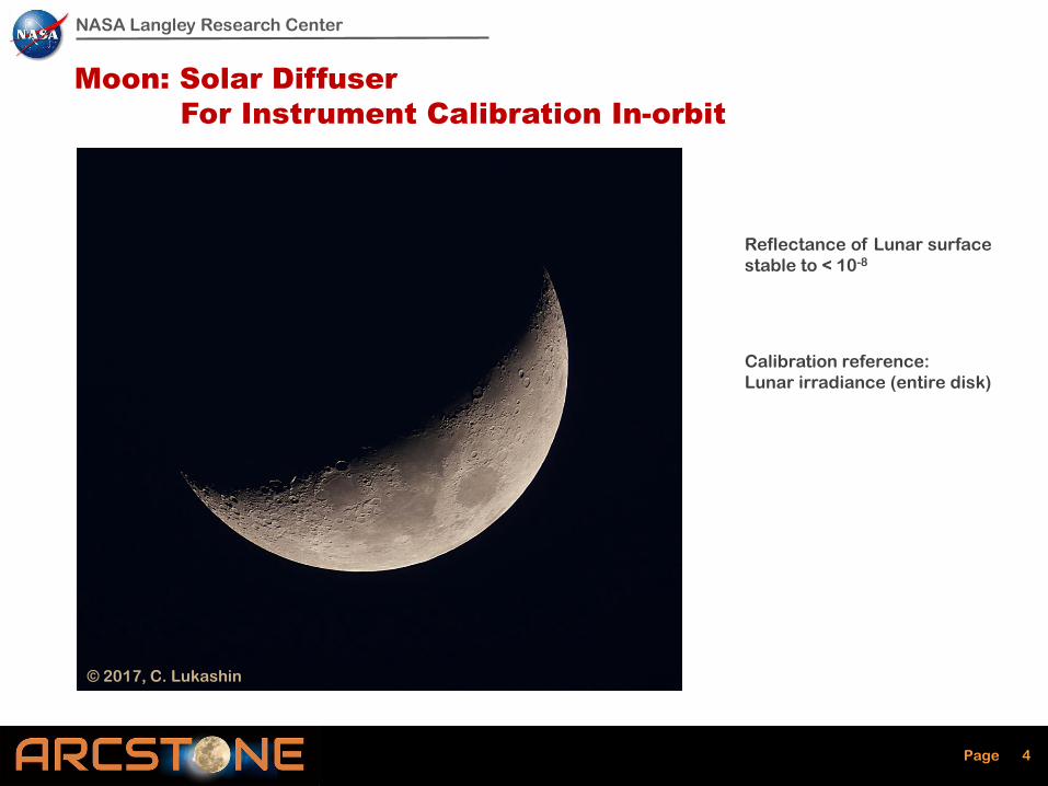
Moon: Solar Diffuser
For Instrument Calibration In-orbit
Reflectance of Lunar surface
stable to < 10-8
Calibration reference:
Lunar irradiance (entire disk)
NASA Langley Research Center
Page 5
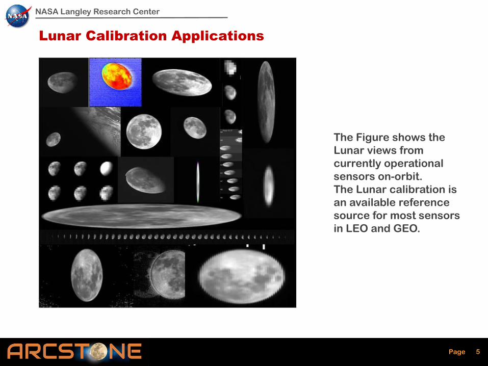
Lunar Calibration Applications
5
The Figure shows the
Lunar views from
currently operational
sensors on-orbit.
The Lunar calibration is
an available reference
source for most sensors
in LEO and GEO.
NASA Langley Research Center
Page 6
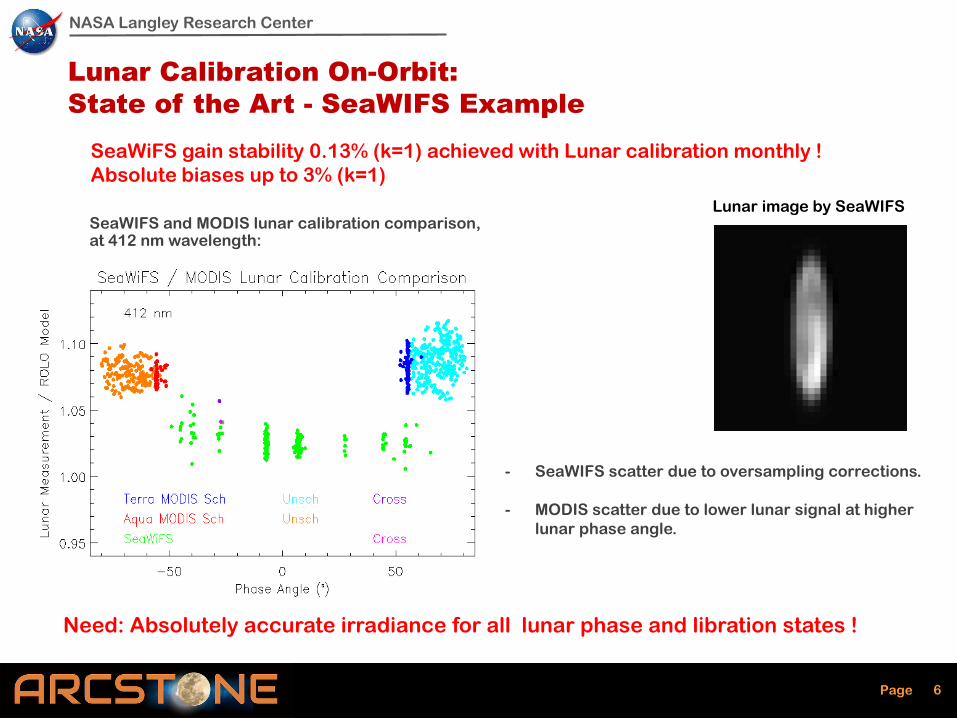
Lunar Calibration On-Orbit:
State of the Art - SeaWIFS Example
- SeaWIFS scatter due to oversampling corrections.
- MODIS scatter due to lower lunar signal at higher
lunar phase angle.
SeaWIFS and MODIS lunar calibration comparison, at 412 nm wavelength:
SeaWiFS gain stability 0.13% (k=1) achieved with Lunar calibration monthly !
Absolute biases up to 3% (k=1)
Need: Absolutely accurate irradiance for all lunar phase and libration states !
Lunar image by SeaWIFS
NASA Langley Research Center
Page 7
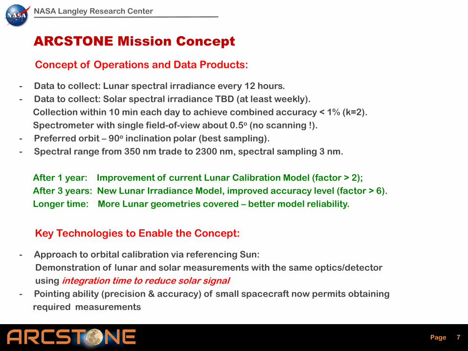
ARCSTONE Mission Concept
Concept of Operations and Data Products:
- Data to collect: Lunar spectral irradiance every 12 hours.
- Data to collect: Solar spectral irradiance TBD (at least weekly).
Collection within 10 min each day to achieve combined accuracy < 1% (k=2).
Spectrometer with single field-of-view about 0.5o (no scanning !).
- Preferred orbit – 90o inclination polar (best sampling).
- Spectral range from 350 nm trade to 2300 nm, spectral sampling 3 nm.
After 1 year: Improvement of current Lunar Calibration Model (factor > 2);
After 3 years: New Lunar Irradiance Model, improved accuracy level (factor > 6).
Longer time: More Lunar geometries covered – better model reliability.
Key Technologies to Enable the Concept:
- Approach to orbital calibration via referencing Sun:
Demonstration of lunar and solar measurements with the same optics/detector
using integration time to reduce solar signal
- Pointing ability (precision & accuracy) of small spacecraft now permits obtaining
required measurements

NASA Langley Research Center
Page 8
Key Performance
Parameters (KPP)
Threshold Value Goal Value
Accuracy (reflectance) 1.0% (k=1) 0.5% (k=1)
Stability < 0.15% (k=1) per decade < 0.1% (k=1) per decade
Orbit Sun-synch orbit Sun-synch orbit
Time on-Orbit 1 year 3 years
Frequency of sampling 24 hours 12 hours
Instrument pointing < 0.2o combined < 0.1o combined
Spectral Range 380 nm – 900 nm 350 nm – 2300 nm
Spectral Sampling 8 nm 4 nm
Reference for radiometric requirements (ROLO, T. Stone):
Lunar Phase Angle = 75o;
Irradiance = 0.6 (micro W / m2 nm)
Wavelength = 500 nm
ARCSTONE: Key Mission Performance Parameters
NASA Langley Research Center
Page 9
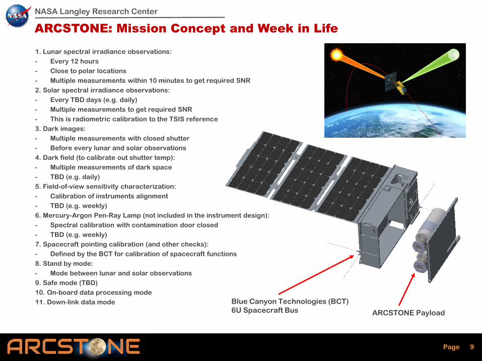
ARCSTONE: Mission Concept and Week in Life
1. Lunar spectral irradiance observations:
- Every 12 hours
- Close to polar locations
- Multiple measurements within 10 minutes to get required SNR
2. Solar spectral irradiance observations:
- Every TBD days (e.g. daily)
- Multiple measurements to get required SNR
- This is radiometric calibration to the TSIS reference
3. Dark images:
- Multiple measurements with closed shutter
- Before every lunar and solar observations
4. Dark field (to calibrate out shutter temp):
- Multiple measurements of dark space
- TBD (e.g. daily)
5. Field-of-view sensitivity characterization:
- Calibration of instruments alignment
- TBD (e.g. weekly)
6. Mercury-Argon Pen-Ray Lamp (not included in the instrument design):
- Spectral calibration with contamination door closed
- TBD (e.g. weekly)
7. Spacecraft pointing calibration (and other checks):
- Defined by the BCT for calibration of spacecraft functions
8. Stand by mode:
- Mode between lunar and solar observations
9. Safe mode (TBD)
10. On-board data processing mode
11. Down-link data mode
ARCSTONE Payload
Blue Canyon Technologies (BCT)
6U Spacecraft Bus

NASA Langley Research Center
Page 10
UV/Visible Channel*
(350 nm – 900 nm)
Short Wave IR Channel*
(880 nm – 2300 nm)
B1923 CCD Detector (Imperx)
Mini-Nyx 640
MCT Detector
(AIRS)
SF070 Cryocooler
(AIM)
ARCSTONE Design 6 Months Ago:
Instrument Overview
NASA Langley Research Center
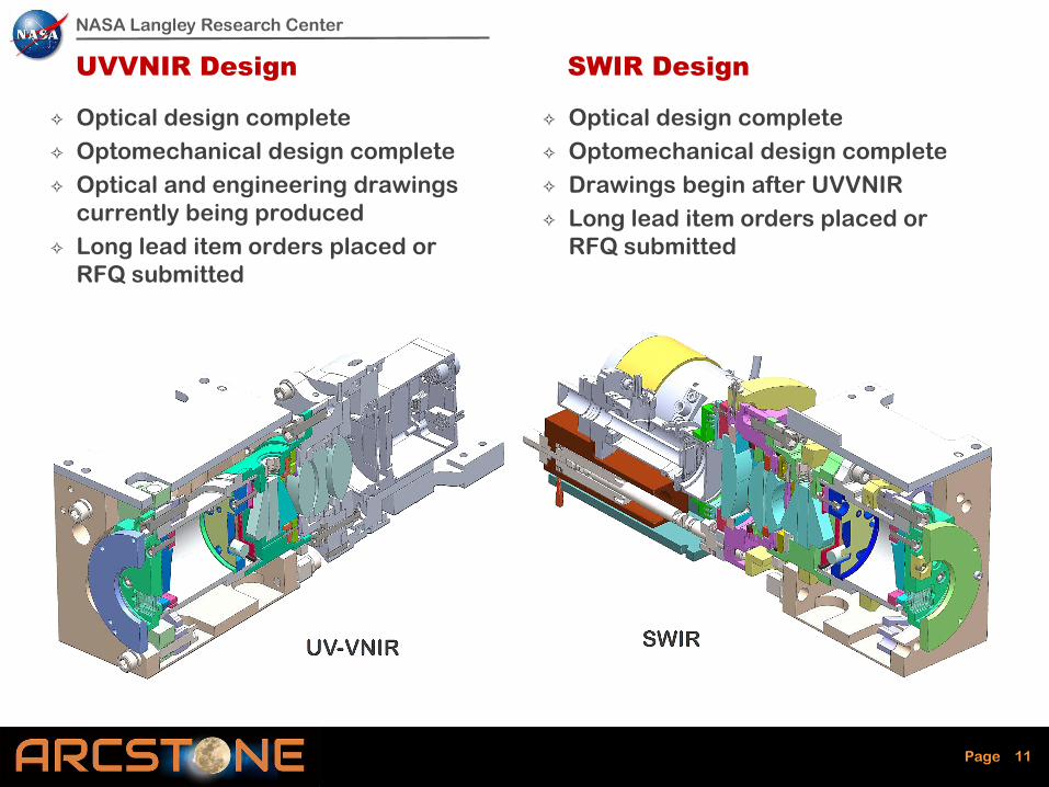
Page 11
UVVNIR Design
✧ Optical design complete
✧ Optomechanical design complete
✧ Optical and engineering drawings
currently being produced
✧ Long lead item orders placed or
RFQ submitted
✧ Optical design complete
✧ Optomechanical design complete
✧ Drawings begin after UVVNIR
✧ Long lead item orders placed or
RFQ submitted
SWIR Design
NASA Langley Research Center
Page 12
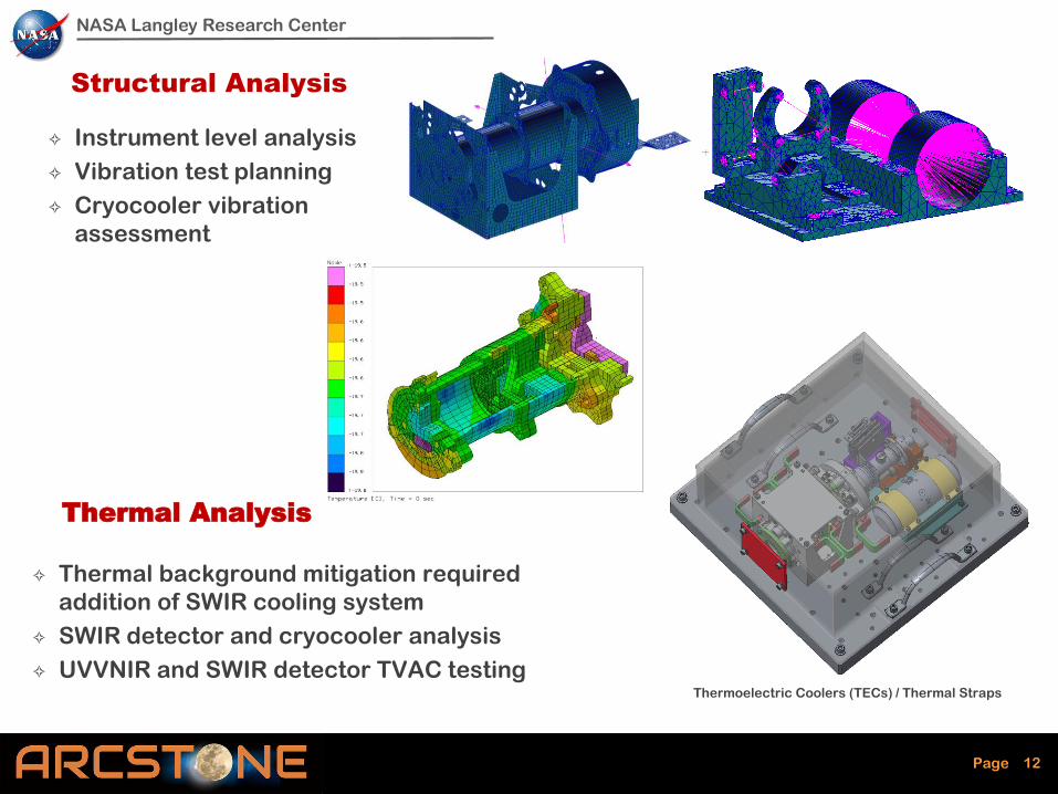
Structural Analysis
✧ Thermal background mitigation required
addition of SWIR cooling system
✧ SWIR detector and cryocooler analysis
✧ UVVNIR and SWIR detector TVAC testing
✧ Instrument level analysis
✧ Vibration test planning
✧ Cryocooler vibration
assessment
Thermal Analysis
Thermoelectric Coolers (TECs) / Thermal Straps
NASA Langley Research Center
Page 13
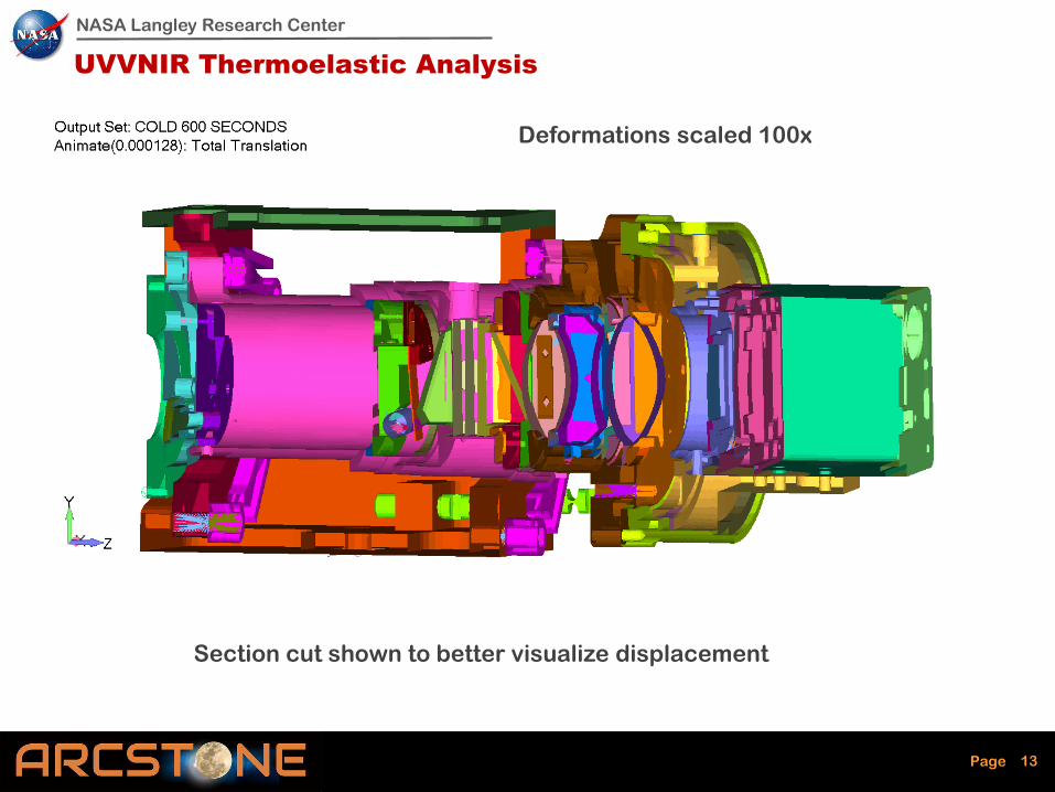
UVVNIR Thermoelastic Analysis
Section cut shown to better visualize displacement
Deformations scaled 100x
NASA Langley Research Center
Page 14
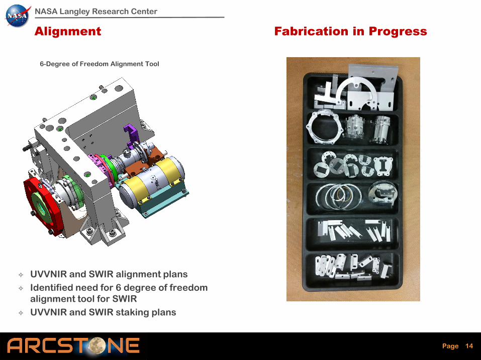
✧ UVVNIR and SWIR alignment plans
✧ Identified need for 6 degree of freedom
alignment tool for SWIR
✧ UVVNIR and SWIR staking plans
6-Degree of Freedom Alignment Tool
Alignment Fabrication in Progress
NASA Langley Research Center
Page 15
Software Development
✧ Flight-like and ground test
architecture design
✧ Blue Canyon Technologies (BCT)
spacecraft bus software simulator
✧ Instrument controller testing and
verification
Electronics Development
✧ UVVNIR and SWIR detector TVAC
testing
✧ UVVNIR and SWIR detector
calibration preparation
✧ Instrument controller configuration
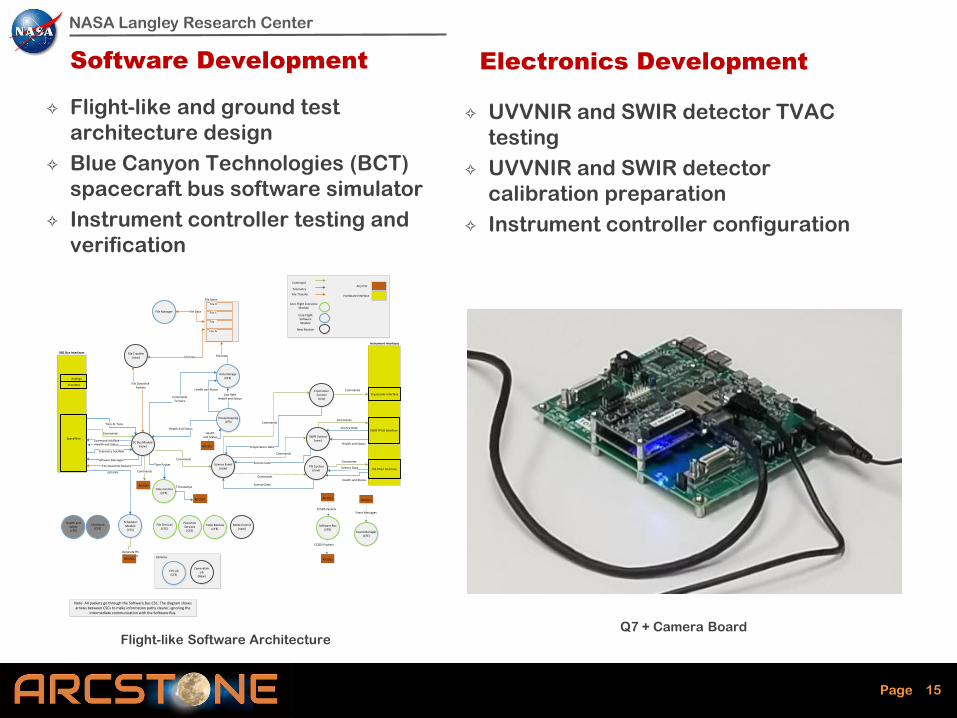
Q7 + Camera Board
VIS FPGA Interface
XB1 Bus Interfaces
Instrument Interfaces
SC Bus Module(new)
SWIR Control(new)
House Keeping(CFS)
Table Module(CFE)
Time Control(CFE)
Scheduler Module
(CFS)
Health and Status
Commands
Health and Status
Commands
Science DataSWIR FPGA Interface
Any CSC
Hardware Interface
Command
Telemetry
Core Flight ExecutiveModule
Core Flight Software Module
File Transfer
Analogs
Discretes
SpaceWire
New Module
File Services(CFE)
Software Bus(CFE)
Event Manager (CFE)
Executive Services
(CFE)
Data Storage(CFS)
Science Event (new)
VIS Control(new)
Health and Status
Commands
Science Data
Health and Status
Science Data
Science Data
CommandsTo Store
Time At Tone
Time Packet
Health and Status
All CSCs
Health and Status
Generate HS Commands
All CSCs
Commands
All CSCs
All CSCs
Timestamps
Low RateHealth and Status
File Data
File Store
File 0
File 1
File ..
File N
Checksum(CFS)
Health and Safety(CFS)
File Transfer(new) File Data
File Downlink Packets
Event Messages
All CSCsAll CSCs
All CSCs
CCSDS Packets
CCSDS Packets
GPS PPS
Commands
Commands
Commands
Mode Control(new)
CryoCooler Control(new)
Commands
Commands
CryoCooler Interface
File Downlink Packets
Software Messages
Note- All packets go through the Software Bus CSC. The diagram shows arrows between CSCs to make information paths clearer, ignoring the
intermediate communication with the Software Bus.
Command Ack/Nak
Telemetry Ack/Nak
File Manager File Data
Temperature Data
CFS Lib(CFS)
Cameralink Lib
(New)
Libraries
Flight-like Software Architecture

NASA Langley Research Center
Page 16
ARCSTONE UVVNIR Rendering (as fabricated)
NASA Langley Research Center
Page 17
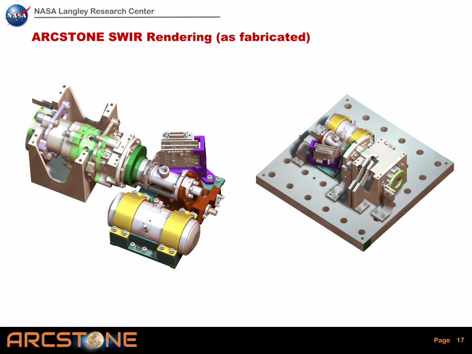
ARCSTONE SWIR Rendering (as fabricated)
NASA Langley Research Center
Page 18
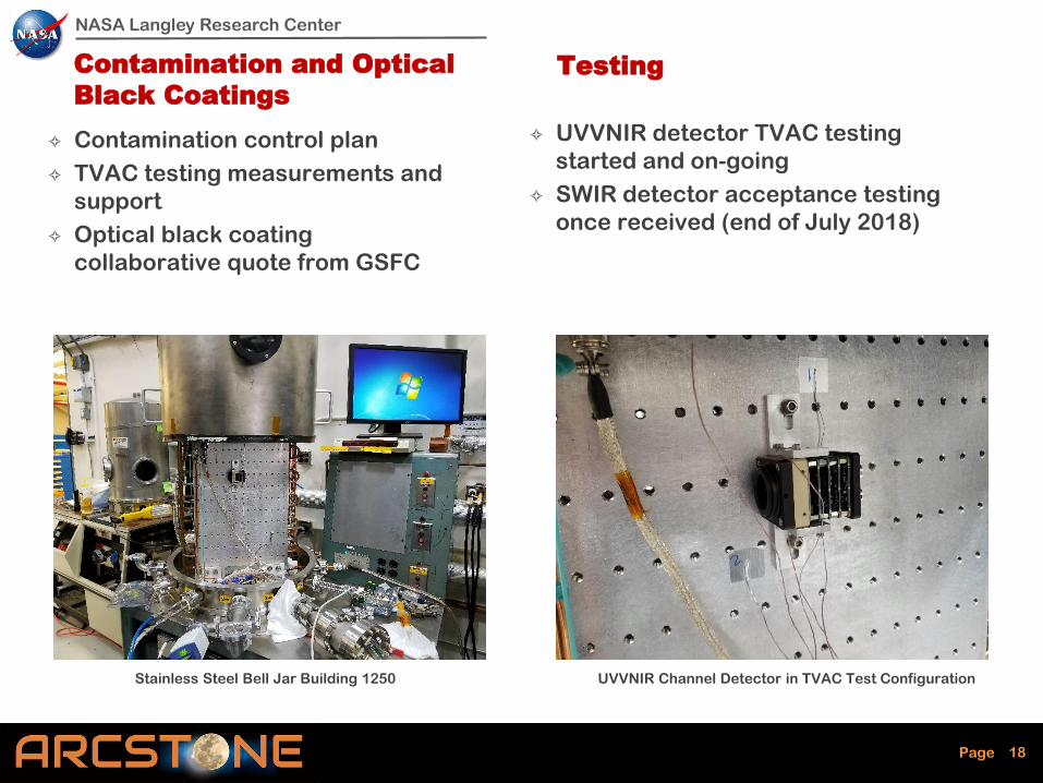
Contamination and Optical
Black Coatings
✧ Contamination control plan
✧ TVAC testing measurements and
support
✧ Optical black coating
collaborative quote from GSFC
Testing
✧ UVVNIR detector TVAC testing
started and on-going
✧ SWIR detector acceptance testing
once received (end of July 2018)
Stainless Steel Bell Jar Building 1250 UVVNIR Channel Detector in TVAC Test Configuration
NASA Langley Research Center
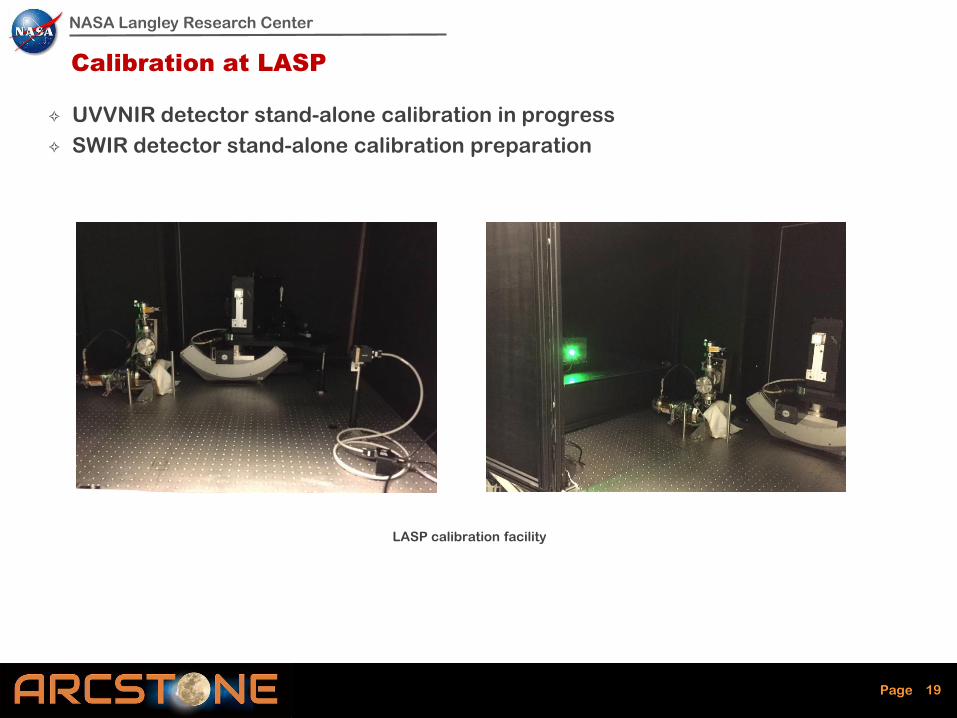
Page 19
Calibration at LASP
✧ UVVNIR detector stand-alone calibration in progress
✧ SWIR detector stand-alone calibration preparation
LASP calibration facility
NASA Langley Research Center
Page 20
ARCSTONE: Project Summary for June 2018
1. The formulation phase is completed successfully
2. Long-term procurement is completed
3. Instrument design 1st iteration by LaRC & Resonon completed
4. Instrument design 2nd iteration completed: Team and Quartus
5. STOP analysis completed: Quartus and Team
6. ARCSTONE started fabrication phase
7. ARCSTONE UVVNIR camera testing at LaRC and LASP
6. Schedule: coordinated for IIP and SBIR projects
7. Leveraging SBIR Phase-II (Resonon) and LaRC B&P funding
NASA Langley Research Center
Page 21
ARCSTONE IIP: Major Milestones
Major milestones (6 month intervals):
End of fiscal year (EOFY) 2017
MCT Detector/cryocooler assemblies and BCT bus simulator delivered
Initial instrument design (DAC 1 and DAC 2) and STOP analysis
completed
Middle of fiscal year (MOFY) 2018
Custom parts fabrication started, optic fabrication started, assembly
hardware/components ordered (build phase)
EOFY 2018
Instrument assembled and aligned at Resonon, Inc
MOFY 2019
Calibration and characterization at LASP
EOFY 2019
Environmental testing at LaRC
Documentation and closeout
21

NASA Langley Research Center
Page 22
ARCSTONE Web, http://arcstone.larc.nasa.gov
A new website… It will be developed further as the project goes forward

NASA Langley Research Center
Page 23
Thank you !
Questions ?