arcos modular femoral revision system - ormedic - … de cadera...2 arcos modular femoral revision...
TRANSCRIPT

Surgical Technique
Arcos™ Modular Femoral Revision System
Knees Hips ®

Contents
Pre-operative Planning and Approach ................................................................................... 1
Cone Proximal Body & STS™ Distal Stems
........................................................................................................ 4
Cone Proximal Body & STS™ Distal Stems
..................................................................................................... 10
Cone Proximal Body & PPS® Distal Stems
...................................................................................................... 16
Cone Proximal Body & PPS® Distal Stems
..................................................................................................... 24
Calcar/Broach Proximal Bodies & PPS® Distal Stems
..................................................................................................... 30
Calcar/Broach Proximal Bodies & STS™ Distal Stems
..................................................................................................... 36
ETO (Extended Trochanteric Osteotomy) Distal Stem
...................................................................................................... 44
Trochanteric Bolt and Claw Technique ................................................................................ 50
In-Femur Assembly .............................................................................................................. 54
Taper Compression Assembly ............................................................................................. 60
Disengaging the Taper Junction........................................................................................... 64
Ordering Information
........................................................................................................................... 66
...................................................................................................................... 74
................................................................................................................. 92
Arcos™ Modular Femoral Revision System

1
Pre-operative PlanningWhen planning a hip revision utilizing the Arcos™ Modular Femoral Revision System, carefully review the indications and contraindications for use referenced within the package insert located on pages 92–93 of this surgical technique.
The Arcos™ System is not designed for use in a fully unsupported proximal femur. Bone stock of adequate quality must be present and appraised at the time of surgery. The use of medial and/or lateral strut grafts may be necessary to support the taper junction in cases of severe proximal deficiency.
Utilizing A/P and M/L X-rays and implant templates will assist in determining the correct implant size, offset and position for a stable reconstruction (Figure 1). Final determination frequently cannot be made until the actual time of surgery, however with appropriate planning, a consistent operative plan with alternatives can be formulated.
Patient Positioning and Surgical ApproachThe goal of the surgical approach is to establish adequate visualization of the anatomy (Figure 2).
Figure 2Figure 1
The Arcos™ System was designed and developed in conjunction with Hugh Apthorp, FRCS, John Barrington, M.D., Keith R. Berend, M.D., J. Rod Davey, M.D., Edward McPherson, M.D., Christopher Peters, M.D., and Ian Stockley, FRCS.
™
-

2
Arcos™ Modular Femoral Revision System
Removal of a Cemented Component Once the stem has been removed from the cement mantle by utilizing universal extraction instruments or manufacturer specific instruments, ensure all cement is removed prior to preparation of the femur for the Arcos™ femoral components (Figure 3). This can be achieved using the Ultra-Drive® cement removal system or cement removal tools. An osteotomy of the femur may be necessary to facilitate removal of the cement.
Removal of a Cementless StemRemoval of a cementless stem may be difficult due to the biologic fixation that may exist between the implant and bone. When removing a proximally porous coated stem, it may be necessary to perform an osteotomy of the femur just below the level of the porous coating to assist in stem removal (Figure 4).
Note: An extended trochanteric osteotomy may be necessary if removing an extensively coated stem.
Figure 3 Figure 4

3
Figure 5
Sectioning the stem and utilizing trephine reamers can assist in the removal of the porous coated distal segment of a cementless stem (Figure 5).

Arcos™ Modular Femoral Revision System
4
™ Distal Stems Ream-Over Technique
Figure 1
Preparation of the Diaphysis To prepare the femur for an STS™ distal stem, select the STS™ reamers (silver reamers for 150 mm stem length and gold reamers for a 190 mm stem length). Assemble the STS™ reamer to the T-handle and turn the handle from torque limiting to the locked position (Figure 1).
Ream the femur in 1 mm increments by hand until the reamer advances to the 70 mm mark, referencing the tip of the greater trochanter.
Note: Reaming to the 70 mm etch mark on the STS™ reamer allows for a proximal height adjustment of 10 mm in either direction (e.g. 60 – 80 mm) depending on the final depth of the seated distal stem implant.
Note: The final depth of the implant may vary from the depth of the reamer. How aggressively the femur is prepared and the quality of the bone may impact the depth that the final implant will seat. If the final implant sits proud of the desired ream depth, note the difference between these and utilize the last reamer used to ream deeper into the femur. Reaming the femur by hand may help avoid any discrepancy between the reamed depth and the final depth of the implant.
Locked Position

5
Figure 2 Figure 3
Trialing the Distal Stem When distal reaming is complete, select the stem trial that is the same diameter as the final reamer and the necessary length for stem stability. Thread the distal stem trial inserter into the stem trial and insert the stem trial into the femur to the depth mark that matches the ream depth from the final reamer (Figure 2).
Note: The trial stem and reamer are the same size. Both are 1 mm smaller than the femoral implant.
Distal Stem Insertion Assemble the guide rod to the guide rod stem inserter by sliding the rod into the inserter, pulling back on the inserter collar and locking the rod into the stem inserter (Figure 3).
Inserter Collar
Guide Rod Stem Inserter
Guide Rod
Cone & STS
™ Stems
Ream
-Over Technique

Arcos™ Modular Femoral Revision System
6
™ Distal Stems Ream-Over Technique
Distal Stem Insertion (cont.)Thread the inserter assembly to the distal stem implant and seat the implant into the femur to the previously determined depth level, referencing the greater trochanter (Figure 4).
Note: If utilizing the 190 mm stem, ensure the bevel at the distal tip of the stem in oriented anteriorly.
Once the implant has been seated to the desired level, identify the depth on the inserter in reference to the greater trochanter to determine the height of the cone proximal body needed.
Note: The 50 mm, size A cone proximal body implant was not designed to accommodate a trochanteric bolt and claw. If a trochanteric bolt and claw is desired, utilize a cone proximal body implant with a 60, 70 or 80 mm vertical height.
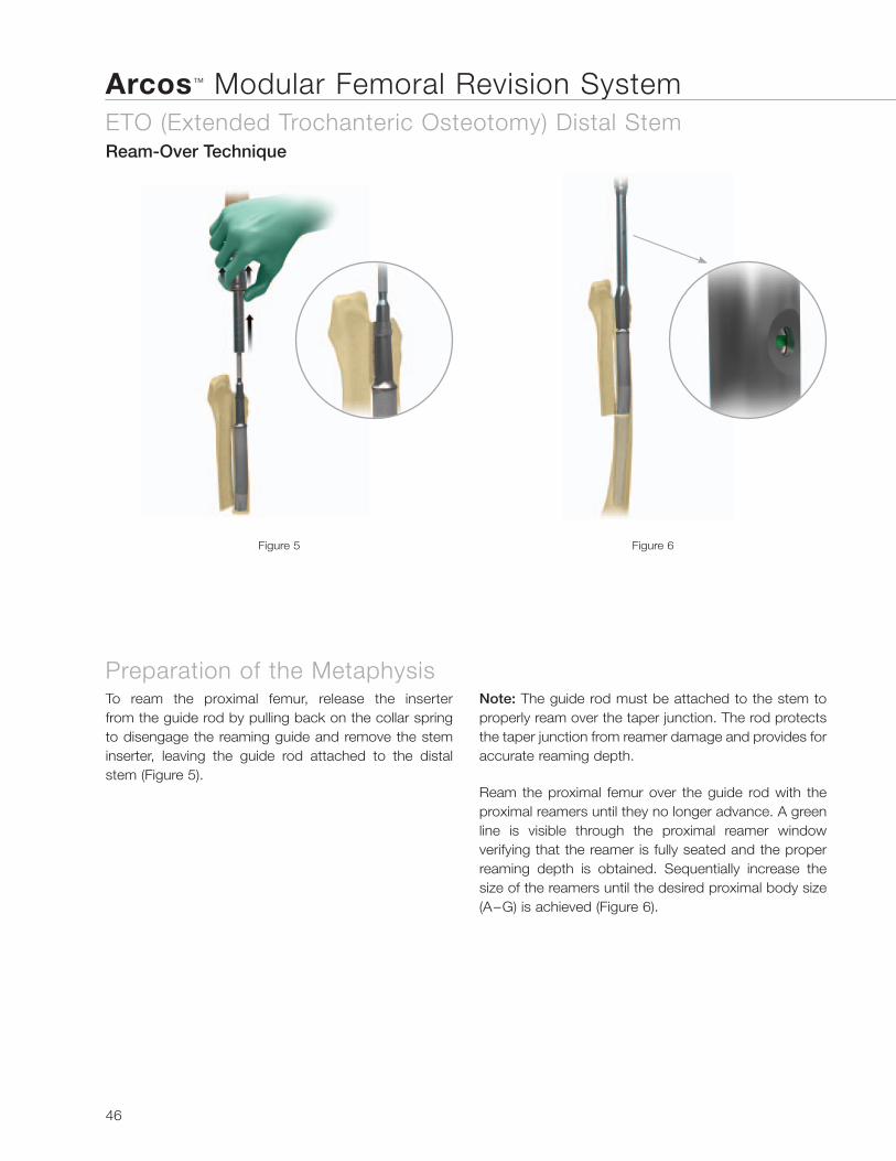
Preparation of the MetaphysisTo ream the proximal femur, release the inserter from the guide rod by pulling back on the collar spring to disengage the reaming guide and remove the stem inserter, leaving the guide rod attached to the distal stem (Figure 5).
Note: The guide rod must be attached to the stem to properly ream over the taper junction. The rod protects the taper junction from reamer damage and provides for accurate reaming depth.
Figure 5Figure 4

7
Figure 6 Figure 7 Figure 8
Ream the proximal femur over the guide rod with the proximal reamers until they no longer advance. A green line is visible through the proximal reamer window verifying that the reamer is fully seated and the proper reaming depth is obtained. Sequentially increase the size of the reamers until the desired proximal body size (A–G) is achieved (Figure 6).
Remove the guide rod from the distal stem implant with the guide rod removal tool, turning the removal tool counter-clockwise (Figure 7).
Trialing the Proximal Body To trial the proximal body, first ensure that the taper junction on the distal stem implant it is clean and dry. Attach the cone trial that is the same height and size as the final proximal reamer and the appropriate offset. The light green trial indicates standard offset, while the purple trial represents high offset.
Assemble the 3.5 mm hex driver to the T-handle and adjust the T-handle to the torque limiting position. Tighten the cone trial to the distal stem implant until the T-handle “clicks,” setting the desired anteversion or retroversion in the proximal body (Figure 8).
Note: The anti-rotation handle can be placed over the implant neck to control anteversion or retroversion.
Torque Limiting Position
Cone & STS
™ Stems
Ream
-Over Technique

Arcos™ Modular Femoral Revision System
8
™ Distal Stems Ream-Over Technique
Trial Reduction Utilizing modular head trials, perform a trial reduction and determine if the selected offset, leg length and joint stability are appropriate (Figure 9). In performing the trial range of motion, ensure the absence of impingement of the neck on the rim of the acetabular component or acetabular liner. Remove the cone proximal body trial from the femur with the 3.5 mm hex driver.
Proximal Body Insertion Note: Reference the Taper Compression Assembly section of this technique if an impaction assembly is not preferred.
Once the proper body height and size has been determined, thread the proximal body inserter to the proximal body implant, ensuring the anti-rotation tabs are locked in the proper orientation.
Impact the proximal body to the taper junction on the distal stem implant with several blows of the mallet (Figure 10). The implant will be seated when there is an audible change in the pitch during impaction or the etch mark of the inserter handle is advanced to the previously determined ream depth.
Figure 10Figure 9

9
Figure 11 Figure 12
Inserting the Locking Screw To lock the distal and proximal body implants, thread the locking screw into the top of the cone proximal body using the 3.5 mm hex driver and T-handle in the torque limiting position until a “click” is felt and heard (Figure 11).
Note: If the screw does not thread into the distal stem the proximal body is not fully seated and the implant insertion steps must be repeated.
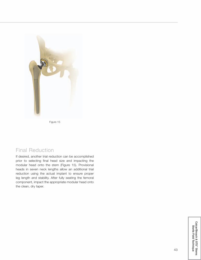
Final ReductionIf desired, another trial reduction can be accomplished prior to selecting final head size and impacting the modular head onto the stem (Figure 12). Provisional heads in seven neck lengths allow an additional trial reduction using the actual implant to ensure proper leg length and stability. After fully seating the femoral component, impact the appropriate modular head onto the clean, dry taper.
Torque Limiting Position
Cone & STS
™ Stems
Ream
-Over Technique

Arcos™ Modular Femoral Revision System
10
™ Distal Stems Sterile Field Technique
Preparation of the Diaphysis To prepare the femur for an STS™ distal stem, select the STS™ reamers (silver reamers for 150 mm stem length and gold reamers for a 190 mm stem length). Assemble the STS™ reamer to the T-handle and turn the handle from torque limiting to the locked position (Figure 1).
Ream the femur in 1 mm increments by hand until the reamer advances to the 70 mm mark, referencing the tip of the greater trochanter.
Figure 1
Note: Reaming to the 70 mm etch mark on the STS™ reamer allows for a proximal height adjustment of 10 mm in either direction (e.g. 60 – 80 mm) depending on the final depth of the seated distal stem implant.
Note: The final depth of the implant may vary from the depth of the reamer in this step. How aggressively the femur is prepared and the quality of the bone may impact the depth that the final implant will seat. If the final implant sits proud of the desired ream depth, note the difference between these and utilize the last reamer used to ream deeper into the femur. Reaming the femur by hand may help avoid any discrepancy between the reamed depth and the final depth of the implant.
Locked Position

11
Figure 2 Figure 3
Preparation of the MetaphysisTo prepare the proximal femur, assemble the final STS™ reamer into the proximal reamer and press down on the collar at the top of the proximal reamer to securely lock the two instruments together (Figure 2). Ream the proximal femur with the reamers, sequentially increasing the size of the proximal reamer, until the desired size (A–G) and proximal body height is achieved (Figure 3).
Proximal Reamer
STS™ Reamer
Cone & STS
™ Stems
Sterile Field Technique

Arcos™ Modular Femoral Revision System
12
™ Distal Stems Sterile Field Technique
TrialingSelect the proximal and distal stem trials that match the predetermined size, height and neck offset (standard or high). The light green trial indicates standard offset and the purple trial represents high offset. Assemble the proximal and distal stem trials together using the 3.5 mm hex driver and the T-handle in torque limiting position (Figure 4).
Thread the proximal body inserter into the proximal body trial. Insert the trial into the femur aligning the etched depth mark on the inserter with the tip of the greater trochanter (Figure 5).
Note: The anti-rotation handle can be placed over the trial neck to control anteversion or retroversion.
Figure 5Figure 4
Torque Limiting Position

13
Figure 6 Figure 7
Trial ReductionUtilizing modular head trials, perform a trial reduction and determine if the selected offset, leg length and joint stability are appropriate (Figure 6). In performing the trial range of motion, ensure the absence of impingement of the neck on the rim of the acetabular component or acetabular liner.
Once the desired offset, leg length and joint stability has been achieved, reattach the proximal inserter to the assembled trial and remove the trial from the femur. Unthread the proximal inserter form the assembled trial.
Implant AssemblyWith the trial still assembled in the sterile field, assemble the distal stem and proximal body to match the orientation of the assembled trial (Figure 7).
Cone & STS
™ Stems
Sterile Field Technique

Arcos™ Modular Femoral Revision System
14
™ Distal Stems Sterile Field Technique
Implant Assembly (cont.)When the desired position of the implants has been achieved, thread the proximal body inserter to the assembled implants and impact the taper junction with at least three blows of the mallet on the back table (Figure 8).
Note: When using a 190 mm stem, ensure the bevel at the distal tip of the stem is anterior.
Implant InsertionWith the proximal inserter still assembled to the implant, ensure the anti-rotation tabs are properly locked and insert the final implant into the femur until the desired depth is achieved (Figure 9).
Note: The final depth of the implant may vary from the depth of the reamer in this step. How aggressively the femur is prepared and the quality of the bone may impact the depth that the final implant will seat. If the final implant sits proud of the desired ream depth, note the difference between these and utilize the last reamer used to ream deeper into the femur. Reaming the femur by hand may help avoid any discrepancy between the reamed depth and the final depth of the implant.
Figure 8 Figure 9

15
Inserting the Locking ScrewTo lock the distal and proximal body implants, unthread the proximal body inserter from the implant and thread the locking screw into the top of the cone proximal body using the 3.5 mm hex and T-handle in the torque limiting position until a “click” is felt and heard (Figure 10).
Note: The screw can be used to lock the proximal body and distal stem together before the implants are inserted into the femur. If this is done, check the security of the screw once the implant has been fully seated.
Figure 11Figure 10
Final ReductionIf desired, another trial reduction can be accomplished prior to selecting final head size and impacting the modular head onto the stem (Figure 11). Provisional heads in seven neck lengths allow an additional trial reduction using the actual implant to ensure proper leg length and stability. After fully seating the femoral component, impact the appropriate modular head onto the clean, dry taper.
Torque Limiting Position
Cone & STS
™ Stems
Sterile Field Technique

Arcos™ Modular Femoral Revision System
16
® Distal Stems Ream-Over Technique
Preparation of the Diaphysis To prepare the femur for a PPS® distal stem, select flexible or thin shaft reamers and sequentially ream the femur two cortical diameters or 2-3 cm below the distal defect, increasing size until cortical “chatter” is achieved (Figure 1).
Note: When utilizing flexible reamers, ream the canal in 0.5 mm increments until cortical “chatter” is achieved. The final reamer diameter should be line to line or 0.5 mm larger than the diameter of the desired implant, depending on bone quality.
Note: Reaming over a guide is recommended. The Arcos™ distal reamers that are designed to prepare the femur for a bowed distal stem are cannulated to accommodate a guide wire.
Preparation of the Metaphysis: Part One To prepare the femur for the flared region of the PPS® distal stem, select the transition reamer that is the same size as the desired distal stem and ream to the depth of the desired proximal body height (60, 70 or 80 mm). The etch mark of the transition reamer, that corresponds to the proximal body height selected, should align with the tip of the greater trochanter.
Note: The 50 mm, size A cone proximal body implant was not designed to accommodate a trochanteric bolt and claw. If a trochanteric bolt and claw is desired, utilize a cone proximal body implant with a 60, 70 or 80 mm vertical height.
Figure 1 Figure 2

17
Trialing the Distal StemWhen distal reaming is complete, select the stem trial that is the same diameter as the final transition reamer and the necessary length for stem stability. Thread the distal trial stem inserter into the stem trial and insert the stem trial into the femur, matching the etched depth mark on the inserter to the depth achieved from the transition reamer (Figure 3).
Note: The stem trial will be 1.5 mm smaller than the final implant diameter as measured over the porous coating.
Figure 3
Cone & P
PS
® Stems
Ream
-Over Technique

Arcos™ Modular Femoral Revision System
18
® Distal Stems Ream-Over Technique
Distal Stem Insertion Assemble the guide rod to the guide rod stem inserter by sliding the rod into the inserter, pulling back on the inserter collar and locking the rod into the inserter (Figure 4). Thread this inserter assembly to the distal stem implant and seat the implant into the femur to the previously determined depth level, referencing the greater trochanter.
Figure 4 Figure 5
Once the implant has been seated to the desired level, identify the depth on the inserter in reference to the greater trochanter to determine the height of the cone proximal body needed (Figure 5).
Inserter Collar
Guide Rod Stem Inserter
Guide Rod

19
Figure 6 Figure 7 Figure 8
Preparation of the Metaphysis: Part TwoTo ream the proximal femur, release the inserter from the guide rod by pulling back on the collar spring to disengage the reaming guide and remove the stem inserter, leaving the guide rod attached to the distal stem (Figure 6).
Note: The guide rod must be attached to the stem to properly ream over the taper junction. The rod protects the taper junction from reamer damage and provides for accurate reaming depth.
Ream the proximal femur over the guide rod with the proximal reamers until they no longer advance. A green line is visible through the proximal reamer window verifying that the reamer is fully seated and the proper reaming depth is obtained. Sequentially increase the size of the reamers until the desired proximal body size (A–G) is achieved (Figure 7).
Remove the guide rod from the distal stem implant with the guide rod removal tool, turning the removal tool counter-clockwise (Figure 8).
Guide Rod
Guide Rod Removal Tool
Cone & P
PS
® Stems
Ream
-Over Technique

Arcos™ Modular Femoral Revision System
20
® Distal Stems Ream-Over Technique
Trialing the Proximal Body To trial the proximal body, first ensure that the taper junction on the distal stem implant is clean and dry. Attach the cone trial that is the same height and size as the final proximal reamer and the appropriate offset. The light green trial indicates standard offset and the purple trial represents high offset.
Assemble the 3.5 mm hex driver to the T-handle and adjust the T-handle to the torque limiting position. Tighten the cone trial to the distal stem implant until the T-handle “clicks,” setting the desired anteversion or retroversion in the proximal body (Figure 9).
Note: The anti-rotation handle can be placed over the neck of the trial to control anteversion or retroversion. Once the desired version has been achieved, use electrocautery to mark the desired position under the neck on the remaining bone stock.
Trial Reduction Utilizing modular head trials, perform a trial reduction and determine if the selected offset, leg length and joint stability are appropriate (Figure 10). In performing the trial range of motion, ensure the absence of impingement of the neck on the rim of the acetabular component or acetabular liner. Remove the cone trial from the femur with the 3.5 mm hex driver.
Figure 9 Figure 10
Torque Limiting Position

21
Figure 11
Proximal Body Insertion Note: Reference the Taper Compression Assembly section of this technique if an impaction assembly is not preferred.
Once the proper body height and size has been determined, thread the proximal body inserter to the proximal body implant, ensuring the anti-rotation tabs are locked in the proper orientation.
Impact the proximal body to the taper junction on the distal stem implant with several blows of the mallet (Figure 11). The implant will be seated when there is an audible change in the pitch during impaction or the etch mark of the inserter handle is advanced to the previously determined ream depth.
Cone & P
PS
® Stems
Ream
-Over Technique

Arcos™ Modular Femoral Revision System
22
® Distal Stems Ream-Over Technique
Inserting the Locking Screw To lock the distal and proximal body implants, thread the locking screw into the top of the cone proximal body using the 3.5 mm hex driver and T-handle in the torque limiting position until a “click” is felt and heard (Figure 12).
Note: If the screw does not thread into the distal stem the proximal body is not fully seated and the final implant assembly steps must be repeated.
Final ReductionIf desired, another trial reduction can be accomplished prior to selecting final head size and impacting the modular head onto the stem (Figure 13). Provisional heads in seven neck lengths allow an additional trial reduction, using the actual implant to ensure proper leg length and stability. After fully seating the femoral component, impact the appropriate modular head onto the clean, dry taper.
Figure 12 Figure 13
Torque Limiting Position

23
Cone & P
PS
® Stems
Ream
-Over Technique

Arcos™ Modular Femoral Revision System
24
® Distal Stems Sterile Field Technique
Preparation of the Diaphysis To prepare the femur for a PPS® distal stem, select flexible or thin shaft reamers and sequentially ream the femur two cortical diameters or 2–3 cm below the distal defect, increasing size until cortical “chatter” is achieved (Figure 1).
Note: When utilizing flexible reamers, advance the reamer into the canal in 0.5 mm increments until cortical “chatter” is achieved. The final reamer diameter should be line-to-line or 0.5 mm larger than the diameter of the desired implant, depending on bone quality.
Figure 1
Note: Reaming over a guide is recommended. The Arcos™ distal reamers that are designed to prepare the femur for a bowed distal stem are cannulated to accommodate a guide wire.

25
Figure 2 Figure 3
Preparation of the MetaphysisTo prepare the proximal femur for the tapered region of the PPS® distal stem and proximal body, assemble the transition reamer that is the same size as the desired distal stem into the proximal reamer and press down on the collar at the top of the proximal reamer to securely lock the two instruments together (Figure 2). Ream the proximal femur with the modular (transition/proximal) reamer, sequentially increasing the size of the proximal reamer, until the desired size (A–G) and proximal body height (60, 70 or 80 mm) is achieved. The etch mark of
the proximal reamer, that corresponds to the proximal body height selected, should align with the tip of the greater trochanter (Figure 3).
Note: The 50 mm, size A cone proximal body implant was not designed to accommodate a trochanteric bolt and claw. If a trochanteric bolt and claw is desired, utilize a cone proximal body implant with a 60, 70 or 80 mm vertical height.
Proximal Reamer
Transition Reamer
Cone & P
PS
® Stems
Sterile Field Technique

Arcos™ Modular Femoral Revision System
26
® Distal Stems Sterile Field Technique
TrialingSelect the proximal and distal stem trials that match the predetermined size, height and neck offset (standard or high). The light green trial indicates standard offset and the purple trial represents high offset. Loosely assemble the proximal and distal stem trials together using the 3.5 mm hex driver (Figure 4).
Note: Assemble the proximal and distal stem trials loose to allow the distal stem to find the appropriate position in the femur.
Thread the proximal body inserter into the proximal body trial. Insert the trial into the femur aligning the etched depth mark on the inserter with the tip of the greater trochanter (Figure 5).
Once the trial has been seated to the desired level, remove the proximal inserter, adjust the anteversion or retroversion on the proximal trial and lock the proximal body into place with the 3.5 mm hex driver (Figure 6).
Note: The anti-rotation handle can be placed over the neck of the trial to control anteversion or retroversion.
Figure 4 Figure 5 Figure 6

27
Figure 8Figure 7
Trial ReductionUtilizing modular head trials, perform a trial reduction and determine if the selected offset, leg length and joint stability are appropriate (Figure 7). In performing the trial range of motion, ensure the absence of impingement of the neck on the rim of the acetabular component or acetabular liner.
Once the desired offset, leg length and joint stability have been achieved remove the modular head trial. Reattach the proximal inserter to the assembled trial and remove the trial from the femur. Unthread the proximal inserter from the assembled trial.
Implant AssemblyWith the trial still assembled in the sterile field, assemble the distal stem and proximal body implants to match the orientation of the assembled trial (Figure 8).
Note: If utilizing a slotted stem, a straight osteotome can be used in the slot of the trial and implant to properly orient the distal stem in relation to the proximal body.
Cone & P
PS
® Stems
Sterile Field Technique

Arcos™ Modular Femoral Revision System
28
® Distal Stems Sterile Field Technique
Implant Assembly (cont.)When the desired orientation of the implants has been achieved, thread the proximal body inserter to the assembled implants and impact the taper junction with at least three blows of the mallet on the back table (Figure 9).
Implant InsertionWith the proximal inserter still assembled to the implant, ensure the anti-rotation tabs are properly locked and insert the final implant into the femur until the desired depth is achieved (Figure 10).
Figure 9 Figure 10

29
Figure 12Figure 11
Inserting the Locking ScrewTo lock the distal and proximal body implants, unthread the proximal body inserter from the implant and thread the locking screw into the top of the cone proximal body using the 3.5 mm hex drive and T-handle in torque limiting position until a “click” is felt and heard (Figure 11).
Note: The screw can be used to lock the proximal body and distal stem together before the implants are inserted into the femur. If this is done, check the security of the screw once the implant has been fully seated.
Final ReductionIf desired, another trial reduction can be accomplished prior to selecting final head size and impacting the modular head onto the stem (Figure 12). Provisional heads in seven neck lengths allow an additional trial reduction using the actual implant to ensure proper leg length and stability. After fully seating the femoral component, impact the appropriate modular head onto the clean, dry taper.
Torque Limiting Position
Cone & P
PS
® Stems
Sterile Field Technique

Arcos™ Modular Femoral Revision System® Distal Stems
Sterile Field Technique
30
Preparation of the Diaphysis To prepare the femur for a PPS® coated distal stem, select flexible or thin shaft reamers and sequentially ream the femur two cortical diameters or 2–3 cm below the distal defect, increasing size until cortical “chatter” is achieved (Figure 1).
Note: When utilizing flexible reamers, advance the reamer into the canal in 0.5 mm increments until cortical “chatter” is achieved. The final reamer diameter should be line-to-line or 0.5 mm larger than the diameter of the desired implant, depending on bone quality.
Note: Reaming over a guide is recommended. The Arcos™ distal reamers that are designed to prepare the femur for a bowed distal stem are cannulated to accommodate a guide wire.
Preparation of the Metaphysis To prepare the proximal femur for the tapered region of the PPS® distal stem and proximal body, assemble the transition reamer that is the same size as the desired distal stem into the proximal reamer and press down on the collar at the top of the proximal reamer to securely lock the two instruments together (Figure 2). Ream the proximal femur with the modular (transition/proximal) reamer, sequentially increasing the size of the proximal reamer, until the desired size (A–F) and the 60 mm proximal body height is achieved. The 60 mm etch mark of the proximal reamer should align with the tip of the greater trochanter (Figure 3).
Figure 1 Figure 2 Figure 3
Proximal Reamer
Transition Reamer

31
Figure 4
Broaching the Metaphysis Once the desired size and 60 mm proximal body height has been achieved utilizing the modular reamer, loosely assemble the proximal broach and the distal stem trial together using the 3.5 mm hex driver (Figure 4).
Note: Assemble the proximal broach and distal stem trial loose to allow the distal stem to find the appropriate position in the femur.
Broach the proximal femur sequentially, until the final broach size matches the last proximal reamer used (Figure 5). Verify that the broach is advanced into the femur, oriented to the desired anteversion, and the 60 mm etch mark on the broach handle is aligned with the tip of the greater trochanter.
Once the desired broach size is obtained, remove the broach handle and lock the broach into place with the 3.5 mm hex driver (Figure 6).
Note: Locking the broach and stem trial together will aid in matching the orientation of the trial to the final implant.
Figure 5 Figure 6
Calcar/B
roach & PP
S® Stem
s Sterile Field Technique

Arcos™ Modular Femoral Revision System® Distal Stems
Sterile Field Technique
32
Calcar Resection If utilizing the calcar proximal body implant, determine the level of deficiency in the proximal femur, align the resection guide to the broach and mark the desired resection with a saw (Figure 7). Remove the broach and stem trial with the broach handle and complete the calcar resection.
Insert either the large or small platform trial into the slot corresponding with the calcar resection level (Figure 8).
Note: The large platform should be utilized for a +0 resection level and the small platform should be utilized for the +10 or +20 resection levels.
Reattach the broach handle to the assembled trial and insert the trial into the femur to verify that it seats to the desired level.
Figure 7 Figure 8
+0
+10
+20

33
Figure 9 Figure 10
Trial ReductionUtilizing the modular neck and head trials, perform a trial reduction of the hip and determine if the selected offset, leg length and joint stability are appropriate (Figures 9 and 10). In performing the trial range of motion, ensure the absence of impingement of the neck on the rim of the acetabular component or acetabular liner.
Note: The gold modular trials indicate standard offset and the black trials indicate high offset.
Standard Offset
High Offset
Once the desired offset, leg length and joint stability have been achieved, remove the modular neck and head trials. Reattach the broach handle to the assembled trial and remove the trial from the femur. Detach the broach handle from the assembled trial.
Calcar/B
roach & PP
S® Stem
s Sterile Field Technique

Arcos™ Modular Femoral Revision System® Distal Stems
Sterile Field Technique
34
Implant Assembly With the trial still assembled in the sterile field, assemble the distal stem and proximal body implants to match the orientation of the assembled trial (Figure 11).
Note: If utilizing a slotted stem, a straight osteotome can be used in the slot of the trial and implant to properly orient the distal stem in relation to the proximal body.
When the desired orientation of the implants has been achieved, thread the proximal body inserter to the assembled implant and impact the taper junction with at least three blows of the mallet on the back table (Figure 12).
Figure 13
Implant Insertion With the proximal inserter still assembled to the implant, ensure the anti-rotation tabs are properly locked and insert the implant into the femur until the desired depth is achieved (Figure 13).
Figure 11 Figure 12

35
Figure 14 Figure 15
Inserting the Locking Screw To lock the distal and proximal body implants, thread the locking screw into the top of the proximal body using the 3.5 mm hex driver and the T-handle in torque limiting position until a “click” is felt and heard (Figure 14).
Note: The screw can be used to lock the proximal body and distal stem together before the implants are inserted into the femur. If this is done, check the security of the screw once the implant has been fully seated.
Final Reduction If desired, another trial reduction can be accomplished prior to selecting final head size and impacting the modular head onto the stem (Figure 15). Provisional heads in seven neck lengths allow an additional trial reduction using the actual implant to ensure proper leg length and stability. After fully seating the femoral component, impact the appropriate modular head onto the clean, dry taper.
Torque Limiting Position
Calcar/B
roach & PP
S® Stem
s Sterile Field Technique

Arcos™ Modular Femoral Revision System
36
™ Distal Stems Sterile Field Technique
Preparation of the Diaphysis™
™
™
Note:
Trialing the Distal Stem
™
Note:
Locked Position

37
Preparation of the Metaphysis™
Proximal Reamer
STS™ Reamer
Calcar/B
roach & STS™ Stem
s Sterile Field Technique

Arcos™ Modular Femoral Revision System
38
™ Distal Stems Sterile Field Technique
Broaching the
™
Note:

39
Calcar Resection If utilizing the calcar proximal body implant, determine the level of deficiency in the proximal femur, align the resection guide to the broach and mark the desired resection with a saw (Figure 7). Remove the broach and stem trial with the broach handle and complete the calcar resection.
Insert either the large or small platform trial into the slot corresponding with the calcar resection level (Figure 8).
Note: The large platform should be utilized for a +0 resection level and the small platform should be utilized for the +10 or +20 resection levels.
Reattach the broach handle to the assembled trial and insert the trial into the femur to verify that it seats to the desired level.
Figure 7 Figure 8
+0
+10
+20
Calcar/B
roach & STS™ Stem
s Sterile Field Technique

Arcos™ Modular Femoral Revision System
40
™ Distal Stems Sterile Field Technique
Trial ReductionUtilizing the modular neck and head trials, perform a trial reduction of the hip and determine if the selected offset, leg length and joint stability are appropriate (Figures 9 and 10). In performing the trial range of motion, ensure the absence of impingement of the neck on the rim of the acetabular component or acetabular liner.
Note: The gold modular trials indicate standard offset and the black trials indicate high offset.
Once the desired offset, leg length and joint stability have been achieved, remove the modular neck and head trials. Reattach the broach handle to the assembled trial and remove the trial from the femur. Detach the broach handle from the assembled trial.
Standard Offset
High Offset

41
Implant AssemblyWith the trial still assembled in the sterile field, assemble the distal stem and proximal body implants to match the orientation of the assembled trial (Figure 11).
Note: If utilizing the 190 mm stem, ensure the bevel at the distal tip of the stem is oriented anteriorly.
When the desired orientation of the implants has been achieved, thread the proximal body inserter to the assembled implant and impact the taper junction with at least three blows of the mallet on the back table (Figure 12).
Calcar/B
roach & STS™ Stem
s Sterile Field Technique

Arcos™ Modular Femoral Revision System
42
™ Distal Stems Sterile Field Technique
Implant InsertionWith the proximal inserter still assembled to the implant, ensure the anti-rotation tabs are properly locked and insert the final implant into the femur until the desired depth is achieved (Figure 13).
Note: The final depth of the implant may vary from the depth of the reamer in this step. How aggressively the femur is prepared and the quality of the bone may impact the depth that the final implant will seat. If the final implant sits proud of the desired ream depth, note the difference between these and utilize the last reamer used to ream deeper into the femur. Reaming the femur by hand may help avoid any discrepancy between the reamed depth and the final depth of the implant.
Inserting the Locking ScrewTo lock the distal and proximal body implants, thread the locking screw into the top of the proximal body using the 3.5 mm hex driver and the T-handle in torque limiting position until a “click” is felt and heard (Figure 14).
Note: The screw can be used to lock the proximal body and distal stem together before the implants are inserted into the femur. If this is done, check the security of the screw once the implant has been fully seated.
Torque Limiting Position
43
Final ReductionIf desired, another trial reduction can be accomplished prior to selecting final head size and impacting the modular head onto the stem (Figure 15). Provisional heads in seven neck lengths allow an additional trial reduction using the actual implant to ensure proper leg length and stability. After fully seating the femoral component, impact the appropriate modular head onto the clean, dry taper.
Calcar/B
roach & STS™ Stem
s Sterile Field Technique

Arcos™ Modular Femoral Revision System
Ream-Over Technique
44
Femoral OsteotomyWhen utilizing the ETO distal stem the only assembly option is the ream-over technique. Due to its unique design, this stem should only be used in cases when there is an osteotomy of the femur that allows for reaming of the most distal aspect of the femur (into and below the anatomic bow) (Figure 1).
Figure 1 Figure 2
Preparation of the DiaphysisTo prepare the femur for the ETO distal stem, select the STS™ reamers (silver reamers correspond to the 150 mm/250 mm ETO STS™ stem lengths). Assemble the STS™ reamer to the T-handle and turn the handle from torque limiting to the locked position.
Note: Reference the set of depth etch markings closest to the T-handle. The reamer flutes are also marked with additional depth etch marks to allow for a visual reference from the osteotomy level.
Ream the femur in 1 mm increments by hand until the reamer advances to the 70 mm mark, referencing the tip of the greater trochanter and measuring the reaming depth from the more proximal depth marks (Figure 2).
Note: Reaming to the 70 mm mark allows for a proximal height adjustment of 10 mm in either direction (e.g. 60 mm – 80 mm) depending on the final seated depth of the distal stem implant.
Locked Position

45
ETO D
istal Stem
Ream
-Over Technique
Figure 3 Figure 4
Note: The final depth of the implant may vary from the depth of the reamer in this step. How aggressively the femur is prepared and the quality of the bone may impact the depth that the final implant will seat. If the final implant sits proud of the desired ream depth, note the difference between these and utilize the last reamer used to ream deeper into the femur. Reaming the femur by hand may help avoid any discrepancy between the reamed depth and the final depth of the implant.
Distal Stem Insertion Once the final stem size has been determined, assemble the guide rod to the guide rod/stem inserter by sliding the rod into the inserter, pulling back on the inserter collar and locking the rod into the inserter (Figure 3).
Thread the inserter assembly to the distal stem implant and insert the implant into the femur such that the kink in the implant matches the anatomic bow of the femur and the distal stem is seated to the previously determined depth level, referencing the greater trochanter. Once the implant has been seated to the desired level, identify the depth on the inserter in reference to the greater trochanter to determine the height of the cone proximal body needed (Figure 4).
Note: The 50 mm, size A cone proximal body implant was not designed to accommodate a trochanteric bolt and claw. If a trochanteric bolt and claw is desired, utilize a cone proximal body implant with a 60, 70 or 80 mm vertical height.
The kink of the ETO stem should align with the anatomic bow of the femur
Inserter Collar
Guide Rod Stem Inserter
Guide Rod
Arcos™ Modular Femoral Revision System
Ream-Over Technique
46
Preparation of the MetaphysisTo ream the proximal femur, release the inserter from the guide rod by pulling back on the collar spring to disengage the reaming guide and remove the stem inserter, leaving the guide rod attached to the distal stem (Figure 5).
Note: The guide rod must be attached to the stem to properly ream over the taper junction. The rod protects the taper junction from reamer damage and provides for accurate reaming depth.
Ream the proximal femur over the guide rod with the proximal reamers until they no longer advance. A green line is visible through the proximal reamer window verifying that the reamer is fully seated and the proper reaming depth is obtained. Sequentially increase the size of the reamers until the desired proximal body size (A–G) is achieved (Figure 6).
Figure 5 Figure 6

47
ETO D
istal Stem
Ream
-Over Technique
Figure 7 Figure 8
Remove the guide rod from the distal stem implant with the guide rod removal tool, turning the removal tool counter-clockwise (Figure 7).
Trialing the Proximal Body To trial the proximal body, first ensure that the taper junction on the distal stem implant is clean and dry. Attach the cone trial that is the same height and diam-eter as the final proximal reamer and the appropriate offset. The light green trial indicates standard offset, while the purple trial represents high offset.
Assemble the 3.5 mm hex driver to the T-handle and adjust the T-handle to the torque limiting position. Tighten the proximal body trial to the distal stem implant until the T-handle “clicks,” setting the desired anteversion or retroversion in the proximal body (Figure 8).
Note: The anti-rotation handle can be placed over the trial neck to control anteversion or retroversion.
Guide Rod
Guide Rod Removal Tool
Torque Limiting Position

Arcos™ Modular Femoral Revision System
Ream-Over Technique
48
Trial Reduction Reduce the hip to ensure that proper leg length and joint stability have been achieved. In performing the trial range of motion, ensure the absence of impingement of the neck on the rim of the acetabular component or acetabular liner. Remove the cone proximal body trial from the femur with the 3.5 mm hex driver.
Proximal Body Insertion Note: Reference the Taper Compression Assembly Section of this technique if an impaction assembly is not preferred.
Once the proper body height and size has been determined, thread the proximal body inserter to the proximal body implant, ensuring the anti-rotation tabs are locked in the proper orientation.
Impact the proximal body to the taper junction on the distal stem implant with blows of the mallet (Figure 10). The implant will be seated when there is an audible change in the pitch during impaction or the etch mark of the inserter handle is advanced to the previously determined ream depth.
Figure 9 Figure 10

49
ETO D
istal Stem
Ream
-Over Technique
Inserting the Locking Screw To lock the distal and proximal body implants, thread the locking screw into the top of the proximal body using the 3.5 mm T-handle in the torque limiting position until a “click” is felt and heard (Figure 11).
Note: If the screw does not thread into the distal stem the proximal body is not fully seated and the implant insertion steps must be repeated.
Final ReductionIf desired, another trial reduction can be accomplished prior to selecting final head size and impacting the modular head onto the stem (Figure 12). Provisional heads in seven neck lengths allow an additional trial reduction using the actual implant to ensure proper leg length and stability. After fully seating the femoral component, impact the appropriate modular head onto the clean, dry taper.
Figure 11 Figure 12
Torque Limiting Position

Arcos™ Modular Femoral Revision System
50
Once the final implant has been reduced, the osteotomy can be repaired and stabilized by attaching a trochanteric claw directly to the implant.
Note: All proximal body designs accept a bolt and claw except the 50A Cone and 50A Calcar bodies.
Depending on the surgical approach and operative hip, select the appropriate trochanteric bolt guide instrument (Figure 1).
Figure 1 Figure 2
Use the 5.0 mm hex driver to thread the trochanteric bolt guide into the insertion hole on the proximal body, ensuring the anti-rotation tabs are locked to the proximal body implant. Place the trochanteric fragment between the implant and the trochanteric bolt guide (Figure 2).
Use the claw trials (large or small) to select the needed width.

51
Trochanteric Bolt
and Claw
Technique
Figure 3 Figure 4
Note: Both claws are 100 mm in length, measured from top to bottom (Figure 3).
Once the size has been determined, compress the claw implant to the bone fragment by threading the plunger tightly against the claw implant using the 5.0 mm hex driver and T-handle in the torque limiting position (Figure 4).
Note: Ensure that the head of the plunger is aligned with a hole in the claw to ensure that the bolt will pass through the claw into the implant.
Select the bolt length that corresponds with the depth marks on the outside of the trochanteric bolt guide as measured according to the position of the engraved line on the plunger. Choose the trochanteric bolt drill bit that matches the size of the proximal body implant (Size A–G) regardless of height or body style.
Example: If a size B cone body is used, select the size B trochanteric bolt drill bit. Selecting the correct size will prevent the drill from contacting the implant.
Note: Bolts are available in 1 mm increments.
100 mm
Narrow claw option
(16 mm)
Wide claw option (17.5 mm)
Both have grooves to accept cable attachments
Hex Driver
T-handle
Guide
Engraved Line

Arcos™ Modular Femoral Revision System
52
Advance the appropriate size drill bit through the plunger until the built-in stop bottoms out on the cylindrical surface of the outrigger (Figure 5).
Note: It is not possible to drill through the bolt hole on the claw trial, preparation must be performed with the final implant in place.
Compress the arms of the trochanteric bolt guide tightly to the claw and remove the measurement plunger with the 5.0 mm hex driver (Figure 6). Attach the 5.0 mm hex driver to the T-handle and set to torque limiting position.
Figure 5 Figure 6

53
Trochanteric Bolt
and Claw
Technique
Thread the bolt through the trochanteric bolt guide and into the proximal body until a “click” is felt and heard (Figure 7).
Note: It may be necessary to give the T-handle a few small taps with the mallet to ensure the bolt drops into the hole in the proximal body.
Figure 7 Figure 8 Figure 9
Once the bolt is secured to the implant, unthread the trochanteric bolt guide from the proximal body using the 5.0 mm hex driver (Figure 8).
Note: Cables may be added in the grooves of the claw for additional stability (Figure 9).
Note: If the trochanteric bolt guide is difficult to remove, unthread the trochanteric bolt by 1⁄2 of a turn, remove the guide and retighten the bolt with the T-handle in torque limiting position.

Arcos™ Modular Femoral Revision System
54
The in-femur assembly tool can be utilized with any proximal body and PPS® coated distal stem construct and was designed to allow for a bowed distal stem to seat in the proper anatomic orientation, independent of the proximal body implant.
Once the diaphysis and metaphysis has been prepared and trialed, the in-femur assembly tool can be utilized for the final insertion of the implant and to securely lock the taper junction.
Implant AssemblyThread the proximal fastener into the insertion hole on the proximal body implant (Figure 1). Slide the fastener into the proximal/distal inserter, pulling back on the inserter collar and locking the fastener into the inserter (Figure 2). Ensure that the anti-rotation tabs are locked to the implant.
Place the distal fastener that matches the selected proximal body height into the proximal/distal inserter handle. Depress the button at the top of the proximal/distal inserter handle and insert the assembly rod into the inserter (Figure 3).
Figure 1 Figure 2 Figure 3
Proximal Fastener
Distal Fastener
Proximal/Distal Inserter

55
In-Femur A
ssembly
Insert the 5.0 mm hex driver to the top of the proximal/distal inserter handle, hold the taper junction apart and thread the distal fastener into the distal stem (Figure 4).
Note: Do not engage the taper junction when threading the distal fastener rod into the distal stem.
Figure 4 Figure 5
Attach the proximal/distal inserter handle strike plate, tightening until a “click” is felt and heard. Impact the proximal body until it is 2–3 cm proud of the desired depth (Figure 5).
Note: When a “click” is heard while tightening the strike plate, the proximal body and distal stem are separated and cannot be locked during insertion into the femur.
2–3 cm

Arcos™ Modular Femoral Revision System
56
Proximal/Distal Inserter Handle
Anti-rotation Handle
Torque Wrench
Implant Assembly (cont.)To fully engage the taper junction, attach the torque wrench to the end of the proximal/distal inserter handle strike plate, place the anti-rotation handle over the implant neck and tighten until 300 in-lbs is indicated on the torque wrench shaft (Figure 6).
Figure 6 Figure 7
Disassemble the torque wrench and anti-rotation handle. Impact the stem to the desired depth (Figure 7).

57
In-Femur A
ssembly
Figure 9 Figure 10
Inserter Disassembly To loosen the strike plate, use the anti-rotation handle to hold the neck of the implant. Turn the torque wrench counter-clockwise and depress the button at the top of the proximal/distal inserter handle and unthread the strike plate (Figure 8).
Unthread the distal fastener from the distal stem implant using the 5.0 mm hex. Disengage the proximal/distal inserter by pulling back on the inserter collar (Figures 9 and 10).
Figure 8
Proximal/Distal Inserter Handle
Anti-rotation Handle
Torque Wrench

Arcos™ Modular Femoral Revision System
58
Inserter Disassembly (cont.) To remove the proximal fastener, utilize the taper assembly driver and unthread the proximal fastener from the proximal body implant (Figure 11).
Note: This inserter disassembly technique will NOT disassemble the implant.
Inserting the Locking Screw To lock the distal and proximal body implants, thread the locking screw into the top of the proximal body using the 3.5 mm hex driver and T-handle in torque limiting position until a “click” is felt and heard (Figure 12).
Note: If the screw does not thread into the distal stem the proximal body is not fully seated and the final implant assembly steps must be repeated.
Figure 11 Figure 12
Torque Limiting Position

59
In-Femur A
ssembly
Figure 13
Final ReductionIf desired, another trial reduction can be accomplished prior to selecting final head size and impacting the modular head onto the stem (Figure 13). Provisional heads in seven neck lengths allow an additional trial reduction using the actual implant to ensure proper leg length and stability. After fully seating the femoral component, impact the appropriate modular head onto the clean, dry taper.

Arcos™ Modular Femoral Revision System
60
Proximal Body Insertion Attaching the Proximal Body to the Distal Stem ImplantOnce the desired offset has been chosen, ensure that the taper junction on the distal stem implant is clean and dry. Attach the proximal fastener to the cone proximal body implant by threading the proximal fastener into the insertion hole on the cone proximal body implant (Figure 1). Place the proximal/distal inserter handle over the proximal fastener by pulling back on the inserter collar and locking the proximal body, ensuring the anti-rotation tabs are locked to the proximal body implant (Figure 2).
Place the distal fastener that matches the selected proximal body height into the proximal/distal inserter handle. Depress the button at the end of the proximal/distal inserter handle and insert the distal fastener into the inserter (Figure 3).
Figure 1 Figure 2 Figure 3
Proximal Fastener
Distal Fastener
Proximal/Distal Inserter

61
Insert the 5.0 mm hex driver into the top of the proximal/distal inserter handle and tightly thread the distal fastener into the distal stem (Figure 4). Attach the proximal/distal inserter handle strike plate, tightening until a “click” is felt and heard.
Set the desired version of the cone proximal body implant (Figure 5).
To fully engage the implant taper junction, attach the torque wrench to the end of the proximal/distal inserter handle strike plate, place the anti-rotation handle to the implant neck and tighten until 300 in-lbs is indicated on the torque wrench shaft (Figure 6).
Figure 4 Figure 5 Figure 6
Anti-rotation Handle
Torque Wrench
Taper Com
pression A
ssembly

Arcos™ Modular Femoral Revision System
62
Inserter DisassemblyTo remove the inserter from the fully seated implant, turn the torque wrench counter-clockwise while simultaneously depressing the button at the top of the proximal/distal inserter handle and unthread the strike plate (Figure 7). Unthread the distal fastener from the distal stem implant using the 5.0 mm hex driver (Figure 8).
Figure 7 Figure 8

63
Disengage the proximal/distal inserter by pulling back on the inserter collar (Figure 9). To remove the proximal fastener, utilize the taper assembly driver and unthread the proximal fastener from the proximal body implant (Figure 10).
Note: This inserter disassembly technique will NOT disassemble the implant.
Figure 9 Figure 10 Figure 11
Torque Limiting Position
Inserting the Locking Screw To lock the distal and proximal body implants, thread the locking screw into the top of the proximal body using the 3.5 mm hex driver and T-handle in torque limiting position until a “click” is felt and heard (Figure 11).
Note: If the screw does not thread into the distal stem the proximal body is not fully seated and the final implant assembly steps must be repeated.
Taper Com
pression A
ssembly

Arcos™ Modular Femoral Revision System
64
Disengaging the Proximal Body from the Distal Stem ImplantTo disengage the proximal body implant from the distal stem, remove the locking screw with the 3.5 mm hex driver and thread the taper disassembly tool that matches the proximal body height to the proximal body implant (Figure 1). Attach the torque wrench to the taper disassembly tool and with the anti-rotation
handle attached to the neck of the proximal body, turn the torque wrench clockwise until the proximal body disengages the distal stem (Figure 2). When resistance is felt, continue to slowly turn the torque handle and after each quarter turn of the handle, pull the underside of the taper disassembly tool until the proximal body disengages.
Figure 1 Figure 2

65
Disengaging the
Taper Junction

66
Arcos™ Modular Femoral Revision System
ProductStandard
Offset Part Number
High Offset Part Number
DescriptionVertical Body
HeightSize
11-30110111-30110211-30110311-30110411-30110511-301106
11-30111111-30111211-30111311-30111411-30111511-301116
Broached Proximal BodyBroached Proximal BodyBroached Proximal BodyBroached Proximal BodyBroached Proximal BodyBroached Proximal Body
60 mm60 mm60 mm60 mm60 mm60 mm
ABCDEF
ProductStandard
Offset Part Number
High Offset Part Number
DescriptionVertical Body
HeightSize
11-301200 11-301210 Calcar Proximal Body 50 mm A
11-30120111-30120211-30120311-30120411-30120511-301206
11-30121111-30121211-30121311-30121411-30121511-301216
+0 Calcar Proximal Body +0 Calcar Proximal Body +0 Calcar Proximal Body +0 Calcar Proximal Body +0 Calcar Proximal Body +0 Calcar Proximal Body
60 mm60 mm60 mm60 mm60 mm60 mm
ABCDEF
11-30122111-30122211-30122311-30122411-30122511-301226
11-30123111-30123211-30123311-30123411-30123511-301236
+10 Calcar Proximal Body+10 Calcar Proximal Body+10 Calcar Proximal Body+10 Calcar Proximal Body+10 Calcar Proximal Body+10 Calcar Proximal Body
60 mm60 mm60 mm60 mm60 mm60 mm
ABCDEF
11-30124111-30124211-30124311-30124411-30124511-301246
11-30125111-30125211-30125311-30125411-30125511-301256
+20 Calcar Proximal Body+20 Calcar Proximal Body+20 Calcar Proximal Body+20 Calcar Proximal Body+20 Calcar Proximal Body+20 Calcar Proximal Body
60 mm60 mm60 mm60 mm60 mm60 mm
ABCDEF

67
ProductStandard
Offset Part Number
High Offset Part Number
DescriptionVertical Body
HeightSize
11-301300 11-301310 Cone Proximal Body 50 mm A
11-30130111-30130211-30130311-30130411-30130511-30130611-301307
11-30131111-30131211-30131311-30131411-30131511-30131611-301317
Cone Proximal BodyCone Proximal BodyCone Proximal BodyCone Proximal BodyCone Proximal BodyCone Proximal BodyCone Proximal Body
60 mm60 mm60 mm60 mm60 mm60 mm60 mm
ABCDEFG
11-30132111-30132211-30132311-30132411-30132511-30132611-301327
11-30133111-30133211-30133311-30133411-30133511-30133611-301337
Cone Proximal BodyCone Proximal BodyCone Proximal BodyCone Proximal BodyCone Proximal BodyCone Proximal BodyCone Proximal Body
70 mm70 mm70 mm70 mm70 mm70 mm70 mm
ABCDEFG
11-30134111-30134211-30134311-30134411-30134511-30134611-301347
11-30135111-30135211-30135311-30135411-30135511-30135611-301357
Cone Proximal BodyCone Proximal BodyCone Proximal BodyCone Proximal BodyCone Proximal BodyCone Proximal BodyCone Proximal Body
80 mm80 mm80 mm80 mm80 mm80 mm80 mm
ABCDEFG
Ordering Inform
ation

68
Arcos™ Modular Femoral Revision System
Product Part Number Description Diameter Length
11-30051211-30051311-30051411-30051511-30051611-30051711-30051811-30051911-30052011-30052111-30052211-30052311-30052411-30052511-300526
Bowed Slotted Distal StemBowed Slotted Distal StemBowed Slotted Distal StemBowed Slotted Distal StemBowed Slotted Distal StemBowed Slotted Distal StemBowed Slotted Distal StemBowed Slotted Distal StemBowed Slotted Distal StemBowed Slotted Distal StemBowed Slotted Distal StemBowed Slotted Distal StemBowed Slotted Distal StemBowed Slotted Distal StemBowed Slotted Distal Stem
12 mm13 mm14 mm15 mm16 mm17 mm18 mm19 mm20 mm21 mm22 mm23 mm24 mm25 mm26 mm
150 mm150 mm150 mm150 mm150 mm150 mm150 mm150 mm150 mm150 mm150 mm150 mm150 mm150 mm150 mm
11-30061211-30061311-30061411-30061511-30061611-30061711-30061811-30061911-30062011-30062111-30062211-30062311-30062411-30062511-300626
Bowed Slotted Distal StemBowed Slotted Distal StemBowed Slotted Distal StemBowed Slotted Distal StemBowed Slotted Distal StemBowed Slotted Distal StemBowed Slotted Distal StemBowed Slotted Distal StemBowed Slotted Distal StemBowed Slotted Distal StemBowed Slotted Distal StemBowed Slotted Distal StemBowed Slotted Distal StemBowed Slotted Distal StemBowed Slotted Distal Stem
12 mm13 mm14 mm15 mm16 mm17 mm18 mm19 mm20 mm21 mm22 mm23 mm24 mm25 mm26 mm
200 mm200 mm200 mm200 mm200 mm200 mm200 mm200 mm200 mm200 mm200 mm200 mm200 mm200 mm200 mm
11-30071211-30071311-30071411-30071511-30071611-30071711-30071811-30071911-30072011-30072111-30072211-30072311-30072411-30072511-300726
Bowed Slotted Distal StemBowed Slotted Distal StemBowed Slotted Distal StemBowed Slotted Distal StemBowed Slotted Distal StemBowed Slotted Distal StemBowed Slotted Distal StemBowed Slotted Distal StemBowed Slotted Distal StemBowed Slotted Distal StemBowed Slotted Distal StemBowed Slotted Distal StemBowed Slotted Distal StemBowed Slotted Distal StemBowed Slotted Distal Stem
12 mm13 mm14 mm15 mm16 mm17 mm18 mm19 mm20 mm21 mm22 mm23 mm24 mm25 mm26 mm
250 mm250 mm250 mm250 mm250 mm250 mm250 mm250 mm250 mm250 mm250 mm250 mm250 mm250 mm250 mm

69
Product Part Number Description Diameter Length
11-30141211-30141311-30141411-30141511-30141611-30141711-30141811-30141911-30142011-30142111-301422
Straight Bullet-tip Distal StemStraight Bullet-tip Distal StemStraight Bullet-tip Distal StemStraight Bullet-tip Distal StemStraight Bullet-tip Distal StemStraight Bullet-tip Distal StemStraight Bullet-tip Distal StemStraight Bullet-tip Distal StemStraight Bullet-tip Distal StemStraight Bullet-tip Distal StemStraight Bullet-tip Distal Stem
12 mm13 mm14 mm15 mm16 mm17 mm18 mm19 mm20 mm21 mm22 mm
115 mm115 mm115 mm115 mm115 mm115 mm115 mm115 mm115 mm115 mm115 mm
11-30151211-30151311-30151411-30151511-30151611-30151711-30151811-30151911-30152011-30152111-30152211-30152311-30152411-30152511-301526
Bowed Bullet-tip Distal StemBowed Bullet-tip Distal StemBowed Bullet-tip Distal StemBowed Bullet-tip Distal StemBowed Bullet-tip Distal StemBowed Bullet-tip Distal StemBowed Bullet-tip Distal StemBowed Bullet-tip Distal StemBowed Bullet-tip Distal StemBowed Bullet-tip Distal StemBowed Bullet-tip Distal StemBowed Bullet-tip Distal StemBowed Bullet-tip Distal StemBowed Bullet-tip Distal StemBowed Bullet-tip Distal Stem
12 mm13 mm14 mm15 mm16 mm17 mm18 mm19 mm20 mm21 mm22 mm23 mm24 mm25 mm26 mm
150 mm150 mm150 mm150 mm150 mm150 mm150 mm150 mm150 mm150 mm150 mm150 mm150 mm150 mm150 mm
11-30161211-30161311-30161411-30161511-30161611-30161711-30161811-30161911-30162011-30162111-30162211-30162311-30162411-30162511-301626
Bowed Bullet-tip Distal StemBowed Bullet-tip Distal StemBowed Bullet-tip Distal StemBowed Bullet-tip Distal StemBowed Bullet-tip Distal StemBowed Bullet-tip Distal StemBowed Bullet-tip Distal StemBowed Bullet-tip Distal StemBowed Bullet-tip Distal StemBowed Bullet-tip Distal StemBowed Bullet-tip Distal StemBowed Bullet-tip Distal StemBowed Bullet-tip Distal StemBowed Bullet-tip Distal StemBowed Bullet-tip Distal Stem
12 mm13 mm14 mm15 mm16 mm17 mm18 mm19 mm20 mm21 mm22 mm23 mm24 mm25 mm26 mm
200 mm200 mm200 mm200 mm200 mm200 mm200 mm200 mm200 mm200 mm200 mm200 mm200 mm200 mm200 mm
11-30171211-30171311-30171411-30171511-30171611-30171711-30171811-30171911-30172011-30172111-30172211-30172311-30172411-30172511-301726
Bowed Bullet-tip Distal StemBowed Bullet-tip Distal StemBowed Bullet-tip Distal StemBowed Bullet-tip Distal StemBowed Bullet-tip Distal StemBowed Bullet-tip Distal StemBowed Bullet-tip Distal StemBowed Bullet-tip Distal StemBowed Bullet-tip Distal StemBowed Bullet-tip Distal StemBowed Bullet-tip Distal StemBowed Bullet-tip Distal StemBowed Bullet-tip Distal StemBowed Bullet-tip Distal StemBowed Bullet-tip Distal Stem
12 mm13 mm14 mm15 mm16 mm17 mm18 mm19 mm20 mm21 mm22 mm23 mm24 mm25 mm26 mm
250 mm250 mm250 mm250 mm250 mm250 mm250 mm250 mm250 mm250 mm250 mm250 mm250 mm250 mm250 mm
Ordering Inform
ation

70
Arcos™ Modular Femoral Revision System
Product Part Number Description Diameter Length
11-30081211-30081311-30081411-30081511-30081611-30081711-30081811-30081911-30082011-30082111-30082211-30082311-30082411-30082511-30082611-30082711-30082811-30082911-300830
STS™ Distal StemSTS™ Distal StemSTS™ Distal StemSTS™ Distal StemSTS™ Distal StemSTS™ Distal StemSTS™ Distal StemSTS™ Distal StemSTS™ Distal StemSTS™ Distal StemSTS™ Distal StemSTS™ Distal StemSTS™ Distal StemSTS™ Distal StemSTS™ Distal StemSTS™ Distal StemSTS™ Distal StemSTS™ Distal StemSTS™ Distal Stem
12 mm13 mm14 mm15 mm16 mm17 mm18 mm19 mm20 mm21 mm22 mm23 mm24 mm25 mm26 mm27 mm28 mm29 mm30 mm
150 mm150 mm150 mm150 mm150 mm150 mm150 mm150 mm150 mm150 mm150 mm150 mm150 mm150 mm150 mm150 mm150 mm150 mm150 mm
11-30091211-30091311-30091411-30091511-30091611-30091711-30091811-30091911-30092011-30092111-30092211-30092311-30092411-30092511-30092611-30092711-30092811-30092911-300930
STS™ Distal StemSTS™ Distal StemSTS™ Distal StemSTS™ Distal StemSTS™ Distal StemSTS™ Distal StemSTS™ Distal StemSTS™ Distal StemSTS™ Distal StemSTS™ Distal StemSTS™ Distal StemSTS™ Distal StemSTS™ Distal StemSTS™ Distal StemSTS™ Distal StemSTS™ Distal StemSTS™ Distal StemSTS™ Distal StemSTS™ Distal Stem
12 mm13 mm14 mm15 mm16 mm17 mm18 mm19 mm20 mm21 mm22 mm23 mm24 mm25 mm26 mm27 mm28 mm29 mm30 mm
190 mm190 mm190 mm190 mm190 mm190 mm190 mm190 mm190 mm190 mm190 mm190 mm190 mm190 mm190 mm190 mm190 mm190 mm190 mm
71
Product Part Number Description Diameter Length
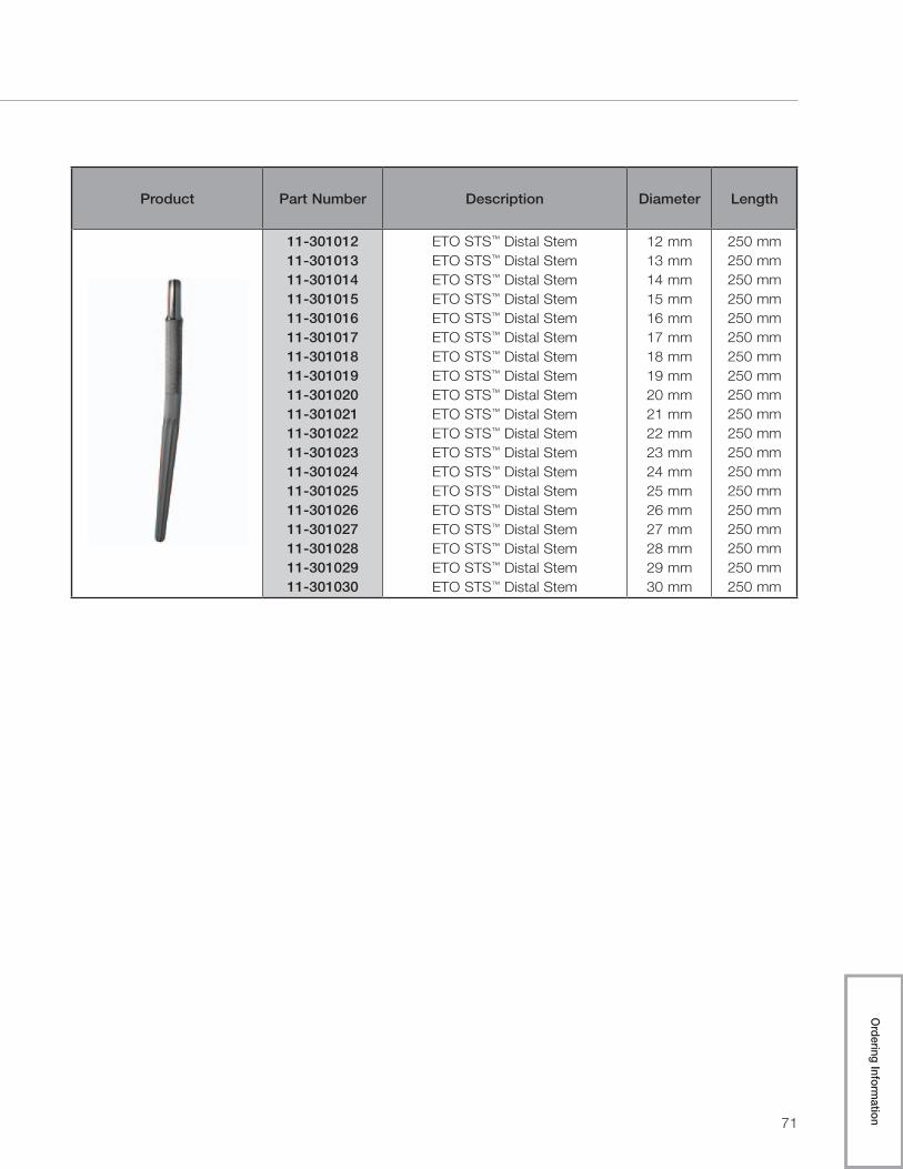
11-30101211-30101311-30101411-30101511-30101611-30101711-30101811-30101911-30102011-30102111-30102211-30102311-30102411-30102511-30102611-30102711-30102811-30102911-301030
ETO STS™ Distal StemETO STS™ Distal StemETO STS™ Distal StemETO STS™ Distal StemETO STS™ Distal StemETO STS™ Distal StemETO STS™ Distal StemETO STS™ Distal StemETO STS™ Distal StemETO STS™ Distal StemETO STS™ Distal StemETO STS™ Distal StemETO STS™ Distal StemETO STS™ Distal StemETO STS™ Distal StemETO STS™ Distal StemETO STS™ Distal StemETO STS™ Distal StemETO STS™ Distal Stem
12 mm13 mm14 mm15 mm16 mm17 mm18 mm19 mm20 mm21 mm22 mm23 mm24 mm25 mm26 mm27 mm28 mm29 mm30 mm
250 mm250 mm250 mm250 mm250 mm250 mm250 mm250 mm250 mm250 mm250 mm250 mm250 mm250 mm250 mm250 mm250 mm250 mm250 mm
Ordering Inform
ation

72
Arcos™ Modular Femoral Revision System
Product Part Number Description Size
11-301000 Proximal/Distal Screw –
11-30210111-302102
Trochanteric ClawTrochanteric Claw
LargeSmall

73
Product Part Number Description Size
11-30212411-30212511-30212611-30212711-30212811-30212911-30213011-30213111-30213211-30213311-30213411-30213511-30213611-30213711-30213811-30213911-30214011-30214111-30214211-30214311-30214411-30214511-30214611-30214711-30214811-30214911-30215011-30215111-30215211-30215311-302154
Trochanteric BoltTrochanteric BoltTrochanteric BoltTrochanteric BoltTrochanteric BoltTrochanteric BoltTrochanteric BoltTrochanteric BoltTrochanteric BoltTrochanteric BoltTrochanteric BoltTrochanteric BoltTrochanteric BoltTrochanteric BoltTrochanteric BoltTrochanteric BoltTrochanteric BoltTrochanteric BoltTrochanteric BoltTrochanteric BoltTrochanteric BoltTrochanteric BoltTrochanteric BoltTrochanteric BoltTrochanteric BoltTrochanteric BoltTrochanteric BoltTrochanteric BoltTrochanteric BoltTrochanteric BoltTrochanteric Bolt
24 mm25 mm26 mm27 mm28 mm29 mm30 mm31 mm32 mm33 mm34 mm35 mm36 mm37 mm38 mm39 mm40 mm41 mm42 mm43 mm44 mm45 mm46 mm47 mm48 mm49 mm50 mm51 mm52 mm53 mm54 mm
Ordering Inform
ation

74
Arcos™ Modular Femoral Revision System
593100 General Instrument Case—Top Tray
Product Label Part Number Description Size
A 31-301368 Distal Stem Reamer Guide –
B 31-302000 Distal Stem Trial Inserter –
C 31-301854 Guide Rod Stem Inserter –
D
31-30136131-30136231-30136331-30136431-301365
Proximal Reamer
ABCDE
E 31-301851Guide Rod Removal Tool & Taper Assembly Driver
–
F 31-301850 Torque Limiting T-Handle –
AB
C
D
E
F

75
593100 General Instrument Case—Bottom Tray
Product Label Part Number Description Size
A 31-301000 Proximal Body Inserter –
B 31-301870 Anti-Rotation Handle –
C 31-301114 Calcar Wrench –
D 31-301852 3.5 mm Hex Drive –
AA
BC
D
Ordering Inform
ation

76
Arcos™ Modular Femoral Revision System
593101 Assembly/Disassembly Instrument Case—Top Tray
Product Label Part Number Description Size
A
31-30200531-30200631-30200731-302008
Taper Assembly Tool-Distal Fastener
50 mm60 mm70 mm80 mm
A
77
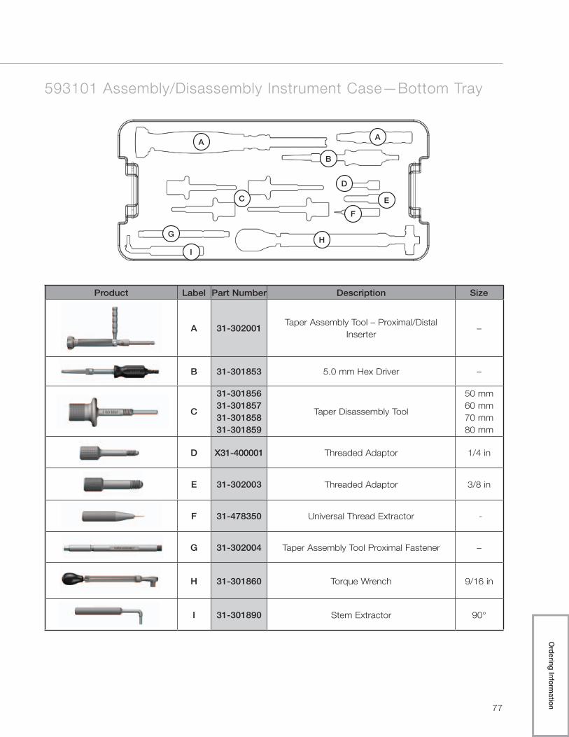
593101 Assembly/Disassembly Instrument Case—Bottom Tray
Product Label Part Number Description Size
A 31-302001Taper Assembly Tool – Proximal/Distal
Inserter–
B 31-301853 5.0 mm Hex Driver –
C
31-30185631-30185731-30185831-301859
Taper Disassembly Tool
50 mm60 mm70 mm80 mm
D X31-400001 Threaded Adaptor 1/4 in
E 31-302003 Threaded Adaptor 3/8 in
F 31-478350 Universal Thread Extractor -
G 31-302004 Taper Assembly Tool Proximal Fastener –
H 31-301860 Torque Wrench 9/16 in
I 31-301890 Stem Extractor 90°
AA
B
C
D
E
F
GH
I
Ordering Inform
ation

78
Arcos™ Modular Femoral Revision System
593102 Broach and Calcar Proximal Body Instrument Case
Product Label Part Number Description Size
A31-30111131-30111231-301113
Standard Offset TrunnionA
BCDEF
A31-30112131-30112231-301123
High Offset Trunnion A
BCDEF
B 31-30120050 mm Calcar Proximal Body Trial –
Standard OffsetA / 50 mm
C 31-30121050 mm Calcar Proximal Body Trial –
High OffsetA / 50 mm
D
31-30110131-30110231-30110331-30110431-301105
60 mm Proximal Body Broach
ABCDE
A B CD
EF
G
H

79
Product Label Part Number Description Size
E 31-301115 Broach Reference Resection Guide –
F 31-301107 Calcar Resection Guide –
G 31-555503 Broach Handle 60 mm
H31-30110931-301110
Calcar Shelf TrialLargeSmall
Ordering Inform
ation

80
Arcos™ Modular Femoral Revision System
593103 Cone Proximal Body Trials Instrument Case—Top Tray
Product Label Part Number Description Size
A 31-30120050 mm Calcar Proximal Body Trial -
Standard Offset A / 50 mm
A
31-30130050 mm Cone Proximal Body Trial -
Standard OffsetA / 50 mm
31-30130131-30130231-30130331-30130431-301305
60 mm Cone Proximal Body Trial - Standard Offset
A / 60 mmB / 60 mmC / 60 mmD / 60 mmE / 60 mm
31-30132131-30132231-30132331-30132431-301325
70 mm Cone Proximal Body Trial - Standard Offset
A / 70 mmB / 70 mmC / 70 mmD / 70 mmE / 70 mm
31-30134131-30134231-30134331-30134431-301345
80 mm Cone Proximal Body Trial - Standard Offset
A / 80 mmB / 80 mmC / 80 mmD / 80 mmE / 80 mm
A
B
81
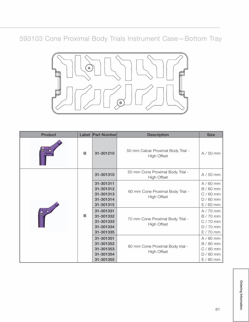
593103 Cone Proximal Body Trials Instrument Case—Bottom Tray
Product Label Part Number Description Size
B 31-30121050 mm Calcar Proximal Body Trial -
High OffsetA / 50 mm
B
31-30131050 mm Cone Proximal Body Trial -
High OffsetA / 50 mm
31-30131131-30131231-30131331-30131431-301315
60 mm Cone Proximal Body Trial - High Offset
A / 60 mmB / 60 mmC / 60 mmD / 60 mmE / 60 mm
31-30133131-30133231-30133331-30133431-301335
70 mm Cone Proximal Body Trial - High Offset
A / 70 mmB / 70 mmC / 70 mmD / 70 mmE / 70 mm
31-30135131-30135231-30135331-30135431-301355
80 mm Cone Proximal Body trial - High Offset
A / 80 mmB / 80 mmC / 80 mmD / 80 mmE / 80 mm
A
B
Ordering Inform
ation

82
Arcos™ Modular Femoral Revision System
593104 STS™ Distal Trials/Reamers 150/250 Instrument Case—Top Tray
A
Product Label Part Number Description Size
A
31-30086231-30086331-30086431-30086531-30086631-30086731-30086831-30086931-300870
STS™ Distal Reamer
12 mm x 150/250 mm13 mm x 150/250 mm14 mm x 150/250 mm15 mm x 150/250 mm16 mm x 150/250 mm17 mm x 150/250 mm18 mm x 150/250 mm19 mm x 150/250 mm20 mm x 150/250 mm

83
593104 STS™ Distal Trials/Reamers 150/250 Instrument Case—Bottom Tray
Product Label Part Number Description Size
B
31-30081231-30081331-30081431-30081531-30081631-30081731-30081831-30081931-300820
STS™ Distal Stem Trial
12 mm x 150 mm13 mm x 150 mm14 mm x 150 mm15 mm x 150 mm16 mm x 150 mm17 mm x 150 mm18 mm x 150 mm19 mm x 150 mm20 mm x 150 mm
B
Ordering Inform
ation

84
Arcos™ Modular Femoral Revision System
593105 STS™ Distal Trials/Reamers 190 Instrument Case—Top Tray
A
Product Label Part Number Description Size
A
31-30096231-30096331-30096431-30096531-30096631-30096731-30096831-30096931-300970
STS™ Distal Stem Reamers
12 mm x 190 mm13 mm x 190 mm14 mm x 190 mm15 mm x 190 mm16 mm x 190 mm17 mm x 190 mm18 mm x 190 mm19 mm x 190 mm20 mm x 190 mm

85
593105 STS™ Distal Trials/Reamers 190 Instrument Case—Bottom Tray
Product Label Part Number Description Size
B
31-30091231-30091331-30091431-30091531-30091631-30091731-30091831-30091931-300920
STS™ Distal Stem Trials
12 mm x 190 mm13 mm x 190 mm14 mm x 190 mm15 mm x 190 mm16 mm x 190 mm17 mm x 190 mm18 mm x 190 mm19 mm x 190 mm20 mm x 190 mm
B
Ordering Inform
ation

86
Arcos™ Modular Femoral Revision System
593106 Flexible Reamers Instrument Case—Top Tray
Product Label Part Number Description Size
A
31-30180531-30180631-30180731-30180831-30180931-30181031-30181131-30181231-30181331-301814
Flexible Shaft Reamers
9 mm9.5 mm10 mm
10.5 mm11 mm
11.5 mm12 mm
12.5 mm13 mm
13.5 mm
B
31-30181531-30181631-30181731-30181831-30181931-30182031-30182131-30182231-30182331-301824
Flexible Shaft Reamers
14 mm14.5 mm15 mm
15.5 mm16 mm
16.5 mm17 mm
17.5 mm18 mm
18.5 mm
C
31-30182531-30182631-30182731-30182831-30182931-30183031-301831
Flexible Shaft Reamers
19 mm19.5 mm20 mm
20.5 mm21 mm
21.5 mm22 mm
A

87
593106 Flexible Reamers Instrument Case—Middle Tray
593106 Flexible Reamers Instrument Case—Bottom Tray
C
B
Ordering Inform
ation

88
Arcos™ Modular Femoral Revision System
593108 Troch/Bolt Instrument Case
Product Label Part Number Description Size
A
31-30188131-30188231-30188331-30188431-301885
Troch Bolt Drill
ABCDE
B31-30100531-301006
Troch Bolt GuideRight P / Left ALeft P / Right A
C31-30210131-302102
Trial ClawLargeSmall
D 31-301853 5.0 mm Hex Driver –
A B
B
C
D

89
593109 Porous Distal Reamers Instrument Case
Product Label Part Number Description Size
A
31-30056231-30056331-30056431-30056531-30056631-30056731-30056831-30056931-300570
Distal Stem Transition Reamer
12 mm13 mm14 mm15 mm16 mm17 mm18 mm19 mm20 mm
A
Ordering Inform
ation

90
Arcos™ Modular Femoral Revision System
593110 Porous Distal Trials Instrument Case—Top Tray
Product Label Part Number Description Size
A
31-30141231-30141331-30141431-30141531-30141631-30141731-30141831-30141931-301420
115 mm Porous Distal Stem Trials
12 mm x 115 mm13 mm x 115 mm14 mm x 115 mm15 mm x 115 mm16 mm x 115 mm17 mm x 115 mm18 mm x 115 mm19 mm x 115 mm20 mm x 115 mm
B
31-30151231-30151331-30151431-30151531-30151631-30151731-30151831-30151931-301520
150 mm Porous Distal Stem Trial
12 mm x 150 mm13 mm x 150 mm14 mm x 150 mm15 mm x 150 mm16 mm x 150 mm17 mm x 150 mm18 mm x 150 mm19 mm x 150 mm20 mm x 150 mm
C
31-30161231-30161331-30161431-30161531-30161631-30161731-30161831-30161931-301620
200 mm Porous Distal Stem Trial
12 mm x 200 mm13 mm x 200 mm14 mm x 200 mm15 mm x 200 mm16 mm x 200 mm17 mm x 200 mm18 mm x 200 mm19 mm x 200 mm20 mm x 200 mm
D
31-30171231-30171331-30171431-30171531-30171631-30171731-30171831-30171931-301720
250 mm Porous Distal Stem Trial
12 mm x 250 mm13 mm x 250 mm14 mm x 250 mm15 mm x 250 mm16 mm x 250 mm17 mm x 250 mm18 mm x 250 mm19 mm x 250 mm20 mm x 250 mm
A

91
593110 Porous Distal Trials Instrument Case—Middle Top Tray
593110 Porous Distal Trials Instrument Case—Middle Bottom Tray
593110 Porous Distal Trials Instrument Case—Bottom Tray
B
C
D
Ordering Inform
ation

92
The information contained in this package insert was current on the date this brochure was printed. However, the package insert may have been revised after that date. To obtain a current package insert, please contact Biomet at the contact information provided herein.
Biomet Orthopedics 01-50-0997 56 East Bell Drive Date: 2010-09P.O. Box 587 Warsaw, Indiana 46581 USA
general surgical risks, possible adverse effects as listed, and to follow the instructions of the treating physician, including follow-up visits.
Patient selection factors to be considered include: 1) need to obtain pain relief and improve function, 2) ability and willingness of the patient to follow instructions, including control of weight and activity level, 3) a good nutritional state of the patient, and 4) the patient must have reached full skeletal maturity.
Patient smoking may result in delayed healing, non-healing and/or compromised stability in or around the placement site.
PRECAUTIONSSpecialized instruments are designed for Biomet® joint replacement systems to aid in the accurate implantation of the prosthetic components. The use of instruments or implant components from other systems can result in inaccurate fit, sizing, excessive wear and de-vice failure. Intraoperative fracture or breaking of instruments has been reported. Surgical instruments are subject to wear with normal usage. Instruments, which have experienced extensive use or excessive force, are susceptible to fracture. Surgical instruments should only be used for their intended purpose. Biomet recommends that all instruments be regu-larly inspected for wear and disfigurement.
Do not reuse implants. While an implant may appear undamaged, previous stress may have created imperfections that would reduce the service life of the implant. Do not treat patients with implants that have been, even momentarily, placed in a different patient.
POSSIBLE ADVERSE EFFECTS 1. Material sensitivity reactions. Implantation of foreign material in tissues can result in his-
tological reactions involving various sizes of macrophages and fibroblasts. The clinical significance of this effect is uncertain, as similar changes may occur as a precursor to or during the healing process. Particulate wear debris and discoloration from metallic and polyethylene components of joint implants may be present in adjacent tissue or fluid. It has been reported that wear debris may initiate a cellular response resulting in osteolysis or osteolysis may be a result of loosening of the implant. Further, there has been a report regarding an association between articulating surfaces of: 1) CoCrMo alloy on CoCrMo alloy, 2) CoCrMo alloy on polyethylene, and 3) Titanium alloy on polyethylene in hip replacements and increased genotoxicity. This report, however, did not assess either the clinical relevance of the data or make any definite conclusions as to which metal ions or interactions between metal ions or particulate metals might be responsible for the observed data. The report further cautioned that an association does not neces-sarily mean a causal relationship, and that any potentially increased risk associated with metal ions needs to be balanced against the benefits resulting from hip replacement.
2. Early or late postoperative infection and allergic reaction. 3. Intraoperative bone perforation or fracture may occur, particularly in the presence of
poor bone stock caused by osteoporosis, bone defects from previous surgery, bone resorption, or while inserting the device.
4. Loosening or migration of the implants can occur due to loss of fixation, trauma, ma-lalignment, malposition, bone resorption, or excessive unusual and/or awkward move-ment and/or activity.
5. Periarticular calcification or ossification, with or without impediment of joint mobility. 6. Inadequate range of motion due to improper selection or positioning of components. 7. Undesirable shortening of limb. 8. Dislocation and subluxation due to inadequate fixation, malalignment, malposition,
excessive, unusual and/or awkward movement and/or activity, trauma, weight gain, or obesity. Muscle and fibrous tissue laxity can also contribute to these conditions.
9. Fatigue fracture of component can occur as a result of loss of fixation, strenuous activity, malalignment, trauma, non-union, or excessive weight.
10. Fretting and crevice corrosion can occur at interfaces between components. 11. Fracture of the cross-screws. 12. Wear and/or deformation of articulating surfaces. 13. Trochanteric avulsion or non-union as a result of excess muscular tension, early weight
bearing, or inadequate reattachment. 14. Problems of the knee or ankle of the affected limb or contralateral limb aggravated by
leg length discrepancy, too much femoral medialization or muscle deficiencies. 15. Postoperative bone fracture and pain.
STERILITYProsthetic components are sterilized by exposure to a minimum dose of 25 kGy of gamma radiation. Do not resterilize. Do not use any component from an opened or damaged pack-age. Do not use implants after expiration date.
MRI InformationThe effects of the MR environment have not been determined for this device. This device has not been tested for heating or migration in the MR environment.
Caution: Federal law (USA) restricts this device to sale by or on the order of a physician.
Comments regarding this device can be directed to Attn: Regulatory Dept., Biomet, Inc., P.O. Box 587, Warsaw, IN 46581 USA, Fax 574-372- 3968.
All trademarks herein are the property of Biomet, Inc. or its subsidiaries unless otherwise indicated.
Authorized Representative: Biomet U.K., Ltd. Waterton Industrial Estate Bridgend, South Wales CF31 3XA, U.K.
0086
Biomet Orthopedics 56 East Bell Drive P.O. Box 587
Warsaw, Indiana 46581 USA
01-50-0997
Date: 2010-09
Biomet® Femoral Revision System
ATTENTION OPERATING SURGEON
DESCRIPTION Biomet’s Femoral Revision System is a comprehensive, press-fit revision
stem consisting of modular proximal and distal bodies with multiple
styles for reconstruction of various defects associated with femoral
revision surgery. Auxiliary implants to aid in fixation include trochanter
reattachment claws, bolts, and interlocking screws. The system is used
with Biomet® Type I Taper modular heads and compatible Biomet®
acetabular shells/liners and screws. Components are available in a variety
of designs and size ranges intended for uncemented primary and revision
procedures.
MATERIALS Proximal Bodies Titanium Alloy
Distal Stems Titanium Alloy
Claws and Bolts CoCrMo Alloy
Screws Titanium Alloy
Porous Coating Titanium Alloy
INDICATIONS 1. Noninflammatory degenerative joint disease including
osteoarthritis and avascular necrosis.
2. Rheumatoid arthritis.
3. Correction of functional deformity.
4. Treatment of non-union, femoral neck fracture, and trochanteric
fractures of the proximal femur with head involvement,
unmanageable using other techniques.
5. Revision of previously failed total hip arthroplasty.
The Biomet® Modular Femoral Revision System hip components are
single-use implants, intended for uncemented use only.
CONTRAINDICATIONS Absolute contraindications include: infection, sepsis, and osteomyelitis.
Relative contraindications include: 1) uncooperative patient or patient
with neurologic disorders who are incapable of following directions, 2)
osteoporosis, 3) metabolic disorders which may impair bone formation, 4)
osteomalacia, 5) distant foci of infections which may spread to the
implant site, 6) rapid joint destruction, marked bone loss or bone
resorption apparent on roentgenogram, and 7) vascular insufficiency,
muscular atrophy, or neuromuscular disease.
WARNINGS Improper selection, placement, positioning, alignment and fixation of the
implant components may result in unusual stress conditions which may
lead to subsequent reduction in the service life of the prosthetic
components. Malalignment of the components or inaccurate implantation
can lead to excessive wear and/or failure of the implant or procedure.
Inadequate preclosure cleaning (removal of surgical debris) can lead to
excessive wear. Improper preoperative or intraoperative implant handling
or damage (scratches, dents, etc.) can lead to crevice corrosion, fretting,
fatigue fracture and/or excessive wear. Use clean gloves when handling
implants. Do not modify implants. The surgeon is to be thoroughly
familiar with the implants and instruments, prior to performing surgery.
1. Use Biomet® femoral and modular head component with
appropriate matching “Type I Taper”.
2. Firmly seat modular components to prevent dissociation.
Thoroughly clean and dry taper prior to attachment of the modular
component to avoid crevice corrosion and improper seating.
3. Tight fixation of all non-cemented components at the time of
surgery is critical to the success of the procedure. Each
component must properly press fit into the host bone which
necessitates precise operative technique and the use of specified
instruments. Bone stock of adequate quality must be present and
appraised at the time of surgery.
4. Complete preclosure cleaning and removal of metallic debris and
other surgical debris at the implant site is critical to minimize
wear of the implant articular surfaces.
5. Distal cross-screws are intended to provide temporary
(<6 months) rotational stability only. Cross-screws are not
intended to carry any axial load.
Biomet® joint replacement prostheses provide the surgeon with a means
of reducing pain and restoring function for many patients. While these
devices are generally successful in attaining these goals, they cannot be
expected to withstand the activity levels and loads of normal, healthy
bone and joint tissue.
Accepted practices in postoperative care are important. Failure of the
patient to follow postoperative care instructions involving rehabilitation
can compromise the success of the procedure. The patient is to be
advised of the limitation of the reconstruction and the need for protection
of the implants from full load bearing until adequate fixation and healing
have occurred. Excessive, unusual and/or awkward movement and/or
activity, trauma, weight gain, and obesity have been implicated with
premature failure of the implant by loosening, fracture, dislocation,
subluxation and/or wear. It has been noted that this may be particularly
true where smaller sized stems are involved. Loosening of the implants
can result in increased production of wear particles, as well as accelerate
damage to bone, making successful revision surgery more difficult. The
patient is to be made aware and warned of general surgical risks, possible
adverse effects as listed, and to follow the instructions of the treating
physician, including follow-up visits.
Patient selection factors to be considered include: 1) need to obtain pain
relief and improve function, 2) ability and willingness of the patient to
follow instructions, including control of weight and activity level, 3) a
good nutritional state of the patient, and 4) the patient must have reached
full skeletal maturity.
Patient smoking may result in delayed healing, non-healing and/or
compromised stability in or around the placement site.
PRECAUTIONS Specialized instruments are designed for Biomet® joint replacement
systems to aid in the accurate implantation of the prosthetic components.
The use of instruments or implant components from other systems can
result in inaccurate fit, sizing, excessive wear and device failure.
Intraoperative fracture or breaking of instruments has been reported.
Surgical instruments are subject to wear with normal usage. Instruments,
which have experienced extensive use or excessive force, are susceptible
to fracture. Surgical instruments should only be used for their intended
purpose. Biomet recommends that all instruments be regularly inspected
for wear and disfigurement.
Do not reuse implants. While an implant may appear undamaged,
previous stress may have created imperfections that would reduce the
service life of the implant. Do not treat patients with implants that have
been, even momentarily, placed in a different patient.
POSSIBLE ADVERSE EFFECTS 1. Material sensitivity reactions. Implantation of foreign material in
tissues can result in histological reactions involving various sizes of
macrophages and fibroblasts. The clinical significance of this effect
is uncertain, as similar changes may occur as a precursor to or
during the healing process. Particulate wear debris and
discoloration from metallic and polyethylene components of joint
implants may be present in adjacent tissue or fluid. It has been
reported that wear debris may initiate a cellular response resulting in
osteolysis or osteolysis may be a result of loosening of the implant.
Further, there has been a report regarding an association between
articulating surfaces of: 1) CoCrMo alloy on CoCrMo alloy, 2)
CoCrMo alloy on polyethylene, and 3) Titanium alloy on
polyethylene in hip replacements and increased genotoxicity. This
report, however, did not assess either the clinical relevance of the
data or make any definite conclusions as to which metal ions or
Biomet® Femoral Revision System
ATTENTION OPERATING SURGEON
DESCRIPTIONBiomet’s Femoral Revision System is a comprehensive, press-fit revision stem consisting of modular proximal and distal bodies with multiple styles for reconstruction of various defects associated with femoral revision surgery. Auxiliary implants to aid in fixation include trochan-ter reattachment claws, bolts, and interlocking screws. The system is used with Biomet® Type I Taper modular heads and compatible Biomet® acetabular shells/liners and screws. Components are available in a variety of designs and size ranges intended for uncemented primary and revision procedures.
MaterialsProximal Bodies Titanium Alloy Distal Stems Titanium Alloy Claws and Bolts CoCrMo Alloy Screws Titanium Alloy Porous Coating Titanium Alloy
INDICATIONS 1. Noninflammatory degenerative joint disease including osteoarthritis and avascular ne-
crosis. 2. Rheumatoid arthritis. 3. Correction of functional deformity. 4. Treatment of non-union, femoral neck fracture, and trochanteric fractures of the proximal
femur with head involvement, unmanageable using other techniques. 5. Revision of previously failed total hip arthroplasty.
The Biomet® Modular Femoral Revision System hip components are single-use implants, intended for uncemented use only.
CONTRAINDICATIONSAbsolute contraindications include: infection, sepsis, and osteomyelitis.
Relative contraindications include: 1) uncooperative patient or patient with neurologic disor-ders who are incapable of following directions, 2) osteoporosis, 3) metabolic disorders which may impair bone formation, 4) osteomalacia, 5) distant foci of infections which may spread to the implant site, 6) rapid joint destruction, marked bone loss or bone resorption apparent on roentgenogram, and 7) vascular insufficiency, muscular atrophy, or neuromuscular disease.
WARNINGSImproper selection, placement, positioning, alignment and fixation of the implant compo-nents may result in unusual stress conditions which may lead to subsequent reduction in the service life of the prosthetic components. Malalignment of the components or inaccurate im-plantation can lead to excessive wear and/or failure of the implant or procedure. Inadequate preclosure cleaning (removal of surgical debris) can lead to excessive wear. Improper preoperative or intraoperative implant handling or damage (scratches, dents, etc.) can lead to crevice corrosion, fretting, fatigue fracture and/or excessive wear. Use clean gloves when handling implants. Do not modify implants. The surgeon is to be thoroughly familiar with the implants and instruments, prior to performing surgery.
1. Use Biomet® femoral and modular head component with appropriate matching “Type I Taper”.
2. Firmly seat modular components to prevent dissociation. Thoroughly clean and dry taper prior to attachment of the modular component to avoid crevice corrosion and improper seating.
3. Tight fixation of all non-cemented components at the time of surgery is critical to the success of the procedure. Each component must properly press fit into the host bone which necessitates precise operative technique and the use of specified instruments. Bone stock of adequate quality must be present and appraised at the time of surgery.
4. Complete preclosure cleaning and removal of metallic debris and other surgical debris at the implant site is critical to minimize wear of the implant articular surfaces.
5. Distal cross-screws are intended to provide temporary (<6 months) rotational stability only. Cross-screws are not intended to carry any axial
load. Biomet® joint replacement prostheses provide the surgeon with a means of reducing pain and restoring function for many patients. While these devices are generally successful in attaining these goals, they cannot be expected to withstand the activity levels and loads of normal, healthy bone and joint tissue.
Accepted practices in postoperative care are important. Failure of the patient to follow postoperative care instructions involving rehabilitation can compromise the success of the procedure. The patient is to be advised of the limitation of the reconstruction and the need for protection of the implants from full load bearing until adequate fixation and healing have occurred. Excessive, unusual and/or awkward movement and/or activity, trauma, weight gain, and obesity have been implicated with premature failure of the implant by loosening, fracture, dislocation, subluxation and/or wear. It has been noted that this may be particu-larly true where smaller sized stems are involved. Loosening of the implants can result in increased production of wear particles, as well as accelerate damage to bone, making successful revision surgery more difficult. The patient is to be made aware and warned of

The information contained in this package insert was current on the date this brochure was printed. However, the package insert may have been revised after that date. To obtain a current package insert, please contact Biomet at the contact information provided herein.
Manufacturer
Date of Manufacture
Do Not Reuse
Caution
Sterilized using Ethylene Oxide
Sterilized using Irradiation
Sterile
Sterilized using Aseptic Processing Techniques
Sterilized using Steam or Dry Heat
Use By
WEEE Device
Catalogue Number
Batch Code
Flammable
Authorized Representative in the European Community
