architecture framework for intelligent l ......electrical & computer engineering 678 spring 2004...
TRANSCRIPT
Electrical & Computer Engineering 678 Spring 2004
ILS3 Architecture Framework Page 1 of 190
AANN AARRCCHHIITTEECCTTUURREE FFRRAAMMEEWWOORRKK FFOORR
IINNTTEELLLLIIGGEENNTT LLAARRGGEE--SSCCAALLEE SSEENNSSIINNGG SSYYSSTTEEMMSS
DDEEVVEELLOOPPEEDD BBYY EELLEECCTTRRIICCAALL AANNDD CCOOMMPPUUTTEERR EENNGGIINNEEEERRIINNGG 667788 IINNTTEEGGRRAATTEEDD TTEELLEECCOOMMMMUUNNIICCAATTIIOONNSS SSYYSSTTEEMMSS
SSPPRRIINNGG 22000044 CCLLAASSSS PPRROOJJEECCTT IINN SSUUPPPPOORRTT OOFF TTHHEE IILLSS33 IINNIITTIIAATTIIVVEE
Program Manager
Kevin M. McNeill, PhD
Program Management Team George Zantis Mahesh Veena Saurabh Mittal
Integrated Project Team Leads
Alaa Muqattash Haiyan Qiao
Mingkuan Liu Samer Fayssal
Research Staff
Deepali Karadge Navneeth Kankani
Rajanikanth Jammalamadaka Rami Al-motlak
Robinson Cruso Marri Saju M. Alex Taekyu Kim
Traian Avram Vineet Agarwal
Yan Wang
Department of Electrical and Computer Engineering The University of Arizona, Tucson AZ 85721-0104
August 27, 2004
Electrical & Computer Engineering 678 Spring 2004
ILS3 Architecture Framework Page 2 of 190
Executive Summary The Intelligent Large Scale Sensing Systems (ILS3) initiative in the University of Arizona Department of Electrical and Computer Engineering is focused on the multi-disciplinary development of large sensing systems based on a network of heterogeneous sensors integrated with sensor fusion processing, based on the Joint Directors of Laboratories fusion model. The development of large scale sensing systems will be enhanced by the availability of an architectural framework. An architecture framework defines a common approach for Sensor-system architecture development, presentation and integration for building large scale sensor-network applications where information travels in a hierarchical manner. The framework is intended to ensure that architecture descriptions can be compared and related across different research and industrial groups. This document is an outcome of a class project (ECE 678 Integrated Telecommunications systems Spring 2004) in support of the ILS3 effort and has been developed by Graduate students, supervised by Professor Kevin M. McNeill. It describes a Sensing System Architectural Framework (SSAF) is modeled after the Department of Defense Architectural Framework (DoDAF) Ver. 1.0. The framework supports the development of interoperating and interacting architectures for sensor-networks. The SSAF provides a set of guiding principles and guidelines for building architectures for intelligent large scale sensing systems used in unrelated disciplines like hydrology, homeland security, etc. It also provides a workflow description of the high level processes that should be followed to document an SSAF compliant architecture. It also describes the data and the tools that must be used to facilitate and document the architecture development. Although SSAF is a subset of the DoDAF description, the guidelines for the products produced thereof follow the exact procedures and methodology as presented in DoDAF. The SSAF presents the Operational, System and Technical Views as described in DoDAF. This framework concludes by providing recommendations to multifarious aspects of a large-scale sensor network. It has covered both the communication-networking and the application-fusion aspects of these complex sensor-nets. The ILS3 architecture has proposed the existence of a ‘Sensor-Gateway’ that has an intermediate level of autonomy, in the constructed hierarchical sensor network. The Sensor-Gateway is a necessity that is required for channeling of information bottom-up and the commands in top-down fashion. It has been provided the capability to transform the RF protocol stack communication from sensors into the TCP/IP protocol stack, to be put-on the ubiquitous wireless IP network. It has also proposed the Sensor-fusion applications that are hierarchically laid out in the architectural framework, enabling the system to refine and aggregate information as it reaches the decision-maker. Recommendations for the RF-TCP/IP protocol stack, along with the applications that handle and refine sensor data have been provided as an outcome of this research effort. The ILS3 architectural framework encourages the designers to consider these recommendations in defining sensor network architecture.
Electrical & Computer Engineering 678 Spring 2004
ILS3 Architecture Framework Page 3 of 190
Table of Contents
Executive Summary ............................................................................................................. 2 Table of Contents................................................................................................................ 3 Table of Figures ................................................................................................................... 5 Background.......................................................................................................................... 8
Context and Problem Statement...................................................................................... 8 Statement of Objectives .................................................................................................. 9
Overview ........................................................................................................................... 17 Description of AF (from DoDAF) (Saurabh) .............................................................. 17 Approach....................................................................................................................... 18
Standards Based Approach ....................................................................................... 20 Decomposition (USSM)............................................................................................ 25
AF Products .................................................................................................................. 26 Operational View...................................................................................................... 26 Systems View............................................................................................................ 26 Technical View ......................................................................................................... 27 All View.................................................................................................................... 27
ILS3-AF Operational View Products .................................................................................. 28 Operational Concept Graphic (OCG) (Saurabh)........................................................... 28 Operational Node Network Architecture (ONNA)....................................................... 29 Operational Activity Model (OPACM) ........................................................................ 30
Networking Aspect (Assigned to Saurabh)............................................................... 32 Software-Fusion Aspect............................................................................................ 75 Sensor Platforms Aspect ........................................................................................... 93
Operational Activity Sequence and Timing Model (OSTM) ..................................... 101 Networking Aspect (assigned to Saurabh).............................................................. 101 Fusion Aspect (assigned to Mahesh) ...................................................................... 120 Sensor Platforms Aspect (Assigned to Mahesh)..................................................... 125
Logical Data Model (LDM)........................................................................................ 130 Logical Data Model (Fusion).................................................................................. 131 Logical Data Model (Platforms) ............................................................................. 136
Operational Information Exchange Matrix (OIEM) ................................................... 139 ILS3-AF Systems View Products ...................................................................................... 143
Systems Interface Description (George)..................................................................... 143 Systems Communications Description ....................................................................... 143 Systems Functionality Description ............................................................................. 143 Operational Activity to Systems Function Traceability Matrix.................................. 143 Systems Performance Parameters Matrix ................................................................... 143 Systems Technology Forecast..................................................................................... 143 Systems Rules Model.................................................................................................. 143 Systems State Transition Description ......................................................................... 143 Physical Schema ......................................................................................................... 143
Technical Views ............................................................................................................... 143 Technical Standards Profile (TV-1)............................................................................ 143 Technical Standards Forecast ..................................................................................... 143
Electrical & Computer Engineering 678 Spring 2004
ILS3 Architecture Framework Page 4 of 190
All View ........................................................................................................................... 143 Overview and Summary Information (KMM)............................................................ 143 Integrated Dictionary .................................................................................................. 143
Custom Protocols .................................................................................................... 143 Standard Protocols .................................................................................................. 143 Fusion Group .......................................................................................................... 143 Sensor Platforms ..................................................................................................... 143
Justification / satisfaction of requirements ....................................................................... 143 Conclusions ..................................................................................................................... 143 References........................................................................................................................ 143 Qualifications ................................................................................................................... 143 Management Team.......................................................................................................... 143
Managers..................................................................................................................... 143 IPT Leads: Networking Group.................................................................................... 143 Research Staff ............................................................................................................. 143
Custom Protocols Team.......................................................................................... 143 Standard Protocols Team ........................................................................................ 143 Platforms ................................................................................................................. 143 Fusion...................................................................................................................... 143
Electrical & Computer Engineering 678 Spring 2004
ILS3 Architecture Framework Page 5 of 190
Table of Figures
Figure 1.0: Unified Sensing System Model...................................................................... 10 Figure 1.1: Linkages among Views .................................................................................. 17 Figure 1.2: The development process for ILS3 Framework for DoDAF ......................... 18 Figure 1.3: System and Technical View development Process (Yellow boxes are created
in the previous flow char) ......................................................................................... 19 Figure 1.4: Unified Sensor Systems.................................................................................. 25 Figure 2.1: Operational Concept Graphic......................................................................... 28 Figure 2.2: Notional Network Architecture ...................................................................... 29 Figure 2.5.1: Hierarchical Organization of activities for RF communication
(OPACM_nrf1) ......................................................................................................... 33 Figure2.5.4: OPACM for Transport Layer Management (OPACM_nrf2)....................... 36 Figure 2.5.7: OPACM_nrf1.2 ........................................................................................... 39 Figure 2.5.8: OPACM for MAC Layer Management (OPACM_nrf1.3) ......................... 40 Figure 2.5.9: Periodic Active and Sleep ........................................................................... 41 Figure 2.5.10: Contention mechanism.............................................................................. 43 Figure 2.6: OPACM for wired and wireless IP communication. OPACM_nip1 ............. 45 Figure 2.6.1:Telnet control functions................................................................................ 46 Figure 2.6.2: Operational Activity for Telnet (OPACM_nip2) ........................................ 47 Figure 2.6.3: FTP Control Functions ................................................................................ 48 Figure 2.6.4: Operational Activity for RTSP (OPACM_nip3)......................................... 50 Fig 2.6.5. Operational Activity Model for SNMP (OPACM_nip4) ................................. 52 Fig 2.6.6. Operational Activity model for HTTP (OPACM_nip4)................................... 55 Figure 2.6.7: Operational Activities of TCP (OPACM_nip5).......................................... 57 Figure 2.6.10: Operational Activity of UDP (OPACM_nip6).......................................... 60 Figure 2.6.11: UDP encapsulation. ................................................................................... 61 Figure 2.6.13: Fields used for computation of UDP checksum........................................ 62 Figure 2.6.14: Operational Activities of DHCP (OPACM_nip7)..................................... 64 Figure 2.6.15: Operational Activities associated with DNS (OPACM_nip8) .................. 66 Figure 2.6.16: Operational Activities associated with ICMP (OPACM_nip10) .............. 68 Figure 2.6.17: Operational activity model for 802.11 b/g MAC Layer (OPACM_nip11)72 Figure 2.6.18: Operational activities associated with 802.11 b.g MAC Layer
(OPACM_nip12)....................................................................................................... 74 Figure 2.7: The components in the Multisensor data fusion system................................ 76 Fig 2.7.1: Operational activity for the fusion group (OPACM_fs)................................... 79 Figure 2.7.2: Operational Activity diagram for data fusion (OPACM_fsfp) ................... 82 Figure 2.7.3: Location-centric approach for target tracking ............................................. 85 Figure: 2.7.4: Flowchart of the processing performed at any given node to allow
distributed target tracking. ........................................................................................ 86 Figure 2.7.5: Operational Activity for a node in a tracking cell (OPACM_fst1) ............. 87 Figure 2.7.6: Operational Activity for the manager node in a tracking cell (OPACM_fst2)
................................................................................................................................... 88 Figure 2.7.7: Basic components of expert system tool ..................................................... 90 Figure 2.7.8: Operational activity diagram for AI and Visualization ((OPACM_fsai) .... 92 Figure 2.7.9 Line breaking sensor associated with a MOTE............................................ 94
Electrical & Computer Engineering 678 Spring 2004
ILS3 Architecture Framework Page 6 of 190
Figure 2.7.10 Operational Node Activity diagram for the line breaking sensor (OPACM_plb)........................................................................................................... 95
Figure 2.7.11: Block diagram of a CMOS Visual Sensor................................................. 96 Figure 2.7.12: Operational Node Activity diagram for the Visual Sensor (OPACM_pvs)
................................................................................................................................... 97 Figure 2.7.13 Structure of Active Sonars.......................................................................... 98 Figure 2.7.14: Operational node activity diagram for Sonar (OPACM_ps)..................... 99 Figure 2.7.15: Operational node activity diagram for the Gateway sensor ((OPACM_pgs)
................................................................................................................................. 100 Figure 2.8.1: Operational State Machine for Transport Layer (OSTM_nrf1) ................ 101 Figure 2.8.2: Timing-sequence diagram for Transport layer for RF protocol stack
(OSTM_nrf2) .......................................................................................................... 102 Figure 2.8.3: Timing Sequence diagram for forwarding packets (OSTM_nrf3) ............ 103 Figure 2.8.4: Timing-sequence diagram for Dynamical Addressing (OSTM_nrf4) ...... 104 Figure 2.8.5: Timing Sequence diagram for finding the main path as well as alternating
path (OSTM_nrf5) .................................................................................................. 105 Figure 2.8.6: Typical Data Transfer (OSTM_nrf6) ........................................................ 107 Figure 2.8.7: RTS retries (successful) (OSTM_nrf7) ..................................................... 109 Figure 2.8.8 : RTS retries (unsuccessful) (OSTM_nrf8) ................................................ 110 Figure 2.8.9: Use of FRTS (OSTM_nrf8) ...................................................................... 111 Figure 2.8.10: Sequencing Operations in TCP (OSTM_nip9) ....................................... 112 Figure 2.8.11: Sequencing of DHCP (OSTM_nip) ........................................................ 113 Figure 2.8.12: Operational Activity State Description of DHCP (OSTM_nip) ............. 113 Figure 2.8.13: Sequencing of ICMP Fragmentation Management (OSTM_nip) ........... 114 Figure 2.8.14: Sequencing operations with ICMP Trace Routing (OSTM_nip)............ 115 Figure 2.8.15: Sequencing operations for ICMP Ping (OSTM_nip) .............................. 116 Figure 2.8.16: Sequencing Operations for MAC Authentication (OSTM_nip) ............. 117 Figure 2.8.17: Sequencing operations for MAC associations (OSTM_nip)................... 118 Figure 2.8.18: Sequencing operations for MAC RTS/CTS mechanism (OSTM_nip) ... 119 Figure 2.9: Operational State and Timing Sequence Model (OSTM_fs) ....................... 120 Figure 2.9.1: OSTM for Fusion Processor (OSTM_fsfp)............................................... 122 Figure 2.9.2: OSTM for Tracking (OSTM_fst) .............................................................. 123 Figure 2.10.1 State Diagram for line breaking sensors (OSM_plb) ............................... 125 Figure 2.10.2: Sequence diagram for the line breaking sensors (OSTM_plb) ............... 126 Figure 2.10.3: The state machine for the visual sensor (OSM_pvs)............................... 127 Figure 2.10.4: Sequence diagram for the visual sensors (OSTM_pvs) .......................... 128 Figure 2.10.5: State diagram for the sonar sensor (OSM_ps)......................................... 129 Figure 2.10.6: Sequence diagram for the sonar sensor (OSTM_ps)............................... 129 Figure 2.11: Logical Data Model for ILS3 Framework.................................................. 130 Figure 2.11.1: Logical Data Model for the Fusion System (LDM_fs) ........................... 131 Figure 2.11.2: LDM for Fusion Processor (LDM_fsfp) ................................................. 132 Figure 2.11.3: LDM for Tracking System (LDM_fst).................................................... 133 Figure 2.11.4: LDM for AI and Visualization ((LDM_fsai) .......................................... 134 Figure 2.11.5: The network stack interface (LDM_nsi) ................................................. 134 Figure 2.11.6: Class diagram for the line breaking sensor (LDM_plb).......................... 136 Figure 2.11.7: Class diagram for the visual sensor (LDM_pvs)..................................... 137
Electrical & Computer Engineering 678 Spring 2004
ILS3 Architecture Framework Page 7 of 190
Figure 2.11.8: Class diagram for the sonar sensor (LDM_ps)........................................ 138 Figure 3.1: System Interface Description for ILS3 Framework ..................................... 143 Figure 3.2: System Communication View for ILS3 Framework.................................... 143 Figure 3.3: System Functionality Description of ILS3 Architecture Framework .......... 143 Figure 3.4: Physical Schema based on Logical Schema................................................. 143 Figure 4.1: Compare of Wireless Communication Standards ........................................ 143 Figure 4.2: Zigbee Protocol Stack .................................................................................. 143 Figure 5: All-View Summary information ..................................................................... 143
Electrical & Computer Engineering 678 Spring 2004
ILS3 Architecture Framework Page 8 of 190
Background
Context and Problem Statement Sensing Systems have a broad range of application including national security, health care, the environment, energy, food safety, and manufacturing. A number of these applications require very large scale sensing systems with hundreds or thousands of sensors. These applications include systems supporting the monitoring and tracking populations, individuals or products. The scope of these systems is truly on a national scale and requires a multidisciplinary approach for the advancement of the scientific understanding of sensors and systems of sensors. Technology advancements have decreased the size, weight and cost of sensors and sensor arrays; while supporting an increase in their spatial and temporal resolution and accuracy. Along with these advancements, the convergence of communications and information technologies enable significant applications based on sensor and sensor network research. The integration of large numbers of sensors into systems will allow these systems to be built with improved performance and lifetime, yet with decreasing life-cycle costs. Among the key research areas for new sensors and sensor systems are: a) methods to provide enhanced sensitivity, selectivity, speed, and robustness with fewer false alarms; b) management and exploitation of distributed redundancy; Characterization of sensors including limits of detection, calibration, interferences, sampling; c) Development of algorithms for power management integrated with sensor operation and communications; d) Development of methods for information extraction (such as detection of events or objects of interest), estimation of key parameters, and human-in-the-loop or closed-loop adaptive feedback; and e) application of distributed processing techniques to sensing systems. To address the types of national scale requirements described above, arrays of ultra low-power, low-bandwidth wireless nodes must be incorporated into high-bandwidth reconfigurable networks with high-speed connectivity to processing systems for decision and responsive action. The ability of sensor systems to leverage and incorporate advances in broadband wireless communications and information and decision systems is necessary for the development of Intelligent Large Scale Sensing Systems. However, in order to utilize these advancements effectively, and to contribute to the cost-effectiveness and re-use of sensing system components, we require system architectures for intelligent large-scale sensing systems. The Spring 2004 ECE 678 class was given a Statement of Objectives (SOO) describing the objectives and requirements for such architectures. Their task as a semester class project was to develop the overarching Architecture Framework guidelines for producing such architectures.
Electrical & Computer Engineering 678 Spring 2004
ILS3 Architecture Framework Page 9 of 190
Statement of Objectives In this section, the Statement of Objectives (SOO) of the project is presented. The SOO was issued to the class to serve as the guiding document for their development of the Architecture Framework. Scope This SOO pertains to the development of intelligent sensing systems and addresses the requirements of a specific class of applications using sensors and sensor networks supporting Surveillance and Tracking. We define “intelligent sensing systems” to mean sensors and sensor networks within the context of application systems that require autonomy at various levels and multiple levels of sensor data processing and aggregation (i.e., Fusion) coupled with large multi- modalities of sensors. The intent is to develop a system architecture that will guide solutions to this class of problems that are driven by the application requirements directly. An important aspect of this work is the design of the system architecture such that derived systems can easily be configured to support surveillance and tracking tasks at different scales. An example of this class of systems for Surveillance and Tracking, that will be used to guide our architecture development, is referred to as the “confined space tracking problem”. It is a tracking and surveillance problem on the scale of a building and there are a number of scenarios in which it is necessary to monitor and track the location of individuals in such a space. In a secure building we may wish to track personnel possessing a mix of access privileges without having multiple authentication systems. In addition to real-time tracking we may want to retrospectively determine the motion history of an individual from the time they entered the building. In geologically active cities we may use such a system to help determine where to look for survivors of an earthquake in which an “intelligent building” has suffered damage. This problem of monitoring confined spaces could also apply to a shipboard environment for enhancement of both security and safety. Principles of the SSAF The Sensing System Architectural Framework (SSAF) will guide the development of architectures in response to this SOO. The SSAF consists of a subset of the DoD Architecture Framework v1.0 (DoDAF). The SSAF provides a set of guiding principles and guidelines for building architectures for intelligent large scale sensing systems used for the applications described above. It also provides a workflow description of the high level processes that should be followed to document an SSAF compliant architecture. Finally, it also describes the data and tools that must be used to facilitate and document the architecture development. The SSAF attempts to direct the development of Architectures for Intelligent Large- Scale Sensing Systems in support of several key design principles that will allow these intelligent sensing systems will maximize the fidelity of the sensing and tracking system while minimizing the cost of the system. To maximize the fidelity of the sensing and tracking system constraint principles for system architectures are developed under this framework.
Electrical & Computer Engineering 678 Spring 2004
ILS3 Architecture Framework Page 10 of 190
The sensing system architecture should enable the development of systems: • that have enhanced sensitivity and selectivity with a low false alarm rate; • exhibit a fast response to events in the environment in order to maintain high
tacking fidelity; • demonstrate robustness in the face of interference & attrition; • operate with limited resources use, including limited processor and memory
resources as well as low power consumption; • that can incorporate multiple sensing modalities in a single system while
supporting a low cost of deployment and operation; • maintain high accuracy in tracking within time and resolution requirements of the
target application; • support adaptive configuration to optimize resource consumption while
maintaining high fidelity and robustness; • communicate efficiently among a large number of nodes using a heterogeneous
suite of communications channels and protocols, and • support reuse of components and scaling to larger problems in the same
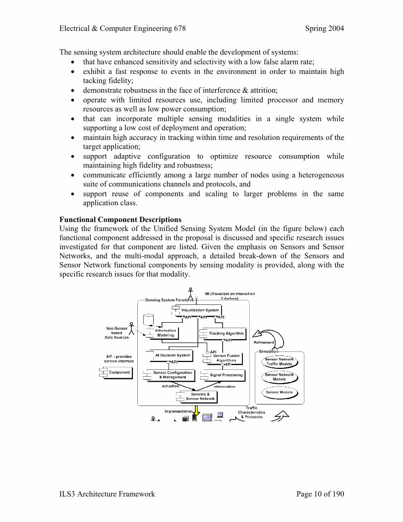
application class. Functional Component Descriptions Using the framework of the Unified Sensing System Model (in the figure below) each functional component addressed in the proposal is discussed and specific research issues investigated for that component are listed. Given the emphasis on Sensors and Sensor Networks, and the multi-modal approach, a detailed break-down of the Sensors and Sensor Network functional components by sensing modality is provided, along with the specific research issues for that modality.