architecture = design? the increasingly strong link ... · architecture = design? the increasingly...
TRANSCRIPT

1055
Proceedings of the IMProVe 2011
International conference on Innovative Methods in Product Design
June 15th – 17th, 2011, Venice, Italy
Architecture = Design?
The increasingly strong link between 3D modeling and automated manufacturing
M. Capone
University of Naples Federico II, Architecture, DICATA
Article Information
Keywords: Free-form geometry CAD\CAM Digital fabrication 3D modeling Reverse Modeling.
Corresponding author: Mara Capone Tel.:+39 0812538446 Fax.:+38 0812538406 e-mail: [email protected] Address: via Tarsia 31, Naples
Abstract
3D models have always been used to study and control complex shapes. The Luca Pacioli's vacuous models and Gaudi's funicular polygon are the best way to study geometry and to represent complex architecture. The 3D digital model offers advantages over the traditional material model, in fact it is able to simulate the perceptive dimension, to verify structures, but we can build from it, prototypes or architectural components too. The relationship between digital model and construction is very close, now we can produce prototypes, models or elements of construction using CAM technology, CNC systems or rapid prototyping. Development of these tools is increasingly approaching Architecture to Design not only regard on the forms, but regard on the design method. The new tools are profoundly changing the processes of design and construction and the boundaries between architecture, engineering and production methods are increasingly blurred. To examine the relationship between 3D modelling (real or digital models) and production methods, in our research we rebuilt 3D models of some very different study cases in which the relation between the real model, digital model and the construction of building's components are reversed.
1 Introduction 3D models have always been used to study and control
complex shapes. The Luca Pacioli's vacuous models and Gaudi's funicular polygon are the best way to study geometry and to represent complex architecture. The 3D digital model offers advantages over the traditional material model, in fact it is able to simulate the perceptive dimension, to verify structures, but it is possible build from it, prototypes or architectural components too. The relationship between digital model and construction is very close, now we can produce prototypes, models or elements of construction using CAM technology, CNC systems or rapid prototyping. Development of these tools is increasingly approaching Architecture to Design not only regard on the forms, but regard on the design method.
The new tools are profoundly changing the processes of design and construction and the boundaries between architecture, engineering and production methods are increasingly blurred.
The paper describes and examines the relationship between 3D modelling (real or digital models) and production methods. In our research we have chosen some very different case study in which the relation between the real model, digital model and the construction of building's components are reversed and we have rebuilt 3D model in some different ways to test different methodological paths. In particular our goal is to test the different rules of geometry in the construction of 3D digital model and in the design process. To do that, we analyzed two diametrically opposite ways to solve the problem of modelling and construction of a complex form: the design of the tower Kupla for the Korkeasaari Helsinki Zoo designed by Ville Hara and the Bubble BMW
pavilion designed by Bernard Franken and we tried to solve the same problems in different ways.
The Kupla is a unusual grid shell, whose shape is controlled by the designer using a physical model, from that he gets the digital model for structural design, through a process of reverse modelling. In this case from the physical model is constructed digital model and then using the same modelling principle, architecture is built. The strips that make up this architecture behave as "splines" and the shape of the tower is defined from the union of these lines "drawn in space". In this case geometry and structure coincide perfectly.
Very different is the case of Bernard Franken's BMW pavilion, it is an isomorphic architecture generated using a dynamic modelling process called metaballs, in this case the designer manufactures the component to construct the building directly from the digital model: this example shows how is increasingly strong the link between 3D model and automated manufacturing.
The paper also underlines how the typical methods of industrial design are progressively approaching to the world of architectural production.
2 From physical model to digital model Architects draw what they could build and build what
they could draw [1]. The representation form used to design a no-standard object, a free form geometry, is physical model that sometime can be a guide to manufacturing. In the digital era, the evolution of 3D fabrication technique and the real possibility to automatic manufacture of free form have encouraged the use of fully digital processes.
In many cases the design method is hybrid and many architects are used to fabricate a physical model to
1056
M. Capone Architecture = Design?
June 15th – 17th, 2011, Venice, Italy Proceedings of the IMProVe 2011
develop our idea. In these cases, to work in a digital environment it is necessary to survey the physical model and to rebuild a digital one. There are a lot of system to acquire and to generate 3D data, such as 3D laser scanner, all these systems are able to reconstruct a 3D object in a digital environment.
This process, called reverse modeling, is used when we'd like to fabricate a 3D digital model from an existing one. Many architects use reverse modeling process to design and to product architectural buildings, this method has been experimenting for many years in the Frank Gehry's Studio, but we decided to choose a very different case study. We chose an unusual gridshell designed by a very young architect, Ville Hara.
2.1 Case study: Tower Kupla by Ville Hara
Every year the Architecture Department of Helsinki University of Technology organizes a competition about innovative structural designs among its students. The competition asks for temporary structures, a nice pavilion on the beach, a small café on an empty lot in the city and so on, these types of buildings look like to the design objects rather than architecture and so they are very interesting cases study to investigate the relationship between Architecture and Design.
In 1999, the competition for students called for the construction of a lookout tower at Helsinki Zoo and it was sponsored by Korkeasari Zoo, Helsinki City.
The winning design was Kupla (bubble), the tower was a Ville Hara's graduation project and in 2003 it was chosen as the best project by the Archprix International committee [2].
Kupla is a free form gridshell where we can observe the perfect coincidence between structure and form. The form is created interweaving, bending and twisting 72 gluelam battens, and the shell structure is hold together by over 600 bolted joints. To control this free-form from January to May 2001, students at the Wood Studio workshop developed the draft design by assembling scale models and exploring structural details. The building of a big model made it possible to find solutions to the problems that came up at this stage and it saved from many unpleasant surprises during the construction phase [3].
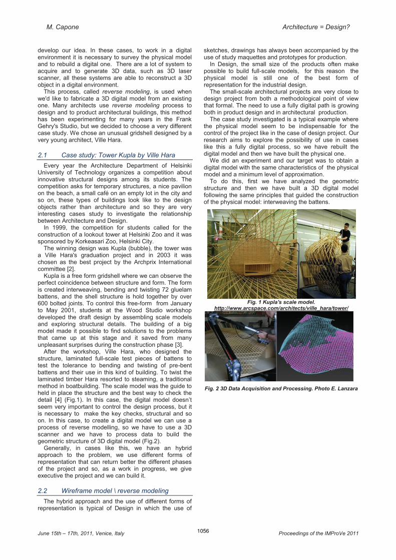
After the workshop, Ville Hara, who designed the structure, laminated full-scale test pieces of battens to test the tolerance to bending and twisting of pre-bent battens and their use in this kind of building. To twist the laminated timber Hara resorted to steaming, a traditional method in boatbuilding. The scale model was the guide to held in place the structure and the best way to check the detail [4] (Fig.1). In this case, the digital model doesn’t seem very important to control the design process, but it is necessary to make the key checks, structural and so on. In this case, to create a digital model we can use a process of reverse modelling, so we have to use a 3D scanner and we have to process data to build the geometric structure of 3D digital model (Fig.2).
Generally, in cases like this, we have an hybrid approach to the problem, we use different forms of representation that can return better the different phases of the project and so, as a work in progress, we give executive the project and we can build it.
2.2 Wireframe model \ reverse modeling
The hybrid approach and the use of different forms of representation is typical of Design in which the use of
sketches, drawings has always been accompanied by the use of study maquettes and prototypes for production.
In Design, the small size of the products often make possible to build full-scale models, for this reason the physical model is still one of the best form of representation for the industrial design.
The small-scale architectural projects are very close to design project from both a methodological point of view that formal. The need to use a fully digital path is growing both in product design and in architectural production.
The case study investigated is a typical example where the physical model seem to be indispensable for the control of the project like in the case of design project. Our research aims to explore the possibility of use in cases like this a fully digital process, so we have rebuilt the digital model and then we have built the physical one.
We did an experiment and our target was to obtain a digital model with the same characteristics of the physical model and a minimum level of approximation.
To do this, first we have analyzed the geometric structure and then we have built a 3D digital model following the same principles that guided the construction of the physical model: interweaving the battens.
Fig. 1 Kupla's scale model.
http://www.arcspace.com/architects/ville_hara/tower/
Fig. 2 3D Data Acquisition and Processing. Photo E. Lanzara

1057
M. Capone Architecture = Design?
June 15th – 17th, 2011, Venice, Italy Proceedings of the IMProVe 2011
Fig. 3 Kupla geometric hypothesis: all corresponded nodes are on the same plane. E. Lanzara graduation thesis.
Supervisor prof. M. Capone The digital model was developed according to a
methodology that can be defined as wire frame, so not as solid or surface modeling, because in this case there isn't a real surface but only an ideal surface. This kind of model reflects the origin of the digital representation and his first real innovative peculiarity: to allow us to draw lines in 3D space.
In this case it was essential to define some geometric assumptions that have guided the construction of the digital model. We hypothesized that: - initially the battens, that make up the structure, were
treated as 3D polylines, coincident with axis of the gluelam battens;
- the 3D polylines have been constructed by interpolating some points sure;
- some of this points are obtained by dividing the three floors and the eye in the same number of parts;
- all corresponded nodes are on the same plane. In this case the form is free, but still influenced by these
assumptions. So we constructed a digital model according to these hypotheses, and then: - the three floors and the inclined eye were positioned
at their own level and then we divided them into 37 equal parts and we determined the 36 anchor points of the 72 3D poly lines;
- the 3D polylines were constructed by interpolation using the points determined at the floors and the eye.
3D polylines intersect only in the anchor points at the floor, while they are placed at a variable distance in the rest of the model. The other nodes have been determined
Fig. 4 Kupla: 3D digital model. . E. Lanzara graduation thesis.
Supervisor prof. M. Capone
on the geometric assumption of coplanarity of the corresponding nodes.
In particular, we are identified three areas, two between the floors and third between the second floor and the inclined eye. Based on the number of nodes present in each band we have been built six equidistant horizontal planes in the first band, four in the second band and six inclined planes in the third band (Fig.3). To locate the nodes belonging to the third band that ends with the inclined eye we identified the line r, the intersection between the horizontal plane of the second floor and the inclined plan of the eye. The line r is a support axis of the plans sheaf that we used to define the nodes (Fig. 4).
To determine one of the nodes we considered the intersection between the 3D polylines and one of the plans.
Fig. 5 Intersection of 3D polyline with planes . . E. Lanzara graduation thesis. Supervisor prof. M. Capone
Fig. 6 3D polyline analysis. 3D model E. Lanzara graduation thesis. Supervisor prof. M. Capone

1058
M. Capone Architecture = Design?
June 15th – 17th, 2011, Venice, Italy Proceedings of the IMProVe 2011
Fig. 7 3D digital model:real axis real structure. 3D model E. Lanzara graduation thesis. Supervisor prof. M. Capone
Fig. 8 Kupla: our physical model. E. Lanzara graduation thesis. Supervisor prof. M. Capone. Photos E. Lanzara
Fig. 9 Kupla: structure and surface. 3D model E. Lanzara graduation thesis. Supervisor prof. M. Capone
We can verify that the 3D polylines intersect the plane
in two different points, A and B, the position of the center of the node in space is the midpoint of AB (Fig. 5) .
In this way we have defined the position in the space of the digital model of each node and so we built the 3D polylines that intersect at the nodes
To obtain an ideal surface continues we proceeded to analyze each and we removed discontinuities and inflection points (Fig. 6). To obtain the real axis of the battens we have to define a uniform distance of each axis from the corresponding node, this distance calculated according to the true thickness of the battens. The new 3D polylines that have this distance from the center of each node are the unifilars of the structure (fig.7).
To verify the similarity between this digital prototype and physical model we decided to reverse the Ville Hara process and we built a model in real scale to compare it with the digital model.
We built a physical model following the same path used to construct the digital one: we placed each floor at his own elevation, we interwined the battens and we fixed them to the anchor points on the floors, so we connected all the others intermediate nodes.
To verify some of our geometric hypothesis that we used to elaborate digital model, and in particular to verify
the coplanarity of the nodes, we built the virtual planes made of transparent material and so we was able to demonstrate the coplanarity of the nodes (Fig. 8).
We built a digital model very similar to physical one, so we have demonstrated that we could use our digital prototype in a manufacturing process.
Our target is also to demonstrate the fundamental role of geometry in the architectural and design project from the initial form-finding to the final construction, especially for the manufacturing of complex shape like this.
The case study was useful to demonstrate the possibility of applying a fully digital process to a particular type of building whose project approach is still tied to a traditional way based on the use of physical model as the best control tool both formal and structural aspect.
We believe it is essential to use a fully digital process to develop the product design but we also think that this method is very useful for some architecture projects, when they can be considered as a product of design.
Digital tools guided by the geometry always made it possible, in this case the search takes place on the border between applied geometry and design and tries to focus the most challenging problems.
3 From Digital model to Product The possibility of manufacturing a 3D object from a 3D
digital model, by using data generated from 3D software modeling, has opened new research and experimentation fields. The relationship between idea and production is completely changing in industrial design, automotive, shipbuilding where the digital production is already being used for a long time. This relationship is changing rapidly in architecture too [5].
To focus the possibility to apply digital manufacturing in the building industry, we have chose some study cases where some typical questions are more evident.
3.1 Case study: Franken's BMW pavilion
Completely different from Kupla is the case of BMW pavilion designed by Bernhard Franken for the 1999 International Motor Show in Frankfurt, that is one the best examples of a fully digital production process.
The concept is inspired by hydrogen-based technology, it is a free form that seems a drop of water and so it was called Bubble. As Kupla it was born as a temporary building, in fact, after two weeks at the Frankfurt Motor Show, the Bubble was dismantled, later was rebuilt at the Expo 2000 Presentation of BMW in Munich, where it was used as a café and club for another four months and in 2005 BMW decided to destroy the remains [6].
We are very interested in this case study because it is one of the first example of building fully designed and manufactured using digital tools.
The form was generated digitally, Franken used a dynamic process to express the balance between internal pressure and surface tension of a drop of water, he simulated a physical forces of two drops merging under the influence of gravity, and so the Bubble was generated [7]. As Kupla, this small pavilion looks like a design object rather than a building but in this case manufacturing method is very close to product design process and structural approach is very different.
The free-form architecture are generally characterized by a different relationship between structure an skin [8], unlike Kupla gridshell, in this case they are independent.
The approach in the BMW Bubble project is from the skin to the structure. The structural grid is obtained by

1059
M. Capone Architecture = Design?
June 15th – 17th, 2011, Venice, Italy Proceedings of the IMProVe 2011
Fig. 10 Bubble BMW: framework from 3D model. 3D model E. Lanzara graduation thesis. Supervisor prof. M. Capone
cutting the surface with horizontal and vertical planes orthogonal to each others. In this case the production strategy is based on the individuation of planar components from geometrically complex surface by using a sequence of planar section.
The sections of the object automatically generated from the 3D model are be processed by the structural analysis software to define the structural ribs of the pavilion (Fig. 10). The structural ribs are made of 3 layers of cut sheet aluminum. The section cutting was carried out using CNC-driven water-jet cutters in seven different factories, and the 3500 individual pieces were completed with required drill holes and assembly markings, so that the manual work on site for assembly could be reduced [8].
The first model of the Bubbles’ skin was constructed using a laser sintering method in the department for rapid prototyping at the design department of BMW. The 305 different acrylic-glass plates are produced using subtractive fabrication process, the CNC instruction are generated from 3D model to produce the formworks and so they were heat formed onto individually CNC milled foam blocks, and then trimmed at the edges, again with CNC [8](Fig. 11).
In this case study 3D digital model is first step to a continuous process from design till the manufacturing is executed digitally and we have represented the process (fig.10)
Fig. 11 Bubble BMW pavilion: product process. Photo www.digitalworks.it/UNI/PeS_2003_1/PeS%20lezione%2001/
introPes-mainframe03.htm
3.2 Structure vs Skin
In the free-form architecture the relationship between structure and skin can be solved in two very different ways: - the structure and skin are independent - structure is embedded in the skin.
In our cases study structure and skin are independent, this is clear for Bubble but it is obvious about Kupla because there isn't skin.
Very different are the cases in which structure is embedded in the skin, where we have an element that is able to absorb all the stresses.
In this cases, more than the others, the formal continuity isn't apparent but it is real and the concept method are very close to product design, especially about manufacturing.
The idea is to concept skin and structure as a unique element and so the research should test the relationship between form, geometry, new materials and new product technologies.
Some examples are very useful to demonstrate how technology and concepts can be borrowed the product methods from other industrial processes, such as automotive, aerospace and shipbuilding.
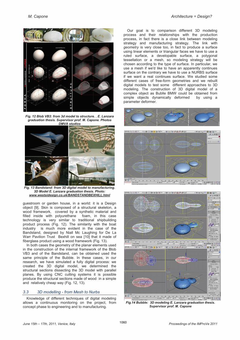
Blob VB3 by DMVA is one of these examples, projected in the 2010 it is a mobile unit for the office of xfactor agencies as an extension to the house, it easily transportable and can also be used as an office,
1060
M. Capone Architecture = Design?
June 15th – 17th, 2011, Venice, Italy Proceedings of the IMProVe 2011
Fig. 12 Blob VB3: from 3d model to structure. . E. Lanzara graduation thesis. Supervisor prof. M. Capone. Photos
DMVA studios
Fig. 13 Bandstand: from 3D digital model to manufacturing. 3D Model E. Lanzara graduation thesis. Photo:
www.westsidesign.co.uk/BANDSTANDBEXHILL.html
guestroom or garden house, in a world: it is a Design object [9]. Skin is composed of a structural skeleton, a wood framework, covered by a synthetic material and filled inside with polyurethane foam, in this case technology is very similar to traditional shipbuilding product process (Fig. 12). The similarity with the boat industry is much more evident in the case of the Bandstand, designed by Niall Mc Laughing for De La Warr Pavilion Trust Bexhill on sea [10] that it made of fiberglass product using a wood framework (Fig. 13).
In both cases the geometry of the planar elements used in the construction of the internal framework of the Blob VB3 and of the Bandstand, can be obtained used the same principle of the Bubble. In these cases, in our research, we have simulated a fully digital process: we created the 3D digital model, we determined the structural sections dissecting the 3D model with parallel planes. By using CNC cutting systems it is possible produce the structural sections made of wood in a simple and relatively cheap way (Fig. 12, 13).
3.3 3D modelling - from Mesh to Nurbs
Knowledge of different techniques of digital modeling allows a continuous monitoring on the project, from concept phase to engineering and to manufacturing.
Our goal is to comparison different 3D modeling process and their relationships with the production process, in fact there is a close link between modeling strategy and manufacturing strategy. The link with geometry is very close too, in fact to produce a surface using linear elements or triangular faces we have to use a ruled surface, a developable surface, a polygonal tessellation or a mesh, so modeling strategy will be chosen according to the type of surface. In particular, we use a mesh if we'd like to have an apparently continues surface on the contrary we have to use a NURBS surface if we want a real continues surface. We studied some different cases of free-form geometries and we rebuilt digital models to test some different approaches to 3D modeling. The construction of 3D digital model of a complex object as Bublle BMW could be obtained from simple objects dynamically deformed by using a parameter deformer.
Fig.14 Bubble: 3D modeling E. Lanzara graduation thesis.
Supervisor prof. M. Capone

1061
M. Capone Architecture = Design?
June 15th – 17th, 2011, Venice, Italy Proceedings of the IMProVe 2011
In this case we used 3ds Max software and additional software (plug in) called Clay Studio, because it is able to give appropriate parametric properties to objects. Specifically, the objects are surrounded by fields of Clay attraction capable of deforming the objects themselves when they are near the camp [11]. The software is able to generate automatically this surface. The second step to be constructible the form was to transform the mesh obtained, the Clay Surface, in a NURBS surface, and so in geometrically and numerically defined object that we can product using CNC technology (Fig. 14).
In this case structure and skin are independent and we determined the geometry of structure grid from the 3D digital model.
Unlike the case of the Blob VB3, where we used NURBS modeling. We started from a primitive transformed in a NURBS surface, than we deformed that surface using a control box. The 3D box lets us to change an entity and to monitor this change by using some control points in 3D space. We can check the transformation of the NURBS surface even by using same control points that are on a plane. In a fully digital product process we can determinate the planar element of the structural skin automatically by cutting the 3D digital model (Fig. 12).
To construct the 3D digital model of the Bandstand we used thinkdesign software, by THINK3, and another modeling technique called GSM (Global System Modeling) that has enabled to generate the form by transforming a plane. By using this modeling technique we can transform any object adding new elements or modifying an existing one. Thanks to the advanced GSM command you can change the space, or apply changes to points, surfaces, curves and any items contained in the graphics from an initial shape in a change controlled through a global modeling. The key point is therefore a completely different formulation of the geometric model: in fact, the method overcomes the difficulty of the local modeling typical of the NURBS surfaces and the control points. It is also able to verify that the transaction details of the composition of preserves, without additional corrective operations, the boundary conditions of continuity and tangency. The GSM allows you to change the overall shape of any object type, even if it is very complex, and for this reason it is a modeling technique used particularly in the automotive industry and mechanical design and production (Fig. 15).
Also in this case, geometry of the structural elements to product the framework was derived from 3D model.
The case studies show that to different approaches to modeling of complex shapes not always correspond different approaches to manufacturing.
3.4 From design to production
Some architects, such as Bernhard Franken, are pursuing a so-called digital architecture, a medial concept featuring a coherent digital process from design to production. Starting out on a creative idea both form and product developed digitally, they are exploring potentiality in the architectural production.
The most advances in digital design is the possibility to directly translated 3D model into tangible three-dimensional form. This is possible by using a computer numerically controlled (CNC) fabrication processes, that are able to product elements by cutting, subtractive, additive or formative systems [12].
We can be produced full-scale building components using data obtained automatically from digital models.
Product process is managed from digital representation and CAD/CAM technologies enable us to produce free form object in a easier an cheaper way.
So, the new digital fabrication techniques can be summarized:
CNC cutting or 2D fabrication subtractive fabrication additive fabrication formative fabrication The most used fabrication technique is CNC cutting,
characterized by different cutting technology such as plasma-arc, laser-beam and water-jet. Using this system we can product planar components, such as the aluminium framework of the Bubble BMW that is cut directly from digital data using CNC water-jet technology, and in the same way we can fabricate the inside elements of the free-form's structural skin that we analyzed.
Subtractive fabrication technique is based on removing material from a solid using different technology such as electronic, chemical or mechanical system. We have just observed how this technology has been applied to produce the formwork to fabricate the double-curved acrylic glass panel for Franken's Bubble BMW pavilion.
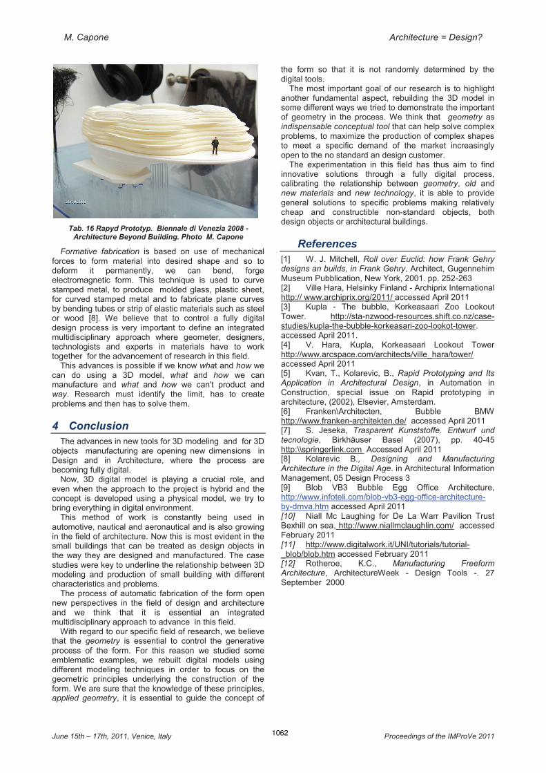
Additive fabrication, or Rapid Prototyping (RP), is based on adding material in a layer by layer process, to produce a physical model of the form generated by the parametric model. RP system uses the STL file generate by 3D modeling software to fabricate plastic, ceramic and metal object or to produce prototypes and architectural presentation model (Fig. 16).
This product process is used in design but the application in building production are still limited.
Several experimentation are made to produce some buildings components, as free form structural elements, but the most interesting application are based on sprayed concrete systems that are able to manufacture buildings parts directly from digital data. The concept is to have a 3D Printer that's able to print out layer after layer a building part and, someday, all the building [8].
Fig. 15 Bandstand: from 3D model to structure. 3D model E.
Lanzara graduation thesis. Supervisor prof. M. Capone
1062
M. Capone Architecture = Design?
June 15th – 17th, 2011, Venice, Italy Proceedings of the IMProVe 2011
Tab. 16 Rapyd Prototyp. Biennale di Venezia 2008 - Architecture Beyond Building. Photo M. Capone
Formative fabrication is based on use of mechanical forces to form material into desired shape and so to deform it permanently, we can bend, forge electromagnetic form. This technique is used to curve stamped metal, to produce molded glass, plastic sheet, for curved stamped metal and to fabricate plane curves by bending tubes or strip of elastic materials such as steel or wood [8]. We believe that to control a fully digital design process is very important to define an integrated multidisciplinary approach where geometer, designers, technologists and experts in materials have to work together for the advancement of research in this field.
This advances is possible if we know what and how we can do using a 3D model, what and how we can manufacture and what and how we can't product and way. Research must identify the limit, has to create problems and then has to solve them.
4 Conclusion The advances in new tools for 3D modeling and for 3D
objects manufacturing are opening new dimensions in Design and in Architecture, where the process are becoming fully digital.
Now, 3D digital model is playing a crucial role, and even when the approach to the project is hybrid and the concept is developed using a physical model, we try to bring everything in digital environment.
This method of work is constantly being used in automotive, nautical and aeronautical and is also growing in the field of architecture. Now this is most evident in the small buildings that can be treated as design objects in the way they are designed and manufactured. The case studies were key to underline the relationship between 3D modeling and production of small building with different characteristics and problems.
The process of automatic fabrication of the form open new perspectives in the field of design and architecture and we think that it is essential an integrated multidisciplinary approach to advance in this field.
With regard to our specific field of research, we believe that the geometry is essential to control the generative process of the form. For this reason we studied some emblematic examples, we rebuilt digital models using different modeling techniques in order to focus on the geometric principles underlying the construction of the form. We are sure that the knowledge of these principles, applied geometry, it is essential to guide the concept of
the form so that it is not randomly determined by the digital tools.
The most important goal of our research is to highlight another fundamental aspect, rebuilding the 3D model in some different ways we tried to demonstrate the important of geometry in the process. We think that geometry as indispensable conceptual tool that can help solve complex problems, to maximize the production of complex shapes to meet a specific demand of the market increasingly open to the no standard an design customer.
The experimentation in this field has thus aim to find innovative solutions through a fully digital process, calibrating the relationship between geometry, old and new materials and new technology, it is able to provide general solutions to specific problems making relatively cheap and constructible non-standard objects, both design objects or architectural buildings.
References [1] W. J. Mitchell, Roll over Euclid: how Frank Gehry designs an builds, in Frank Gehry, Architect, Gugennehim Museum Pubblication, New York, 2001. pp. 252-263 [2] Ville Hara, Helsinky Finland - Archiprix International http:// www.archiprix.org/2011/ accessed April 2011 [3] Kupla - The bubble, Korkeasaari Zoo Lookout Tower. http://sta-nzwood-resources.shift.co.nz/case-studies/kupla-the-bubble-korkeasari-zoo-lookot-tower. accessed April 2011. [4] V. Hara, Kupla, Korkeasaari Lookout Tower http://www.arcspace.com/architects/ville_hara/tower/ accessed April 2011 [5] Kvan, T., Kolarevic, B., Rapid Prototyping and Its Application in Architectural Design, in Automation in Construction, special issue on Rapid prototyping in architecture, (2002), Elsevier, Amsterdam. [6] Franken\Architecten, Bubble BMW http://www.franken-architekten.de/ accessed April 2011 [7] S. Jeseka, Trasparent Kunststoffe. Entwurf und tecnologie, Birkhäuser Basel (2007), pp. 40-45 http:\\springerlink.com Accessed April 2011 [8] Kolarevic B., Designing and Manufacturing Architecture in the Digital Age. in Architectural Information Management, 05 Design Process 3 [9] Blob VB3 Bubble Egg Office Architecture, http://www.infoteli.com/blob-vb3-egg-office-architecture-by-dmva.htm accessed April 2011 [10] Niall Mc Laughing for De La Warr Pavilion Trust Bexhill on sea, http://www.niallmclaughlin.com/ accessed February 2011 [11] http://www.digitalwork.it/UNI/tutorials/tutorial-_blob/blob.htm accessed February 2011 [12] Rotheroe, K.C., Manufacturing Freeform Architecture, ArchitectureWeek - Design Tools -. 27 September 2000