architectural modeling and analysis for safety...
TRANSCRIPT
Architectural Modeling and Analysis for SafetyEngineering
Danielle Stewart1, Michael W. Whalen1, Darren Cofer2, and Mats P.E. Heimdahl1
1 University of MinnesotaDepartment of Computer Science and Engineering
whalen, dkstewar, [email protected] Rockwell Collins
Abstract. Architecture description languages such as AADL allow systems en-gineers to specify the structure of system architectures and perform several anal-yses over them, including schedulability, resource analysis, and information flow.In addition, they permit system-level requirements to be specified and analyzedearly in the development process of airborne and ground-based systems. Thesetools can also be used to perform safety analysis based on the system architectureand initial functional decomposition.Using AADL-based system architecture modeling and analysis tools as an ex-emplar, we extend existing analysis methods to support system safety objectivesof ARP4754A and ARP4761. This includes extensions to existing modeling lan-guages to better describe failure conditions, interactions, and mitigations, and im-provements to compositional reasoning approaches focused on the specific needsof system safety analysis. We develop example systems based on the Wheel Brak-ing System in SAE AIR6110 to evaluate the effectiveness and practicality of ourapproach.
Keywords: Model-based systems engineering, fault analysis, safety engineering
1 Introduction
System safety analysis techniques are well established and are a required activity in thedevelopment of commercial aircraft and safety-critical ground systems. However, thesetechniques are based on informal system descriptions that are separate from the actualsystem design artifacts, and are highly dependent on the skill and intuition of a safetyanalyst. The lack of precise models of the system architecture and its failure modesoften forces safety analysts to devote significant effort to gathering architectural detailsabout the system behavior from multiple sources and embedding this information insafety artifacts, such as fault trees.
While model-based development (MBD) methods are widely used in the aerospaceindustry, they are generally disconnected from the safety analysis process itself. For-mal model-based systems engineering (MBSE) methods and tools [3, 7, 8, 20, 21, 25]now permit system-level requirements to be specified and analyzed early in the devel-opment process. These tools can also be used to perform safety analysis based on the
system architecture and initial functional decomposition. Design models from whichaircraft systems are developed can be integrated into the safety analysis process to helpguarantee accurate and consistent results. This integration is especially important as theamount of safety-critical hardware and software in domains such as aerospace, automo-tive, and medical devices has dramatically increased due to desire for greater autonomy,capability, and connectedness.
Architecture description languages, such as SysML [10] and the Architecture Anal-ysis and Design Language (AADL) [1] are appropriate for capturing system safety in-formation. There are several tools that currently support reasoning about faults in ar-chitecture description languages, such as the AADL error annex [17] and HiP-HOPSfor EAST-ADL [6]. However, these approaches primarily use qualitative reasoning, inwhich faults are enumerated and their propagations through system components mustbe explicitly described. Given many possible faults, these propagation relationships be-come complex and it is also difficult to describe temporal properties of faults that evolveover time (e.g., leaky valve or slow divergence of sensor values).
In earlier work, University of Minnesota and Rockwell Collins developed anddemonstrated an approach to model-based safety analysis (MBSA) [13,15,16] using theSimulink notation [19]. In this approach, a behavioral model of (sometimes simplified)system dynamics was used to reason about the effect of faults. We believe that this ap-proach allows a natural and implicit notion of fault propagation through the changes inpressure, mode, etc. that describe the system’s behavior. Unlike qualitative approaches,this approach allows uniform reasoning about system functionality and failure behavior,and can describe complex temporal fault behaviors. On the other hand, Simulink is notan architecture description language, and several system engineering aspects, such ashardware devices and non-functional aspects cannot be easily captured in models.
This paper describes our initial work towards a behavioral approach to MBSA usingAADL. Using assume-guarantee compositional reasoning techniques, we hope to sup-port system safety objectives of ARP4754A and ARP4761. To make these capabilitiesaccessible to practicing safety engineers, it is necessary to extend modeling notations tobetter describe failure conditions, interactions, and mitigations, and provide improve-ments to compositional reasoning approaches focused on the specific needs of systemsafety analysis. These extensions involve creating models of fault effects and weavingthem into the analysis process. To a large extent, our work has been an adaptation of thework of Joshi et. al to the AADL modeling language.
To evaluate the effectiveness and practicality of our approach, we developed anarchitectural model of the Wheel Braking System model in SAE AIR6110. Startingfrom a reference AADL model constructed by the SEI instrumented with qualitativesafety analysis information [9], we added behavioral contracts to the model. In so doing,we determine that there are errors related to (manually constructed) propagations acrosscomponents, and also an architecture that contains single points of failure. We use ouranalyses to find these errors.
2 Example: Wheel Brake System
As a preliminary case study, we utilized the Wheel Brake System (WBS) describedin [2] (previously found in ARP4761 Appendix L). This ficticious aircraft system wasdeveloped to illustrate the design and safety analysis principles of ARP4754A andARP4761. The WBS is installed on the two main aircraft landing gears and is usedduring taxi, landing, and rejected take off. Braking is either commanded manually us-ing brake pedals or automatically by a digital control system with no need for the pedals(autobrake). When the wheels have traction, the autobrake function will provide a con-stant smooth deceleration.
Each wheel has a brake assembly that can be operated by two independent hydraulicsystems (designated green and blue). In normal braking mode, the green hydraulic sys-tem operates the brake assembly. If there is a failure in the green hydraulics, the systemswitches to alternate mode which uses the blue hydraulic system. The blue system isalso supplied by an accumulator which is a device that stores hydraulic pressure thatcan be released if both of the primary hydraulic pumps (blue and green) fail. The accu-mulator supplies hydraulic pressure in Emergency braking mode.
Switching between the hydraulic pistons and pressure sources can be commandedautomatically or manually. If the hydraulic pressure in the green supply is below acertain threshold, there is an automatic switchover to the blue hydraulic supply. If theblue hydraulic pump fails, then the accumulator is used to supply hydraulic pressure.
In both normal and alternate modes, an anti-skid capability is available. In the nor-mal mode, the brake pedal position is electronically fed to a computer called the BrakingSystem Control Unit (BSCU). The BSCU monitors signals that denote critical aircraftand system states to provide correct braking function, detect anomalies, broadcast warn-ings, and sent maintenance information to other systems.
2.1 Nominal System Model
The WBS AADL model of the nominal system behavior consists of mechanical anddigital components and their interconnections, as shown in Figure 1. The followingsection describes this nominal model from which the fault model was generated.
Wheel Braking System (WBS) The highest level model component is the WBS. It con-sists of the BSCU, green and blue hydraulic pressure lines (supplied by the green pumpand blue pump/accumulator respectively), a Selector which selects between normal andalternate modes of hydraulic pressure, and the wheel system. The WBS takes inputsfrom the environment including PedalPos1, AutoBrake, DecRate, AC Speed, and Skid.All of these inputs are forwarded to the BSCU to compute the brake commands.
Braking System Control Unit (BSCU) The BSCU is the digital component in the systemthat receives inputs from the WBS. It also receives feedback from the green and bluehydraulic lines and two power inputs from two separate power sources. The BSCU iscomposed of two command and monitor subsystems each powered independently fromseparate power sources. The pedal position is provided to these units and when skiddingoccurs, the command and monitor units will decrease the pressure to the brakes. The

Fig. 1. AADL Simple Model of the Wheel Brake System
command unit regulates the pressure to the brakes in the green hydraulic line throughthe command cmd nor. Computing this command requires both the brake requestedpower and the skid information. The command unit also regulates the pressure in theblue hydraulic line in order to prevent skidding which it does through the cmd alt com-mand. The monitor unit checks the validity of the command unit output.
The BSCU switches from normal to alternate mode (blue hydraulic system) whenthe output from either one of its command units is not valid or the green hydraulic pumpis below its pressure threshold. Once the system has switched into alternate mode, it willnot switch back into normal mode again.Once the system has switched into alternate mode, it will not switch into normal modeagain.
Hydraulic Pumps There are three hydraulic pumps in the system, green pump (normalmode), blue pump (alternate mode), and accumulator pump (emergency mode). Eachpump provides pressure to the system and is modeled in AADL as a floating point value.
Shutoff Valve The shutoff valve is situated between the green pump and the selector.It receives an input from the BSCU regarding valve position and regulates the pressurecoming through the green pipe accordingly.
Selector Valve The selector receives inputs from the pumps regarding pressure outputand the BSCU regarding which mode the system is in. It will output the appropriatepressure from green, blue, or accumulator pump. An added requirement of the selectorsystem is that it will only output pressure from one of these sources. Thus, the caseof having pressure supplied to the wheels from more than one pump is avoided. TheSelector takes the two pipe pressures (green and blue) as input, selects the system withadequate pressure and blocks the system with inadequate pressure. If both systems havepressure greater than the threshold, the AADL selects normal mode as the default.
Skid Valves The blue skid and green skid valves receive input from the selector aspressure coming through the respective pipes as well as input from the BSCU thatcommands normal or alternate mode. The skid valves will use these inputs to choosebetween the green or the blue pressure to send to the wheel.
2.2 Modeling Nominal System Behavior
In order to reason about behaviors of complex system architectures, we have developeda compositional verification tool for AADL models. Our tool, the Assume-GuaranteeReasoning Environment (AGREE) [8] is based on assume-guarantee contracts that canbe added to AADL components. The language used for contract specification is basedon the LUSTRE dataflow language [11]. The tool allows scaling of formal verifica-tion to large systems by splitting the analysis of a complex system architecture into acollection of verification tasks that correspond to the structure of the architecture.
We use AGREE to specify behavioral contracts corresponding to the behaviors ex-pected of each of the WBS components. An example of a contract is shown in Figure 2.
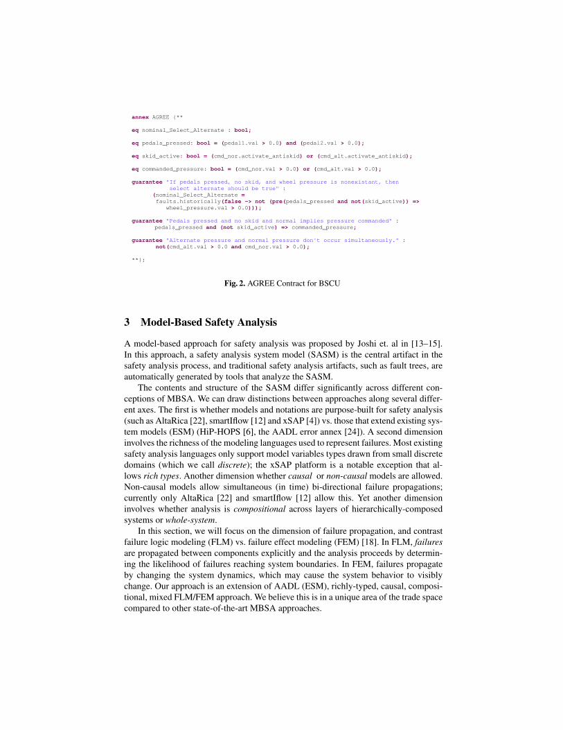
annex AGREE {** eq nominal_Select_Alternate : bool; eq pedals_pressed: bool = (pedal1.val > 0.0) and (pedal2.val > 0.0); eq skid_active: bool = (cmd_nor.activate_antiskid) or (cmd_alt.activate_antiskid); eq commanded_pressure: bool = (cmd_nor.val > 0.0) or (cmd_alt.val > 0.0); guarantee "If pedals pressed, no skid, and wheel pressure is nonexistant, then select alternate should be true" : (nominal_Select_Alternate = faults.historically(false -> not (pre(pedals_pressed and not(skid_active)) => wheel_pressure.val > 0.0))); guarantee "Pedals pressed and no skid and normal implies pressure commanded" : pedals_pressed and (not skid_active) => commanded_pressure; guarantee "Alternate pressure and normal pressure don't occur simultaneously." : not(cmd_alt.val > 0.0 and cmd_nor.val > 0.0); **};
Fig. 2. AGREE Contract for BSCU
3 Model-Based Safety Analysis
A model-based approach for safety analysis was proposed by Joshi et. al in [13–15].In this approach, a safety analysis system model (SASM) is the central artifact in thesafety analysis process, and traditional safety analysis artifacts, such as fault trees, areautomatically generated by tools that analyze the SASM.
The contents and structure of the SASM differ significantly across different con-ceptions of MBSA. We can draw distinctions between approaches along several differ-ent axes. The first is whether models and notations are purpose-built for safety analysis(such as AltaRica [22], smartIflow [12] and xSAP [4]) vs. those that extend existing sys-tem models (ESM) (HiP-HOPS [6], the AADL error annex [24]). A second dimensioninvolves the richness of the modeling languages used to represent failures. Most existingsafety analysis languages only support model variables types drawn from small discretedomains (which we call discrete); the xSAP platform is a notable exception that al-lows rich types. Another dimension whether causal or non-causal models are allowed.Non-causal models allow simultaneous (in time) bi-directional failure propagations;currently only AltaRica [22] and smartIflow [12] allow this. Yet another dimensioninvolves whether analysis is compositional across layers of hierarchically-composedsystems or whole-system.
In this section, we will focus on the dimension of failure propagation, and contrastfailure logic modeling (FLM) vs. failure effect modeling (FEM) [18]. In FLM, failuresare propagated between components explicitly and the analysis proceeds by determin-ing the likelihood of failures reaching system boundaries. In FEM, failures propagateby changing the system dynamics, which may cause the system behavior to visiblychange. Our approach is an extension of AADL (ESM), richly-typed, causal, composi-tional, mixed FLM/FEM approach. We believe this is in a unique area of the trade spacecompared to other state-of-the-art MBSA approaches.
3.1 Failure Logic Modeling (FLM) Approaches
The FLM approach focuses on faults rather than constructing a model of system dy-namics. We illustrate this approach with the AADL error model annex [24] that canbe used to describe system behaviors in the presence of faults. This annex has facil-ities for defining error types which can be used to describe error events that indicatefaults, errors, and failures in the system (the term error is used generically in the an-nex to describe faults, errors, and failures). The behavior of system components in thepresence of errors is determined by state machines that are attached to system compo-nents; these state machines can determine error propagations and error composition forsystems created from various subcomponents.
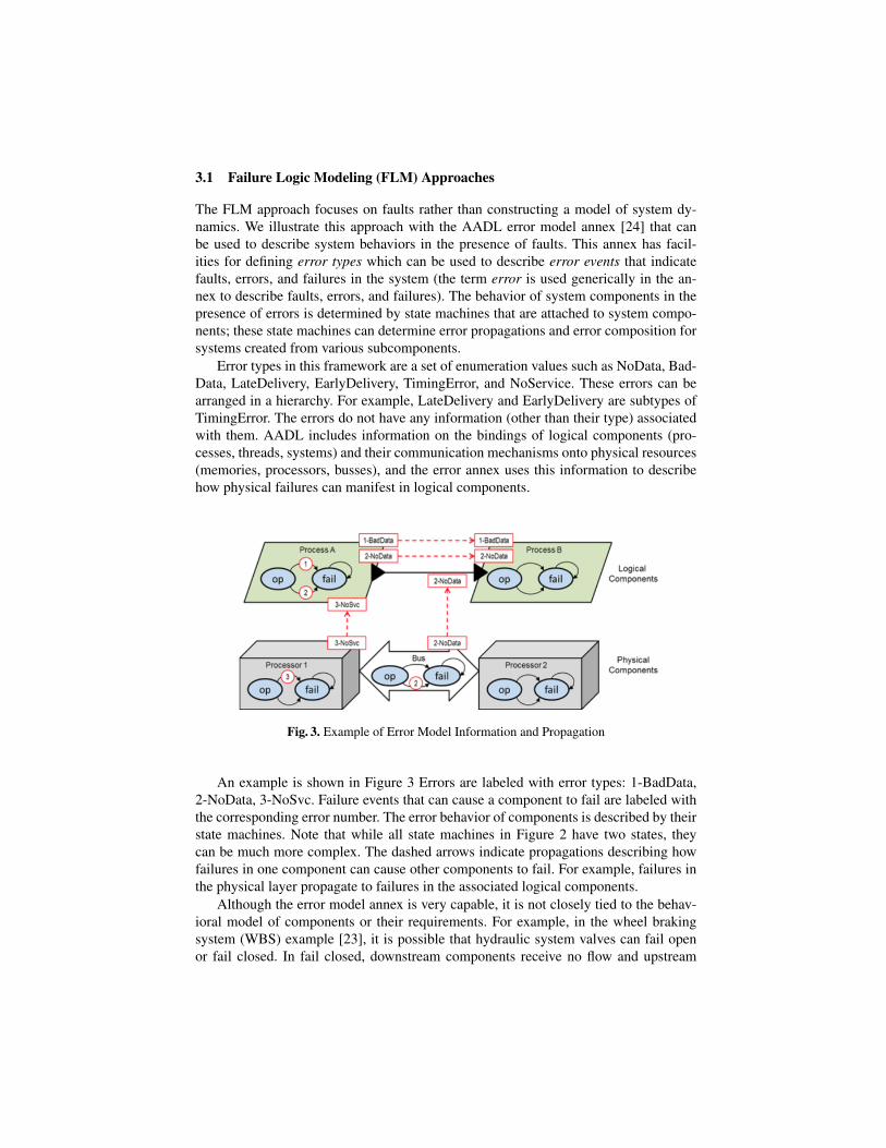
Error types in this framework are a set of enumeration values such as NoData, Bad-Data, LateDelivery, EarlyDelivery, TimingError, and NoService. These errors can bearranged in a hierarchy. For example, LateDelivery and EarlyDelivery are subtypes ofTimingError. The errors do not have any information (other than their type) associatedwith them. AADL includes information on the bindings of logical components (pro-cesses, threads, systems) and their communication mechanisms onto physical resources(memories, processors, busses), and the error annex uses this information to describehow physical failures can manifest in logical components.
Fig. 3. Example of Error Model Information and Propagation
An example is shown in Figure 3 Errors are labeled with error types: 1-BadData,2-NoData, 3-NoSvc. Failure events that can cause a component to fail are labeled withthe corresponding error number. The error behavior of components is described by theirstate machines. Note that while all state machines in Figure 2 have two states, theycan be much more complex. The dashed arrows indicate propagations describing howfailures in one component can cause other components to fail. For example, failures inthe physical layer propagate to failures in the associated logical components.
Although the error model annex is very capable, it is not closely tied to the behav-ioral model of components or their requirements. For example, in the wheel brakingsystem (WBS) example [23], it is possible that hydraulic system valves can fail openor fail closed. In fail closed, downstream components receive no flow and upstream
pipes may become highly pressurized as a natural consequence of the failure. Physicalmodels of these behavioral relationships often exist that can propagate failures in termsof the behavioral relationships between components. However, with the AADL errormodel annex, the propagations must be (re)specified and defined for each component.This re-specification can lead to inconsistencies between physical models and error an-nex models. In addition, the physical relationships between failures can be complex andmay not be describable using enumeration values, leading to additional inconsistenciesbetween the behavior of the physical phenomena and the behavior of the error model.
3.2 Failure Effect Modeling (FEM) Approaches
In a failure effect modeling approach, the analysis starts from a nominal model of thesystem that describes the system behavior when no faults are present. To perform safetyanalysis, we then also formalize the fault model. The fault model, in addition to com-mon failure modes such as non-deterministic, inverted, stuck at etc, could encode infor-mation regarding fault propagation, simultaneous dependent faults and fault hierarchies,etc. After specifying the fault model and composing it with the original system model,the safety analysis involves verifying whether the safety requirements hold in presenceof the faults defined in the fault model.
In this approach, a safety engineer can model different kinds of fault behavior: e.g.,stuck-at, ramp-up, ramp-down, and nondeterministic, and then weave these fault modelsinto the nominal model. The language for describing faults is extensible, allowing engi-neers to define a catalog of faults appropriate for their domain. In addition, the weavingprocess allows error propagation between unconnected components within a systemmodel [14]. This allows consideration of physical aspects (e.g., proximity of compo-nents, shared resources such as power) that may not be present in a logical systemmodel but can lead to dependent failures. In addition, it allows propagation of faults inthe reverse direction of the model data flow. This can occur when physical componentshave coupling such as back-pressure in fluid systems or power surges in the oppositedirection of communication through connected components. Finally, it is possible tocreate fault mediations to describe the output in the presence of multiple simultaneousfaults.
A safety analysis system model can be used for a variety of simulations and analy-ses. Modeling allows trivial exploration of what-if scenarios involving combinations offaults through simulations. The current AADL tool suite contains a graphical symbolicsimulator that allows for forward and back-stepping through different failure scenarios.In addition it contains a test-case generator that can automatically generate such sce-narios. For more rigorous analyses, we can use model checking tools to automaticallyprove (or disprove) whether the system meets specific safety requirements. As we willdemonstrate on the WBS, an engineer first verifies that safety properties hold on thenominal system, an idealized model of the digital controller and the mechanical systemcontaining no faults. Once the nominal model is shown to satisfy the safety property,the behavior of the fault-extended model can be examined to examine its resilience tofaults.
4 Architectural Failure Effect Modeling for the WBS
We illustrate our FEM approach on the Wheel Braking System. Starting from the nom-inal model described in Section 2.1, we first determine whether a given safety propertyof interest holds on a fault-free instance of the model. We then extend the model withfaults and determine whether the property continues to hold under reasonable fault sce-narios.
The initial safety property to be proven determines whether the system will applypressure to the wheels when commanded to do so:
If pedals are pressed and no skid occurs, then the brakeswill receive pressure.
Using the reference AADL model constructed by the SEI [9] extended with AGREEcontracts describing system behaviors, this property proves immediately. From thispoint, we focus our attention on component failures and how this will affect the toplevel property of the system.
We would like to specify different component failure modes. These failure modescan be triggered by some internal or propagated fault. In order to trigger these faults,additional input was added to the AADL model for each fault that can occur within anominal model component. This consists of two types:
– fail to fault: This type of fault accounts for both nondeterministic failures andstuck-at failures. The components that are affected by this fault include meter valvesand pumps. This fault can be used to describe both digital and mechanical errors.Examples of digital failures include a stuck at failure for the command subsystemin the BSCU component, which causes the command unit to become stuck at a pre-vious value. An example of a mechanical failure would be a valve stuck open (orclosed).
– inverted fail fault: This type of fault will be used on components which containboolean output. It will simply take boolean input, negate it, and output the negatedvalue. An example of this is the selector. In the nominal model, input to the selectorconsists of a boolean value select alternate value from the BSCU.
These faults can be easily encoded in AGREE as shown in Figure 4. The fail-ures simply return an alternate value (for fail to) or invert the input value (for in-verted failure) when a failure occurs.
While modeling faults, the duration of the fault must also be taken into account.The AGREE tools allow a great deal of flexibility in terms of how faults are defined andtheir duration. For the purposes of this model, we currently consider only transient andpermanent faults, where transient faults occur for an instant in time (e.g., a single-eventupset) and a permanent fault persists for the remainder of the system execution.
4.1 Analysis of Faulty Models
The following is a short summary of the failures defined in the fault model.

node fail_to(val_in: real, alt_val: real, fail_occurred: bool) returns (val_out: real); let val_out = if (fail_occurred) then alt_val else val_in;tel;
node inverted_fail(val_in: bool, fail_occurred: bool) returns (val_out:bool);let val_out = if fail_occurred then not(val_in) else val_in;tel;
Fig. 4. AGREE Definition of a fail to and inverted failure Faults
– Valves and Pumps: All valves and pumps have the possibility of a fail to fault. Thisincludes green pump, blue pump, accumulator, and the shutoff valves.
– The selector can also have a digital fail to fault regarding the inputs from BSCUcommanding to use normal or alternate means of pressure along with an in-verted fail fault which would change the boolean value that commands antiskidto activate.
Given our understanding of the WBS, our assumption was that any single permanentfault could be introduced into the system and the pilot would still be able to commandbrake pressure. However, our analysis tools returned a counterexample to the property,and upon examination, the structure of the reference model was insufficient to guaranteethe property.
The first issue was feedback; the reference model did not have a sensor to determinepressure after the selector valve. This means that a single failure of (for example) theblue or green antiskid valve cannot be detected by the BSCU (see Figure 1), and itcannot route around the failure. In order to address this, we added a pressure sensor tothe wheel that communicates with the BSCU to detect lack of pressure at the wheel.
After adding a sensing apparatus to the wheel, the analysis generated another coun-terexample due to a single failure of the selector valve. In the reference model, there isa single selector component that takes as inputs the green pump, the blue pump, and theaccumulator. A single failure in this component can lead to no pressure along either ofthe two outgoing pressure lines. To solve this issue, we removed the accumulator fromthe selector and added an accumulator valve. This component takes in the blue pres-sure from the selector and the accumulator pressure. It also takes in a select alternateflag from the BSCU. The output of the accumulator valve goes directly to the blue skidcomponent and is either the blue or the accumulator pressure.
Finally, our BSCU is currently structured to always fail-over from the green systemto the blue system but never the reverse. Because of this choice (which matches theAIR6110 document), it is also necessary to guarantee that select alternate is false untila failure occurs in the system; otherwise, a single failure in the blue anti-skid valve cancause the system to fail to provide pressure. This asymmetry is something that could berevisited in future work.
Even after making these three changes to the model, the original property still doesnot prove. At issue is that the sensing of a no-pressure situation is not instantaneous;there is a delay for this information to reach the BSCU and be acted upon to switch tothe alternate braking system. In our current timing model for the system, the feedbackto the BSCU involves a delay, but the BSCU and valves can react. Thus, we weakenour top-level property to state that if the brakes are pressed for two consecutive timeinstants, then pressure will be provided to the wheels:
If pedals are pressed in the previous state and pressedin the current state and no skid occurs, then the brakeswill receive pressure.
5 Discussion
We have used the WBS model as a vehicle to experiment with different modeling andfault representation ideas, and to get a feel for the scalability of our approach. We startedfrom the reference AADL model [9] to attempt to contrast our FEM approach usingAGREE contracts vs. the FLM-based approach that was already part of this model. Partof this was driven by curiosity as to whether important faults might be caught by oneapproach and missed by the other, and to contrast the two styles of analysis.
During the process of defining and injecting faults, subtle issues of the system struc-ture and behavioral interactions became much clearer. The idea that the system must usethe green side until a failure occurs was unexpected. In addition, the extensions to themodel were driven by the counterexamples returned by the tools. The approach quicklyand precisely provided feedback towards aspects of the system that were not robust tofailure. The researcher who produced the model (Danielle) was not involved in earlierMBSA work and had no prior exposure to the WBS model and yet was able to rela-tively quickly construct a fault-tolerant model. The fact that these holes in the referencemodel perhaps means that the behavioral approach can be better at drawing attention tocertain kinds of failures.
On the other hand, the utility of the safety analysis is driven by the “goodness” of theproperties. Our one example property is clearly insufficient: for example, it is not pos-sible to detect faults related to over-pressurization or misapplication of the brakes whenno braking is commanded. Of course, any complete analysis should have properties re-lated to each hazardous condition. The approach is foundationally a top-down analysis(like fault trees) rather than a bottom up approach (like a FMEA / FMECA). In addi-tion, if properties are mis-specified, or the system dynamics are incorrectly modeled,then properties may verify even when systems are unsafe. The explicit propagation ap-proach of the FLM techniques force the analyst to consider each fault interaction. Thistoo is a double-edged sword: when examining some of the fault propagations in thereference model, we disagreed with some of the choices made, particularly with respectto the selector valve. For example, if no select alternate commands are received fromthe BSCU, then both the green and blue lines emit a No Service failure.
In terms of scalability, the analysis time for counterexamples was on the order of1-2 seconds, and the time for proofs was around 4 seconds, even after annotating themodel with several different failures. Thus, we feel that the analysis is likely to scalewell to reasonably large models with many component failures.
The analysis in this paper involved hand-annotating the models with failure nodes.This process is both schematic and straightforward: we define the AGREE contractsover internal nominal output variables and then define the actual outputs using thenominal output variables as inputs to the fault nodes like those in Figure 4. We arecurrently in the process of defining a fault integration language. Some aspects of theError Annex could be directly relevant: the state machines describing leaf-level faultscould easily be compiled into behavioral state machines that determine when faultsoccur. On the other hand, in a behavioral approach we need to be able to bring inadditional quantities (inputs, parameters) to instantiate behavioral faults, and the twoapproaches have very different notions of propagation.
The xSAP tool [4] has an elegant extension language that allows for fault defini-tion, selection between multiple faults for a component, and “global” dependent faultsthat can affect multiple components. The authors have used this support to construct asophisticated analysis model for the WBS [5]. However, some useful aspects of faultmodeling, such as global faults that are driven by the state of the model, appear tobe hard to construct. For example, a pipe-burst failure can be seen as a global failurebecause it may cause unconnected components within the model to fail. On the otherhand, the likelihood of failure in the real system is driven by the number of currentlypressurized pipes in the system, which appears to be hard to define. We hope to allowfor such conditional and model-driven failures in our fault definition language.
6 Conclusions & Future Work
In this paper, we describe our initial work towards performing MBSA using the AADLarchitecture description language using a failure effect modeling approach. Our goal isto be able to perform safety analysis on common models used by systems and safety en-gineers for functional and non-functional analyses, schedulability, and perhaps systemimage generation. To perform this analysis, we use existing capabilities within AADLto describe the structure of the system, and build on the existing AGREE framework forcompositional analysis of components.
As part of our exploration, we are interested in examining the strengths and weak-nesses of our FEM and the AADL Error Annex FLM-based approach. We believe thatthe FEM approach has advantages both in terms of brevity of specifications and ac-curacy of results, and can build on existing analyses performed for systems engineer-ing. However, there are also risks in the FEM approach involving incomplete or mis-specified properties.
We illustrated the ideas using architecture models based on the Wheel Braking Sys-tem model in SAE AIR 6110 [2] and use this in the evaluation of our approach. Usingassume-guarantee compositional reasoning techniques, we prove a top level property ofthe wheel brake system that states when the brake pedals are pressed in the absence ofskidding, there will be hydraulic pressure supplied to the brakes.
Starting from the error model notions of error types, two main faults were defined:fail to which will describe failures of valves and pressure regulators and inverted failwhich describes the failures occurring to components that output boolean values. Usingthe AADL behavioral model of the WBS, these permanent faults were tied into thenominal model in order to reason about how this model behaves in the presence ofspecific kinds of faults.
In order to demonstrate that the system was resilient to single faults, we modified themodel to allow feedback from the wheel pressure to the BSCU. This changed the waythe system responded to faults that were further downstream of the BSCU or Selectorand created a chance for the system to switch to alternate forms of hydraulic pressure.We also reasoned about the initialization values of the system in regards to which modeis the starting mode. It is crucial for the system to begin in Normal mode in order tofunction successfully in the presence of faults. After model modification and a smallweakening of our original property to account for feedback delay, the model does fulfillthe top level contract even when a permanent fault of one of the high level componentsis introduced.
The current capabilities of AGREE are well-suited to specifying faults. Our ap-proach allows for scalar types of unbounded integers and reals, as well as compositetypes such as tuples and structures. It is possible to model systems and reason aboutthem in either discrete time or real-time. However, adding faults to existing compo-nents is cumbersome and can obscure the nominal behaviors of the model. We arecurrently examining several fault specification languages, giving special considerationto the xSAP modeling language.
Future research work will involve the continuation of development of the methodsand tools needed to perform model-based safety analysis at the system architecturelevel. By introducing a common set of models for both nominal system design andsafety analysis, we hope to reduce the cost of development and improve safety. Ourhope is to demonstrate the practicality of formal analysis for early detection of safetyissues that would be prohibitively expensive to find through testing and inspection. Wewill base this research on industry standard notations that are being used in airborneand ground-based avionics in order to ensure transition of this technology.
Acknowledgements
This research was funded by NASA AMASE NNL16AB07T.
References
1. AADL. Predictable Model-Based Engineering.2. AIR 6110. Contiguous Aircraft/System Development Process Example, Dec. 2011.3. J. Backes, D. Cofer, S. Miller, and M. W. Whalen. Requirements Analysis of a Quad-
Redundant Flight Control System. In K. Havelund, G. Holzmann, and R. Joshi, editors,NASA Formal Methods, volume 9058 of Lecture Notes in Computer Science, pages 82–96.Springer International Publishing, 2015.
4. B. Bittner, M. Bozzano, R. Cavada, A. Cimatti, M. Gario, A. Griggio, C. Mattarei,A. Micheli, and G. Zampedri. The xSAP Safety Analysis Platform. In Tools and Algorithmsfor the Construction and Analysis of Systems - 22nd International Conference, TACAS 2016,Held as Part of the European Joint Conferences on Theory and Practice of Software, ETAPS2016, Eindhoven, The Netherlands, April 2-8, 2016, Proceedings, pages 533–539, 2016.
5. M. Bozzano, A. Cimatti, A. F. Pires, D. Jones, G. Kimberly, T. Petri, R. Robinson, andS. Tonetta. Formal Design and Safety Analysis of AIR6110 Wheel Brake System. In Com-puter Aided Verification - 27th International Conference, CAV 2015, San Francisco, CA,USA, July 18-24, 2015, Proceedings, Part I, pages 518–535, 2015.
6. D. Chen, N. Mahmud, M. Walker, L. Feng, H. Lnn, and Y. Papadopoulos. Systems Modelingwith EAST-ADL for Fault Tree Analysis through HiP-HOPS*. IFAC Proceedings Volumes,46(22):91 – 96, 2013.
7. A. Cimatti and S. Tonetta. Contracts-Refinement Proof System for Component-Based Embedded System, journal = Sci. Comput. Program., volume = 97, pages= 333–348, year = 2015, url = http://dx.doi.org/10.1016/j.scico.2014.06.011, doi =10.1016/j.scico.2014.06.011, timestamp = Fri, 30 Jan 2015 18:56:15 +0100, biburl =http://dblp.uni-trier.de/rec/bib/journals/scp/CimattiT15, bibsource = dblp computer sciencebibliography, http://dblp.org.
8. D. D. Cofer, A. Gacek, S. P. Miller, M. W. Whalen, B. LaValley, and L. Sha. CompositionalVerification of Architectural Models. In A. E. Goodloe and S. Person, editors, Proceedingsof the 4th NASA Formal Methods Symposium (NFM 2012), volume 7226, pages 126–140,Berlin, Heidelberg, April 2012. Springer-Verlag.
9. J. Delange, P. Feiler, D. P. Gluch, and J. Hudak. AADL Fault Modeling and Analysis Withinan ARP4761 Safety Assessment. Technical Report CMU/SEI-2014-TR-020, Software En-gineering Institute: Carnegie Mellon University, October 2014.
10. S. Friedenthal, A. Moore, and R. Steiner. A Practical Guide to SysML. Morgan KaufmanPub, 2008.
11. N. Halbwachs, P. Caspi, P. Raymond, and D. Pilaud. The Synchronous Dataflow Program-ming Language Lustre. In In Proceedings of the IEEE, volume 79(9), pages 1305–1320,1991.
12. P. Hnig, R. Lunde, and F. Holzapfel. Model Based Safety Analysis with smartIflow . Infor-mation, 8(1), 2017.
13. A. Joshi and M. P. Heimdahl. Model-Based Safety Analysis of Simulink Models UsingSCADE Design Verifier. In SAFECOMP, volume 3688 of LNCS, page 122, 2005.
14. A. Joshi and M. P. Heimdahl. Behavioral Fault Modeling for Model-based Safety Analysis.In Proceedings of the 10th IEEE High Assurance Systems Engineering Symposium (HASE),2007.
15. A. Joshi, S. P. Miller, M. Whalen, and M. P. Heimdahl. A Proposal for Model-Based SafetyAnalysis. In In Proceedings of 24th Digital Avionics Systems Conference (Awarded BestPaper of Track), 2005.
16. A. Joshi, M. Whalen, and M. P. Heimdahl. Automated Safety Analysis Draft Final Report.Report for NASA Contract NCC-01001, August 2005.
17. B. Larson, J. Hatcliff, K. Fowler, and J. Delange. Illustrating the AADL Error ModelingAnnex (V.2) Using a Simple Safety-critical Medical Device. In Proceedings of the 2013ACM SIGAda Annual Conference on High Integrity Language Technology, HILT ’13, pages65–84, New York, NY, USA, 2013. ACM.
18. O. Lisagor, T. Kelly, and R. Niu. Model-based safety assessment: Review of the disciplineand its challenges. In The Proceedings of 2011 9th International Conference on Reliability,Maintainability and Safety, pages 625–632, June 2011.
19. MathWorks. The MathWorks Inc. Simulink Product Web Site.http://www.mathworks.com/products/simulink, 2004.
20. A. Murugesan, M. W. Whalen, S. Rayadurgam, and M. P. Heimdahl. Compositional Verifica-tion of a Medical Device System. In ACM Int’l Conf. on High Integrity Language Technology(HILT) 2013. ACM, November 2013.
21. M. Pajic, R. Mangharam, O. Sokolsky, D. Arney, J. Goldman, and I. Lee. Model-DrivenSafety Analysis of Closed-Loop Medical Systems. Industrial Informatics, IEEE Transac-tions on, PP:1–12, 2012. In early online access.
22. T. Prosvirnova, M. Batteux, P.-A. Brameret, A. Cherfi, T. Friedlhuber, J.-M. Roussel, andA. Rauzy. The AltaRica 3.0 Project for Model-Based Safety Assessment. IFAC ProceedingsVolumes, 46(22):127 – 132, 2013.
23. SAE ARP 4761. Guidelines and Methods for Conducting the Safety Assessment Process onCivil Airborne Systems and Equipment, December 1996.
24. SAE AS 5506B-3. Aadl annex volume 1, Sept. 2015.25. O. Sokolsky, I. Lee, and D. Clarke. Process-Algebraic Interpretation of AADL Models. In
Reliable Software Technologies - Ada-Europe 2009, 14th Ada-Europe International Confer-ence, Brest, France, June 8-12, 2009. Proceedings, pages 222–236, 2009.