architectural evolution of transport provider networks network management functions base services...
TRANSCRIPT

Architectural Evolution of Transport Provider Networks
Randy Zhang
BRKSPG-2525

• Transport providers’ challenges and solutions
• Agile lambda layer
• 100G and beyond
• Sub-lambda grooming
• Multilayer convergence and orchestration
Agenda

0
5
10
15
20
25
30
35
40
0
500
1000
1500
2000
2500
2013 2014 2015 2016 2017 2018 2019
Annual global IP Traffic (EB) Monthly Per User Traffic (GB)
Traffic Growth Continues
Source: Cisco VNI
Compounded
Annual Growth
Rate: 23%
Compounded
Annual Growth
Rate: 19%

Traffic Outpaces Revenue
Global Service Provider Data
2005–2012 Compound Annual
Growth Rate (CAGR)
Revenue Growth 5%
Capex Growth 5%
Bandwidth Growth 30%–70%
Infonetics Research, Inc 2014

The Provider Dollar Gap
What should operators do:
• Generate new sources of revenue or increase service velocity
• Reduce cost via incremental changes:
• Controlling Capex while growing capacity
• Opex reduction
• Improving utilization
• Reduce cost via architectural changes:
• Converging layers and products
• Application driven programmability
• Virtualization
Declining
Revenue
per bit
Exponential
Traffic Growth

Business Challenges
Risk Growth
Cost
Experience
Success
ProfitabilityReputation
• Network Simplification:
Expense Reduction ~20%
• Service innovation: ~17%
new revenue
• Agility: Service creation
from quarters to days

What solutions are available to meet these business challenges?

Grow Network Capacity and Agility…
• Integrate wavelength layer with high-degrees of wavelength division multiplexing
• Increase number of wavelengths and spectral bandwidth per fiber
• Increase per wavelength bit rate
• Create a mesh network with any to any connectivity
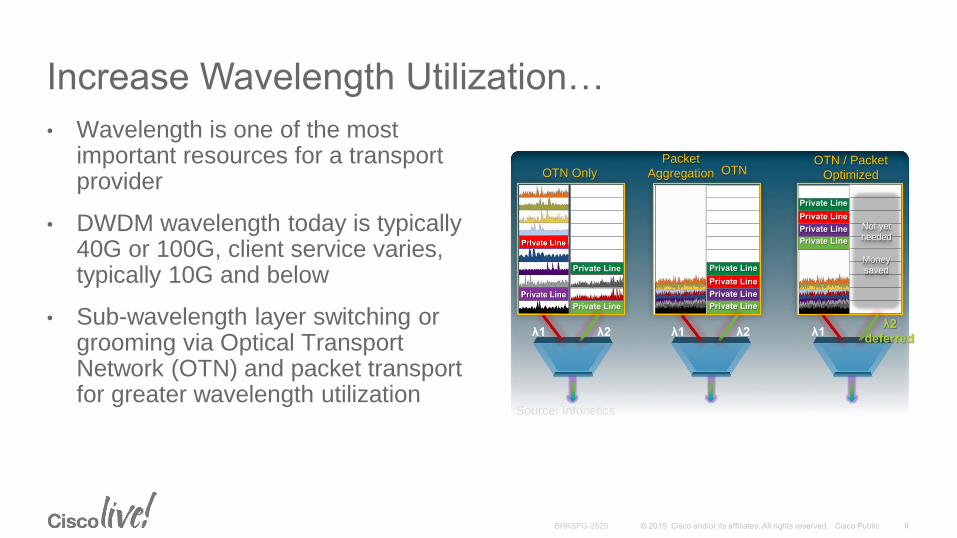
Increase Wavelength Utilization…
• Wavelength is one of the most important resources for a transport provider
• DWDM wavelength today is typically 40G or 100G, client service varies, typically 10G and below
• Sub-wavelength layer switching or grooming via Optical Transport Network (OTN) and packet transport for greater wavelength utilization
Source: Infonetics
OTN Only Packet
Aggregation OTN OTN / Packet
Optimized
Private Line
Private Line
Private Line
Private Line
Not yet needed
Money saved
λ2 λ1 λ2 λ1 λ2
deferred λ1
Private Line
Private Line
Private Line
Private Line
Private Line
Private Line
Private Line
Private Line
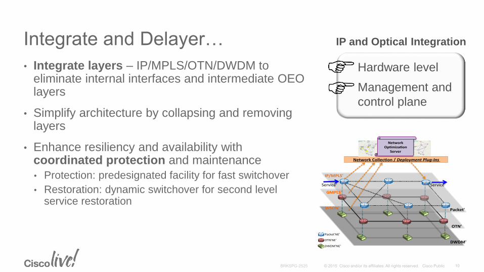
Integrate and Delayer…
• Integrate layers – IP/MPLS/OTN/DWDM to eliminate internal interfaces and intermediate OEO layers
• Simplify architecture by collapsing and removing layers
• Enhance resiliency and availability with coordinated protection and maintenance
• Protection: predesignated facility for fast switchover
• Restoration: dynamic switchover for second level service restoration
IP and Optical Integration
Hardware level
Management and
control plane
Packet'
OTN'
DWDM'
IP/MPLS'
GMPLS'
WSON'
Service' Service'
Packet'NE'
OTN'NE'
DWDM'NE'
NetworkCollec on/DeploymentPlug-Ins
NetworkOp miza on
Server

Automate…
• Automate manual processes and reduce service turn-up time
• Virtualization: OS, topology and service
• Use dynamic control plane for service provisioning
• Application programmable
• Multilayer and multidomain orchestration
Base Network Management Functions
Base Services Functions
SNMP OpenFlow NetconfHTTP/XML
Protocol Abstraction Layer
Device Access Functions
DB
Inventory ConfigTopology Fault Assurance SW Mgmt
North Bound APIs
Service Management Functions

Preserve What Is
Working
• Resiliency
• Scale
• Rich feature set
Achieve Business
Objectives
• Service agility and
velocity
• Simplified operations
• Higher value services
A Winning Strategy
Evolve for Emerging
Requirements
• Automation
• Convergence
• Virtualization
• Application interaction
+ =
Evolved Programmable Networks

Wavelength (L0)
SONET/SDH (L1)
Network Layers of Transport Providers
Alien
WavelengthsFC
ESCON
IP
IP
IPIP
TDM Voice TDM Private Line
IP/MPLS (L3/L2.5)
Ethernet (L2)
Optical Transport Network (L1)

Key Attributes of Next Generation Transport Architectures
• A wavelength layer that is agile and of high capacity:
• Reconfigurable any to any connectivity without blocking
• 100G and beyond per channel with flexible wavelength structure
• Sub-lambda layer switching to increase wavelength utilization
• Multilayer convergence: IP and optical convergence
• Multilayer orchestration: automation, programmability, and virtualization

Agile Lambda Layer

Fiber Optics and Wavelength Division
• Wavelength Division Multiplexing (WDM)
• Dense WDM (DWDM): >= 32 channels
• Coarse WDM (CWDM): <= 16 channels
• Terminology: wavelength, frequency, lambda, channel, color
Frequency (THz)
Wavelength (nm)196.2
1528.77
190.1
1578.23
50 GHz
.4 nm
193.1
1552.52
ITU Wavelength Grid
Fiber
𝑖=1
𝐶ℎ 𝑐𝑜𝑢𝑛𝑡
𝑏𝑖𝑡 𝑟𝑎𝑡𝑒 𝑎𝑡 𝐶ℎ 𝑖
Fiber traffic capacity

Communication WavelengthsL Band
C Band
S Band
Long reach
Short reach
Intermediate reach
UltraViolet InfraRedVisible
800 900 1000 1100 1200 1300 1400 1500 1600Wavelength (nm)
0.2
0.5
2.0
Loss (dB)/km

Point to Point DWDM Network
OEOTx
Rx
Tx
Rx
OAOA
Transponder
OEO
Tx
Rx
Tx
Rx
ClientITU Wavelengths Transponder Client
OEO: Optical-Electrical-Optical conversion
OA: Optical Amplifier
OEO OEO
* Showing one direction

Optical Add/Drop Multiplexer(OADM)
• Channels are added to or dropped from the network
• Some channels are passed through (expressed)
Add Channel
Drop Channel
* Showing one direction
Site 1
Site 2

Fixed OADM (FOADM)
• Network topology and channel capacity at each node are fixed at network design time
• Changing topology and capacity requires physical change (truck roll) and retuning, and results in service outage
• Need multiple spares, as the FOADM units are wavelength specific
• Traffic forecast may not be accurate
• Network hard to maintain
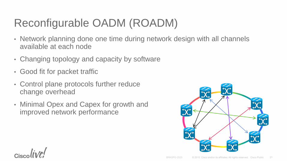
Reconfigurable OADM (ROADM)
• Network planning done one time during network design with all channels available at each node
• Changing topology and capacity by software
• Good fit for packet traffic
• Control plane protocols further reduce change overhead
• Minimal Opex and Capex for growth and improved network performance

ROADM in a Nutshell
Pass
Pass
Add
Add
Express
Line Out
Local Add
Splitter
drop block blockdrop
Local Drop
Line In
* Showing one direction
Wavelength Selective
Switch (WSS)
Per channel selection controlled by software

First Generation ROADM
• Pass-through channels are reconfigurable at all intermediate points.
• Manual change at Add/Drop points
• Colored: fixed wavelength assigned to an Add/Drop port with a patch cable, changing wavelength requires moving cables between transponder and mux/demux
• Directional: a mux/demux combo is assigned to a fixed line direction
• 2 degree nodes only
• 100 GHz spacing

Colored and Directional ROADM
East
West
Fixed wavelength on
Mux and Demux ports
Fixed direction for Add
and Drop
Demux Mux DemuxMux
WSS
Split WSS
Split
EastWest

The Cases for Colorless and Directionless ROADM
• Mesh network
• Bandwidth on-demand
• Dynamic restoration

Colorless and Directionless ROADM
WSS
Split
Degree A
WSS
Split
Degree B
WSS
Split
Degree C
WSS WSS
Patch Panel
Add Drop
Color selective at
Add/Drop with WSS
All degrees available at
Add/Drop
C
A B

Contentionless ROADM, Flexible Grid and Modulations
Contentionless ROADM Flexible Grid ROADM Flexible Modulations
NxM Switch
N degrees
M Add/Drop Ports
Any color from a degree can be dropped or added to any port
1 -
Odd
1-
Even
2 -
Odd
2 -
Even
3 -
Odd
3 -
Even
4 -
Odd
4-
Even
5 -
Odd
5 -
Even
6 -
Odd
6 -
Even
7 -
Odd
10
0 G
bp
s
40
0 G
bp
s
1 T
bp
s
10
0 G
bp
s
1 T
bp
s
10
0 G
bp
s
Not limited by ITU Grid (gridless) to form super channels
Choice of modulations based on bit rate and distance

DWDM Control and Management Planes
• Wavelength Switched Optical Network (WSON):
• LSP = wavelength; optical impairments awareness
• Dynamic light path setup, re-routing and restoration; programmable
• Automatic Power Control (APC):
• Automatically regulates amplifier and attenuator for capacity change, aging effects, operating conditions
• Cisco Transport Planner (CTP):
• DWDM design and planning tool
• Automatic Network Setup (ANS):
• CTP assisted network turn-up

Summary
• Today’s traffic requires fully flexible wavelength layer
• New generations of ROADMs provide the agility with:
• Colorless, Directionless, Contentionless (CDC)
• Flexible grid
• Dynamic control plane and management plane lead to simplified operations: WSON, APC, CTP, ANS
NCS 2000

100G and Beyond

Drivers for 100G DWDM
• Relieving fiber exhaustion due to wide deployment of 10G clients
• Continued increase of client rates
• Power and space saving: potentially more than 50% reduction in carbon footprint in a 10-year lifecycle (than 10G)
• Operational efficiency: Lower cost of managing and maintaining reduced number of boxes and links
• Better trunk utilization without resorting to load sharing with lower speed links
• Reducing overall network latency: Coherent receivers eliminate the extra fiber due to dispersion compensation

Requirements for 100G DWDM
Compared to 10G• Higher Optical Signal to Noise Ratio (OSNR)
• Lower Chromatic Dispersion (CD) tolerance
• Lower Polarization Mode Dispersion (PMD) tolerance
Signal level
Noise level
Bit 1 Bit 2 Bit 1 Bit 2
OSNR Spreading of pulse due to CD Spreading of pulse due to PMD

100G Technology Summary
• Transmitter
• Decrease baud (symbol rate) to lower impairments
• Use a complex modulation scheme: more bits are carried per baud
• Split signal into two polarizations: higher optical efficiency
• Receiver
• Coherent receiver using Digital Signal Processor (DSP)
• Forward Error Correction (FEC)
• Use third generation FEC to extra coding gain

Modulation Examples
Amplitude Phase Polarization
RZ NRZ QPSK
DPSK DQPSK PM-’X’
• (N)RZ—(Non) Return to Zero
• DPSK—Differential Phase Shift Keying
• DQPSK—Differential Quadrature Phase Shift Keying
• QPSK—Quadrature Phase Shift Keying
• PM-’X’—Polarization Multiplexing, ‘X’ can be DPSK, DQPSK, QPSK, etc
Phase Shift
Amplitude

100G Modulation (PM-QPSK)
‘10’
‘11’
‘00’
‘01’
(a) Quadrature Phase Shift Keying (QPSK) (b) Polarization Multiplexing (PM)
• QPSK: Encode each symbol using 4 different phases (2 bits)
• PM: Signal multiplexed from two polarizations
• Final symbol rate at about 25 Gbaud

Coherent Detection
• Add local light source to the incoming signal
• When the frequency matches, the signal is stronger; else signal filtered
• Digital signal processor for impairment correction
DD
DCU DCU DCU
CD
DCU: Dispersion compensation unit
Direct Detection
Coherent Detection

Forward Error Correction (FEC)
• ITU introduced FEC as part of Optical Transport Network (OTN) standard
• First and second generations FEC generate 6-9 dB coding gain
• Third generation FEC can increase coding gain of 9-12 dB
• FEC adds about 7-20% overhead
Information Redundant
k r

Summary
• 100G DWDM brings more capacity and efficiency
• Technology challenges: lower effective bit rate, higher OSNR
• Higher OSNR means higher reach and lower cost
• 100G DWDM technology:
• Enhanced transmitter technologies: lower effective bit rate using complex modulation schemes
• Coherent detection
• Third generation FEC

Beyond 100G
• Rates beyond 100G require even more complex modulation schemes
• Higher order Quadrature Amplitude Modulation (QAM) generates more code points to further reduce baud
• 16-QAM modulates both amplitude and phase to generate 16 code points (4 bits per symbol)
• Next levels up: 200G, 250G
16-QAM Constellation

Capacity, Distance and Modulation
Capacity (Tb/s)
Max D
ista
nce (
km
)
PM-BPSK
PM-QPSK
PM-8QAM
PM-16QAM
BPSK: Binary Phase Shift Keying
PM: Polarization Multiplex
QAM: Quadrature Amplitude Modulation
QPSK: Quadrature Phase Shift Keying

Sub-lambda Grooming

Sub-lambda Grooming via OTN
Optical Transport Network (OTN)
FiberLambdaOTU4ODU2
ODU1
ODU0
ODU0
ODU0
ODU0
ODU0

Optical Transport Network (OTN)
• Defined by ITU G.709 with an original purpose of providing a digital wrapper for SONET/SDH payloads over DWDM wavelength
• Forward Error Correction (FEC) to improve the reach
• Extensive overhead bytes for error and performance monitoring (operations, administration, maintenance, and provisioning, OAM&P) at wavelength levels
• Native support for Ethernet rates and grooming hierarchy

WDM (L0)
SONET/SDH (L1)
Network Layers
Alien
WavelengthsFC
ESCON
IP
IP
IPIP
TDM Voice TDM PLATM
IP/MPLS (L3/L2.5)
Ethernet (L2)
OTN (L1)

Optical Payload Unit (OPU)
Client Payload
OH Client Payload
OH Client PayloadOH
OH Client PayloadOHOH FEC
Optical Channel
Optical Data Unit (ODU)
Optical Transport Unit (OTU)
Electrical Domain
Optical Domain
OTN Layers and Mapping

Client Payload FECODU OH
OTU OHFAS1
2
3
4
1 7 8 4080382538241714
OTN Framing
OPU: Optical Payload Unit
ODU: Optical Data Unit
OTU: Optical Transport Unit
FAS: Frame Alignment Signal
FEC: Forward Error Correction
OH: Overhead
• Fixed frame size
• Frame rate designated by number k,
standard k=0, 1, 2, 2e, 3, 4 for ODU
• Minimum OTU rate is OTU1
• ODUflex

OTN Rates
Hierarchy Frame Period
(µsec)
OTU Bit Rate
(kbps)
Payload
Capacity (kbps)
Examples of
Multiplexing or
Payload
ODU0/OPU0 98.354 N/A 1,238,954.310 1xGigE
OTU1 48.971 2,666,057.143 2,488,320.000 2xODU0s
OTU2 12.191 10,709,225.316 9,995,276.967 4xODU1s,
8xODU0s
OTU2e 11.767 11,095,727 10,356,012.658 1x10GBASE-R
OTU3 3.035 43,018,413.559 40,150,519.319 4xODU2s,
16xODU1s
OTU4 1.168 111,809,973.568 104,355,975.330 1x100GBASE-R,
2xODU3s

ODU Grooming and Channelization
• Client payload may be mapped into a Low-Order (LO) ODUj, which can be
• Transported directly over OTUk (where j = k), or
• Multiplexed into a High-Order (HO) ODUk (where j < k)
• LO ODU, sub-wavelength level; HO ODU, wavelength level
• G.709 defines strict and complex multiplexing hierarchy
• ODU grooming allows packing lower-rate client traffic streams into a single, high-rate wavelength

Circuit Transport vs Packet Transport
• Minimum ODU container is 1.25G (ODU0)
• Inefficient bandwidth use for OC3, OC12, DS3, DS1
• Circuit emulation with packet transport
• MPLS-based packet transport for high scalability
• OTN and packet optimized solutions
Circuit Packet

Summary
• OTN can function as a digital wrapper over an optical channel
• Power of OTN is its ODU grooming hierarchy
• ODU aggregation allows better channel utilization
• Optimized circuit and packet transport

Multilayer Convergence and Orchestration

Wavelength (L0)
SONET/SDH (L1)
Network Layers of Transport Providers
Alien
WavelengthsFC
ESCON
IP
IP
IPIP
TDM Voice TDM Private Line
IP/MPLS (L3/L2.5)
Ethernet (L2)
Optical Transport Network (L1)

Traditional Hierarchical Model
WDM (L0)
IP/MPLS (L3/L2.5)
Core
General purpose line cards
supporting core and edge
applications with full IP/MPLS
feature set
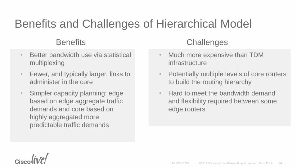
Benefits and Challenges of Hierarchical Model
• Better bandwidth use via statistical
multiplexing
• Fewer, and typically larger, links to
administer in the core
• Simpler capacity planning: edge
based on edge aggregate traffic
demands and core based on
highly aggregated more
predictable traffic demands
• Much more expensive than TDM
infrastructure
• Potentially multiple levels of core routers
to build the routing hierarchy
• Hard to meet the bandwidth demand
and flexibility required between some
edge routers
Benefits Challenges

Layer 3 Bypass Models
• Shifting the Capex budget out of (more expensive) IP equipment towards (lower cost) optical equipment
• Bypass options:
• At L2 (Lean Core): MPLS LSR
• At L1: OTN switching
• At L0: photonic bypass
• Partial vs full bypass (Hollow Core)
Layer 3
Layer 2
Layer 1
Layer 0 Bypass at L2Bypass at L1Bypass at L0

How to Use Layer 3 Bypass
• Hierarchical routing for small flows
• Lean core (bypass at L2) in hierarchical design
• OTN bypass (at L1) if a variety of flows going to different directions and intermediate flows
• DWDM bypass (at L0) for large flows
• Be cautious with full bypass

Integrated Multilayer Systems
Agnostic Fabric
MPLS IPOTN Ethernet
OS Virtualization / Hypervisor
SONET/SDH
DWDM
Linecard
VM
Control
Plane
VM
Admin
VM
NCS 4000

Multilayer Control Plane
• Peer Model: same domain, same topology
• Overlay Model: UNI, separate topologies; client can request circuit
setup and teardown
WDM (Server)
IP (Client)
Peer Model Overlay Model
UNI UNI

Cisco nLight Control Plane
• nLight extends GMPLS UNI with circuit attribute information exchange
• Circuit established per requirements
• SRLG’s to be excluded or included
• Path to follow another Circuit-ID
• Path to be disjoint from another Circuit-ID
• Optimization upon shortest latency
• Bound on latency not to exceed
• Optimization upon lowest optical cost
• Optical restoration
• Optical re-optimization
Client may requestServer may inform
• Circuit-ID
• SRLG’s along the circuit
• Path latency
• Information refresh
• Server topology/resource
• Server policy control

Bandwidth On Demand
WDM (Server)
IP (Client)
UNI-C
NNI
UNI-N NNI
UNI-C
UNI-N
1. Signals a circuit to egress UNI-C
2. Performs path calculation to find egress NNI and UNI-N
3. Signals the path
4. Performs impairment calculations
5. Sets up return path6. Informs UNI-C

Multilayer Protection and Restoration
• Multiple layers of routing options
• OTN/DWDM Protection: predesignated facility for fast switchover (< 50 ms)
• Router Link Fast Reroute: fast switchover (< 50 ms)
• OTN/DWDM Restoration: dynamic switchover for second level of service restoration (seconds to minutes)
• Layer 3 reroute

Multilayer Network Optimization
• Collection
• Topology
• Circuits
• Resources
• Analysis
• Impact Analysis
• What if Scenarios
• Restoration feasibility
• Optimization
• Coordinated Maintenance Feasibility
• Configuration
Packet'
OTN'
DWDM'
IP/MPLS'
GMPLS'
WSON'
Service' Service'
Packet'NE'
OTN'NE'
DWDM'NE'
NetworkCollec on/DeploymentPlug-Ins
NetworkOp miza on
Server

Multilayer Orchestration Architecture
Base Network Management Functions
Base Services Functions
SNMP OpenFlow NetconfHTTP/XML
Protocol Abstraction Layer
Device Access Functions
DB
Inventory ConfigTopology Fault Assurance SW MgmtPlatform
Network Elements
Application
North Bound APIs
Service Management Functions

Use Cases of Service Automation
• Network deployment automation
• Turn-up configuration
• Post-deployment connectivity verification
• Service provisioning automation
• Service optimization
• Bandwidth calendaring
• Operational automation
• DWDM power check
• Software image management and upgrade
• Network fault remediation
• Operational analytics

Challenges and Solutions
Agile DWDM layer
Multilayer control plane
Multilayer orchestration
Converged layers
Integrated systems
Flexible Layer 3 bypass
ODU grooming
Packet transport
100G and beyond
High channel count
Super channels
Multi-degree ROADMs
Risk Growth
Cost
Experience
Success
ProfitabilityReputation

The Provider Dollar Gap
Declining
Revenue
per bit
Exponential
Traffic Growth

Preserve What Is
Working
• Resiliency
• Scale
• Rich feature set
Achieve Business
Objectives
• Service agility and
velocity
• Simplified operations
• Higher value services
A Winning Strategy
Evolve for Emerging
Requirements
• Automation
• Convergence
• Virtualization
• Application interaction
+ =
Evolved Programmable Networks

Thank you


Participate in the “My Favorite Speaker” Contest
• Promote your favorite speaker through Twitter and you could win $200 of Cisco Press products (@CiscoPress)
• Send a tweet and include
• Your favorite speaker’s Twitter handle
• Two hashtags: #CLUS #MyFavoriteSpeaker
• You can submit an entry for more than one of your “favorite” speakers
• Don’t forget to follow @CiscoLive and @CiscoPress
• View the official rules at http://bit.ly/CLUSwin
Promote Your Favorite Speaker and You Could Be a Winner

Complete Your Online Session Evaluation
Don’t forget: Cisco Live sessions will be available for viewing on-demand after the event at CiscoLive.com/Online
• Give us your feedback to be entered into a Daily Survey Drawing. A daily winner will receive a $750 Amazon gift card.
• Complete your session surveys though the Cisco Live mobile app or your computer on Cisco Live Connect.

Continue Your Education
• Demos in the Cisco campus
• Walk-in Self-Paced Labs
• Table Topics
• Meet the Engineer 1:1 meetings
• Related sessions