arc welding supplies - 07 847 7870
TRANSCRIPT

PRECISION TIG 275
OPERATORʼS MANUAL
IM935April, 2007
Safety Depends on You
Lincoln arc welding and cuttingequipment is designed and builtwith safety in mind. However, youroverall safety can be increased byproper installation ... and thoughtfuloperation on your part. DO NOT
INSTALL, OPERATE OR REPAIR
THIS EQUIPMENT WITHOUT
READING THIS MANUAL AND
THE SAFETY PRECAUTIONS
CONTAINED THROUGHOUT.And, most importantly, think beforeyou act and be careful.
For use with machines having Code Numbers: 11160
• Sales and Service through Subsidiaries and Distributors Worldwide •
Cleveland, Ohio 44117-1199 U.S.A. TEL: 216.481.8100 FAX: 216.486.1751 WEB SITE: www.lincolnelectric.com
• World's Leader in Welding and Cutting Products •
Copyright © 2007 Lincoln Global Inc.
IP21S
N80
IEC 60974-1
ARC W
ELDIN
G SUPP
LIES
- 07 8
47 78
70

FOR ENGINEpowered equipment.
1.a. Turn the engine off before troubleshooting and maintenancework unless the maintenance work requires it to be running.
____________________________________________________1.b.Operate engines in open, well-ventilated
areas or vent the engine exhaust fumesoutdoors.
____________________________________________________1.c. Do not add the fuel near an open flame weld-
ing arc or when the engine is running. Stopthe engine and allow it to cool before refuel-ing to prevent spilled fuel from vaporizing oncontact with hot engine parts and igniting. Donot spill fuel when filling tank. If fuel is spilled,wipe it up and do not start engine until fumeshave been eliminated.
____________________________________________________1.d. Keep all equipment safety guards, covers and devices in posi-
tion and in good repair.Keep hands, hair, clothing and toolsaway from V-belts, gears, fans and all other moving partswhen starting, operating or repairing equipment.
____________________________________________________
1.e. In some cases it may be necessary to remove safetyguards to perform required maintenance. Removeguards only when necessary and replace them when themaintenance requiring their removal is complete.Always use the greatest care when working near movingparts.
___________________________________________________1.f. Do not put your hands near the engine fan.
Do not attempt to override the governor oridler by pushing on the throttle control rodswhile the engine is running.
___________________________________________________1.g. To prevent accidentally starting gasoline engines while
turning the engine or welding generator during maintenancework, disconnect the spark plug wires, distributor cap ormagneto wire as appropriate.
iSAFETYi
ARC WELDING CAN BE HAZARDOUS. PROTECT YOURSELF AND OTHERS FROM POSSIBLE SERIOUS INJURY OR DEATH.
KEEP CHILDREN AWAY. PACEMAKER WEARERS SHOULD CONSULT WITH THEIR DOCTOR BEFORE OPERATING.
Read and understand the following safety highlights. For additional safety information, it is strongly recommended that youpurchase a copy of “Safety in Welding & Cutting - ANSI Standard Z49.1” from the American Welding Society, P.O. Box 351040,Miami, Florida 33135 or CSA Standard W117.2-1974. A Free copy of “Arc Welding Safety” booklet E205 is available from theLincoln Electric Company, 22801 St. Clair Avenue, Cleveland, Ohio 44117-1199.
BE SURE THAT ALL INSTALLATION, OPERATION, MAINTENANCE AND REPAIR PROCEDURES ARE
PERFORMED ONLY BY QUALIFIED INDIVIDUALS.
WARNING
Mar ʻ95
ELECTRIC AND
MAGNETIC FIELDS
may be dangerous
2.a. Electric current flowing through any conductor causeslocalized Electric and Magnetic Fields (EMF). Weldingcurrent creates EMF fields around welding cables andwelding machines
2.b. EMF fields may interfere with some pacemakers, andwelders having a pacemaker should consult their physicianbefore welding.
2.c. Exposure to EMF fields in welding may have other healtheffects which are now not known.
2.d. All welders should use the following procedures in order tominimize exposure to EMF fields from the welding circuit:
2.d.1. Route the electrode and work cables together - Securethem with tape when possible.
2.d.2. Never coil the electrode lead around your body.
2.d.3. Do not place your body between the electrode andwork cables. If the electrode cable is on your rightside, the work cable should also be on your right side.
2.d.4. Connect the work cable to the workpiece as close aspossible to the area being welded.
2.d.5. Do not work next to welding power source.
1.h. To avoid scalding, do not remove theradiator pressure cap when the engine ishot.
For Diesel Engines: Diesel engine exhaust andsome of its constituents are known to the Stateof California to cause cancer, birth defects, andother reproductive harm.
For Gasoline Engines: The engine exhaust fromthis product contains chemicals known to theState of California to cause cancer, birth defects,or other reproductive harm.
CALIFORNIA PROPOSITION 65 WARNINGS
ARC W
ELDIN
G SUPP
LIES
- 07 8
47 78
70

iiSAFETYii
ARC RAYS can burn.4.a. Use a shield with the proper filter and cover
plates to protect your eyes from sparks andthe rays of the arc when welding or observingopen arc welding. Headshield and filter lensshould conform to ANSI Z87. I standards.
4.b. Use suitable clothing made from durable flame-resistantmaterial to protect your skin and that of your helpers fromthe arc rays.
4.c. Protect other nearby personnel with suitable, non-flammablescreening and/or warn them not to watch the arc nor exposethemselves to the arc rays or to hot spatter or metal.
ELECTRIC SHOCK can kill.3.a. The electrode and work (or ground) circuits
are electrically “hot” when the welder is on.Do not touch these “hot” parts with your bareskin or wet clothing. Wear dry, hole-freegloves to insulate hands.
3.b. Insulate yourself from work and ground using dry insulation.Make certain the insulation is large enough to cover your fullarea of physical contact with work and ground.
In addition to the normal safety precautions, if welding
must be performed under electrically hazardous
conditions (in damp locations or while wearing wet
clothing; on metal structures such as floors, gratings or
scaffolds; when in cramped positions such as sitting,
kneeling or lying, if there is a high risk of unavoidable or
accidental contact with the workpiece or ground) use
the following equipment:
• Semiautomatic DC Constant Voltage (Wire) Welder.
• DC Manual (Stick) Welder.
• AC Welder with Reduced Voltage Control.
3.c. In semiautomatic or automatic wire welding, the electrode,electrode reel, welding head, nozzle or semiautomaticwelding gun are also electrically “hot”.
3.d. Always be sure the work cable makes a good electricalconnection with the metal being welded. The connectionshould be as close as possible to the area being welded.
3.e. Ground the work or metal to be welded to a good electrical(earth) ground.
3.f. Maintain the electrode holder, work clamp, welding cable andwelding machine in good, safe operating condition. Replacedamaged insulation.
3.g. Never dip the electrode in water for cooling.
3.h. Never simultaneously touch electrically “hot” parts ofelectrode holders connected to two welders because voltagebetween the two can be the total of the open circuit voltageof both welders.
3.i. When working above floor level, use a safety belt to protectyourself from a fall should you get a shock.
3.j. Also see Items 6.c. and 8.
FUMES AND GASES
can be dangerous.5.a. Welding may produce fumes and gases
hazardous to health. Avoid breathing thesefumes and gases. When welding, keepyour head out of the fume. Use enoughventilation and/or exhaust at the arc to keep
fumes and gases away from the breathing zone. When
welding with electrodes which require special
ventilation such as stainless or hard facing (see
instructions on container or MSDS) or on lead or
cadmium plated steel and other metals or coatings
which produce highly toxic fumes, keep exposure as
low as possible and below Threshold Limit Values (TLV)
using local exhaust or mechanical ventilation. In
confined spaces or in some circumstances, outdoors, a
respirator may be required. Additional precautions are
also required when welding on galvanized steel.
5. b. The operation of welding fume control equipment is affectedby various factors including proper use and positioning of theequipment, maintenance of the equipment and the specificwelding procedure and application involved. Worker expo-sure level should be checked upon installation and periodi-cally thereafter to be certain it is within applicable OSHA PELand ACGIH TLV limits.
5.c. Do not weld in locations near chlorinated hydrocarbon vaporscoming from degreasing, cleaning or spraying operations.The heat and rays of the arc can react with solvent vapors toform phosgene, a highly toxic gas, and other irritating prod-ucts.
5.d. Shielding gases used for arc welding can displace air andcause injury or death. Always use enough ventilation,especially in confined areas, to insure breathing air is safe.
5.e. Read and understand the manufacturerʼs instructions for thisequipment and the consumables to be used, including thematerial safety data sheet (MSDS) and follow youremployerʼs safety practices. MSDS forms are available fromyour welding distributor or from the manufacturer.
5.f. Also see item 1.b.
AUG 06
ARC W
ELDIN
G SUPP
LIES
- 07 8
47 78
70

FOR ELECTRICALLYpowered equipment.
8.a. Turn off input power using the disconnectswitch at the fuse box before working onthe equipment.
8.b. Install equipment in accordance with the U.S. NationalElectrical Code, all local codes and the manufacturerʼsrecommendations.
8.c. Ground the equipment in accordance with the U.S. NationalElectrical Code and the manufacturerʼs recommendations.
CYLINDER may explode
if damaged.7.a. Use only compressed gas cylinders
containing the correct shielding gas for theprocess used and properly operatingregulators designed for the gas and
pressure used. All hoses, fittings, etc. should be suitable forthe application and maintained in good condition.
7.b. Always keep cylinders in an upright position securelychained to an undercarriage or fixed support.
7.c. Cylinders should be located:• Away from areas where they may be struck or subjected tophysical damage.
• A safe distance from arc welding or cutting operations andany other source of heat, sparks, or flame.
7.d. Never allow the electrode, electrode holder or any otherelectrically “hot” parts to touch a cylinder.
7.e. Keep your head and face away from the cylinder valve outletwhen opening the cylinder valve.
7.f. Valve protection caps should always be in place and handtight except when the cylinder is in use or connected foruse.
7.g. Read and follow the instructions on compressed gascylinders, associated equipment, and CGA publication P-l,“Precautions for Safe Handling of Compressed Gases inCylinders,” available from the Compressed Gas Association1235 Jefferson Davis Highway, Arlington, VA 22202.
iiiSAFETYiii
Jan 07
WELDING SPARKS cancause fire or explosion.6.a. Remove fire hazards from the welding area.
If this is not possible, cover them to preventthe welding sparks from starting a fire.Remember that welding sparks and hot
materials from welding can easily go through small cracksand openings to adjacent areas. Avoid welding nearhydraulic lines. Have a fire extinguisher readily available.
6.b. Where compressed gases are to be used at the job site,special precautions should be used to prevent hazardoussituations. Refer to “Safety in Welding and Cutting” (ANSIStandard Z49.1) and the operating information for theequipment being used.
6.c. When not welding, make certain no part of the electrodecircuit is touching the work or ground. Accidental contact cancause overheating and create a fire hazard.
6.d. Do not heat, cut or weld tanks, drums or containers until theproper steps have been taken to insure that such procedureswill not cause flammable or toxic vapors from substancesinside. They can cause an explosion even though they havebeen “cleaned”. For information, purchase “RecommendedSafe Practices for the Preparation for Welding and Cutting ofContainers and Piping That Have Held HazardousSubstances”, AWS F4.1 from the American Welding Society(see address above).
6.e. Vent hollow castings or containers before heating, cutting orwelding. They may explode.
6.f. Sparks and spatter are thrown from the welding arc. Wear oilfree protective garments such as leather gloves, heavy shirt,cuffless trousers, high shoes and a cap over your hair. Wearear plugs when welding out of position or in confined places.Always wear safety glasses with side shields when in awelding area.
6.g. Connect the work cable to the work as close to the weldingarea as practical. Work cables connected to the buildingframework or other locations away from the welding areaincrease the possibility of the welding current passingthrough lifting chains, crane cables or other alternate circuits.This can create fire hazards or overheat lifting chains orcables until they fail.
6.h. Also see item 1.c.
6.I. Read and folllow NFPA 51B “ Standard for Fire PreventionDuring Welding, Cutting and Other Hot Work”, available fromNFPA, 1 Batterymarch Park,PO box 9101, Quincy, Ma022690-9101.
6.j. Do not use a welding power source for pipe thawing.
ARC W
ELDIN
G SUPP
LIES
- 07 8
47 78
70

ivSAFETYiv
ARC W
ELDIN
G SUPP
LIES
- 07 8
47 78
70

vv
Thank You for selecting a QUALITY product by Lincoln Electric. We want youto take pride in operating this Lincoln Electric Company product •••as much pride as we have in bringing this product to you!
Read this Operators Manual completely before attempting to use this equipment. Save this manual and keep ithandy for quick reference. Pay particular attention to the safety instructions we have provided for your protection.The level of seriousness to be applied to each is explained below:
WARNING
This statement appears where the information must be followed exactly to avoid serious personal injury or loss of life.
This statement appears where the information must be followed to avoid minor personal injury or damage to this equipment.
CAUTION
Please Examine Carton and Equipment For Damage ImmediatelyWhen this equipment is shipped, title passes to the purchaser upon receipt by the carrier. Consequently, Claimsfor material damaged in shipment must be made by the purchaser against the transportation company at the timethe shipment is received.
Please record your equipment identification information below for future reference. This information can be foundon your machine nameplate.
Product _________________________________________________________________________________
Model Number ___________________________________________________________________________
Code Number or Date Code_________________________________________________________________
Serial Number____________________________________________________________________________
Date Purchased___________________________________________________________________________
Where Purchased_________________________________________________________________________
Whenever you request replacement parts or information on this equipment, always supply the information youhave recorded above. The code number is especially important when identifying the correct replacement parts.
On-Line Product Registration- Register your machine with Lincoln Electric either via fax or over the Internet.
• For faxing: Complete the form on the back of the warranty statement included in the literature packetaccompanying this machine and fax the form per the instructions printed on it.
• For On-Line Registration: Go to our WEB SITE at www.lincolnelectric.com. Choose “Quick Links” and then“Product Registration”. Please complete the form and submit your registration.
CUSTOMER ASSISTANCE POLICY
The business of The Lincoln Electric Company is manufacturing and selling high quality welding equipment, consumables, and cutting equip-ment. Our challenge is to meet the needs of our customers and to exceed their expectations. On occasion, purchasers may ask Lincoln Electricfor advice or information about their use of our products. We respond to our customers based on the best information in our possession at thattime. Lincoln Electric is not in a position to warrant or guarantee such advice, and assumes no liability, with respect to such information oradvice. We expressly disclaim any warranty of any kind, including any warranty of fitness for any customerʼs particular purpose, with respectto such information or advice. As a matter of practical consideration, we also cannot assume any responsibility for updating or correcting anysuch information or advice once it has been given, nor does the provision of information or advice create, expand or alter any warranty withrespect to the sale of our products.
Lincoln Electric is a responsive manufacturer, but the selection and use of specific products sold by Lincoln Electric is solely within the controlof, and remains the sole responsibility of the customer. Many variables beyond the control of Lincoln Electric affect the results obtained inapplying these types of fabrication methods and service requirements.
Subject to Change – This information is accurate to the best of our knowledge at the time of printing. Please refer to www.lincolnelectric.comfor any updated information.
ARC W
ELDIN
G SUPP
LIES
- 07 8
47 78
70

TABLE OF CONTENTSPage.
Installation ..........................................................................................................Section ATechnical Specifications........................................................................................A-1, A-2Safety Precautions.. ............................................................................................................................................... .A-3
Select Suitable Location........................................................................................A-3Grinding .................................................................................................................A-3Stacking.................................................................................................................A-3Undercarriage Lifting and Moving .........................................................................A-3Tilting .....................................................................................................................A-3Environmental Rating ............................................................................................A-3
Machine Grounding and High Frequency Interference Protection .......................A-3, A-4Input and Grounding Connections ..............................................................................A-4Output Cable, Connections and Limitations ................................................................A-5
Work Cable Connection ..................................................................................A-5Stick Electrode Cable Connection ..................................................................A-5TIG Torch Connection .....................................................................................A-6Auxiliary Power Connections ..........................................................................A-7Remote Control (If Used) ................................................................................A-7Robotic Interface Connection ..................................................................A-7, A-8
________________________________________________________________________OPERATION..........................................................................................................................................................Section B-1
Safety Precautions.......................................................................................................B-1Product Description......................................................................................................B-1
Pipe Thawing.........................................................................................................B-1 Duty Cycle: ............................................................................................................B-1Recommended Processes and Equipment ...........................................................B-2Controls and Settings...........................................................................B-3 THRU B-6Internal Set Up Controls ........................................................................................B-7Stick Welding Features..........................................................................................B-7TIG Welding Features ...........................................................................................B-7
2 Step Trigger Modes......................................................................................B-84 Step Trigger Modes ....................................................................................B-9
TIG Welding Cycle Chart ....................................................................................B-10Setup Guidelines for TIG Welding with an Amptrol .....................................B-10, B11Making a TIG Weld with an Amptrol ....................................................................B-12
________________________________________________________________________Accessories ............................................................................................................................................... .......Section C
Optional Equipment .....................................................................................................C-1________________________________________________________________________Maintenance ......................................................................................................................................................Section D
Safety Precautions.......................................................................................................D-1Routine and Periodic Maintenance..............................................................................D-1Overload Protection .....................................................................................................D-1Service Procedures, Component Access,Spark Gap Adjustment ...............................D-2Under-Cooler Service ..................................................................................................D-2Meter Calibration Adjustment.......................................................................................D-3
________________________________________________________________________Troubleshooting .............................................................................................................................................Section E
Safety Precautions.......................................................................................................E-1How To Use TroubleShooting Guide............................................................................E-1Troubleshooting .................................................................................................E-2 to E-7
________________________________________________________________________Diagrams ..............................................................................................................................................................Section F
Wiring Diagrams.........................................................................................................................................................F-1Dimension Prints........................................................................................................................................................F-2
________________________________________________________________________Parts List......................................................................................................................................................................P-543
vivi
ARC W
ELDIN
G SUPP
LIES
- 07 8
47 78
70

A-1INSTALLATION
PRECISION TIG 275
A-1
TECHNICAL SPECIFICATIONS-PRECISION TIG 275 (K2620-1 Export-50/60Hz)
Voltage + 10%
220-230/380-400/415
Max. Amps With Out
Power Factor Capacitor
95/55/50109/63/58
80/46/4285/49/45
70/41/3765/38/3510/6/5400W
Max. Amps With
Power Factor Capacitor
80/46/4386/50/46
64/37/3467/39/36
52/30/2846/27/2523/13/12
500W
Duty Cycle-Applications
40%AC/DC Stick / Balance TIG
Unbalance (70% Penetration#) AC TIG60%
AC/DC Stick / Balance TIGUnbalance (70% Penetration#) AC TIG
100%AC/DC Stick / Balance TIG
Unbalance (70% Penetration#) AC TIGIdle AmpsIdle Power
RATED INPUT - SINGLE PHASE ONLY
#Exceeds NEMA Unbalanced Load Specification comparable for Auto-Balance.
* 50/60HZ IEC Max. range exceeds 310A.
RATED POWER FACTOR (STICK) .65 min. .77 min.
RATED OUTPUT - IEC 60974-1
Duty Cycle-Applications
40%AC/DC Stick / Balance TIG
Unbalance (70% Penetration#) AC TIG60%
AC/DC Stick / Balance TIGUnbalance (70% Penetration#) AC TIG
100%AC/DC Stick / Balance TIG
Unbalance (70% Penetration#) AC TIG
Volts at Rated Amperes
31.0 20.2
29.0 18.0
28.016.0
Amps
275255
225200
200150
ADDITIONAL OUTPUT CAPACITYOutput Current
Range
2Amps DCto
340Amps AC-DC*
Type of Output
CC (Constant Current)AC/DC (GTAW)Stick (SMAW)
Maximum Open
Circuit Voltage
(STICK AND TIG)AC/DC OCV: 75/68
Auxiliary Power
5 Amp Circuit Breakerand grounded 220VAC
Euro(Schuko) receptacle
ARC W
ELDIN
G SUPP
LIES
- 07 8
47 78
70

A-2INSTALLATION
PRECISION TIG 275
A-2
Height Width Depth Weight
31.0 in. 22.0 in. 26.0 in. Approx. 397 lbs.787 mm 559 mm 660 mm 180 kgs.
PHYSICAL DIMENSIONS
1 ALSO CALLED ʻINVERSE TIME" OR "THERMAL/MAGNETIC " CIRCUIT BREAKERS; CIRCUIT BREAKERS WHICH HAVE A DELAY IN TRIPPING ACTION THAT DECREASES ASTHE MAGNITUDE OF CURRENT INCREASES.
TEMPERATURE RANGES
OPERATING TEMPERATURE RANGE
-20°C to +40°C (-04° to +104°F)
TRANSFORMER INSULATION CLASS 180°C (H)
STORAGE TEMPERATURE RANGE
-40°C to +85°C (-40° to +185°F)
For all Stick, DC TIG, and Balanced AC TIG Welding
at 275A/40% Duty Cycle with out Standard Power
Factor Correction Capacitors
Based on the 1999 U.S. National Electrical Code
For Unbalanced AC TIG Welding Above 275 Amps:
255A/40% Duty Cycle, Auto-Balance Penetration with
out Standard Power Factor Correction Capacitors
Based on the 1999 U.S. National Electrical Code
RECOMMENDED INPUT WIRE AND FUSE SIZES
Input
Voltage /
phase/
Frequency
220-230/1/50/60
380-400/1/50/60
415/1/50/60
Input
Ampere
Rating
Rating on
Nameplate
95
55
50
Input
Ampere
Rating
109
63
58
Type 75°C
Copper
Ground Wire in
Conduit AWG
(IEC) Sizes
6 (13.3 mm2)
8 (8.4mm2)
8 (8.4mm2)
Type 75°C
Copper
Ground Wire in
Conduit AWG
(IEC) Sizes
6 (13.3 mm2)
8 (8.4 mm2)
8 (8.4 mm2)
Fuse
(Super Lag)
or Breaker
Size1
125
80
80
Fuse
(Super Lag)
or Breaker
Size1
150
90
90
Type 75°C
Copper Wire in
Conduit AWG
(IEC) Sizes
40°C (104°F)
Ambient
4 (21.2 mm2)
8 (8.4mm2)
8 (8.4mm2)
Type 75°C
Copper Wire in
Conduit AWG
(IEC) Sizes
40°C (104°F)
Ambient
4 (21.2 mm2)
6 (13.3 mm2)
6 (13.3 mm2)
ARC W
ELDIN
G SUPP
LIES
- 07 8
47 78
70

A-3INSTALLATION
PRECISION TIG 275
A-3
SAFETY PRECAUTIONS
SELECT SUITABLE LOCATION
Place the welder where clean cooling air can freely cir-culate in through the top rear vents and out through thebottom rear vents. Dirt, dust or any foreign materialthat can be drawn into the welder should be kept at aminimum. Failure to observe these precautions canresult in excessive operating temperatures and nui-sance trips.
GRINDING
Do not direct grinding particles towards the welder. Anabundance of conductive material can cause mainte-nance problems.
STACKINGThe Precision TIG 275's cannot be stacked .
UNDERCARRIAGE LIFTING AND MOVING
When the Precision TIG 275 is purchased as a weld-ing package, or used with any of the availableUndercarriage optional accessories, proper installationmakes the Precision TIG 275 lift bale nonfunctional.Do not attempt to lift the power source with an under-carriage attached. The undercarriage is designed forhand moving only; mechanized movement can lead topersonal injury and/or damage to the Precision TIG275.
TILTINGEach machine must be placed on a secure, level sur-face, either directly or on a recommended undercar-riage. The machine may topple over if this precautionis not followed.
ENVIRONMENTAL RATING
Precision TIG 275 power sources carry an IP21SEnvironmental rating. They are rated for use in damp,dirty rain-sheltered environments.
MACHINE GROUNDING AND HIGH FRE-
QUENCY INTERFERENCE PROTECTION
The frame of the welder must be grounded. A ground screwmarked with the symbol is located on the input connectionpanel (Figure A.1) for this purpose. See your local and nation-al electrical codes for proper grounding methods.
The spark gap oscillator in the high frequency genera-tor, being similar to a radio transmitter, can be blamedfor many radio, TV and electronic equipment interfer-ence problems. These problems may be the result ofradiated interference. Proper grounding methods canreduce or eliminate radiated interference.
The Precision TIG 275 has been field tested under rec-ommended installation conditions and has been foundto comply with F.C.C. allowable radiation limits. Thiswelder has also been found to comply with NEMA stan-dards for high frequency stabilized power sources.
Radiated interference can develop in the following fourways:
• Direct interference radiated from the welder.• Direct interference radiated from the welding leads.• Direct interference radiated from feedback into the
power lines.• Interference from re-radiation of "pickup" by
ungrounded metallic objects.
Keeping these contributing factors in mind, installingthe equipment per the following instructions shouldminimize problems:
1. Keep the welder power supply lines as short aspossible. Input leads within 50 feet (15.2 m) of thewelder should be enclosed in rigid metallic conduitor equivalent shielding. There must be good electri-cal contact between this conduit and the welder.Both ends of the conduit must be connected to adriven ground and the entire length must be contin-uous.
2. Keep the work and electrode leads as short as pos-sible and as close together as possible. Lengthsshould not exceed 25 feet (7.6 m). Tape the leadstogether when practical.
Read entire installation section before starting
installation.
ELECTRIC SHOCK can kill.• Only qualified personnel should
perform this installation.
• Turn the input power OFF at the
disconnect switch or fuse box
before working on this
equipment.
• Do not touch electrically hot
parts.
• Always connect the Precision TIG 275 grounding screw (behind
the reconnect panel cover located near the back of the left case
side) to a good electrical earth ground.
• Always connect the Precision TIG 275 to a power supply
grounded in accordance with the National Electrical Code and
all local codes.
WARNING
ARC W
ELDIN
G SUPP
LIES
- 07 8
47 78
70
INPUT and GROUNDING CONNECTIONS
Be sure the voltage, phase, and frequency of the inputpower is as specified on the rating plate, located on therear of the machine.
Fuse the input circuit with the recommended super lagfuses or delay type1 circuit breakers. Choose an inputand grounding wire size according to local or nationalcodes or use Section A-2. Using fuses or circuit break-ers smaller than recommended may result in "nui-sance" tripping from welder inrush currents even if notwelding at high currents.
Unbalanced AC TIG welding draws higher input cur-rents than those for Stick, DC TIG, or Balanced AC TIGwelding. The welder is designed for these higher inputcurrents. However, where unbalanced AC TIG weldingabove 185 amps is planned, the higher input currentsrequire larger input wire sizes and fuses per Section A-2:
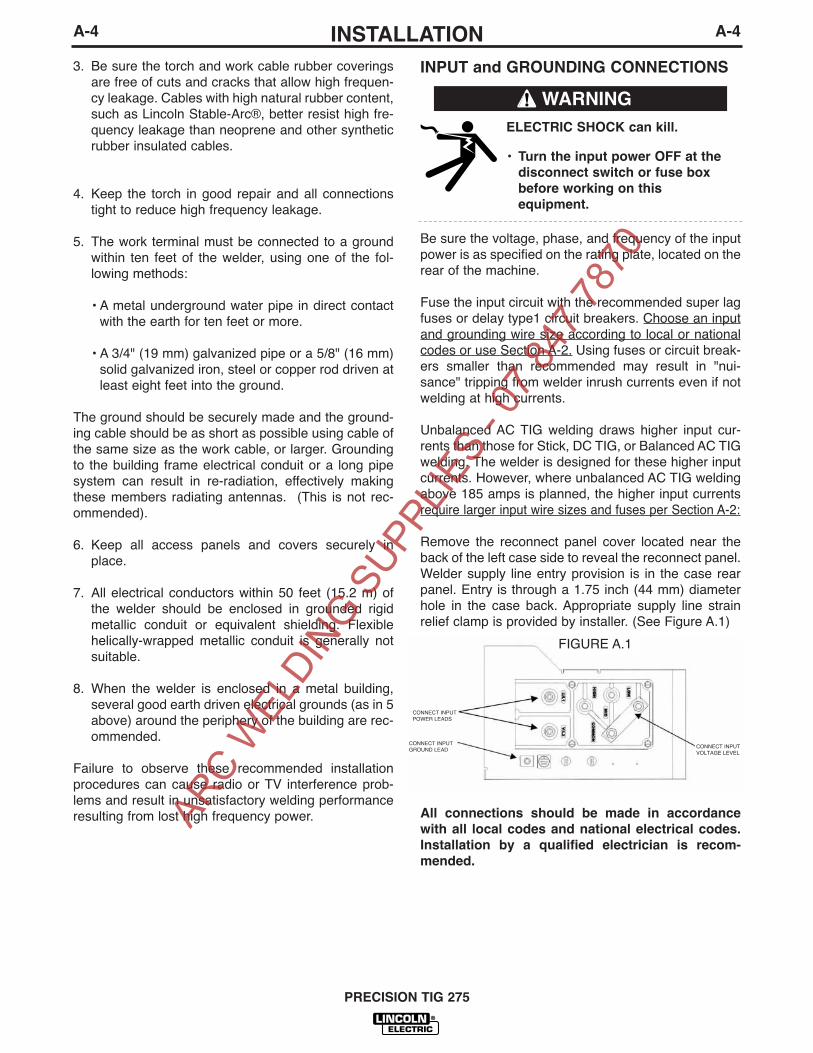
Remove the reconnect panel cover located near theback of the left case side to reveal the reconnect panel.Welder supply line entry provision is in the case rearpanel. Entry is through a 1.75 inch (44 mm) diameterhole in the case back. Appropriate supply line strainrelief clamp is provided by installer. (See Figure A.1)
All connections should be made in accordance
with all local codes and national electrical codes.
Installation by a qualified electrician is recom-
mended.
A-4INSTALLATION
PRECISION TIG 275
A-4
3. Be sure the torch and work cable rubber coveringsare free of cuts and cracks that allow high frequen-cy leakage. Cables with high natural rubber content,such as Lincoln Stable-Arc®, better resist high fre-quency leakage than neoprene and other syntheticrubber insulated cables.
4. Keep the torch in good repair and all connectionstight to reduce high frequency leakage.
5. The work terminal must be connected to a groundwithin ten feet of the welder, using one of the fol-lowing methods:
• A metal underground water pipe in direct contactwith the earth for ten feet or more.
• A 3/4" (19 mm) galvanized pipe or a 5/8" (16 mm)solid galvanized iron, steel or copper rod driven atleast eight feet into the ground.
The ground should be securely made and the ground-ing cable should be as short as possible using cable ofthe same size as the work cable, or larger. Groundingto the building frame electrical conduit or a long pipesystem can result in re-radiation, effectively makingthese members radiating antennas. (This is not rec-ommended).
6. Keep all access panels and covers securely inplace.
7. All electrical conductors within 50 feet (15.2 m) ofthe welder should be enclosed in grounded rigidmetallic conduit or equivalent shielding. Flexiblehelically-wrapped metallic conduit is generally notsuitable.
8. When the welder is enclosed in a metal building,several good earth driven electrical grounds (as in 5above) around the periphery of the building are rec-ommended.
Failure to observe these recommended installationprocedures can cause radio or TV interference prob-lems and result in unsatisfactory welding performanceresulting from lost high frequency power.
WARNING
ELECTRIC SHOCK can kill.
• Turn the input power OFF at the
disconnect switch or fuse box
before working on this
equipment.
FIGURE A.1
CONNECT INPUTPOWER LEADS
CONNECT INPUTVOLTAGE LEVEL
CONNECT INPUTGROUND LEAD
ARC W
ELDIN
G SUPP
LIES
- 07 8
47 78
70

A-5INSTALLATION
PRECISION TIG 275
A-5
Recommended Cable Sizes for Combined Lengths ofCopper Work and Electrode Cables using 75o C Wire:
Machine Rating 0 to 100 Ft. 101 to 200 Ft 201 to 250 Ft
275A/40% #1 (42.4 mm2) 1/0 (53.5 mm2) 2/0 (67.4 mm2)
WORK CABLE CONNECTION
A 15ʼ (2/0) weld cable with clamp is available (K2150-1),Otherwise, it is user provided.
With power source off, connect a separate work cableto the 1/2-13 threaded "WORK" stud of the welder, andsecure a tight connection with the flange nut provided.The work cable should be routed through the cablestrain relief hole provided in the base directly below thewelding output terminal.Note: If the Precision TIG is equipped with an Under-Cooler or Under-Storage unit, the coiled work cableand clamp, or excess work cable length, may be con-veniently stored in the drawer while remaining con-nected.
STICK ELECTRODE CABLE CONNECTION
If manual stick welding is desired, with power sourceoff, connect a stick electrode cable to the 1/2-13threaded "STICK Electrode" stud of the welder, andsecure a tight connection with the flange nut provided.The electrode cable should be routed through thecable strain relief hole provided in the base directlybelow the welding output terminal.
DISCONNECT STICK ELECTRODE WELDING
CABLE WHEN TIG WELDING.
EVEN THOUGH HI-FREQ IS NOT APPLIED TO THE
PRECISION TIG STICK TERMINAL, IT WILL BE
ELECTRICALLY "HOT" TO WORK WHEN TIG
WELDING.
------------------------------------------------------------------------
1. Connect the terminal marked (below the recon-nect panel) to an earth ground.
2. Connect the input leads to terminals marked L1 (U)and L2 (V) on the reconnect panel. Use a singlephase line or one phase of a two or three phase line.
3. On multiple input voltage welders, be sure thereconnect panel is connected for the voltage beingsupplied to the welder.
Failure to follow these instructions can cause
immediate failure of components within the welder.
------------------------------------------------------------------------
Welders are shipped connected for the highest inputvoltage as listed on the rating plate. To change thisconnection, designations on the reconnect panel LOW,MID, and HIGH correspond to the name plated inputvoltages of a triple voltage welder. Dual voltagewelders use only LOW and HIGH.
EXAMPLE: This model has a voltage range for LOW
and MID connections: LOW is 220-230V, MID is 380-400V and High is 415V.
Reconnect the jumper strap to the terminal stud corre-sponding to the input voltage level used. Make sure allconnections are tight.
OUTPUT CABLES, CONNECTIONS AND
LIMITATIONS
• To avoid being startled by a high frequency
shock, keep the TIG torch and cables in good
condition
• Turn the power switch of the power source OFF
before installing adapters on cable or when con-
necting or disconnecting adapter plugs to power
source.
-----------------------------------------------------------------------
Refer to Figure A.2 for the location of the WORK andSTICK terminals, as well as the TIG Torch connectionpanel.
WARNING
WARNING
CAUTION
ARC W
ELDIN
G SUPP
LIES
- 07 8
47 78
70

A-6INSTALLATION
PRECISION TIG 275
A-6
TIG TORCH CONNECTION
The Precision TIG torch connection box, located on theright side of the machine, provides all the input andoutput connections for the installation of both air-cooled and water-cooled TIG torches with fittings con-forming to Compressed Gas Association (CGA) stan-dards:Note: The Precision TIG provides an insulated TorchReel and Holster for handy and safe storage of con-nected torch when not welding, and excess torch cablelength while welding.
Combination connectors (Power/Water and
Power/Gas) are electrically "hot" while welding in
STICK or TIG modes.
If using an Air-Cooled Torch be sure coolant is
shut off and/or Cooler is unplugged from the
Precision TIG Water Cooler Receptacle on the
torch side of the upper case back.
Observe the safety precautions necessary for han-
dling and using compressed gas containers.
Contact your supplier for specifics.
CYLINDER could explode
if damaged.
• Keep cylinder upright and
chained to a support.
• Keep cylinder away from areas
where it could be damaged.
• Never allow the torch to touch the cylinder.
• Keep cylinder away from live electrical cir-
cuits.
• Maximum inlet pressure 150 psi.
-----------------------------------------------------------------The Precision TIG machines do not have Hi-Freq.available at the Stick electrode stud, therefore studconnection adapters (such as LECO. S19257-series)cannot be used for torch connection.
Single-piece cable air-cooled torches with a 3/8-24 RHconnector fitting (such as the Magnum PTA-9/-17, or LA-9/-17) require the provided S20403-4 Torch Connector,while those with a 7/8-14 RH connector fitting (such asthe Magnum PTA-26, or LA-26) require the availableK2166-1 Torch Connector. (See Figure A.3)
Two-piece cable air-cooled torches (such as PTA-, or LA-torches) can be used with the available 1/2” StudConnector (S20403-3) with with a 7/8-14 LH male fitting.
Magnum PTW-18/-20 (or LW-) water-cooled Torchesrequire no adapter for Precision TIG connection.
WARNING
WORKSTICK WORKSTICK
STICKELE CTRODE
STUD
WORK
STUD
TIG TORCHCONNECTION
PANEL
FIGURE A(Shown without hinged stud cover)
REM OTE
CONTROLRECEPTACLE
CABLESTRAIN
REL IEF HOLE S
FIGURE A.2
ARC W
ELDIN
G SUPP
LIES
- 07 8
47 78
70

A-7INSTALLATION
PRECISION TIG 275
A-7
AUXILIARY POWER CONNECTIONS
The Precision TIG machines provide a standard NEMA5-15R duplex receptacle, located on the upper caseback on the torch side of the machine:
• The bottom outlet of this duplex receptacle providesswitched 115VAC power for the Under-Cooler, orWater Solenoid accessory. This Cooler receptacleturns on when the arc starts and remains on for about8 minutes after the arc goes out (with the Fan-As-Needed machine cooling fan, see MaintenanceSection), so the Coolerʼs fan and water pump will notrun continuously in idle, but will run while welding.
• The top outlet of this duplex receptacle provides atleast 8 amps at 115VAC, whenever the Precision TIGPower switch is ON. This auxiliary circuit is intendedfor running 115VAC accessories or small power tools.Note: Some types of equipment, especially pumpsand large motors, have starting currents which aresignificantly higher than their running current. Thesehigher starting currents may cause the circuit breakerto open. (See next paragraph)
• Both the receptacle circuits are protected from shortsand overloads by a 15 amp circuit breaker, locatedabove the receptacle. If the breaker trips, its buttonpops out exposing a red ring. When the circuit break-er cools, the button can be reset by pressing it backin.
Note: When the breaker trips, not only will the auxil-iary and cooler power be interrupted, but so will thepower to the shielding gas solenoid and machinecooling fan.
The Precision TIG Export models also provide agrounded 220vac Euro type Schuko receptacle and a5 amp circuit breaker, located on the upper case backon the reconnect side of the machine, intended for usewith a 220vac water cooler.
REMOTE CONTROL (If Used)
The Foot Amptrol or other Remote accessory, isinstalled by routing the plug of its control cable upthrough the left cable strain relief hole provided in thebase (see Figure A.2), then connecting the 6-pin plugto the mating Remote receptacle behind the stud panelcover. (See Operation Section B-2 for mating plugwiring.)
Note: If the Precision TIG is equipped with an Under-Cooler or Under-Storage unit, the Foot Pedal (or otherremote control accessory) and coiled control cable, orexcess cable length, may be conveniently stored in thedrawer while remaining connected.
FIGURE A.3
For Gas Supply hosewith 5/8-18RH male
For Coolant SupplyHoseswith 5/8-18LH male(Provided with Under-Cooler Cart)
ARC W
ELDIN
G SUPP
LIES
- 07 8
47 78
70

A-8INSTALLATION
PRECISION TIG 275
A-8
ROBOTIC INTERFACE CONNECTION
Robotic interface can be made at the RemoteReceptacle (See Operation Section B-2). The machineis shipped with the remote receptacle circuit internallyconnected to receptacle J5 of the Control board forstandard Amptrol operation. In order to enable theremote receptacle for robotic interface its connectionplug must be moved from J5 to J5A on the Controlboard. (Refer to the machine Wiring Diagram.)
The robotic interface functions with the Precision TIGset to either TIG or STICK mode, but must be inREMOTE switch position for the Preset Control inter-face to function. When in the REMOTE position withrobotic interface neither the MAXIMUM OUTPUT northe MINIMUM OUTPUT panel controls limit the inter-face control setting over the rated output range of themachine.
The diagram in Figure A.4 below shows the remotereceptacle plug connections and signals for roboticinterface:
In addition; a Peak Pulse output signal is provided atJ21 receptacle on the Advanced Control PCB. Thisoutput provides a 0.2A rated switch circuit between pin1 (+) and pin 2 (com) for an external 40VDC suppliedrelay (with coil diode). This switch closes when thePeak Pulse is on, and opens when off.
FIGURE A.4
ARC W
ELDIN
G SUPP
LIES
- 07 8
47 78
70

B-1OPERATIONB-1
PRODUCT DESCRIPTION
The Precision TIG 275 is part of a family of industrialarc welding power sources providing constant current,single range square wave AC/DC TIG (GTAW) withpatented Micro-StartTM II Technology, Presettable Min.and Max. Output controls, and built-in high frequencystabilization for continuous AC TIG and DC TIG start-ing. It also has AC/DC Stick (SMAW) capability, withadjustable Arc Force availability. A TIG Pulse Panel,Power Factor Capacitors and a Water Solenoid areavailable as field installed optional kits. Also, a newUndercarriage (with double gas bottle rack) is availablefor field installation, as well as a new Under-CoolerCart, which is also included in an available efficientlyintegrated entire TIG Welding Package with conve-nient built-in storage provisions for welding equipmentand components.
The Precision TIG 275 includes advanced featuressuch as: Digital Meter, Presettable control, AutoBalanceTM, Fan As Needed (F.A.N.) fixed Preflow, vari-able Postflow shielding gas and Timers. In addition, 2-Step/4-Step and Pulse TIG operation with adjustableDownslope Time control are included with an availablefield installed kit. It also features a Stick stud panel anda universal TIG torch connection box for simultaneous,but separated, electrode outputs.
The Precision TIG 275 has enhanced Features whichincludes the following:
• MicroStart™ II • Auto-Balance optimized • Menu button added• Spot On selection added
PIPE THAWING
The Precision TIG 275 is not recommended for pipethawing.
Duty Cycle
The duty cycle is based upon a 10-minute time period;i.e., for 40% duty cycle, it is 4 minutes welding and 6minutes idling. If the rated duty cycle is significantlyexceeded, the thermostatic protection will shut off theoutput until the machine cools to a normal operatingtemperature. (Refer to Specification Section A-1)
PRECISION TIG 275
ELECTRIC SHOCK can kill.
• Only qualified personnel should
perform this installation.• Turn the input power OFF at the
disconnect switch or fuse box.
• Do not touch electrically live parts
or electrode with skin or wet cloth-
ing.
• Insulate yourself from work and
ground.
• Always wear dry insulating gloves.
• Read and follow “Electric Shock
Warnings” in the Safety section if weld-
ing must be performed under electrical-
ly hazardous conditions such as weld-
ing in wet areas or on or in the work-
piece.
FUMES AND GASES
can be dangerous.
• Keep your head out of fumes.
• Use ventilation or exhaust to
remove fumes from breathing
zone.
WELDING SPARKS
can cause fire or
explosion
• Keep flammable material away.
• Do not weld on containers that
have held combustibles.
ARC RAYS
can burn.
• Wear eye, ear and body
protection.
SAFETY PRECAUTIONS
Read and understand this entire section before operat-ing the machine.
Observe additional Safety Guidelines detailed in
the beginning of this manual.
WARNING
ARC W
ELDIN
G SUPP
LIES
- 07 8
47 78
70

B-2OPERATIONB-2
RECOMMENDED PROCESSES AND
EQUIPMENT
RECOMMENDED PROCESSES
The Precision TIG 275 is recommended for the TIG(GTAW) and Stick (SMAW) welding processes withinits output capacity range of 2 amps DC, or 5 amps AC,to 340 amps AC/DC. It is compatible with mostMagnum TIG accessories (refer EquipmentLimitations), as well as many industry standard items,such as TIG torches, hoses, and water coolers.
PROCESS LIMITATIONS
Precision TIG machines are not recommended for arcgouging due to it's limited output capacity, and are alsonot recommended for pipe thawing.
EQUIPMENT LIMITATIONS
The Precision TIG machines are protected from over-loads beyond the electrical ratings and duty cycles, perthe Specifications Section A-1, A-2, with Thermostatprotection of the primary and secondary transformercoils.
The Precision TIG machines do not have Hi-Frequencyavailable at the Stick electrode stud, therefore studconnection adapters (such as LECO. S19257-series)cannot be used for torch connection.
PRECISION TIG 275
RECOMMENDED EQUIPMENT/INTERFACE
TIG (air cooled)Machine: PT275Input Cable/Clamp: User providedGas Reg./Hose: LE/Harris 3100211Magnum Torch: PTA9 or PTA17Magnum Parts: KP507 or KP508 Work Clamp/Lead: K2150-1 Work Lead AssemblyFoot Amptrol: K870
ARC W
ELDIN
G SUPP
LIES
- 07 8
47 78
70

B-3OPERATIONB-3
1. POWER SWITCH - Input line switch turns inputpower ON or OFF, as indicated by the on or off sta-tus of the front panel displays.
2. POLARITY SWITCH – The 3-position rotary powerswitch has detente positions for DC-, AC and DC+selections for the Electrode output welding polarity.
3. MODE SWITCH – The mode switch allows vertical-ly positioned selection of the two machine weldingmodes. The selected mode is indicated by a lit col-ored panel light which permits viewing the machinesetting from a distance:3.a STICK mode (Top position) –Red panel light
ELECTRIC SHOCK can kill.• When the Power Source is ON in
STICK mode the Electrode circuits of
both the Stick and TIG torch cables
are electrically HOT to Work.
------------------------------------------------------------------------
• The CC Stick mode may be used for general pur-pose stick welding (SMAW ) within the capacity ofthe machine. The capacity is too limited for arc aircarbon (AAC) gouging.
• In this mode; the output terminals are activatedelectrically HOT, gas flow is not activated and HOTSTART and ARC FORCE levels are fixed, orAdvanced Panel selectable (See Internal Set Upcontrols), with no front panel adjustment.
3.b TIG mode (Bottom position) – No panel light.
• When the Polarity Switch is set to AC, the TIGmode provides continuous high frequency to stabi-lize the arc for AC TIG welding.
Hi-Freq. turns on after preflow time with the arcstart switch closure, and turns off when the arcgoes out* after the arc start switch opens.
* Arc voltage and current are sensed to determine ifthe arc is established or out.
PRECISION TIG 275
CONTROLS AND SETTINGS
The Front Control Panel contains the knobs and switches necessary for adjusting the operation of the PrecisionTIG 275, with function indicator lights and an electronic display for volts and amps. The components aredescribed below:
FIGURE B.1 - CONTROL PANEL
WARNING
1. POWER SWITCH 2. POLARITY SWITCH3. MODE SWITCH4. AC BALANCE CONTROL5. LOCAL/REMOTE CURRENT CONTROL
SWITCH6. MAXIMUM OUTPUT CONTROL7. MINIMUM OUTPUT CONTROL AND
DISPLAY SWITCH7a. MENU BUTTON AND DISPLAY
SWITCH8. DIGITAL METER AND DISPLAY
SWITCH9. POSTFLOW TIME10. THERMAL SHUTDOWN LIGHT11. REMOTE RECEPTACLE12. TRIGGER SWITCH13. PULSE / SPOT MODE SWITCH14. PULSE FREQUENCY CONTROL 15. PULSE % ON TIME CONTROL16. PULSE BACKGROUND CURRENT
CONTROL17. DOWNSLOPE TIME
11
10
9
171615141312
1
2
3
7 7a 8 9 5 6
4
ARC W
ELDIN
G SUPP
LIES
- 07 8
47 78
70

B-4OPERATIONB-4
• When the Polarity Switch is set to DC (- or +), theTIG mode provides high frequency only for starting.
Hi-Freq. turns on after pre-flow time with the arcstart switch closure, and turns off when the arc isestablished.*
• Also functions for DC+ polarity to permit "balling" oftungsten for AC TIG welding.
4. AC BALANCE CONTROL – The potentiometercontrol permits AC wave balance adjustment fromMax. Penetration (~85% negative wave) with thecontrol at Max. full CW position, to Max. Cleaning(~65% positive wave) with the control set near min-imum CCW position.
• Full minimum CCW position is the Auto Balanceposition which is indicated by the Green panel lightturning on. This feature automatically provides theproper amount of cleaning and penetration for nor-mal AC TIG welding
• The mid position is the Balanced position (~50%positive and negative waves).
• The Balance control is only functional if the machineis set to AC polarity and TIG mode.
5. LOCAL/REMOTE CURRENT CONTROL SWITCH – A2-position switch selects how the welding output iscontrolled for both Stick and TIG Modes:
• LOCAL (Top position) selects output control only bythe machine panel Output Control. (See Item 6)
• REMOTE (Bottom position) selects output control toalso be by an Amptrol (See Item 6), or other remote(10K pot) control connected to the Remote recepta-cle (See Item 11) This switch selection is indicted bythe Green panel light turning on.
In either position the arc start switch functions whenconnected to the Remote receptacle (See Item 11).
6. MAXIMUM OUTPUT CONTROL – The large knobis used to set the output welding current over therated output range of the machine.
• With the Current Control switch to LOCAL position,this knob sets the welding output level.
• With the Current Control switch to REMOTE posi-tion, this knob sets the maximum welding level thatthe Peak output can be set with the remote Amptrol.
• The new MicroStartTM Technology minimum currentcircuit provides for low end welding (down to 2amps) previously unobtainable on an SCR platformTIG machine.
7. MINIMUM OUTPUT CONTROL AND DISPLAY SWITCH–A smaller knob is used to preset the minimum cur-
rent level only for TIG mode. Pressing the Display(momentary) switch toggle left to Minimum Set posi-tion displays the Minimum control level setting on theDigital meter. (See Item 8)
• This knob sets the Start output level. When the arclights (using a new built-in TIG start pulse) this levelupslopes quickly (0.5 sec.w/ Advanced Panel, zerow/o-See UP Menu of Item 7a) and smoothly to theweld output level. The setting range for this Startcontrol is the 2 amp minimum range of the machineup to about 50 amps, but no more than the level setby the Maximum Output control knob (See Item 6),but otherwise is independent of the Maximum set-ting.
• This setting also serves as the Crater-fill level, butwith a Precision TIG Advanced Panel, it can beselected (see Section B-7) to be either the MinimumOutput control setting (same as Start setting) asshipped, or the minimum rating of the machine (2amps).
• The Remote Amptrol range of control is betweenthis Minimum setting and the Maximum Output con-trol knob setting, so these knobs can set the resolu-tion of the Amptrol. Also, the Minimum settingserves as both the minimum Amptrol start levelwhen the arc start switch is closed, as well as theminimum Amptrol crater-fill level before the arc startswitch is opened to help prevent premature arc outand Hi-Frequency re-initiation.
.• In STICK mode, the Start control is not functional
since Hot Start level is fixed, or internal AdvancedPanel adjustable (see Section B-7). Pressing theDisplay (momentary) switch toggle left to MinimumOutput position displays minimum amps rating ofthe machine.
PRECISION TIG 275
ARC W
ELDIN
G SUPP
LIES
- 07 8
47 78
70

B-5OPERATIONB-5
PRECISION TIG 275
DIGITAL DISPLAYDIGITAL DISPLAY
(SET) DISPLAY
(SELECT) DISPLAY
7a MENU BUTTON AND DISPLAY SWITCH –Pressing and holding the (Menu) Button for about 5seconds enters the menu display which allows:
• Selection of up to seven programmable parameters(Preflow, Upslope, Hot Start, Arc Force, etc.) is dis-played on the digital meter by momentarily pressingand releasing the MENU button to step through theparameters.
• Setting of the desired level, displayed on the digitalmeter for the selected parameter, by pressing theDISPLAY (momentary) switch toggle to the right toincrease the level setting, or to the left to decrease it.
Setting:
Selection 1:0
1 *
2
Selection 2:0
1
2 *
3
4
5
Selection 3:0 *
1
2Δ
Description:
HF (High Freq.)Scratch start TIG (No Hi-Freq.)Normal Hi-Freq. start and weldLift TIG (Touch start w/o Hi-Freq.)PF (Preflow time)No Preflow0.1 sec.0.5 sec.1.0 sec.1.5 sec.2.0 sec.SS (MicroStart™ Start Pulse)No AC pulse/Low DC pulse (soft start)High AC/DC pulse (forceful start)HS setting (see below) for each pulse when Pulsemode welding anodized aluminum.
TIG Mode Menu
Setting:
Selection 4:0 *
1
2
3
4
5
6
7
8
9
Selection 5:0
1*
2
3
4
5
Description:
HS (TIG Hot Start % of output setting)+0% (Only setting for SS0, above.)+10%+20%+30%+40%+50%+60%+70%+80%+90%UP (Upslope Time)None (Only setting for SS1 & SS2, above.)0.5 sec.1.0 sec.1.5 sec.2.0 sec.2.5 sec.
TIG Mode Menu (with Advanced Control Panel installed):
* Default Factory Setting. (Indicated by "blinking" decimal point.)
* Default Factory Setting. (Indicated by "blinking" decimal point.)
Δ Only selectable with Advanced Control Panel installed.
Setting:
Selection 6:0
1
2
3
4
5 *
6
7
8
9
Selection 7:0
1 *
2
3
4
5
6
7
8
9
Description:
HS (Stick Hot Start % added to output setting)+0%+10%+20%+30%+40%+50%+60%+70%+80%+90%AF (Stick Arc Force % added to output setting)+0% ("Softer" arc)+10%+20%+30%+40%+50%+60%+70%+80%+90% ("Crisper" arc)
STICK Mode Menu (with Advanced Control Panel installed ◊ ):
* Default Factory Setting. (Indicated by "blinking" decimal point.)◊ If no Advanced Control Panel the Stick menu
displays “- - -“.
• Any of the following actions will exit the menu display:1. Pressing and holding the (Menu) Button again for about 5 seconds.2. Allowing the menu display to be unchanged for about 15 seconds.3. Closing the arc start switch (TIG Mode) or starting the arc (Stick Mode).Note: In Stick Mode the machine output will remain on while in menu display.
• Re-entering the menu displays the last parameter and setting that was displayed when the menu was exited.
• All settings may be reset to the Factory Default Settings (above) by holding the (Menu) button pressed whileturning on the machineʼs Power switch. The display will show “rES” to indicate the defaults are reset.
ARC W
ELDIN
G SUPP
LIES
- 07 8
47 78
70

B-6OPERATIONB-6
8. DIGITAL METER AND DISPLAY SWITCH– A (3-digit) LED meter is used to monitor the preset andactual welding procedure based on the Display(momentary) switch position:
• Before welding with Display switch in center (normal)position, the digital meter displays the preset weldingamps set by Maximum Output control knob (See Item6). If in Stick mode using REMOTE (See Item 5.), thedigital meter displays the preset welding amps set bythe Remote control. (See Item 11)
• While welding with Display switch in center (normal)position, the digital meter displays the actual weldingamps with one amp resolution (XXX) and accuracywithin 4%+/-2A of reading.
• Any time in TIG mode and while pressing the Displayswitch to left, the digital meter displays the amps pre-set by the Minimum Output control knob (See Item 7).
• Any time in Stick mode and while pressing the Displayswitch to left, the digital meter displays the minimumamps rating of the machine (See Item 7).
• Any time, in either mode, while pressing the Displayswitch right to Volts position, the digital meter displaysactual output volts. Volts is displayed with 0.1 volt res-olution (XX.X) and accuracy within 3%+/-1V of read-ing.
• While pressing the (Menu) button when not welding(see Menu Button and Display Button in previoussection), for Meter and Display switch functions.
9. POSTFLOW TIME – This knob is used to set the TIGmode shielding gas postflow time over the range ofabout 2 to 60 seconds after the arc is shut off. Thepostflow on time status is indicated by the Greenpanel light.
• Postflow Time is x2 extendable, if needed, by inter-nal control box selection. (See Internal Set Up Controls)
• Gas preflow time for TIG mode is factory set at 0.5second, but shorter times are selectable with theMenu Button and Display Button.
10. THERMAL SHUTDOWN LIGHT – This yellow LEDpanel light turns on if the machine output is shut-down because internal overheating has occurred,and turns off when the thermostat resets.
11. REMOTE RECEPTACLE – A 6-socket receptacle isprovided for the connection of an Amptrol, or other,remote control: (See Figure B.2)
• When the Current Control Switch, (See Item 5), is inthe REMOTE position the Amptrol, or other remote(10K pot), connected to the Remote receptacle con-trols the TIG or Stick mode output within the rangepreset by the Maximum and Minimum Output con-trols. (See Item 6 and Item 7, also 8 for meter dis-play)
• When the Current Control Switch is in either LOCALor REMOTE positions the arc start switch functionswhen connected to the Remote receptacle.
ADVANCED PANEL CONTROLSThe following controls are included only if the PrecisionTIG 275 has the Advanced Control Panel (K2621-1)option installed: (Refer to Section B-10 Tig Weld CycleChart for graphic illustration of these TIG welding func-tions.)
12. TRIGGER SWITCH – This 2-position switchselects how the arc start switch ( connected to theabove Remote receptacle) functions; in 2-Step or 4-Step mode:
• DO NOT USE 4-STEP IF USING AN AMPTROL
REMOTE.
• Neither the arc start switch nor the output con-
trol in the amptrol will function normally to shut
off or control the out put. ONLY USE 2-STEP.
------------------------------------------------------------------------
• In 2-Step position the arc start switch functions thesame as without the Advanced Panel:
1. Closing switch starts preflow, then a fixed(0.5 sec.) ramp time from Minimum (Start)setting level (See Item 7) to Weld setting.
2. Opening switch initiates Downslope ramptime setting (See Item 17), from Weld set-ting to Crater-fill level (See Item 7), whichthen stops the arc and initiates Postflowtime (See Item 9).
Note: See Section B-7 for 2-Step operation duringDownslope with Restart feature selected to be dis-abled, instead of enabled (as shipped).
PRECISION TIG 275
A
B
C
D
E
F
Max
10K ohmMin
REMOTE RECEPTACLE *(Front View)
REMOTE OUTPUTCONTROL
ARC STARTSWITCH
*For 18-12P Plug(LECO S12020-27)
CAUTION
FIGURE B.2
ARC W
ELDIN
G SUPP
LIES
- 07 8
47 78
70

B-7OPERATIONB-7
• In 4-Step position allows welding without continuouslyholding the start switch trigger. The arc start switch func-tions in the following manner:
1. Closing switch starts preflow, then arc starts atMinimum (Start) setting level (See Item 7). If thetrigger is maintained closed after preflow time theoutput remains at the Start level until it isreleased.
2. Opening switch initiates fixed (0.5 sec.) ramptime from Start setting level to Weld setting.
3. Reclosing switch initiates Downslope ramp timesetting (See item 17) from Weld setting down tothe Crater-fill level (See Item 7) of the machine.
4. Reopening switch after Downslope time holdsCrater-fill level until switch opens, then stops thearc and initiates the Postflow Time (See Item 9).Or, reopening switch during Downslope timeimmediately stops the arc and initiates thePostflow.
Note: (See Internal Set Up Controls) for 4-Step operationduring Downslope with Restart feature selected to beenabled, instead of disabled (as shipped).
13. PULSE/SPOT MODE SWITCH – Turns on the PulseMode as indicated by the Green panel light turning on.
• PULSE ON provides a Peak current level set byREMOTE and/or LOCAL control of the output current (SeeItem5), for a time determined by the Pulse FrequencyControl setting (See Item 14) and the % ON Time (SeeItem 15). The balance of the cycle time is at theBackground Current level (See Item 16). The Green panellight blinks at the pulse frequency and time setting rate.
• Pulsing begins after upslope when the output current risesabove the Background Current level and ends when theoutput current drops below this level.
• SPOT ON mode provides the peak current level set by theMaximum Output Control for a time determined by theSPOT TIME control (see below). The red panel light is onfor Spot mode.
14. PULSE FREQUENCY CONTROL – This knob is used toset the Pulse Frequency over the peak pulse range of about0.1 pps to 20 pps. (One pulse cycle time = 1/pps = 10 to .05sec. range.)
15. PULSE % ON TIME/SPOT TIME CONTROL – This knobsets the time for Pulse or Spot modes:
• % ON TIME sets duration of the peak current as a per-centage (5% to 95% on white scale) of one pulse cycle.The balance of the cycle time will be at the BackgroundCurrent setting. (See Item 16)
• SPOT TIME sets the duration of the Spot pulse (0.5 to 5.0seconds on red scale).
16. PULSE BACKGROUND CURRENT CONTROL – Thisknob controls the level of the Background Current as a per-centage (MIN.-100%) of the Peak (REMOTE and/or LOCAL)output level (See Item 6) down to the Minimum Output set-ting (See Item 7).
17. DOWNSLOPE TIME– This knob is used to set the time,over the range of zero to about 10 seconds, to ramp downfrom weld setting to Crater-fill level (See Item 7).
• If the arc goes out after the Downslope time is initiated,the Downslope time is interrupted and the Postflow time isinitiated. This prevents Hi-Freq re-initiation during rampdown crater fill
• When using an Amptrol remote control, where the downs-lope is controlled by the operator down to the crater-filllevel, the Downslope time should be set to zero so as notto have the Downslope time delay when the arc startswitch is opened.
PRECISION TIG 275
ARC W
ELDIN
G SUPP
LIES
- 07 8
47 78
70

B-8OPERATIONB-8
INTERNAL SET UP CONTROLS
Precision TIG 275 models which have an AdvancedPanel (K2621-1) option installed* have the followingadditional control features which are set up using theDIP Switch (S1) provided on the internal panel of thisoption.
Access to this internal panel is obtained by removingthe two screws securing the top corners of thePrecision TIG front control panel and swinging the con-trol panel down to reveal the panel mounted on the sur-face of the Precision TIG Control board:
• THE CONTROL BOARDS CONTAIN STATIC SEN-
SITIVE COMPONENTS
• To avoid possible damage to these components
be sure to ground yourself by touching the
machineʼs sheet metal while handling or making
settings on the internal control box components.
------------------------------------------------------------------------
PRECISION TIG ADVANCED PANEL
(M21115 Internal Panel)
DIP SWITCH POSITIONS (FACTORY SETTINGS)
STICK WELDING FEATURES
• Switch #6 Hot Start Level – Does not function(See Item 7a)
• Switch #7 Arc Force Level – Does not function(See Item 7a)
TIG WELDING FEATURES
The following DIP switch feature selections functiononly when the Precision TIG is set to TIG mode (SeeItem 3):
• Switch #1 Postflow Time Extension* (See Item 9)
ON – Doubles the time range.OFF – Standard time range (as shipped).
• Switch #2 2-Step Trigger Restart Feature (SeeFigure B.3)
ON – Restart Enabled (as shipped).OFF – Restart Disabled.
• Switch #3 4-Step Trigger Restart Feature (SeeFigure B.4)
ON – Restart Enabled.OFF – Restart Disabled (as shipped)
• Switch #4 Lift TIG Starting - Does not function(See Item 7a)
• Switch #5 Crater-Fill Level (See Item 7)
ON - Level is minimum rating of the machine (2A)OFF – Level (as shipped) is Minimum Output setting
(same as Start level).
* The Postflow Time doubling feature can also be selected onPrecision TIG 275 models without the Advanced Panel by access-ing the Control board in the control box per above instructions,then disconnecting the jumper terminals attached to the jumperplug connected to receptacle J3 of the Control board. (Refer toMachine Wiring Diagram.)
PRECISION TIG 275
CAUTION
HOT STARTARC FORCE
^ ON
1 2 3 4 5 6 7
DIP SWITCH (S1)
S F
ON
OFF
1 2 3 4 5 6 7
(DOES NOT FUNCTION)
ARC W
ELDIN
G SUPP
LIES
- 07 8
47 78
70

B-9OPERATIONB-9
PRECISION TIG 275
(With DIP Switch #2 ON, As Shipped)
(With DIP Switch #2 OFF)
FIGURE B.3
ARC W
ELDIN
G SUPP
LIES
- 07 8
47 78
70

B-10OPERATIONB-10
PRECISION TIG 275
FIGURE B.4
(With DIP Switch #3 OFF, As Shipped)
(With DIP Switch #3 ON)
ARC W
ELDIN
G SUPP
LIES
- 07 8
47 78
70

B-11OPERATIONB-11
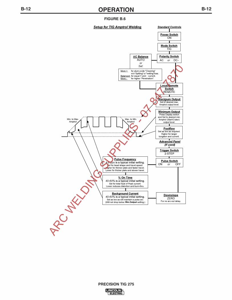
SETUP GUIDELINES FOR TIG WELDING
WITH AN AMPTROL
Both the Hand and Foot AMPTROLS work in a similarmanner. They are meant to be used for remote currentcontrol for TIG welding using the machineʼs 2-Step
trigger mode (See Item 12).
The Amptrol is capable of controlling the output of thePrecision TIG over the range between the level presetby the Minimum Output control when the Amptrol is atits inactivated state, and the level preset by theMaximum Output control when the Amptrol is at fully-activated state.
It is important to note that even with the Precision TIGʼsnew MicroStartTM Technology, some tungstens may bedifficult to start at the low (2 amps) minimum rating ofthe machine. Rather than guessing where to depressthe Amptrol to start the arc reliably, the Minimum
Output control allows presetting the exact level, soreliable starts, as well as minimum crater-fill levels, canbe consistently obtained at the minimum Amptrol (inac-tivated ) state. FIGURE B.6 shows Precision TIG setupfor TIG welding with an Amptrol.
PRECISION TIG 275
TIG WELD CYCLE CHART
SEE ITEM 12 SEE ITEM 12
SEE ITEM 7a
SEE ITEM 12 SEE ITEM 12
SEE ITEM 7
SEE ITEM 9SEE ITEM 17
SEE ITEM 16
SEE ITEM 15
SEE ITEM 15
SEE ITEM 14
SEE ITEM 7a
SEE ITEM 12
SEE ITEM 7a
SEE ITEM 7
SEE ITEM 6
SEE ITEM 6 & 7
SEE ITEM 12 & TIGWelding Features
ARC W
ELDIN
G SUPP
LIES
- 07 8
47 78
70
B-12OPERATIONB-12
PRECISION TIG 275
Max. to Min.
Amptrol
Min. to Max.
Amptrol
Setup for TIG Amptrol Welding
Advanced Panel(If used)
Standard Controls
Power SwitchON
Polarity SwitchAC or DC-
Mode SwitchTIG
AC BalanceAUTO
orSet:
More + for alum.oxide "Cleaning" w/o "Spitting" or "wetting" loss.
Balanced for equal + and - current.
More - for higher "Penetration".
Local/RemoteSwitch
REMOTE
Trigger Switch2-STEP
Pulse SwitchON or OFF
Pulse Frequency4-6 pps is a typical initial setting.
Set for bead shape and travel speed:
Higher for thinner plate and faster travel.
Lower for thicker plate and slower travel.
% On Time40-60% is a typical initial setting.
Set for total heat of Peak current:
Lower reduces distortion and burn-thru.
Background Current40-60% is a typical initial setting.
Set as low as will maintain a pulse arc
(Will not drop below Min.Output setting.)
DownslopeZERO
For no arc-out delay.
Minimum OutputPress Display switch
and Set to desired min.
Amptrol (Start/Crater)
output level.
PostflowSet as low as required.
Higher for larger
tungsten and current.
Maximum OutputSet to desired max.
Amptrol output level.
FIGURE B.6
ARC W
ELDIN
G SUPP
LIES
- 07 8
47 78
70
B-13OPERATIONB-13
PRECISION TIG 275
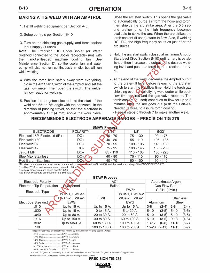
RECOMMENDED ELECTRODE AMPERAGE RANGES - PRECISION TIG 275
SMAW Process
ELECTRODE POLARITY 3/32" 1/8" 5/32"Fleetweld 5P, Fleetweld 5P+ DC+ 40 - 70 75 - 130 90 - 175Fleetweld 180 DC+ 40 - 80 55 - 110 105 - 135Fleetweld 37 DC+ 70 - 95 100 - 135 145 - 180Fleetweld 47 DC- 75 - 95 100 - 145 135 - 200Jet-LH MR DC+ 85 - 110 110 - 160 130 - 220Blue Max Stainless DC+ 40 - 80 75 - 110 95 - 110Red Baron Stainless DC+ 40 - 70 60 - 100 90 - 140Mild steel procedures are based on recommended procedures listed in C2.10 8/94 and the maximum rating of the PRECISION TIG 275Excaliber 7018 procedures are based on Jet-LH 78 MRBlue Max procedures are based on C6.1 6/95Red Baron Procedure are based on ES-503 10/93
GTAW Process
Electrode Polarity DC- AC* Approximate ArgonElectrode Tip Preparation Sharpened Balled Gas Flow Rate
Electrode Type EWZr C.F.H. (l/min.)EWTh-1, EWCe-2 EWTh-1, EWTh-2EWTh-2, EWLa-1 EWP EWCe-2, EWLa-1 Stainless
Electrode Size (in.) EWG EWG Aluminum Steel.010 Up to 15 A. Up to 15 A. Up to 15 A. 3-8 (2-4) 3-8 (2-4).020 Up to 15 A. 10 to 15 A. 5 to 20 A. 5-10 (3-5) 5-10 (3-5).040 Up to 80 A. 20 to 30 A. 20 to 60 A. 5-10 (3-5) 5-10 (3-5)1/16 Up to 150 A. 30 to 80 A. 60 to 120 A. 5-10 (3-5) 9-13 (4-6)3/32 Up to MAX. A. 60 to 130 A. 100 to 180 A. 13-17 (6-8) 11-15 (5-7)1/8 X 100 to 180 A. 160 to 250 A. 15-23 (7-11) 11-15 (5-7)
Tungsten electrodes are classified as follows by the American Welding Society (AWS):
Pure .........................................EWP...........green
+1% Thoria ..............................EWTh-1......yellow
+2% Thoria ..............................EWTh-2......red
+2% Ceria................................EWCe-2 .....orange
+1.5% Lanthana ......................EWLa-1......black
+0.15 to 0.40% Zirconia ..........EWZr..........brown
Ceriated Tungsten is now widely accepted as a substitute for 2% Thoriated Tungsten in AC and DC applications.
Balanced Wave, Unbalanced Wave requires derating of the electrode.
MAKING A TIG WELD WITH AN AMPTROL
1. Install welding equipment per Section A-5.
2. Setup controls per Section B-10.
3. Turn on the shielding gas supply, and torch coolantinput supply (if used).
Note: The Precision TIG Under-Cooler (or WaterSolenoid connected to the Cooler receptacle) runs withthe Fan-As-Needed machine cooling fan (SeeMaintenance Section D), so the cooler fan and waterpump will also not run continuously in idle, but will runwhile welding.
4. With the torch held safely away from everything,close the Arc Start Switch of the Amptrol and set thegas flow meter. Then open the switch. The welderis now ready for welding.
5. Position the tungsten electrode at the start of theweld at a 65° to 75° angle with the horizontal, in thedirection of pushing travel, so that the electrode isapproximately 1/8" (4 mm) above the work piece.
Close the arc start switch. This opens the gas valveto automatically purge air from the hose and torch,then shields the arc strike area. After the 0.5 sec-ond preflow time, the high frequency becomesavailable to strike the arc. When the arc strikes thetorch coolant (if used) starts to flow. Also, if weldingDC- TIG, the high frequency shuts off just after thearc strikes.
6. Hold the arc start switch closed at minimum AmptrolStart level (See Section B-10) until an arc is estab-lished, then increase the output to the desired weld-ing level and push the torch in the direction of trav-el.
7. At the end of the weld, decrease the Amptrol outputto the crater-fill level before releasing the arc startswitch to start the Postflow time. Hold the torch gasshielding over the solidifying weld crater while post-flow time expires and the gas valve reopens. Thetorch coolant (if used) continues to flow for up to 8minutes after the arc goes out (with the Fan-As-Needed feature) to assure torch cooling.• Repeat steps 5 through 7 to make another weld.
*
ARC W
ELDIN
G SUPP
LIES
- 07 8
47 78
70

C-1ACCESSORIESC-1
OPTIONAL EQUIPMENT
FACTORY INSTALLED OPTIONS
The basic Precision TIG 275 machine is factoryequipped with:
• A 3/8" Adapter (S20403-4) for air cooled torch con-nection of a PTA-9 or PTA-17.
FIELD INSTALLED OPTIONS
The following Options/Accessories are available for thePrecision TIG 275 and are installed per instructions inthis manual and / or provided in the package:
• K2621-1 Precision TIG Advanced Control PanelProvides 2/4-step trigger modes withadjustable Pulser/Spot controls and Downslope timer for TIG welding. Also allowsadjustable Hot Start and Arc Force Menusettings for Stick welding and Menu set-tings for TIG Hot Start and Upslope, as wellas other user selectable features.
• K1828-1 Under-Cooler Cart Includes a "cooler-in-a-drawer" with hoses and alockable storage drawer on a dual bottle undercar-riage (see below).
• K1869-1 UndercarriageIncludes a dual bottle rack with chain and an under-carriage with 5" front casters,10" rear wheels and ahandle.
• K1830-1 Water Solenoid KitProvides for stopping flow of external water supply.Connects to coolant inlet and cooler receptacle ofPrecision TIG.(Can not be used with a water cooler.)
• K870 Foot AmptrolSingle pedal foot activation of arc start switch andoutput control, with 25ʼ plug cable.
• K963-3 Hand AmptrolFastens to torch for convenient thumb activation ofarc start switch and output control, with 25ʼ plugcable:
• K814 Arc Start SwitchNeeded for TIG welding without an Amptrol. Includes25ʼ plug cable, and attaches to torch for convenientfinger control.
• K1831-1 Power Factor Capacitor KitUsed when welding at higher output currents toreduce input current and help keep electricity coststo a minimum.
• Magnum® PTA and PTW Series Torches
All Air Cooled or Water-Cooled Magnum® TIGTorches may be used with the PRECISION TIG 275.Connection adapters are only required for Air-CooledTorches (Refer to Diagrams on A-7):
K2166-1 7/8” Torch Connector for PTA-26 (onepiece)
K2166-2 1/2” stud Connector for PTA Torch (two-piece).
K2166-3 3/8” TIG Torch Connector for PTA-9,-17(one piece). (Included as S20403-4 with PrecisionTIG models.)
• 3100211 Harris Argon Flow Regulator (Includes 10ʼhose.)
• K2150-1 Work Lead Assembly15ft. 2/0 cable with 1/2" stud lug and work clamp.
PRECISION TIG 275
ARC W
ELDIN
G SUPP
LIES
- 07 8
47 78
70

D-1MAINTENANCED-1
PRECISION TIG 275
ELECTRIC SHOCK can kill.
• Only qualified personnel should
perform this maintenance.
• Turn the input power OFF at the
disconnect switch or fuse box
before working on this
equipment.
• Do not touch electrically hot
parts.
To avoid receiving a high frequency shock, keep theTIG torch and cables in good condition.
Very little routine maintenance is necessary to keepyour Precision TIG 275 running in top condition. Nospecific schedule can be set for performing the follow-ing items; factors such as hours of usage and machineenvironment should be considered when establishinga maintenance schedule.
• Periodically blow out dust and dirt which may accu-mulate within the welder using an air stream.
• Inspect welder output and control cables for fraying,cuts, and bare spots.
• Inspect the spark gap at regular intervals to maintainthe recommended spacing. See the ServiceProcedures (See Service Procedures in thisSection) for complete information on spark gap set-tings.
• The fan motor has sealed ball bearings whichrequire no maintenance.Overload Protection
SAFETY PRECAUTIONS
ROUTINE AND PERIODIC MAINTENANCE
WARNING
WARNING
OVERLOAD PROTECTION
FAN-AS-NEEDED (F.A.N.)
The Precision TIG 275 has the F.A.N. circuit feature,which means the cooling fan will operate only whilewelding; then for about 8 minutes after welding hasstopped to assure proper machine cooling. This helpsreduce the amount of dust and dirt drawn into themachine with the cooling air. The cooling fan will oper-ate briefly when the machine power is initially turnedon, and continuously while the yellow ThermalShutdown Light is lit (see Thermostatic Protection).
THERMOSTATIC PROTECTION
This welder has thermostatic protection from excessiveduty cycles, overloads, loss of cooling, and excessiveambient temperatures. When the welder is subjectedto an overload, or inadequate cooling, the primary coilthermostat and/or secondary coil thermostat will open.This condition will be indicated by the illumination ofthe yellow Thermal Shutdown Light on the front panel(see Item 10 in Section B). The fan will continue to runto cool the power source. Postflow occurs when TIGwelding is shut down, but no welding is possible untilthe machine is allowed to cool and the yellow ThermalShutdown Light goes out.
AUXILIARY POWER CIRCUIT BREAKER
This machine includes a 5 amp circuit breaker, locatedon the opposite side of the upper case back, for pro-tection of the 220vac Schuko type cooler receptacle.
ARC W
ELDIN
G SUPP
LIES
- 07 8
47 78
70

D-2MAINTENANCED-2
SERVICE PROCEDURES
Operation of the Precision TIG should be trouble-freefor the life of the machine. Should a malfunction occur,however, the following procedures will be useful totrained service personnel with experience in repairingarc welding equipment:
COMPONENT ACCESSThe following components are accessible for routineset up and periodic service without requiring removalof the case sides or roof:
• Input Reconnect Panel (refer Section A) is locatedbehind a removable panel on the rear of the left caseside. Remove the two screws (with a screwdriver ora 3/8"/ 9.5mm hex driver) on the bottom corners ofthis panel to remove it.
• Control Box components and PC Boards (referSection B Internal Set Up Controls) are locatedbehind the front control panel. Remove the twoscrews (with a screwdriver or a 3/8"/ 9.5mm hex dri-ver) on the top corners of this panel to swing it down.
• Hi-Freq. Spark Gap assembly (refer Spark GapAdjustment) is located behind a removable panel onthe rear of the right case side, under the torch box.Remove the screw (with a screwdriver or a 3/8"/9.5mm hex driver) on the bottom center of this panelto remove it.
SPARK GAP ADJUSTMENT
The spark gap is set at the factory to a gap of 0.015inches (0.4 mm) See Figure C.1. This setting is ade-quate for most applications. Where less high frequen-cy is desired, the setting can be reduced to 0.008 inch-es (0.2 mm).
Use extreme caution when working with circuit of
the high frequency. The high voltages developed
can be lethal. Turn the input power off using the
disconnect switch or fuse box before working
inside the machine. This is particularly important
when working on the secondary circuit of the high
voltage transformer (T3) because the output volt-
age is dangerously high.
------------------------------------------------------------------------
Note: In highly dirty environments where there is anabundance of conductive contaminants, use a lowpressure air stream or a firm piece of paper to cleanout the spark gap. Do not disturb the factory gap set-ting.
To check the spark gap:1. Turn the input power off per above.2. Remove the access panel on the right case side
(See Component Access).3. Check the spark gap spacing with a feeler gauge.
If adjustment is required:1. Adjust the gap by loosening the Allen head screw
on one of the aluminum blocks, reset the gap andtighten the screw in the new position.
If spark gap is correct:1. Reinstall the access panel on the right case side.
UNDER-COOLER SERVICE
The required maintenance and service instructions forthe Under-Cooler are provided in the operatorʼs manu-al (IM723) provided with the Under-Cooler Cart.
PRECISION TIG 275
.015 Spark Gap
FIGURE C.1 SPARK GAP
WARNING
ARC W
ELDIN
G SUPP
LIES
- 07 8
47 78
70

D-3MAINTENANCED-3
METER CALIBRATION ADJUSTMENT
The Precision TIG meter circuits are factory calibratedfor the accuracy of the ammeter and voltmeter (seeSection B Panel Control Functions), and should notneed adjustment. However, the factory trimmers areaccessible inside the control box (see Section DComponent Access):
• The Meter Board, located on the front panel of themachine, is digital and has no calibration capability.
• Ammeter Calibration Trimmer (R5) is located onthe Control PC Board (left of center near the top ofthe board). This trimmer adjusts calibration of theammeter circuit to the digital panel Meter, so it shouldbe checked after the Digital Meter check above. Theammeter calibration is checked as follows:
1. Set to TIG mode with DC- polarity andLOCAL control. Without closing the arc startswitch, preset the Maximum Output panelcontrol so the panel digital Meter readsabout 200 amps.
2. Using a DC (avg.) test ammeter with at least1% accuracy at up to 300 amps, connect itto measure the DC current through a shortweld cable shorting out the WORK (+) toELECTRODE (-) studs on the front studpanel. Remove the TIG torch, if connected.
3. Close the arc start switch just long enoughto compare the panel Meter reading to thatof the test ammeter. The short circuit currentreadings should match within 4%+/-2A. Ifnot, adjust the trimmer so that the panelmeter accuracy is corrected.
• Voltmeter Calibration Trimmer (R2) is located onthe Control PC Board (right of center near the top ofthe board). This trimmer adjusts calibration of thevoltmeter circuit to the digital panel Meter, so itshould be checked after the Digital Meter checkabove. The voltmeter calibration is checked as fol-lows:
1. To prevent maximum OCV output (which isnot precise for voltmeter checking) discon-nect the SCR gate lead plug from recepta-cle J4 on the lower left corner of the ControlPC board.
2. Set to TIG mode with DC- polarity withoutclosing the arc start switch.
3. Using a DC (avg.) test voltmeter with atleast 1% accuracy at up to 100 volts, con-nect it across the WORK (+) and ELEC-TRODE (-) studs on the front stud panel.Remove the TIG torch, if connected.
4. Press the DISPLAY panel switch to V (volts)position, then close the arc start switch justlong enough* to compare the panel Meterreading to that of the test volt meter. Theopen circuit voltage readings (about 50vdc)should match within 3%+/-1V. If not, adjustthe trimmer so that the panel meter accura-cy is corrected.
* If switch is held closed longer than about 15 secondsthe Precision TIG will shut down to protect internalholding resistor from overheating.
PRECISION TIG 275
ARC W
ELDIN
G SUPP
LIES
- 07 8
47 78
70

DO NOT use a volt-ohm meter to measure output voltages in TIG mode. TheHigh Frequency Arc Starter voltage can damage the meter.
CAUTION
E-1TROUBLESHOOTINGE-1
PRECISION TIG 275
If for any reason you do not understand the test procedures or are unable to perform the tests/repairs safely, contact your Local
Lincoln Authorized Field Service Facility for technical troubleshooting assistance before you proceed.
CAUTION
This Troubleshooting Guide is provided to help youlocate and repair possible machine malfunctions.Simply follow the three-step procedure listed below.
Step 1. LOCATE PROBLEM (SYMPTOM).
Look under the column labeled “PROBLEM (SYMP-TOMS)”. This column describes possible symptomsthat the machine may exhibit. Find the listing that bestdescribes the symptom that the machine is exhibiting.
Step 2. POSSIBLE CAUSE.
The second column labeled “POSSIBLE CAUSE” liststhe obvious external possibilities that may contribute tothe machine symptom.
Step 3. RECOMMENDED COURSE OF ACTION
This column provides a course of action for thePossible Cause, generally it states to contact yourlocal Lincoln Authorized Field Service Facility.
If you do not understand or are unable to perform theRecommended Course of Action safely, contact yourlocal Lincoln Authorized Field Service Facility.
HOW TO USE TROUBLESHOOTING GUIDE
Service and Repair should only be performed by Lincoln Electric Factory Trained Personnel.Unauthorized repairs performed on this equipment may result in danger to the technician and machineoperator and will invalidate your factory warranty. For your safety and to avoid Electrical Shock, pleaseobserve all safety notes and precautions detailed throughout this manual.
__________________________________________________________________________
WARNINGAR
C WEL
DING S
UPPLIE
S - 0
7 847
7870

E-2TROUBLESHOOTINGE-2
PRECISION TIG 275
Observe all Safety Guidelines detailed throughout this manual
If for any reason you do not understand the test procedures or are unable to perform the tests/repairs safely, contact your Local
Lincoln Authorized Field Service Facility for technical troubleshooting assistance before you proceed.
CAUTION
OUTPUT PROBLEMS
PROBLEMS
(SYMPTOMS)
POSSIBLE
CAUSE
RECOMMENDED
COURSE OF ACTION
Thermal light comes on
Meter doesnʼt light up
Has output in No gas & no hi-freqStick mode but no output in Tig mode
Gas & hi-freq are o.k.
No output in both Stick and Tigmodes
1. Thermal shut down. Dirt and dustmay have clogged the coolingchannels inside machine; airintake and exhaust louvers maybe blocked; welding applicationmay exceed recommended dutycycle. Wait until machine cooldown and thermal light goes out.Blow out machine with clean, drylow pressure air; check air intakeand louvers; stay within recom-mended duty cycle.
2. Bad thermostat or its connections
1. Losing AC supply to Control PCboard
2. Loosing input to machine
3. Faulty Control PC board
1. Faulty trigger or hand/foot Amptrolor connections.
2. Faulty Protection PC board orbad connection to Control PCboard
3. Losing trigger supply to ControlPC board
1. Faulty Control PC board
1. Bad connection at P4 of ControlPC board
2. Faulty Control PC board
If all recommended possible areasof misadjustment have beenchecked and the problem persists,Contact your local LincolnAuthorized Field Service Facility.
ARC W
ELDIN
G SUPP
LIES
- 07 8
47 78
70

E-3TROUBLESHOOTINGE-3
PRECISION TIG 275
Observe all Safety Guidelines detailed throughout this manual
If for any reason you do not understand the test procedures or are unable to perform the tests/repairs safely, contact your Local
Lincoln Authorized Field Service Facility for technical troubleshooting assistance before you proceed.
CAUTION
METER PROBLEMS
PROBLEMS
(SYMPTOMS)
POSSIBLE
CAUSE
RECOMMENDED
COURSE OF ACTION
Meter does not light up
Meter does not display V (Volt) orMin A (Minimum current)
No gas
No control on post flow time
Pre flow & Post flow time too long
1. Bad meter or its connection.
2. Bad connection at P13 of ControlPC board.
3. Faulty Control PC board.
1. Bad Display switch or its connec-tion.
2. Bad connection at P9 of ControlPC board.
1. Circuit breaker CB1 open. PressCB1 in to reset.
2. Bad connection at P12 of ControlPC board.
3. Faulty gas solenoid valve SV1 orits connection.
4. Faulty Control PC board.
1. Faulty potentiometer R3 or itsconnection.
2. Bad connection at P9 of ControlPC board.
1. For Postflow; the DIP switch set-ting on the Advanced Control PCB(if installed) may be set for time x2.Check DIP switch setting.
2. For Preflow; Menu setting toolong. Check Menu setting.
3. Missing plug P3 on Control boardor bad connection of P3 toAdvanced Control PCB.
If all recommended possible areasof misadjustment have beenchecked and the problem persists,Contact your local LincolnAuthorized Field Service Facility.
If all recommended possible areasof misadjustment have beenchecked and the problem persists,Contact your local LincolnAuthorized Field Service Facility.
GAS PROBLEMS
ARC W
ELDIN
G SUPP
LIES
- 07 8
47 78
70

E-4TROUBLESHOOTINGE-4
PRECISION TIG 275
Observe all Safety Guidelines detailed throughout this manual
If for any reason you do not understand the test procedures or are unable to perform the tests/repairs safely, contact your Local
Lincoln Authorized Field Service Facility for technical troubleshooting assistance before you proceed.
CAUTION
HI-FREQ PROBLEMS
PROBLEMS
(SYMPTOMS)
POSSIBLE
CAUSE
RECOMMENDED
COURSE OF ACTION
No hi-freq
Hi-freq intensity too weak
Hi-freq on continuously in DC Tig
Hi-freq shuts off after starting in ACTig
1. Circuit breaker CB1 open
2. Bad connection at P12 of ControlPC board
3. Spark gaps shorted
4. Faulty Control PC board
1. Dirty spark gap or improper gapsetting
2. Faulty Arc Starter assembly
1. Bad connection at P11 of ControlPC board
2. Micro-switch S2A is not engaged &disengaged properly when switch-ing between DC & AC polarity.(S2A locates on the Polarityswitch)
3. Faulty Control PC board
1. Micro-switch S2A is not engaged &disengaged properly when switch-ing between DC & AC polarity.(S2A locates on the Polarityswitch)
If all recommended possible areasof misadjustment have beenchecked and the problem persists,Contact your local LincolnAuthorized Field Service Facility.
ARC W
ELDIN
G SUPP
LIES
- 07 8
47 78
70

E-5TROUBLESHOOTINGE-5
PRECISION TIG 275
Observe all Safety Guidelines detailed throughout this manual
If for any reason you do not understand the test procedures or are unable to perform the tests/repairs safely, contact your Local
Lincoln Authorized Field Service Facility for technical troubleshooting assistance before you proceed.
CAUTION
PRESET & OUTPUT CONTROL PROBLEMS
PROBLEMS
(SYMPTOMS)
POSSIBLE
CAUSE
RECOMMENDED
COURSE OF ACTION
Meter does not display preset
High output current in both DC & ACpolarities regardless of preset
High output current in DC polarityregardless of preset, o.k. in AC polar-ity
In 2-step Tig, output stays on formore than downslope time after trig-ger open (machine with AdvancedControl panel only)
Output stays on after releasinghand/foot Amptrol (machine withAdvanced Control panel only)
1. Faulty potentiometer R1 or its con-nection
2. Bad connection at P9 of ControlPC board
3. Faulty Advanced Control PC board( if present ) or its connection tothe main Control PC board
4. Missing plug P3 on Control boardor bad connection at P3 when anAdvanced Control PC board is notpresent
1. Bad connection at P6 of ControlPC board
2. Bad shunt connection
3. Faulty Control PC board
4. Faulty SCR bridge
1. Shorted free wheeling diode D1
1. Bad 2/4 step switch or its connec-tion
2. Bad connection at P1 of AdvancedControl PC board
1. Downslope is not set at min.
2. Bad Downslope potentiometerR12 or its connection
If all recommended possible areasof misadjustment have beenchecked and the problem persists,Contact your local LincolnAuthorized Field Service Facility.
ARC W
ELDIN
G SUPP
LIES
- 07 8
47 78
70

E-6TROUBLESHOOTINGE-6
PRECISION TIG 275
Observe all Safety Guidelines detailed throughout this manual
If for any reason you do not understand the test procedures or are unable to perform the tests/repairs safely, contact your Local
Lincoln Authorized Field Service Facility for technical troubleshooting assistance before you proceed.
CAUTION
STICK WELDING PROBLEMS
PROBLEMS
(SYMPTOMS)
POSSIBLE
CAUSE
RECOMMENDED
COURSE OF ACTION
Stick electrode "blast off" when arcis struck
Stick electrode "sticks" in the weldpuddle
Poor starting in DC polarity
Arc "flutters" in DC polarity, o.k. inAC polarity
Arc "flutters" in both DC & AC polari-ties
1. Current may be set too high forelectrode size
2. (Machine with Advanced ControlPC board only) Hot Start Menusetting too high
1. Current may be set too low forelectrode size
2. (Machine with Advanced ControlPC board only) Arc Force Menusetting too low
1. Input line may be too low
2. Bad connection at P11 of ControlPC board
3. Bad Background rectifier, back-ground resistor R7, or backgrounddiode D2
1. Tungsten not "sharp"
2. Bad free wheeling diode D1 or itsconnection
1. Tungsten electrode may be toolarge in diameter for the currentsetting
2. Gas shielding may be insufficient.
3. Contaminated gas or leaks in thegas line, torch, or connections
4. Helium blend is used as a shield-ing gas
If all recommended possible areasof misadjustment have beenchecked and the problem persists,Contact your local LincolnAuthorized Field Service Facility.
If all recommended possible areasof misadjustment have beenchecked and the problem persists,Contact your local LincolnAuthorized Field Service Facility.
TIG WELDING PROBLEMS
ARC W
ELDIN
G SUPP
LIES
- 07 8
47 78
70

E-7TROUBLESHOOTINGE-7
PRECISION TIG 275
Observe all Safety Guidelines detailed throughout this manual
If for any reason you do not understand the test procedures or are unable to perform the tests/repairs safely, contact your Local
Lincoln Authorized Field Service Facility for technical troubleshooting assistance before you proceed.
CAUTION
TIG PROBLEMS
PROBLEMS
(SYMPTOMS)
POSSIBLE
CAUSE
RECOMMENDED
COURSE OF ACTION
Arc "pulsates" in AC polarity, DCpolarity is o.k.
Black area along weld bead
Output quits momentarily; gas flowand hi-freq are also interrupted
1.Micro switch S2A on polarity switchdoes not open in AC polarity
1. Oily or organic contamination fromwork piece
2. Tungsten electrode may be conta-minated
3. Leaks in gas line, torch, or con-nections
1. May be caused by hi-freq interfer-ence. Check that machine isgrounded properly. Surroundingmachines that generate hi-freqalso should be properly grounded.
2. Ground connection of ProtectionPC board may has become loose
3. Ground connection ofBypass/Stabilizer PC board mayhas become loose.
If all recommended possible areasof misadjustment have beenchecked and the problem persists,Contact your local LincolnAuthorized Field Service Facility.
ARC W
ELDIN
G SUPP
LIES
- 07 8
47 78
70

F-1WIRING DIAGRAMF-1
PRECISION TIG 275
RE
CE
PT
AC
LE
CA
BB
10K
A-B
FEDC
MIN
IMU
M
D F
TM
AM
PT
RO
L
A
E
RE
MO
TE
A B C D E F
+-
GR
GY
8
4 1 2 3 6 56
BW
+-
BW
+-
BW
+-
BW
+-
G
331
654321 2 3 4 5 71
87 654321
J23
J22
321
322
313
314
315
316
317
318
319
320
311
312
J8 J9
5983721 6 4
331
10
411
W403
404
405
406
407
408
409
410
401
402
87654321
220
G1
217
21W
22
1R
222
11310226
927
027
122
9A
65 4321
233A
235
16815714413512691
J11
L8
J10
J1
J5
J12J4J6
N.A
.
862 3 4 5 71
J5A
N.B
.
260
236
521 3
J7
401D
402403
405406
408
409
410
401B
401C
401D
232
H5
(440
V)
F
W20
9
18V
AC
X7
R21
0
201
X8
FS
X5 X2
X1
T1
78V
AC
S
204
115V
AC
X9
X10 20
VA
C
X3
H4
(415
V)
H2
(220
V)
X6
262
263
63.5
VA
C
CR
4
231A
231
115V
AC
X4
CB
1
15A
232
231
SFS
FS
CR
4
233B
234
48
26
233
01
233A
C8
C9
214
213
233A
231A
269
229A
271
270
229
262
263
201
204
W20
9R
210
115V
AC
R5
SV
1
L3
C6
T2
C7
T3
GA
PS
PA
RKL2
237
S F
R6
FA
N
260
235
233A
239238
284
285
236B
236
231D
231E
231A
231E
233A
PO
S
D
NEG
S2
NO
X2
NC
TO
GR
OU
ND
PE
R
CG
266A
S2
A
265A
HA
L1
E
F
ELE
CT
RIC
AL
CO
DE
NA
TIO
NA
L
253
PO
S
B
252
W 221R 222
265
266
G4
G3
G2
213
214
201
204
W20
9R
210
262
263
265
266
252
253
G1
G2
217
216 22
0
G3
220A
G4
218
SC
R4
D1
X1 NEG
SC
R3
PO
S
(+)
SC
R1
SC
R2
252
(-)
B
G56
92-2A.
02
L9L10
L7
L6
L5
L12
L4
L13
L11
J3
N.D
.
N.C
.
C1
H4
H2
H1
H3
S1
H1
C2
HIG
H
MID
LOW
CO
M
251
21
34
56
89
107
21
34
56
89
107
J2J3
21
34
56
89
107
OR
N.C
.
407
L1 (
U)
L2 (
V)
319
322
313C
316B315
316317
311312
313318
313B
321
314320
311A
316A
316C
311A
316A316B
F
C
S
E
N.E
.
332
333
BW
334
335
BW
332
BW
333
BW
334
BW
335
BW
1211109865431 2 7
1211109865431 2 7
64
10921
621
8
SV
2
105V
AC
50A
F X
1452
CB
1
15A
52
CB
25A
51
5022
0VA
C
N.F
.
H3
(380
V)
250
A
250
L1 (
U)
L2 (
V)
L1A
L2A
313A
217A
R7C
218B
R7D
271A
218A
R7A
230
R7B
268
R8B
216A
216A 21
8A
217A
GN
D6
GND6
344
345
343
432134
7
J731
6D
346
S3
862 3 4 5 71
J13
343
344
345
346
347
G+
-
W
B
401
404
411
401A
401B
R+
-B
W
413
413
W21
J20
229
316C
N.A
. CO
NNE
CTI
ON
IS P
IN T
O P
IN B
ETW
EEN
J23
AND
J5.
N.B
. RO
BOTI
C IN
TER
FACE
CO
NNE
CTI
ON.
N.C
. REM
OVE
JU
MPE
R PL
UG
IN J
3 W
HEN
INST
ALLI
NG
TIG
OPT
ION
PC
BOAR
D.
N.D
. DIS
CO
NNE
CT
JUM
PER
LEAD
BET
WEE
N PI
N 1
AND
PIN
2 IN
J3
TO D
OU
BLE
PREF
LOW
& P
OST
FLOW
TIM
ES.
N.E
. DI
SPLA
Y TO
GG
LE S
HO
WN
IN M
IN A
MP
POSI
TIO
N.
N.F
. PL
UG
S IN
TO L
OW
ER S
WIT
CHE
D RE
CEPT
ACLE
.
TO
GR
OU
ND
PE
RN
AT
ION
AL
ELE
CT
RIC
CO
DE
GN
D4
GN
D5
GN
D1
REC
ON
NECT
PAN
ELPA
NNEA
U D
E R
ECO
NNE
XION
PANE
L D
E R
ECO
NEX
IÓN
T1
BA
CK
AR
RIE
ÉR
EP
OS
TE
RIO
R
FR
ON
TA
VA
NT
FR
ON
TA
L
CO
NT
RO
L P
AN
EL
PA
NN
EA
U D
E C
OM
MA
ND
EP
AN
EL
DE
CO
NT
RO
L
115
VA
CR
EC
.S
V1
GN
D6
GN
D-H
2G
ND
-H
220
VA
CR
EC
.
A L
A T
ER
RE
SE
LON
LE
CO
DE
ÉLE
CT
RIQ
UE
NA
TIO
NA
LA
TIE
RR
A C
ON
FO
RM
E E
L C
ÓD
IGO
ELE
CT
RIC
O N
AC
ION
AL
N.A
. C
ON
NEXI
ON
CO
NTA
CT-
CO
NTA
CT
ENTR
E J2
3 ET
J5
N.B
. C
ON
NEXI
ON
INTE
RFA
CE R
OBO
TIQU
EN
.C.
ENLE
VER
LA F
ICHE
CAV
ALIE
R EN
J3
QUA
ND O
N IN
STAL
LE L
E CI
EN
O
PTIO
N T
IGN
.D.
DÉC
ON
NEC
TER
LE C
ÂBLE
DU
CAV
ALIE
R EN
TRE
LES
CO
NTA
CTS
1 E
T
2 DA
NS J
3 PO
UR D
OUB
LER
TEM
PS D
E PR
ÉGAZ
ET
POST
GAZ
.N
.E.
AFFI
CHE
LA
BASC
ULE
ILLU
STRÉ
E EN
PO
SITI
ON
A M
INIM
UM
.N
.F.
SE B
RANC
HE L
A PR
ISE
À IN
TERR
UPTE
UR IN
FÉRI
EUR
E.
GND6
ME
TE
RC
OM
PT
EU
RM
ED
IDO
R
MIN
DIS
PLA
YA
FF
ICH
AG
EP
AN
TA
LLA
MA
X
FR
EQ
BA
CK
GR
OU
ND
AR
RIÈ
RE
PLA
NF
ON
DO
BYPA
SS/S
TABI
LIZE
R P
C B
OAR
DC
I DÉR
IVAT
ION
/STA
BILI
SATE
UR
BYPA
SS P
C B
OARD
CI D
ÉRIV
ATIO
NTA
RJE
TA E
LEC
TRO
NIC
A D
ED
ERIV
ACIÓ
N
ÉC
LAT
EU
RA
BE
RT
UR
AD
E C
HIS
PA
CO
NT
RO
L P
AN
EL
(V
IEW
ED
FR
OM
RE
AR
)P
AN
NE
AU
DE
CO
MM
AN
DE
(V
IEW
ED
FR
OM
RE
AR
)P
AN
EL
DE
CO
NT
RO
L (V
IST
O D
ES
DE
AT
RÁ
S)
AD
VA
NC
ED
CO
NT
RO
L P
AN
EL
(OP
TIO
NA
L)P
AN
NE
AU
DE
CO
MM
AN
DE
AV
AN
CÉ
(O
PT
ION
)P
AN
EL
DE
CO
NT
RO
L A
VA
NZ
AD
O (
OP
CIO
NA
L)
PR
OT
EC
TIO
N P
CB
CI P
RO
TE
CT
ION
PC
B D
EP
RO
TE
CC
IÓN
PR
ISE
À D
IST
AN
CE
RE
CE
PT
ÁC
ULO
RE
MO
TO
TIG OPTION PCBCI OPTION TIG
PCB DE OPCIÓNTIG
CO
NT
RO
L P
C B
OA
RD
CI D
E C
OM
MA
ND
ET
AB
LEA
U D
ET
AR
JET
A E
LEC
TR
ON
ICA
DE
CO
NT
RO
L
PR
EC
ISIO
N T
IG 2
75 W
IRIN
G D
IAG
RAM
SC
HÉ
MA
DE
CÂ
BL
AG
E
DIA
GR
AM
AS
DE
CA
BL
EA
DO
GR
OU
ND
TER
RETI
ERRA
RE
CO
NN
EC
T P
AN
EL
PA
NN
EA
U D
E R
EC
ON
NE
XIO
NP
AN
EL
DE
RE
CO
NE
XIÓ
N
A L
A T
ER
RE
SE
LON
LE
CO
DE
ÉLE
CT
RIQ
UE
NA
TIO
NA
LA
TIE
RR
A C
ON
FO
RM
E E
L C
ÓD
IGO
ELÉ
CT
RIC
O N
AC
ION
AL
N.A
. LA
CO
NEX
IÓN
ES D
E PI
N A
PIN
ENTR
E J2
3 Y
J5.
N.B
. C
ON
EXIÓ
N DE
LA
INTE
RFA
Z R
OBÓ
TICA
.N
.C.
REM
UEVA
EL
CO
NEC
TOR
DE
PUEN
TE E
N J3
CU
AND
O IN
STAL
E LA
TA
RJE
TA D
E PC
TIG
OPC
IONA
L.N
.D. D
ESC
ON
ECTE
EL
CAB
LE D
EL P
UEN
TE E
NTR
E EL
PIN
1 Y
PIN
2 E
N J3
PA
RA D
UPL
ICAR
LO
S TI
EMPO
S DE
PRE
Y P
OST
FLUJ
O.
N.E
. EL
INTE
RRUP
TOR
DE P
ALAN
CA
DE L
A PA
NTA
LLA
SE M
UEST
RA E
N LA
PO
SICI
ÓN
MÍN
IMA
DE
AMPE
RIO
S.N
.F.
ENC
HU
FES
EN R
ECEP
TÁCU
LO C
ON
MU
TAD
O IN
FERI
OR.
415
VC
ON
NEC
T ST
RAP
TO H
IGH
(H4)
(AS
SH
OW
N)
CO
NNE
CTE
R L
A BR
IDE
SUR
HAU
T (H
4)(C
OM
ME
ILLU
STRÉ
)SU
JETA
DO
R D
E C
ONE
XIÓ
N A
ALT
O (H
4)(C
OM
O S
E M
UEST
RA)
380-
400V
CO
NNE
CT
STRA
P TO
MID
(H3)
CO
NNE
CTE
R LA
BR
IDE
SUR
MO
YEN
(H3)
SUJE
TAD
OR
DE
CO
NEXI
ÓN
A M
EDIO
(H3)
220-
230V
CO
NNE
CT
STRA
P TO
LO
W (H
2)C
ON
NEC
TER
LA B
RID
E SU
R B
AS (H
2)SU
JETA
DO
R D
E C
ONE
XIÓ
N A
BAJ
O(H
2)
ARC
STA
RTE
R A
S'BL
YEN
SEM
BLE
DÉM
ARRE
UR
D'A
RC
ENSA
MBL
E DE
AR
RAN
CAD
OR
DE
ARC
O
REAR
ELEC
TRO
DE
ÉLEC
TRO
DE A
RRIÈ
REEL
ECTR
OD
O P
OST
ERIO
R
FRO
NT
ELEC
TRO
DE
ÉLEC
TRO
DE A
VAN
TEL
ECTR
OD
O F
RO
NTA
L
WO
RK
PIÈC
ETR
ABAJ
O
TAR
JETA
ELE
CTR
ON
ICA
DED
ERIV
ACIÓ
N /
ESTA
BILI
ZAD
OR
VEN
TILA
TEU
RVE
NTI
LAD
OR
T1 P
RIM
ARY
THER
MO
STAT
T1 P
RIM
AIR
ETH
ERM
OST
ATTE
RM
OST
ATO
PRIM
ARIO
DEL
T1
T1 S
ECON
DAR
YTH
ERM
OST
ATT1
SEC
OND
AIR
ETH
ERM
OST
ATTE
RM
OST
ATO
SECU
NDAR
IOD
EL T
1
A-C
, D-E
, B-F
B-D
, C-E
, A-F
, G-H
DC
+D
C-
AC
B-D
, A-E
, C-F
, G-H
S
2
S
2A
CLO
SE
D F
ER
MÉ
CE
RR
AD
OO
PE
N O
UV
ER
T A
BIE
RT
O
CLO
SE
D F
ER
MÉ
CE
RR
AD
O
VIEW
OF
CON
NEC
TOR
ON
PC
BO
ARD
ELE
CT
RIC
AL
SY
MB
OLS
PE
R E
1537
.S
YM
BO
LES
ÉLE
CT
RIQ
UE
S S
ELO
N E
1537
SÍM
BO
LOS
ELÉ
CT
RIC
OS
CO
NF
OR
ME
A E
1537
CO
MP
ON
EN
T V
ALU
E U
NIT
S:
RE
SIS
TO
RS
: OH
MS
/WA
TT
SC
AP
AC
ITO
RS
: MF
D/V
OLT
S
80F
CO
NN
EC
TO
R J
5E
XA
MP
LE:
TH
IS IS
PIN
1
32
21 8
CO
NNE
CTO
R P
IN N
UMB
ERS:
NO
MBR
E DE
CO
NTA
CTS
CO
NNE
CTE
URS
NÚ
MER
OS
DE P
INES
DE
CO
NEC
TOR
ES:
7 141
3
J5
UN
ITÉ
S D
E V
AL
EU
R D
ES
CO
MP
OS
AN
TS
:R
ÉS
IST
AN
CE
S: O
HM
S/W
AT
TS
CO
ND
EN
SA
TE
UR
S:
MF
D/V
OLT
S
EX
EM
PLE
: C'E
ST
LE
CO
NT
AC
T 1
DU
CO
NN
EC
TE
UR
J5
EJE
MP
LO: E
ST
E E
S E
L P
IN 1
DE
LC
ON
EC
TO
R J
5VU
E DE
S C
ON
NEC
TEUR
S SU
R C
IVI
STA
DEL
CO
NEC
TOR
EN
LATA
RJE
TA E
LEC
TRO
NIC
A
UN
IDA
DE
S D
E V
ALO
R D
E C
OM
PO
NE
NT
ES
:R
ES
IST
OR
ES
: O
HM
S/W
AT
TS
CA
PA
CIT
OR
ES
: M
FD
/VO
LTIO
S
LEA
D C
OLO
RIN
G C
OD
E:
CO
DE
DE
CO
ULE
UR
DE
S C
ÂB
LES
:C
ÓD
IGO
DE
CO
LOR
ES
DE
CA
BLE
S:
B-BL
ACK
N
OIR
N
EGR
O
O-O
RAN
GE
NAR
ANJA
G-G
REE
N
VER
T
VER
DE
R-R
ED
RO
UG
E
RO
JOB-
BLUE
B
LEU
A
ZUL
W-W
HITE
B
LANC
B
LANC
OY-
YELL
OW
J
AUN
E
AM
ARIL
LO
C1,
C2
POW
ER F
ACTO
R C
APAC
ITO
RS,
50/
460
C4,
C5
BY-P
ASS
CAP
ACIT
OR
S, .0
047
C6
HIG
H V
OLT
AGE
CAP
ACIT
OR
, .00
15/1
2kV
C7
PHAS
E SH
IFT
CAP
ACIT
OR
, 15
uF/2
50VA
CC
8,C
9H
IGH
FR
EQ P
RO
TEC
TIO
N C
APAC
ITO
RS,
.22/
400
CB1
CIR
CU
IT B
REA
KER
, 15
AMP
CB2
CIR
CU
IT B
REA
KER
, 5 A
MP
CR
412
V D
C R
ELAY
CO
ILD
1FR
EE W
HEE
LIN
G D
IOD
EL1
OU
TPU
T IN
DU
CTO
R (C
HO
KE)
L2,L
3H
IGH
FR
EQ IN
DU
CTO
RS
L4 -L
13R
F TO
RO
ID C
HO
KES
R5
PHAS
E SH
IFT
RES
ISTO
R, 2
00/1
00R
6H
OLD
ING
RES
ISTO
R, 5
0/22
5
S1IN
PUT
POW
ER S
WIT
CH
S2PO
LAR
ITY
SWIT
CH
S2A
MIC
RO
SWIT
CH
ON
PO
LAR
ITY
SWIT
CH
S3M
ENU
SW
ITC
HSC
R1,
2,3,
4M
AIN
PO
WER
SC
R'S
SV1
GAS
SO
LEN
OID
VAL
VE, 1
15VA
CSV
2W
ATER
SO
LEN
OID
VAL
VE, 1
15VA
C (O
PTIO
NAL
)T1
MAI
N T
RAN
SFO
RM
ERT2
HIG
H V
OLT
AGE
TRAN
SFO
RM
ERT3
HIG
H F
REQ
TR
ANSF
OR
MER
CO
ND
ENSA
TEU
RS
FAC
TEU
R D
E PU
ISSA
NC
E, 5
0/46
0C
APAC
ITO
RES
DE
FAC
TOR
DE
POTE
NC
IA, 5
0/46
0 C
4,C
5C
ON
DEN
SATE
UR
S D
ÉRIV
ATIO
N ,
.004
7C
APAC
ITO
RES
DE
DER
IVAC
IÓN
, .00
47C
ON
DEN
SATE
UR
HAU
TE T
ENSI
ON
, .00
15/1
2kV
CAP
ACIT
OR
DE
ALTO
VO
LTAJ
E, .0
015/
12kV
CO
ND
ENSA
TEU
R, D
ÉPH
ASAG
E, 1
5Mf/2
50VC
AC
APAC
ITO
R D
E C
AMBI
O D
E FA
SE 1
5uf/2
50VC
AC
ON
DEN
SATE
UR
S D
E PR
OTE
CTI
ON
HF,
.22/
400
CAP
ACIT
OR
ES D
E PR
OTE
CC
IÓN
CO
NTR
A AL
TA
FREC
UEN
CIA
, .22
/400
DIS
JON
CTE
UR
, 15
AMP
INTE
RR
UPT
OR
AU
TOM
ÁTIC
O, 1
5 AM
PSD
ISJO
NC
TEU
R, 5
AM
PIN
TER
RU
PTO
R A
UTO
MÁT
ICO
, 5 A
MPS
CR
4BO
BIN
E R
ELAI
DE
12V
CC
BOBI
NA
DE
REL
EVAD
OR
DE
12V
DE
DC
DIO
DE
RO
UE
LIBR
ED
IOD
O D
E R
UED
A LI
BRE
L1IN
DU
CTE
UR
DE
SOR
TIE
(STA
RTE
R)
IND
UC
TOR
DE
SALI
DA
(EST
ABIL
IZAD
OR
)IN
DU
CTA
NC
ES H
FIN
DU
CTO
RES
DE
ALTA
FR
ECU
ENC
IAL4
-L13
STAR
TER
S TO
RO
ÏDE
FRÉQ
UEN
CE
RAD
IO
ES
TABI
LIZA
DO
RES
TO
RO
IDAL
RF
RÉS
ISTA
NC
E D
ÉPH
ASAG
E, 2
00/1
00R
ESIS
TOR
DE
CAM
BIO
DE
FASE
, 200
/100
RÉS
ISTA
NC
E D
E M
AIN
TIEN
, 50/
225
RES
ISTO
R D
E SO
STEN
IMIE
NTO
, 50/
225
R7A
,R7B
, R
7C,R
7D,
R8A
, R8B
RÉS
ISTA
NC
E, 5
/50,
RES
ISTO
RES
, 5/5
0
INTE
RR
UPT
EUR
DE
PUIS
SAN
CE
D’E
NTR
ÉE
INTE
RR
UPT
OR
DE
ENER
GÍA
DE
ENTR
ADA
INTE
RR
UPT
EUR
DE
POLA
RIT
É
INTE
RR
UPT
OR
DE
POLA
RID
ADM
ICR
OR
UPT
EUR
SU
R S
ÉLEC
TEU
R D
E PO
LAR
ITÉ
MIC
RO
INTE
RR
UPT
OR
EN
EL
INTE
RR
UPT
OR
DE
POLA
RID
ADIN
TER
RU
PTEU
R M
ENU
INTE
RR
UPT
OR
DE
MEN
ÚR
EDR
ESSE
UR
S D
E PU
ISSA
NC
E PR
INC
IPAU
XSC
R'S
DE
ALIM
ENTA
CIÓ
N P
RIN
CIP
ALSV
1SO
UPA
PE S
OLÉ
NO
ÏDE
DE
GAZ
, 115
VAC
VÁLV
ULA
DE
SOLE
NO
IDE
DE
GAS
, 115
VC
ASO
UPA
PE S
OLÉ
NO
ÏDE
À EA
U, 1
15 V
AC
VÁLV
ULA
DE
SOLE
NO
IDE
DE
AGU
A, 1
15 V
CA
T1TR
ANSF
OR
MAT
EUR
PR
INC
IPAL
TRAN
SFO
RM
ADO
R P
RIN
CIP
ALTR
ANSF
OR
MAT
EUR
HAU
TE T
ENSI
ON
TRAN
SFO
RM
ADO
R D
E AL
TO V
OLT
AJE
TRAN
SFO
RM
ATEU
R H
AUTE
FR
ÉQU
ENC
ETR
ANSF
OR
MAD
OR
DE
ALTA
FR
ECU
ENC
IA
RES
ISTO
R, 5
/50
C1,
C2
C6
C7
R7A
, R7B
, R
7C, R
7D,
R8A
, R8B
C8,
C9
CB1
D1
L2,L
3
CB2
R5
R6
S1 S2 T2 T3S2A
S3 SCR
1,2,
3,4
SV2
PR
EC
ISIO
N T
IG 2
75 W
IRIN
G D
IAG
RA
M F
OR
CO
DE
111
60
SC
HÉ
MA
DE
CÂ
BL
AG
E P
AR
A E
L C
ÓD
IGO
111
60 D
IAG
RA
MA
S D
E C
AB
LE
AD
O P
OU
R L
E C
OD
E 1
1160
NO
TE
: T
his
dia
gra
m is
fo
r re
fere
nce
onl
y.
It m
ay n
ot
be
accu
rate
fo
r al
l mac
hine
s co
vere
d b
y th
is m
anua
l. T
he s
pec
ific
dia
gra
m f
or
a p
artic
ular
co
de
is p
aste
din
sid
e th
e m
achi
ne o
n o
ne o
f th
e en
clo
sure
pan
els.
If
the
dia
gra
m is
ille
gib
le, w
rite
to
the
Ser
vice
Dep
artm
ent
for
a re
pla
cem
ent.
G
ive
the
equi
pm
ent
cod
e nu
mb
er..
ARC W
ELDIN
G SUPP
LIES
- 07 8
47 78
70

F-2DIMENSION PRINTF-2
PRECISION TIG 275
L116
60XB
-UF
** L
OCA
TIO
N O
F (4
) O
.284
BAS
E M
OUN
TING
HO
LES.
12.7
7
31.0
0
26.0
0
1.00
24.0
0**
.28
3.47
20.5
0**
22.0
0
.30
.75
3.44
TORC
H HO
LSTE
R
2.11
TORC
H BO
X
11.0
0
2.98
ARC W
ELDIN
G SUPP
LIES
- 07 8
47 78
70

NOTES
PRECISION TIG 275
ARC W
ELDIN
G SUPP
LIES
- 07 8
47 78
70

NOTES
PRECISION TIG 275
ARC W
ELDIN
G SUPP
LIES
- 07 8
47 78
70
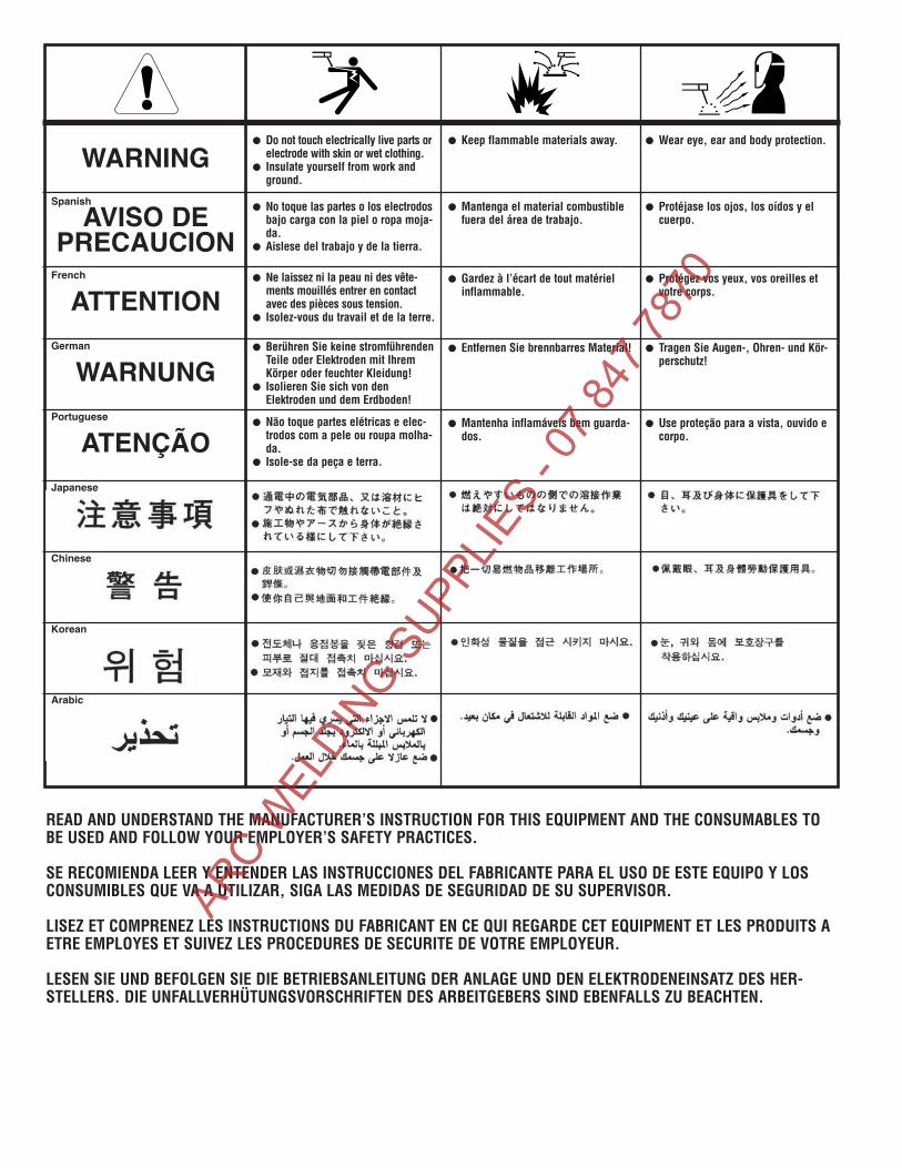
WARNING
AVISO DEPRECAUCION
ATTENTION
WARNUNG
ATENÇÃO
Spanish
French
German
Portuguese
Japanese
Chinese
Korean
Arabic
READ AND UNDERSTAND THE MANUFACTURER’S INSTRUCTION FOR THIS EQUIPMENT AND THE CONSUMABLES TOBE USED AND FOLLOW YOUR EMPLOYER’S SAFETY PRACTICES.
SE RECOMIENDA LEER Y ENTENDER LAS INSTRUCCIONES DEL FABRICANTE PARA EL USO DE ESTE EQUIPO Y LOSCONSUMIBLES QUE VA A UTILIZAR, SIGA LAS MEDIDAS DE SEGURIDAD DE SU SUPERVISOR.
LISEZ ET COMPRENEZ LES INSTRUCTIONS DU FABRICANT EN CE QUI REGARDE CET EQUIPMENT ET LES PRODUITS AETRE EMPLOYES ET SUIVEZ LES PROCEDURES DE SECURITE DE VOTRE EMPLOYEUR.
LESEN SIE UND BEFOLGEN SIE DIE BETRIEBSANLEITUNG DER ANLAGE UND DEN ELEKTRODENEINSATZ DES HER-STELLERS. DIE UNFALLVERHÜTUNGSVORSCHRIFTEN DES ARBEITGEBERS SIND EBENFALLS ZU BEACHTEN.
● Do not touch electrically live parts orelectrode with skin or wet clothing.
● Insulate yourself from work andground.
● No toque las partes o los electrodosbajo carga con la piel o ropa moja-da.
● Aislese del trabajo y de la tierra.
● Ne laissez ni la peau ni des vête-ments mouillés entrer en contactavec des pièces sous tension.
● Isolez-vous du travail et de la terre.
● Berühren Sie keine stromführendenTeile oder Elektroden mit IhremKörper oder feuchter Kleidung!
● Isolieren Sie sich von denElektroden und dem Erdboden!
● Não toque partes elétricas e elec-trodos com a pele ou roupa molha-da.
● Isole-se da peça e terra.
● Keep flammable materials away.
● Mantenga el material combustiblefuera del área de trabajo.
● Gardez à l’écart de tout matérielinflammable.
● Entfernen Sie brennbarres Material!
● Mantenha inflamáveis bem guarda-dos.
● Wear eye, ear and body protection.
● Protéjase los ojos, los oídos y elcuerpo.
● Protégez vos yeux, vos oreilles etvotre corps.
● Tragen Sie Augen-, Ohren- und Kör-perschutz!
● Use proteção para a vista, ouvido ecorpo.
ARC W
ELDIN
G SUPP
LIES
- 07 8
47 78
70

WARNING
AVISO DEPRECAUCION
ATTENTION
WARNUNG
ATENÇÃO
Spanish
French
German
Portuguese
Japanese
Chinese
Korean
Arabic
LEIA E COMPREENDA AS INSTRUÇÕES DO FABRICANTE PARA ESTE EQUIPAMENTO E AS PARTES DE USO, E SIGA ASPRÁTICAS DE SEGURANÇA DO EMPREGADOR.
● Keep your head out of fumes.● Use ventilation or exhaust to
remove fumes from breathing zone.
● Los humos fuera de la zona de res-piración.
● Mantenga la cabeza fuera de loshumos. Utilice ventilación oaspiración para gases.
● Gardez la tête à l’écart des fumées.● Utilisez un ventilateur ou un aspira-
teur pour ôter les fumées des zonesde travail.
● Vermeiden Sie das Einatmen vonSchweibrauch!
● Sorgen Sie für gute Be- undEntlüftung des Arbeitsplatzes!
● Mantenha seu rosto da fumaça.● Use ventilação e exhaustão para
remover fumo da zona respiratória.
● Turn power off before servicing.
● Desconectar el cable de ali-mentación de poder de la máquinaantes de iniciar cualquier servicio.
● Débranchez le courant avant l’entre-tien.
● Strom vor Wartungsarbeitenabschalten! (Netzstrom völlig öff-nen; Maschine anhalten!)
● Não opere com as tampas removidas.● Desligue a corrente antes de fazer
serviço.● Não toque as partes elétricas nuas.
● Do not operate with panel open orguards off.
● No operar con panel abierto oguardas quitadas.
● N’opérez pas avec les panneauxouverts ou avec les dispositifs deprotection enlevés.
● Anlage nie ohne Schutzgehäuseoder Innenschutzverkleidung inBetrieb setzen!
● Mantenha-se afastado das partesmoventes.
● Não opere com os paineis abertosou guardas removidas.
ARC W
ELDIN
G SUPP
LIES
- 07 8
47 78
70

• Sales and Service through Subsidiaries and Distributors Worldwide •
Cleveland, Ohio 44117-1199 U.S.A. TEL: 216.481.8100 FAX: 216.486.1751 WEB SITE: www.lincolnelectric.com
• World's Leader in Welding and Cutting Products •
ARC W
ELDIN
G SUPP
LIES
- 07 8
47 78
70