arc -furnace flicker compensation in ethiopia
TRANSCRIPT
Arc -furnace Flicker Compensation in Ethiopia.
By E. Friedlander, Assefa Telahun and D. J. Young
This article has also appeared in GEC Journal, Vol. 32, No. 1, 1-52, London, 1965. E. Friedlander, Dr. lnf?., M./ .E.E. and D.J. Yung, B.A., Graduate I.E.E., are with the General Electric Company Limited of England. Assefa Telahun, B.Sc. (Eng.), A.M.l.E.E. is Deputy Chief Engineer of the Ethiopian Electric Light and Power Authority.
INTRODUCTION
A previous article has outlined a method developed by GEC for compensating voltage fluctuations caused by electric are furnaces. The first commercial installation based on this principle has now been successfully commissioned in Ethiopia.
A 2.62MV A arc furn ace was connected to the supply system of the Ethiopian Electric Light and Power Authority on June 26, 1962. The voltage fluctuation on a 15kV bus-bar in Addis Ababa, the main consumption centre, was so St!vere that swings down to 14kV and up to 16kV were not uncommon as the furnace current fluctuated from one extreme to the other. Using an ordinary voltmeter, the corresponding figures were 13 and 17kV at the steel plant, about 20 km from Addis Ababa Substation. Complaints were received not only from consumers referring to light flicker but also from radio stations, from the Imperial Ethiopian Air Force - requiring a steady supply for the calibration of precision instruments - as well as from owners of small water pumps and from an important photocopying studio. Flicker was also observed at consumption centres 400 km. away from the steel works.
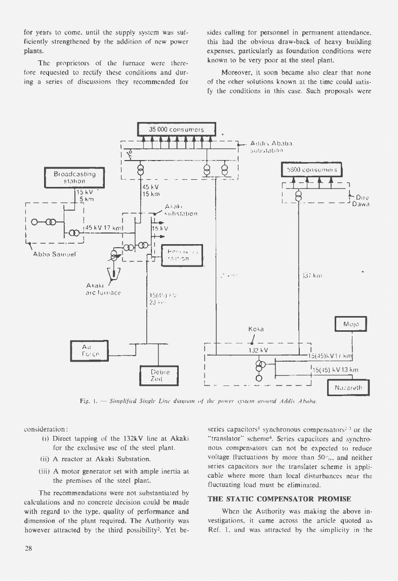
The supply system to which the furnace is connected consists in the main of a hydro plant at Koka, with an insta1led capacity of 3 x 18MV A, feeding 81 km of 132kV line to Addis Ababa and a 337 km line to Dire Dawa. There is a small hydro plant, with an installed capacity of 7MV A, feeding the system at 45kV from Abba Samuel. The single line diagram, fig. 1, shows the main elements of the system and the location of important consumers affected by the operation of the furnace. The system is still relatively weak, and at the time it was decided to install the furnace there were no criteria known to the Authority by which to predict the effects of a furnace of
this size in relation to the capacity of the interconnected system.
A number of trials were made to find out the optimum condition for operating the furnace, with the following results :
(i) To isolate Abba Samuel for the exclusive use of the furnace was found impossible because of difficulties encountered with gates. penstocks, turbine regulators and by-pass valves. During one test the penstock feeding one of the turbines burst. Frequency as well as voltage variations were severe.
(ii) The flicker conditions at consumers' premises were found intolerable when the supply was maintained with one generator in Koka working in parallel with one or more generators in Abba Samuel. Conditions improved slightly when two generators in Koka ran in parallel with Abba Samuel. A 6.25MV A standby steam station in Addis Ababa when put in parallel to the above combination improved conditions still further, but not enough for most consumers.
(iii) The disturbances seemed to be practically independent of the magnitude of the arc furnace load. They were intolerable even when the worst possible fluctuations were prevented by exclusive operation of the furnace on maximum reactance.
POSSIBLE SOLUTIONS EXAMINED
In view of the annoyance caused by the flicker of lighting and in response to a request from the largest broadcasting station in Addis Ababa, the furnace was prevented from operating between 3 p.m. and midnight. Consumers who had to work on and off continuously throughout the 24 hours, however, still suffered. Without a remedy, the operation of the furnace would cause quality of supply to be poor
27
•
for years to come, until the supply system was sufficiently strengthened by the addition of new power plants.
The proprietors of the furnace were therefore requested to rectify these conditions and during a series of discussions they recommended for
35 000 consumers
sides calling for personnel in permanent attendance, this had the obvious draw-back of heavy building expenses, particularly as foundation conditions were known to be very poor at the steel plant.
Moreover, it soon became also clear that none of the other solutions known at the time could satisfy the conditions in this case. Such proposals were
...- - --- •--- •-.._.._.__ - - '1-· Addi<, AbJba . , __ _.__.__......_.__.__...__.____._..,...... ___ , \ sull'.ldt1on
I 'b I I
Broadcasting st\'lt1on
I I '.:1800consur11e1s
L - ·- - J
15 kV -' 51\m r---- ..,
I I
.--
I 45kV17kml I ~- - - -·- _J
Abba Samuer
Akak1 Y1 arc furnace
45 kV 15 km
A~;il-1
· __...., ~ubslilt1on ·
"'t> (' 1\11' I '.I ~, f ,! '·'Jn
15(·1'•) • v 23 ~ 11.
..
Koka ~ ]_
I 132 kV I I 1- '---------.--------15( 45)f..V1 I km
I 115(-l5)kV13km I L _ _ ___ _J
N..i!areth
Fig. I. - Simplified Single Line diagram of the power system around Addis Ababa.
consideration: (i) Direct tapping of the 132kV line at Akaki
for the exclusive use of the steel plant.
(ii) A reactor at Akaki Substation.
(iii) A motor generator set with ample inertia at the premises of the steel plant.
The recommendations were not substantiated by calculations and no concrete decision could be made with regard to the type, quality of performance and dimension of the plant required. The Authority was however attracted by the third possibility2• Yet be-
28
series capacitors1 synchronous compensators2 3 or the "translator" scheme4• Series capacitors and synchronous compensators can not be expected to reduce voltage fluctuations by more than 50%, and neither series capacitors nor the translater scheme is applicable where more than local disturbances near the fluctuating load must be eliminated.
THE STATIC COMPENSATOR PROMISE
When the Authority was making the above investigations, it came across the article quoted as Ref. I. and was attracted by the simplicity in the

operational features of the experimental equipment described. The Authority therefore wrote to GEC (Engineering) Ltd., enclosing all relevant technical information on its supply system and requesting GEC to investigate the possibility of applying the reactor method of compensation to meet the difficulties encountered. It emerged that the static compensator type of equipment described would be somewhat less expensive than, and technically preferable to, the alternative of a motor generator set to which the Authority had referred in its letter of enquiry. On the basis of the information furnished and after a visit to Addis Ababa by GEC engineers, the company was authorised to proceed with the preliminary design and preparation of a cost estimate for the compensating equipment, with due regard to the response of electronic equipment to very rapid voltage changes. In spite of the fact that such equipment had never been produced for practical application heretofore, GEC agreed to guarantee:
(i) that the equipment will confine the volt~ge variations to about one seventh (as obtained from the experimental results) of the fluctuations experienced with the compensator disconnected and
ph
(ii) that the compensated voltage fluctuations will have no effect on the reduction of life and malfunctioning of electronic equipment.
The contract was eventually signed with GEC in February 1963, and the bulk of the equipment was despatched towards the end of the same year. After some delays due to transport problems, it was finally commissioned several months later. It has now been in full operation since July 29, 1964.
THE ARC FURNACE.
The arc furnace is of conventional design. The furnace transformer primary winding has three voltage tappings and may be connected in star or delta, thus making available 6 secondary voltages. A series air-gap reactor was available to limit the short circuit power of the furnace. This reactor had three tappings and a short-circuiting switch.
REQUIREMENTS OF THE COMPENSATOR
The fluctuations could be caused by the furnace
on whichever voltage tapping it was operated, and it was therefore necessary that the compensator should act correctly for all the available furnace voltage tappings. In addition, it was necessary that the com-
I c.
C:i
Fig. 2. - Single-phase diagram of flicker compensator including internal voltage boosting.
29
..

pensator should not detract from the performance of the arc furnace, and that it should be possible to install the compensator with a minimum of interference to normal furnace operation and with a minimum of alteration to the existing high-voltage, control and protection circuits.
It was decided that the most suitable form of compensator satisfying these conditions would be the tapped-reactor/ saturated-reactor scheme, including internal voltage boost correction. The basic scheme (corresponding to fig. 9 of reference 7) is shown in fig. 2. The existing air-gap reactor would be replaced by a new air-gap transformer reactor appropriately rated. The saturated reactor would at the same time be designed to function as an auto transformer in order to restore the furnace voltage, which tends to be reduced by the compensator.
Observations during normal operation of the furnace indicated that the furnace current could swing up to twice its rated value during certain periods of operation. The compensator was therefore designed to cover this range of furnace current swings.
TIIEORY OF OPERATION It is proposed to recall briefly at this point the
theory of the compensator in its simplest form as explained in reference 1. This can best be seen by reference to fig. 3 and 4, which show respectively the characteristic of the saturated reactor and the simplified equivalent circuit of fig. 2. The boosting effect is omitted and the saturated reactor is represented by its apparent content of a generated e.m.f., Vs, with a series reactance, Xs.
Ii'
---
Is Ii ··- lo
Fig. 3. - Voltage/Current Characteristic of saturated reactor.
In fig. 4 the total current taken by the furnace and the saturated reactor is Ii. the furnace current is
30
Vp Fixed-supply-voltage level
v, -------.:.F..:.:.lic:::_::ker· voltage level
_j _ __ _ 11 _ _ 1 1 ..
1 - - - -~J--r----!.4V2 I n
j ___ _
Furnace voltage
h -/3
Fig. 4. - Equivalent circuit of compensator.
..
I3, the bus-bar voltage where flicker is to be eliminated is V1 and the voltage on the bus-bar side of the saturated reactor is V z. The characteristic of the saturated reactor may be expressed approximately by a linear equation
V2=Vs+IsjXs (1)
where Vs is shown in fig. 3. Is is the current through the saturated reactor, and from fig. 4 it follows that
(2) X1 is the reactance of the tapped air-gap reactor
referred to the section through which I1 passes, the tapping ratio being n: 1.
The applied voltage, Vp, at the infinite-bus bar level of the system may be expressed by:
Vp=IdXp+(l1+nl3) · jX1+Vs+(l1-I3) · jXs (3) where Xp is the total supply reactance. This equation can be rewritten
(Vp-Vs)=Id (Xp+X1+Xs) + l3j(nX1-Xs) (4) If the system is tuned to the condition
(5)
then (Vp-Vs)=Iij (Xp+ Xs (1 +n) ! n) (6)

This equation shows that, provided the quantity (Vp-Vs) is constant, the influence of the furnace current I3 on the total current I 1 is eliminated. This is the condition required for the prevention of voltage fluctuation. Although the voltages Vp and Vs are individually constant, they are vector quantities, so that 11 is constant only if there is no phase-swing between Vp and Vs. If 11 is a reactive current, this condition is satisfied. In the range from short-circuit to open-circuit of a furnace, the practical variations in the phase-angles of the two voltages do not in fact impair compensation as is explained in the previous article.
POWER FACTOR CORRECTION AND ABSORPTION OF HARMONICS
The principle of any compensator needed in cases of severe voltage fluctuations penetrating
throughout a widespread power-supply network, requires the loading of the network with reactive power such that the compensator fills in the troughs in reactive power demand of the furnace. The result is that practically the worst - normally only transient - reactive power demand is made continuous during the operation of the furnace. Without power factor correction this would involve a lowering of the average power factor to an extent which would generally be uneconomical. For instance, if the maximum furnace current is twice the rated current normally taken at an average power factor of about 0.85, the perpetuation of this maximum reactive power would reduce the average power factor to about 0.4.
In addition, the use of highly saturated iron involves the generation of harmonic currents which must be prevented from circulating throughout the network. This is possible by internal compensation if the saturated reactor operates in complete 3-phase symmetry. However, the arc furnace will prevent such
Supp1y------t1----iJr-------------------~ • Previous
furnaceO.C.B <useo as main
r---+---f--__. 'supply o.c.~.
/
/,./ /C
II /
11 Existing 1525 kVA
)i furnace 11 reactor
f
/ /A
'1 ,,.,,,,/
· P F C capac1tors,!ano ')atmon1c filters
CompensatP.rl isolators A flnd Bare closeo al)d C is.open
UncompensatP.d : isolalors A and B .:ire open and C is tlosed
Previous reactor by-pass O.C.B . used for off.loao furnace tao·changing
\
To 2·6 M VA. arc furnace transforme1
Fig. 5. - Schcm£' of Connections of Compensator and fumace installation
31
..

symmetrical behaviour by its own erratic arc performance, and to obtain a satisfactory performance
under all conditions the application of harmonic-absorption filters is necessary.
• •
Fig. 6. - Gelleral View of Compensator Equipment. ..
Fig. 7. - The Main Reactor Tanks.
32

Fig. 8. - The frequency Co11rroller.
Fortunately these two requirements for improving the power factor on the one hand, and for absorbing the harmonics of the saturated reactor on the other, are simultaneously satisfied by the installation of harmonic filters tuned to short circuit the bus bar with respect to individual harmonics, because these filters inevitably also produce capacitive reactive power at the fundamental frequency. It was therefore necesary to select the size and number of these filters to satisfy the numerical conditions resulting from the loading of the system with reactive power and saturation harmonics.
However, a third condition has been found to be of importance: it is necessary to absorb the harmonics in such a way that the tuning condition (equation 5), in which Xs is a complex function depending also on the flow of the harmonics, is equally satisfied whether the furnace subjects the system to a symmetrical 3-phase or to an assymmetrical (unbalanced) load. Some of the harmonics, namely those of any order that is divisible by 3, tend to follow different paths for single and 3-phase operation unless special attention is given to their absorption on the
right level. It would, for instance, be inadvisable to short circuit the triplen harmonics by a plain mesh winding applied to the saturated reactors, or to apply the filters straight across the saturated reactors, as is usual for constant voltage transformers. It has been found important to connect the harmonic filters to that part of the system where the voltage is constant, and to guide the triplen harmonics in such a way that they are short-circuited on the same level, irrespective of whether this short circuit is accomplished under symmetrical working conditions by a mesh winding or under assymmetrical conditions by filters. This led to the overall scheme shown in fig. 5.
THE COMPLETE INSTALLATION.
So that the compensator could be easily erected without interfering with normal furnace operation, a system of isolators was provided. These isolators also make it possible in an emergency to operate the furnace through the original air-gap reactor while the compensator is isolated from the supply. lt was also desirable that the arc furnace transformer could be disconnected from the supply without tripping out the compensator for the brief inter-
Fig. 9. - The relay panel.
33
•

;,
J l
Plastic Floor Tiles
* RESISTS ABRASION
* RESIST STRETCHING and LAMINATION
* DAMPS SOUND WAVES
* NOT SLIPPERY
* MADE IN THICKNESSES
OF 1 & 1.5 mm.
* VEINED & MARBLED PATTERNS ·38 COLOURS
* PLASTIC WATER PROOF
* ROLLS FOR ROOF
* PLASTIC MOSAIC TILING FOR BATIQlOOMS etc.
for reliability
specify GER FLEX 34
~f it is
LOUVRI WINDOWS Architects Specify
NACD SUNSASU Sold in 104 Countries
around the world
WHY?
1. Neat Flush Fitting Handle.
2. Weather sealing (Important in Ethiopia).
3. 90° plus opening with modem clean lines.
~· Center pivoted (cannot blow opened or closed).
5. This feature makes cleaning easy.
6. Unobstructed vision but with safe small openings.
7. Simple positive locking device.
THATS WAY
Sole Agents:
VETRERIA (JOMEI~LO
P. O. Box 693 Tel. 11281
ADDIS ABABA

ruptions necessary in the normal furnace operating cycle. For this an additional circuit breaker, connected between the output from the compensator and the furnace transformer, was required. The circuit breaker which had originally served for short-circuiting the air-gap reactor was found to be suitable for this duty, and the furnace circuit breaker was retained in its original position as the main circuit breaker for the whole equipment.
The compensation circuit as shown in fig. 5 is the 3-phase equivalent of the circuit shown in fig. 2. including filters for all odd harmonic frequencies below the 15th harmonic. The suppression of triplen harmonic phase voltages and fluxes requires, of course. a mesh winding. The looping of this mesh over both the saturated and the linear reactors is important for the reasons stated in the previous section.
Fig. 6 shows a general view of the outdoor equipment. The main air-gap and saturated-reactors are housed in 3 separate tanks (one for each phase). This arrangement was chosen in order to comply with transport restrictions. The three tanks are seen on the left. Between these and the capacitor banks on the right is a further tank containing all 18 filter reactors. The cabling between all units and the furnace installation was carried out with polythene-insulated cable. Fig. 7 is a close-up of the 3 main reactor tanks on which the control handles for off-load tap changing gear are seen on the left-hand side. The tap changers serve for on-site adjustment of the compensator.
PROTECTIVE DEVICES
The existing protective devices to the furnace were all, of course. retained.
Frequency protection
With an arrangement of individual absorption filters connected in parallel such as were provided for Akaki, difficulties may be experienced if the system undergoes marked frequency changes. Such a frequency change would shift the relative frequency spectrum of the filters and could present a very high impedance to one o( the higher harmonics, leading to the generation of an undesirable harmonic voltage. The frequency of the Ethiopian power system was controlled by hand at the Koka generating station. and a simple frequency controller had to be developed to obviate any possibility of wide frequency variations occurring without the system control engineer being aware o( them. This controller simulates the action of a human operator by giving control pulses as required to restore the fre-
quency automatically to 50 cycles within ±0.5%. The controller was successfully installed at the Koka generating station. It can operate on any, or all, of the generators.
In spite of this, excessive frequency variations could still occur under transient conditions in the furnace and coincidental load-switching elsewhere on the system. To protect the network and the filters of the compensator, a frequency relay was connected at Akaki to trip out the compensator in case of any excessively large frequency variations. So far no such trip-out has occurred even when experiments were made with only one generator at Koka feeding the network while the furnace was in operation.
Protection of the filters
Protective devices were provided for each phase of each harmonic filter to detect any failure of individual capacitor units. Null-type protection was applied for the 3rd and 5th harmonic filters and series current transformer protection for the remaining filters. Operation of the relevant relays would give a warning to the furnace operator if any small, but not immediately serious, deviation from the designed capacitance values occurred. If a critical change of capacitance should occur the protective devices would trip out the compensator and indicate which filter needed attention.
Protection of the reactors Bucholz gas relays were fitted to the saturated
reactor and filter-choke tanks. In addition, oil temperature thermometers were provided for these tanks to trip out the equipment in the event of overtemperature. A time-delayed (averaging) ammeter was fitted to the saturated reactor in one phase to give an indication and warning if this became overloaded during periods of high voltage with the furnace switched off. All these protective devices were fitted to a relay panel, shown in fig. 9, which was installed in the transformer room at the back of the arc furnace.
ERECTION COMMISSIONING AND TESTING
The equipment was erected and the bus bar alterations and cabling were carried out by Ethiopian personnel directed by a GEC erection engineer.
Extensive experimental instrumentation was taken to site for the purpose of commissioning. This included a six-channel ultra-violet recorder, and a "current metering hook" which has recently been developed by GEC and enabled easy oscilloscope inspection of wave shapes and measurement of current in all cables involved. This hook is shaped rather like a shepherd's crook and may be hooked on to
35
•

Fig. 10. - The metering hook in use.
any single core cable. The output from the hook is fed into an integrating amplifier and the output from the amplifier may be taken to an ameter, an oscilloscope, or other recording device. Fig. 10 shows the erection engineer using the metering hook on the filter circuits, which are easily accessible below the cablebox of the reactor bank.
The integrating amplifier was also useful for revealing another important stress quantity. By using the integrating amplifier with reference to filter currents available through current transformers, it is possible to derive indirectly the wave shapes of the capacitor voltages in the filters. These voltages are of importance as they disclose not only the crest value but also the harmonic power to which the capacitors are subjected. Fig. 11 shows an example of a capacitor voltage, in this case of the 11th harmonic filter, derived in this way.
The effectiveness of the filters under the conditions of maximum saturation of the main reactors is well illustrated by the voltage oscillogram shown in fig. 12. This condition occurs when the furnace is switched off but the compensator is left in operation.
A programme of testing was carried out to check the current loadings in each part of the circuit and to confirm that the overall performance was satisfactory and in agreement with the design.
The only point in which there was a marked deviation from the theoretical performance was in the 7th harmonic filter currents, which were higher than expected with the furnace in operation. This was
36
caused partly by the furnace harmonics and partly by the saturated reactor characteristic being slightly flatter than had been anticipated. Work is in hand to relieve the stressing of this 7th harmonic filter.
PERFORMANCE OF IBE COMPENSATOR IN SERVICE
From the first switching-on of the equipment, it was evident that performance was satisfactory and that the light flicker had practically disappeared, even in the offices and bungalows on the steelworks estate. The extent of elimination of the voltage fluctuations is best summarised in the table.
Fig. 11. - Oscillogram of tire voltage of an eleventh harmonic filter capacitor during furnace operation.
Fig. 12. - Oscillo.i::ram of the bushar voltage with compensator ill service and furnace on open circuit.
Fig. 13. - Oscillogram showing furnace village and current fluctuations without compensation.
Fig. 14. - Osci/logram showing fumace voltage and current fl11ct11at:ons with compensation.
Fig. 15. - Oscillogram showing voltage fluctuations with compensation giving line, saturated-reactor and furnace currents.

PERCENTAGE VOLTAGE FLUCTUATIONS
AT lNSTALLA· TION OF BEFORE AFTER FURNACE COM PEN· COMP EN·
1962 SATION SATION
Addis Ababa 15kV 5 % C 4·8 % c 0·3 % D Akaki 45kV 11'6% c 11·4% c 0·7% D Akaki Furnace 21'5% c 16·2% C, 1 % (very
Abba Samuel 15kV I 12 % M rarely 2t%) M
11·4% c 10·5% c 0·7 % D
C = Worst conceivable condition computed, M = Measured, D = Derived
The actual result obtained is seen to be much better than the value stipulated in the contract. There were, however, occasional larger deviations within about 2 to 3%. These are essentially due to sudden load variations at the furnace producing transient frequency variations. The suppression of voltage fluctuations has been found satisfactory. The reaction of sensitive consumers like the Air Force, the Broadcasting Station and a government receiving station very near the steel plant, has also been positive. The Air Force, in fact, confirmed that the compensation was fully satisfactory.
Conceivable effects of transients had caused some concern before the commissioning of the plant, but to date no occurrences have been observed which could be traced to transients originating from switching the highly saturated reactors. In fact these transients turned out to be only little more severe than those experienced during any switching of transformers.
The restriction imposed on the operating schedule of the arc furnace has become unnecessary, and the proprietors can operate it continuously if they so desire.
Preliminary figures about the specific power consumption per ton of charge indicate the rise which was to be expected in view of the unavoidable losses in the compensator. These are about 4% of the furnace transformer rating. Some additional losses caused by the overloading of the 7th harmonic filter are expected to be reduced when a relief reactor is installed.
The results with respect lo the main performance of the equipment are best demonstrated by the recording shown in fig. 13, 14 and 15. These supp:)rt the information given in the table.
Fig 13 shows the effect of the fluctuating furnace currents during the worst periods of initial melting down. The light-flicker was measured in all three
phases by means of photocells and amplifiers, and includes not only the light output, but also the 100 cf s fluctuation of the light which is normally invisible. This 100 cf s fluctuation explains the broad bands seen in the three voltage traces of the oscillogram. In the uncompensated state, the greatest voltage fluctuation producing visible light-flicker was 12 per cent. The lower 3 traces give the fluctuation of the three furnace currents.
Fig. 14 shows the same recorded quantities but with the compensator in operation. This recording was taken during the first two or three minutes after switching on with cold scrap. During this period, the worst short circuits and asymmetries occur. When analysing the recording one finds that the worst fluctuation has actually reached 2t% at one point. This is an exceptional condition which could have been prevented by running the compensator on a higher saturation level. This did not seem advisable in the interest of keeping harmonics and losses down. Fig. 15 is typical for the bulk of the melting down period during which such exceptional fluctuations rarely occur. Otherwise fig. 15 gives a similar condition to fig. 14, but in this case instead of recording the three furnace currents the lower traces show only one phase of the line current, of the furnace current and of the saturated-reactor current, the last being seen to be subjected to a variation which is complementary to the furnace current. As may be expected, the residual line current is not constant, on account of the power component in the arc current. In spite of this the voltage fluctuations have practically disappeared, because with the chosen adjustment the residual fluctuation of the reactive current minimises the voltage drop due to the power fluctuation.
CONCLUSIONS
The first commercia! installation of an arc furnace flicker compensation plant based on the principle of complementary reactor-current control, through saturated reactors and tapped buffer reactors, has proved highly successful and has fully justified all expectations. This type of compensation is believed to be the only solution available today for dealing with the worst conditions experienced so far: namely, where an excessive fluctuation of reactive current affects the voltage to such an extent in a distribution system over a wide area, that nothing but a total reduction of the reactive power fluctuation to a small fraction of the initial value will satisfy the conditions for an acceptable freedom of light-flicker in the whole of the network.
37
•

Unavoidably, this type of equipment involves an appreciable capital expenditure. However, to see this expenditure in proper perspective, it must be compared with the earning power of the installations involved, as well as with the few other choices open. such as independent power supplies. or different steel producing methods. ln the present case the accepted solution was found to be by far the most desirable way out of a problem which could otherwise have become embarrassing. ·
REFERENCES
38
l. E. Friedlander, "Voltage-flicker compensation with a.c. saturated reactors," G. E. C. Journal of Science and Technology, Vol. 29 No. 2, (1962).
2. Westinghouse Transmission and Distribution Reference Book, 4th edition, 1950, p. 719.
3. B.M. Jones, J.M. Arthur, C.M. Stearns, A .A. Johnson, "10,000kVA series capacitor improves voltage in 6.6kV line supplying large electric arc furnace load." A.l.E.E. transactions (1948) Vol. 67.
4. H.W. Harper, T.R. Macon, A.F. Sedgwick, "Arc furnace corrective equipment using a high value of buffer reactor", A.I .E.E. trans. 76 (part II) May 1957.
5. C. Concordia, L.G. Levoy, C.H. Thomas, "Selection of buffer reactors and synchronous Condensers on power systems supplying arc furnace loads," A.I.E.E. Transact. Vol. 76 pt. II. 1957.
6. R.O. Askey, "Voltage translator scheme cuts light flicker due to welders", Electrical World Jan. 6, 1945, p. 63.
7. G.F.L. Dixon, E. Friedlander, F. Seddon, D.J. Young, "Static shunt compensation for voltage flicker suppression", paper No. 7, "I.E.E. Symposium on Transient, Fluctuating and Distorting Loads and their Effect on Power Systems and Communications", Feb. 1963. Conference Report Series No. 8 (1964), Abnormal loads on power systems.
y ARC en CIEL II OIL PAINT IN ALL COLOURS
ETOILE de MER II SPECIAL OIL PAINTS
FOR TROPICAL USE
ISOLORY II PLASTIC EMULSION PAINT
OF SUPERIOR QUALITY COMPLETELY W·ASHABLE
LORYLUX II AS ABOVE
BUT PERFUMED
Sole Agent for Ethiopia
MAURICE GHALEB P. 0 . Box 55 Phone 14925
ADDIS ABABA