ar-b1665 socket 370 pentium iii all -in-one ebx board with ... · 1.1 specifications cpu: socket...
TRANSCRIPT

AR-B1665 User’s Guide
AR-B1665
Socket 370 Pentium III All -In-One EBX Board with Audio, LAN, CRT/LCD, and Mini-PCI
User’ s Guide
Edition: 1.0 Book Number: AR-B1665-04.0115
1

AR-B1665 User’s Guide
Table of Contents 0. PREFACE…………………………………………………………………………………………………………………………3
0.1 COPYRIGHT NOTICE AND DISCLAIMER.....................................................................................................................................3 0.2 WELCOME TO THE AR-B1665 CPU BOARD................................................................................................................................3 0.3 BEFORE YOU USE THIS GUIDE...................................................................................................................................................3 0.4 RETURNING YOUR BOARD FOR SERVICE.................................................................................................................................3 0.5 TECHNICAL SUPPORT AND USER COMMENTS ........................................................................................................................3 0.6 STATIC ELECTRICITY PRECAUTIONS ........................................................................................................................................4
1. INTRODUCTION.......................................................................................................................................................... 5 1.1 SPECIFICATIONS...........................................................................................................................................................................6 1.2 PACKING LIST................................................................................................................................................................................6
2. INSTALLATION........................................................................................................................................................... 7 2.1 AR-B1665'S LAYOUT .....................................................................................................................................................................7 2.2 INSTALLING THE CPU...................................................................................................................................................................8 2.3 INSTALLING THE MEMORY (DIMM) .............................................................................................................................................9 2.4 BATTERY JUMPER (SJ2)...............................................................................................................................................................9
3. CONNECTION........................................................................................................................................................... 10 3.1 12-PIN AUDIO CONNECTOR (AUDIO) ........................................................................................................................................10 3.2 HARD DISK (IDE) CONNECTOR (IDE0, IDE1) ............................................................................................................................10 3.3 PARALLEL PORT CONNECTOR 1 (LPT) ....................................................................................................................................11 3.4 SERIAL PORTS ............................................................................................................................................................................12 3.5 SERIAL PORT CONNECTOR (COM1, COM2, COM4)................................................................................................................12 3.6 SERIAL PORT CONNECTOR (COM3).........................................................................................................................................12 3.7 RS-485 TERMINATOR SELECT (SPJ2).......................................................................................................................................12 3.8 RS-485 HEADER (SPJ1) ..............................................................................................................................................................12 3.9 TOUCH SCREEN CONNECTOR (TSC) .......................................................................................................................................13 3.10 EXTERNAL KEYBOARD / MOUSE CONNECTOR (KB/MS) .....................................................................................................13 3.11 USB 2.0 CONNECTOR (USB1, USB2, USB3) ...........................................................................................................................13 3.12 INFRARED CONNECTOR (IR) ...................................................................................................................................................13 3.13 CPU FAN POWER CONNECTOR (FAN1, FAN2) ......................................................................................................................13 3.14 ETHERNET LAN CONNECTOR (LAN).......................................................................................................................................14 3.15 CRT CONNECTOR (CRT) ..........................................................................................................................................................14 3.16 FLOPPY PORT CONNECTOR (FDD) ........................................................................................................................................14 3.17 GPIO CONNECTOR (GPIO) .......................................................................................................................................................14 3.18 ATX POWER CONNECTOR (ATX) ............................................................................................................................................16 3.19 LCD CONNECTOR ( LCD)..........................................................................................................................................................16 3.20 LCD SELECT (NJ1).....................................................................................................................................................................16 3.21 VOLTAGE SELECT (VJP1).........................................................................................................................................................16 3.22 PANEL CONNECTOR (PANEL) .................................................................................................................................................17 3.23 PCI SLOT (PCI 1)........................................................................................................................................................................17 3.24 MINI PCI SLOT (MPCI 2) ............................................................................................................................................................17 3.25 PCI SELECT (PJ1) ......................................................................................................................................................................17 3.26 CPU SETTING SYSTEM BUS CLOCK (CKSW1) ......................................................................................................................17 3.27 CD IN CONNECTOR (CDIN) ......................................................................................................................................................17 3.28 DDR SDRAM SOCKET 184 PIN.................................................................................................................................................17 3.29 DVI/TV .........................................................................................................................................................................................17
4. WATCHDOG TIMER ................................................................................................................................................. 18 4.1 WATCHDOG TIMER SETTING ....................................................................................................................................................18
5. BIOS CONSOLE........................................................................................................................................................ 19 5.1 BIOS SETUP OVERVIEW.............................................................................................................................................................19 5.2 STANDARD CMOS SETUP..........................................................................................................................錯誤! 尚未定義書籤。 5.3 ADVANCED CMOS SETUP..........................................................................................................................................................20 5.4 ADVANCED CHIPSET SETUP.....................................................................................................................................................22 5.5 POWER MANAGEMENT ..............................................................................................................................................................23 5.6 PCI/PLUG AND PLAY...................................................................................................................................................................24 5.7 PERIPHERAL SETUP...................................................................................................................................................................25 5.8 HARDWARE MONITOR SETUP...................................................................................................................................................26 5.8 AUTO-DETECT HARD DISKS......................................................................................................................................................27 5.9 PASSWORD SETTING.................................................................................................................................................................27 5.10 LOAD DEFAULT SETTING.........................................................................................................................................................27
5.10.1 Auto Configuration with Optimal Setting..............................................................................................................................27 5.11 BIOS EXIT ...................................................................................................................................................................................27 5.12 BIOS UPDATE ............................................................................................................................................................................28
APPENDIX A. ADDRESS MAPPING............................................................................................................................ 29 APPENDIX B. INTERRUPT REQUEST (IRQ)............................................................................................................... 30
2
AR-B1665 User’s Guide
0. PREFACE
0.1 COPYRIGHT NOTICE AND DISCLAIMER This document is copyrighted, 2002, by Acrosser Technology Co., Ltd. All rights are reserved. No part of this manual may be reproduced, copied, transcribed, stored in a retrieval system, or translated into any language or computer language in any form or by any means, such as electronic, mechanical, magnetic, optical, chemical, manual or other means without the prior written permission or original manufacturer. Acrosser Technology assumes no responsibility or warranty with respect to the content in this manual and specifically disclaims any implied warranty of merchantability or fitness for any particular purpose. Furthermore, Acrosser Technology reserves the right to make improvements to the products described in this manual at any times without notice. Such revisions will be posted on the Internet ( )WWW.ACROSSER.COM as soon as possible. Possession, use, or copy of the software described in this publication is authorized only pursuant to valid written license from Acrosser or an authorized sub licensor. ACKNOWLEDGEMENTS Acrosser, AMI, IBM PC/AT, Windows, MS-DOS…are registered trademarks. All other trademarks and registered trademarks are the property of their respective owners.
0.2 WELCOME TO THE AR-B1665 CPU BOARD This guide introduces the Acrosser AR-B1665 CPU Board. Use information provided in this manual describes this card’s functions and features. It also helps you start, set up and operate your AR-B1665. General system information can also be found in this publication. Please refer to the chapter introduction if you have not already installed this board. Check the packing list before you install and make sure the accessories are completely included.
0.3 BEFORE YOU USE THIS GUIDE Please refer to the Chapter 1, “Introduction” in this guide, if you have not already installed this AR-B1665. Check the packing list before you install and make sure the accessories are completely included. AR-B1665 CD provides the newest information regarding the CPU card. Please refer to the files of the enclosed utility CD. It contains the modification and hardware & software information, and adding the description or modification of product function after manual printed.
0.4 RETURNING YOUR BOARD FOR SERVICE If your board requires any services, contact the distributor or sales representative from whom you purchased the product for service information. If you need to ship your board to us for service, be sure it is packed in a protective carton. We recommend that you keep the original shipping container for this purpose. You can help assure efficient servicing for your product by following these guidelines: 1. Include your name, address, daytime telephone, facsimile number and E-mail. 2. A description of the system configuration and/or software at the time of malfunction. 3. A brief description of the problem occurred.
0.5 TECHNICAL SUPPORT AND USER COMMENTS Users comments are always welcome as they assist us in improving the quality of our products and the readability of our publications. They create a very important part of the input used for product enhancement and revision. We may use and distribute any of the information you provide in any way appropriate without incurring any obligation. You may, of course, continue to use the information you provide. If you have any suggestions for improving particular sections or if you find any errors on it, please send your comments to Acrosser Technology Co., Ltd. or your local sales representative and indicate the manual title and book number. Internet electronic mailto:[email protected] [email protected]
3

AR-B1665 User’s Guide
0.6 STATIC ELECTRICITY PRECAUTIONS
Before removing the board from its anti-static bag, read this section about static electricity precautions. Static electricity is a constant danger to computer systems. The charge that can build up in your body may be more than sufficient to damage integrated circuits on any PC board. It is, therefore, important to observe basic precautions whenever you use or handle computer components. Although areas with humid climates are much less prone to static build-up, it is always best to safeguard against accidents that may result in expensive repairs. The following measures should be sufficient to protect your equipment from static discharge: Touch a grounded metal object to discharge the static electricity in your body (or ideally, wear a grounded wrist strap). When unpacking and handling the board or other system components, place all materials on an anti-static surface. Be careful not to touch the components on the board, especially the “golden finger” connectors on the bottom of the board.
4

AR-B1665 User’s Guide
1. INTRODUCTION Welcome to the AR-B1665 Single Embedded Board Computer in EBX form factor board. AR-B1665 provides a flexible system that allows users to choose the performance of system as their wish. AR-B1665 supports Socket 370 Pentium III (Coppermine and Tualatin), Intel Celeron, Via C3 processors with speed up to 1.26G with FSB 100/133 /66 MHz. AR-B1665 is equipped with high performance VIA ® advanced chipset CLE266 version CD (North Bridge VT8623-CE plus South Bridge VT8235-CD). This product is designed for the system manufacturers, integrators, or VARs that want to provide all the performance, reliability, and quality at a reasonable price. AR-B1665 provides one 184 pin DIMM socket that supports up to 1 GB DDR266/DDR200 (PC2100/PC1600) Double Data Rate(DDR) SDRAM. The DDR interface allows zero wait state bursting between the DRAM and the data buffer at 133/100 MHz. AR-B1665 also provides on board VGA(CRT and 24 bit LCD),one LAN that support 10/100M Base-Tx, AC97 Codec for Audio with an optional small board amplifier(AR-B9425) and six USB 2.0 port with poly fuse protection. The most eyes popping characteristic of AR-B1665 is its graphic/video accelerator that is integrated into CLE266 North Bridge. It provides internal AGP 4x performance along with 128-bit 2D Graphics Accelerator, 128-bit 3D Graphics Accelerator and DVD playback with MPEG-2 base. Based on all of the features above, AR-B1665 is an ideal solution for consumers that are looking for high speed performances with flexible option for further upgrade at a reasonable price.
Socket 370
SMA North BridgeVT8623
Host Bus(FSB)
South BridgeVT8235
V-Link Bus
(DDR)Main Memory
CPU
DDR 266
1 DIMM Socket
Primary(40 pins) and2 x IDE
LPC Super I/O
VT1211
LPC Bus
PortParallel
Serial Port
Keyboard&Mouse
Secondary(44 pins)
6 x USB 2.0
VT1616PCI Bus
AC'97 Audio Codec
CRT
TFT LCD
and HWM
PM control
Fast Ethernet
W83783
1 mini PCI
1 PCI slot
LPC ROM
COM Port x 4
X-Bus
33 MHz
66 MHzDVI Flat Panel
66/100/133 MHz
100/133 MHz
TTL
RGB
DVI
VT6103 10/100 MHz LAN
External SpeakerHWM
DiskFloppy
GPIO
IR
5

AR-B1665 User’s Guide
1.1 SPECIFICATIONS CPU: Socket 370(Pentium III, Intel Celeron, Via C3, Pentium III Tualatin) DMA channels: 7 Interrupt levels: 15 Chipset: VIA ® CLE266 ( VT8623 Integrated 2D ,3D, and MPEG-2 graphics accelerator and VT8235) RAM memory: Provide one 184 pin DDR SDRAM DIMM socket. The memory capability is up to 1GB. VGA Controller: Embedded VGA controller, Screen Resolution: up to True Color (32 bit)1280x1024 Display Interface: CRT –2x5x2.00mm pin-header connector
LCD – for 24 bit TFT LCD Panel, 2x22x2.00mm pin-header connector Ultra ATA/33/66/100 IDE Interface: Two PCI Enhance IDE channel. The south bridge VT8235 supports
Ultra ATA/33/66/100/133 IDE interface. To support Ultra ATA66/100/133 Hard disk, a specified cable(80-conductor ribbon cable) must be available.
Floppy disk drive interface: 2.88 MB, 1.44MB, 1.2MB, 720KB, or 360KB floppy disk drive. Series ports: Four high-speed 16550 compatible UARTs ports with 16-byte send/receive FIFOs
COM1,COM2,COM4: On-board one 2x5x2.54mm Box-Header connector. Only RS232. COM3: On-board one 2x5x2.54mm Box-Header connector. Share with RS-485. Parallel Port: one IEEE1284 compatible Bi-directional ports IrDA port: Supports IrDA (HPSIR) and ASK (Amplitude Shift Keyed)-IR port multiplexed on COM2. USB port: Support six USB 2.0 compatible ports. Audio: Onboard AC’97 Codec, Supports two channel Left/Right Line IN/OUT, and Left/Right speaker out,
MIC IN, CD IN. Watchdog timer: Software programmable 1~60sec. On board Integrated Fast Ethernet : IEEE 802.3u Auto-Negotiation support for 10BASE-T/100BASE-TX
standard. Fast back-to-back transmission support with minimum interframe spacing.Connected to your LAN through RJ45 connector. Support WOL(Wake On LAN).
Keyboard Connector & PS/2 Mouse: Connector on-board Power Consumption: +5VSB @0.3A, +5V@5A (Max), [email protected] (Max), [email protected](Max) Operating Temperature: 0° ~ 60℃ (CPU needs Cooling Fan)
1.2 PACKING LIST
In addition to this User's Manual, the AR-B1665 package includes the following items: The quick setup manual 1 AR-B1665 CPU board 1 Hard disk drive adapter cable for 3.5” hard disk 1 Hard disk drive adapter cable for 2.5” hard disk 1 Floppy disk drive adapter cable 1 Software utility CD 1 Parallel Port interface cable 2 RS-232 and 1 PS/2 Mouse & Keyboard interface cable mounted on bracket
6

AR-B1665 User’s Guide
2. INSTALLATION This chapter describes how to install the AR-B1665. At first, the layout of AR-B1665 is shown, and the unpacking information that you should be careful is described. The following lists the jumpers and switches setting for the AR-B1665’s configuration.
2.1 AR-B1665'S LAYOUT
7

AR-B1665 User’s Guide
2.2 INSTALLING THE CPU The AR-B1665 Embedded Board supports a Socket 370 processor socket for Intel Pentium III (FC-PGA/FC-PGA2) and Celeron processors. The Board uses a CPU socket called Socket 370 for easy CPU installation. The CPU should always have a Heat Sink and a cooling fan attached to prevent overheating. CPU Installation Procedures : 1. Pull the lever sideways away form the socket. Then, raise the lever up to a 90-degree angle.
2. Look for the gold arrow. The gold arrow should point towards the end of lever. The CPU will only fit
in the correct orientation.
3. Hold the CPU down firmly, and then close the lever to complete the installation.
NOTE: Ensure that the CPU heat sink and the CPU top surface are in total contact to avoid CPU overheating problem that would cause your system to hang or be unstable.
8

AR-B1665 User’s Guide
2.3 INSTALLING THE MEMORY (DIMM)
The AR-B1665 Embedded Board supports one 168-pin DIMM socket for a maximum total memory of 512MB in SDRAM type. The memory module capacities supported are 64MB, 128MB, 256MB, and 512MB.
Installing and Removing DIMMs To install the DIMM, locate the memory slot on the Embedded Board and perform the following steps: Hold the DIMM so that the two keys of the DIMM align with those on the memory slot. Gently push the DIMM in an upright position until the clips of the slot close to hold the DIMM in place when the DIMM touches the bottom of the slot. To remove the DIMM, press the clips with both hands.
DIMM
Lock Lock
Lock Lock
Top View of DIMM Socket 2.4 BATTERY JUMPER (SJ2)
1
2
3
1-2: ON-BOARD BATTERY (Factory Preset)
2-3: CLEAR CMOS
Factory Preset
9

AR-B1665 User’s Guide
3. CONNECTION This chapter describes how to connect peripherals, switches and indicators to the AR-B1665 board.
3.1 AUDIO CONNECTOR (AUDIO)
2 12
1 11
3.2 HARD DISK (IDE) CONNECTOR (IDE0, IDE1) • 40-Pin hard Disk Connector (IDE0) A 40-pin header type connector (IDE0) is provided to interface with up to two embedded hard disk drives (IDE AT bus). This interface, through a 40-pin cable, allows the user to connect up to two drives in a “daisy chain” fashion. To enable or disable the hard disk controller, please use the BIOS Setup program, which is explained further in chapter 5. The following table illustrates the pin assignments of the hard disk drive’s 40-pin connector.
1 39
2 40
PIN SIGNAL PIN SIGNAL 1 LINEOUTR 2 LINEOUTL 3 GND 4 GND 5 LINEINR 6 LINEINL 7 GND 8 GND 9 MIC 10 BIAS 11 GND 12 +12V
Pin Signal Pin Signal 1 -RESET 2 GROUND 3 DATA 7 4 DATA 8 5 DATA 6 6 DATA 9 7 DATA 5 8 DATA 10 9 DATA 4 10 DATA 11 11 DATA 3 12 DATA 12 13 DATA 2 14 DATA 13 15 DATA 1 16 DATA 14 17 DATA 0 18 DATA 15 19 GROUND 20 N.C 21 PDDREQ 22 GROUND 23 -PDIOW 24 GROUND 25 -PDIOR 26 GROUND 27 PIORDY 28 GROUND 29 -PDDACK 30 GROUND 31 IRQ14 32 N.C 33 PDA1 34 PD66/100 35 PDA0 36 PDA2 37 -PDCS1 38 -PDCS3 39 HLED1 40 GROUND
10
AR-B1665 User’s Guide
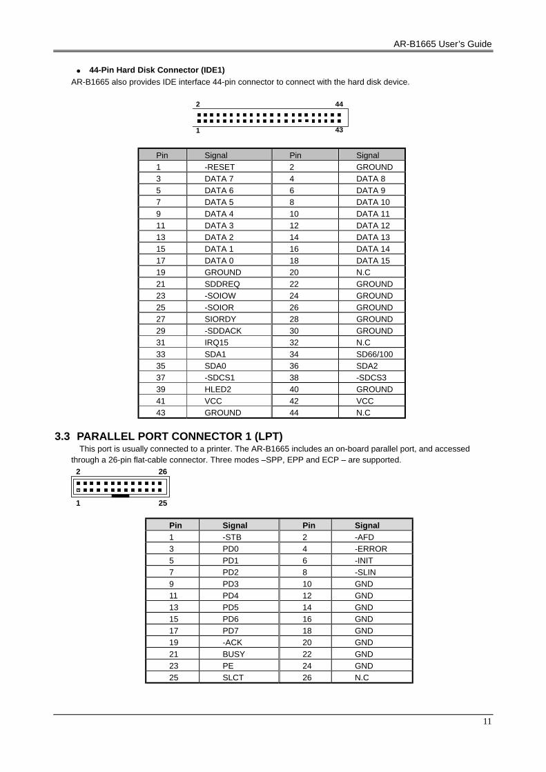
• 44-Pin Hard Disk Connector (IDE1) AR-B1665 also provides IDE interface 44-pin connector to connect with the hard disk device.
43
44
1
2
Pin Signal Pin Signal 1 -RESET 2 GROUND 3 DATA 7 4 DATA 8 5 DATA 6 6 DATA 9 7 DATA 5 8 DATA 10 9 DATA 4 10 DATA 11 11 DATA 3 12 DATA 12 13 DATA 2 14 DATA 13 15 DATA 1 16 DATA 14 17 DATA 0 18 DATA 15 19 GROUND 20 N.C 21 SDDREQ 22 GROUND 23 -SOIOW 24 GROUND 25 -SOIOR 26 GROUND 27 SIORDY 28 GROUND 29 -SDDACK 30 GROUND 31 IRQ15 32 N.C 33 SDA1 34 SD66/100 35 SDA0 36 SDA2 37 -SDCS1 38 -SDCS3 39 HLED2 40 GROUND 41 VCC 42 VCC 43 GROUND 44 N.C
3.3 PARALLEL PORT CONNECTOR 1 (LPT)
This port is usually connected to a printer. The AR-B1665 includes an on-board parallel port, and accessed through a 26-pin flat-cable connector. Three modes –SPP, EPP and ECP – are supported.
1 25
2 26
Pin Signal Pin Signal 1 -STB 2 -AFD 3 PD0 4 -ERROR 5 PD1 6 -INIT 7 PD2 8 -SLIN 9 PD3 10 GND 11 PD4 12 GND 13 PD5 14 GND 15 PD6 16 GND 17 PD7 18 GND 19 -ACK 20 GND 21 BUSY 22 GND 23 PE 24 GND 25 SLCT 26 N.C
11
AR-B1665 User’s Guide
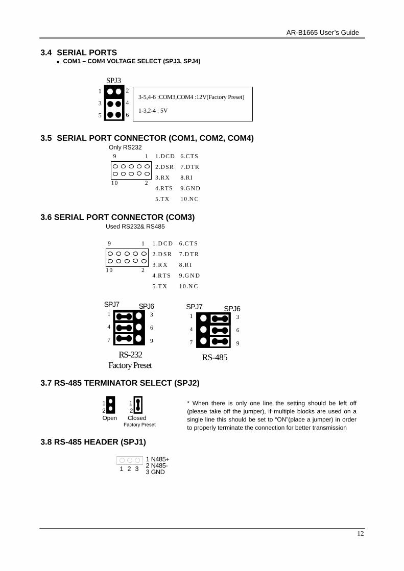
3.4 SERIAL PORTS • COM1 – COM4 VOLTAGE SELECT (SPJ3, SPJ4)
1
3
5
2
4
6
SPJ3
3-5,4-6 :COM3,COM4 :12V(Factory Preset)
1-3,2-4 : 5V
3.5 SERIAL PORT CONNECTOR (COM1, COM2, COM4) Only RS232
1
2
9
10
1.D CD
2.D SR
3.RX
4.RTS
6.CTS
7.D TR
9.G N D
8.RI
5.TX 10.N C
3.6 SERIAL PORT CONNECTOR (COM3) Used RS232& RS485
1
2
9
1 0
1 .D C D
2 .D S R
3 .R X
4 .R T S
6 .C T S
7 .D T R
9 .G N D
8 .R I
5 .T X 1 0 .N C
SPJ7 1
4
7
3
6
9
RS-232
SPJ6
Factory Preset
SPJ7 1
4
7
3
6
9
RS-485
SPJ6
3.7 RS-485 TERMINATOR SELECT (SPJ2)
Open Factory Preset
1 2
1 2
Closed
3.8 RS-485 HEADER (SPJ1)
1 2 3
1 N485+ 2 N485- 3 GND
* When there is only one line the setting should be left off(please take off the jumper), if multiple blocks are used on asingle line this should be set to “ON”(place a jumper) in orderto properly terminate the connection for better transmission
12

AR-B1665 User’s Guide
3.9 TOUCH SCREEN CONNECTOR (TSC)
1 2 3
1 RXDF 2 TXDF 3 GND
3.10 EXTERNAL KEYBOARD / MOUSE CONNECTOR (KB/MS)
The AR-B1665 provides 6-PIN JST Header and 6-PIN MINI-DIN keyboard/mouse connector.
1 6
1.MOUSE DATA
2.KB DATA
3.GND
4.VCC
5.MOUSE CLOCK
6.KB CLOCK 3.11 USB 2.0 CONNECTOR (USB1, USB2, USB3)
1 7
2 8 1.VCC
3.DATA1-
5.DATA1+
7.GND
2.GND
4.DATA2+
6.DATA2-
8.VCC
3.12 INFRARED CONNECTOR (IR) The AR-B1665 built-in IrDA port which support Serial Infrared (SIR) or Amplitude Shift Keyed IR (ASKIR) interface. When use the IrDA port have to set SIR or ASKIR model in the BIOS’s Peripheral Setup’s COM 2. Then the normal RS-232 COM 2 will be disabled.
1 5
2.NC
1. VCC
3.IR DATA RECEIVER
4.GND
5. IR DATA TRANSFER
3.13 CPU FAN POWER CONNECTOR (FAN1, FAN2)
The AR-B1665 provides CPU cooling Fan connector. CPU connectors can supply 12V/500mA to the cooling fan.
2 541 3
1. GND
2. +12V
3. SENSE
13

AR-B1665 User’s Guide
3.14 ETHERNET LAN CONNECTOR (LAN) It is able to collocate with AR-B9450B (optional)
1 9
2 10
PIN SIGNAL PIN SIGNAL
1 LED1+ 2 LED1- 3 RX+ 4 RX- 5 LED2- 6 GROUND 7 LED2+ 8 GROUND 9 TX+ 10 TX-
3.15 CRT CONNECTOR (CRT)
AR-B1665 built-in 15-pin VGA connector directly to your CRT monitor.
1 9
2 10 1.RED
3.GREEN
5.BLUE
7.VSYNC
9.HSYNC
2.GND
6.GND
8.SPCLK
10.SPD
4.GND
3.16 FLOPPY PORT CONNECTOR (FDD)
The AR-B1665 provides a 34-pin header type connector for supporting up to two floppy disk drives. To enable or disable the floppy disk controller, please use the BIOS Setup program.
33
34
1
2
PIN Signal PIN Signal 1-33(odd) GROUND 18 DIRECTION
2 DRVEN 0 20 -STEP 4 N.C. 22 -WRITE DATA 6 N.C. 24 -WRITE GATE 8 -INDEX 26 -TRACK 0
10 -MOTOR ENABLE A 28 -WRITE PROTECT 12 -DRIVE SELECT B 30 -READ DATA 14 -DRIVE SELECT A 32 -SIDE 1 SELECT 16 -MOTOR ENABLE B 34 DISK CHANGE
3.17 GPIO CONNECTOR (GPIO)
10
9
2
1
1.GPIO1 3.GPIO3 5.GPIO5 7.GPIO7
2.GPIO2 4.GPIO4 6.GPIO6
9.GND 8.GPIO8 10.VCC
14

AR-B1665 User’s Guide
Users could test GPIO function under ‘Debug’ program as follow:
GPO Example: o 4e 87
;Extended Functions Enable Register
o 4e 87 ;Extended Functions Enable Register o 4e 29 ;select CR29 o 4f 80 ;(Define the PINs as GPIO or Game Port 1)
"80" Pin121 ~ 128 set as GPIO o 4e 07 ;EFIR=EFER (Extended Functions Index Register)
point to Logical Device Number Reg. o 4f 07 ;EFDR=EFIR+1 (select logical device 7,GPIO in logical device 7 ) o 4e 30 ;select CR30 (Active or inactive) o 4f 01 ;set 01 (Active) ,00 (inactive) o 4e f0 ;select CRF0 (Set the PINs be GPO or GPI Function) o 4f 00 ;set the PINs be GPO o 4e f2 ;select CRF2 (Output High / Low) o 4f 00 ;set the PINs be all Low Level (FF=all High Level) o 4e f1 ;select CRF1
o 4f 07 ;set the output to be 07
o 4e aa ;exit EFER
q ;Quit debug
GPI Example: o 4e 87
;Extended Functions Enable Register
o 4e 87 ;Extended Functions Enable Register o 4e 29 ;select CR29 o 4f 80
;(Define the PINs as GPIO or Game Port 1) "80" Pin121 ~ 128 set as GPIO
o 4e 07
;EFIR=EFER (Extended Functions Index Register) point to Logical Device Number Reg.
o 4f 07 ;EFDR=EFIR+1 (select logical device 7,GPIO in logical device 7 ) o 4e 30 ;select CR30 (Active or inactive) o 4f 01 ;set 01 (Active) ,00 (inactive) o 4e f0 ;select CRF0 (Set the PINs be GPO or GPI Function) o 4f ff ;set the PINs be GPI o 4e f1 ;select CRF1 (Set the PINs be Read only) i 4f ;Show the PINs Value q ;Quit debug
15

AR-B1665 User’s Guide
3.18 ATX POWER CONNECTOR (ATX)
10
20 11
1
2. 3.3V
3. GND
4. 5V
5. GND
6. 5V
7. GND
8. PW-OK
1. 3.3V
9. 5VSB
10. 12V
11. 3.3V
12. -12V
13 GND
14 PS-ON
15. GND
17. GND
16. GND
18. –5V
19. 5V
20 5V 3.19 LCD CONNECTOR ( LCD)
24-Bits LCD PANEL CONNECTOR (LCD)
43
44
1
2
PIN Signal PIN Signal PIN Signal 1 GND 16 G0 31 R3 2 SFCLK 17 G1 32 R4 3 GND 18 G2 33 R5 4 HSYNC 19 G3 34 GND 5 VSYNC 20 GND 35 LCDVCC 6 GND 21 G4 36 LCDVCC 7 B0 22 G5 37 +12V 8 B1 23 G6 38 +12V 9 B2 24 G7 39 GND 10 B3 25 (PD21) 40 GND 11 B4 26 (PD20) 41 DE 12 B5 27 GND 42 ENBLT 13 GND 28 R0 43 GND 14 B6 29 R1 44 ENVDD 15 B7 30 R2
3.20 LCD SELECT (NJ1)
1: LCD (Factory Preset)
0: DVI
Factory Preset
3.21 VOLTAGE SELECT (VJP1)
LCD
1
2
3
1-2: 5V (Factory Preset)
2-3: 3.3V
Factory Preset
16

AR-B1665 User’s Guide
3.22 PANEL CONNECTOR (PANEL)
1 9
2 1 0
POWER BUTTON POWER LED 1. VCC 3. PLED
HARD DISK LED 2. VCC 4. HD-LED
5. GND 6. PWRBTN
RESET BUTTON
9. GND 10. RSTSW
3.23 PCI SLOT (PCI 1) 3.24 MINI PCI SLOT (MPCI 2) 3.25 PCI SELECT (PJ1)
3
2
1
2-3 When riser card is applied,
Please set 2-3 close
1-2 Support one PCI card (Factory Preset)
Factory Preset 3.26 CPU SETTING SYSTEM BUS CLOCK (CKSW1)
OFF
1 2
1 2 CPU OFF OFF 133 OFF ON 100 ON ON 66
3.27 CD IN CONNECTOR (CDIN)
1 2 3 4 2.GN D
1.CD INL
3.CD INR
4.NC
3.28 DDR SDRAM SOCKET 184 PIN (DIMM) 3.29 DVI/TV
1 25
2 26
Optional (For Future Application)
17

AR-B1665 User’s Guide
4. WATCHDOG TIMER This section describes the use of Watchdog Timer. AR-B1665 is equipped with a programmable time-out period watchdog timer that enable user to reset the system after a time out occur. Users can use simple program to enable the watchdog timer, and program the timer in range of seconds or minutes, with maximum 255 seconds/minutes. Once you enable the watchdog timer, the program will start the count down and when counting down to zero the system will generate a reset signal to reset the system.
4.1 WATCHDOG TIMER SETTING The watchdog timer is a circuit that maybe be used from your program software to detect crash or hang up.
The Watchdog timer is automatically disabled after reset. Once you enabled the watchdog timer, your program should trigger the watchdog timer every time before it times out. After you trigger the watchdog timer, the timer will be set to zero and start to count again. If your program fails to trigger the watchdog timer before times out, it will generate a reset pulse to reset the system . Please refer to the following table in order to properly program Watchdog function
Users could test watchdog function under ‘Debug’ program as follows:
C:>debug o 4e 87
;Extended Functions Enable Register
o 4e 87 ;Extended Functions Enable Register o 4e 07 ;EFIR=EFER (Extended Functions Index Register)
point to Logical Device Number Reg. o 4f 08 ;EFDR=EFIR+1 (select logical device 8, Watchdog ) o 4e f3 ;select register F3(to select Watchdog count mode ;seconds or
minutes) o 4f 05 ;write 05 to CRF3(for minutes) ,default is 01(second) o 4e f4 ;select CRF4 (to set Watchdog Timer Value) o 4f 02 ;set the Watchdog timer to 2 minutes. (00 to disable, max FF) o 4e aa ;exit EFER
q ;Quit debug
18
AR-B1665 User’s Guide
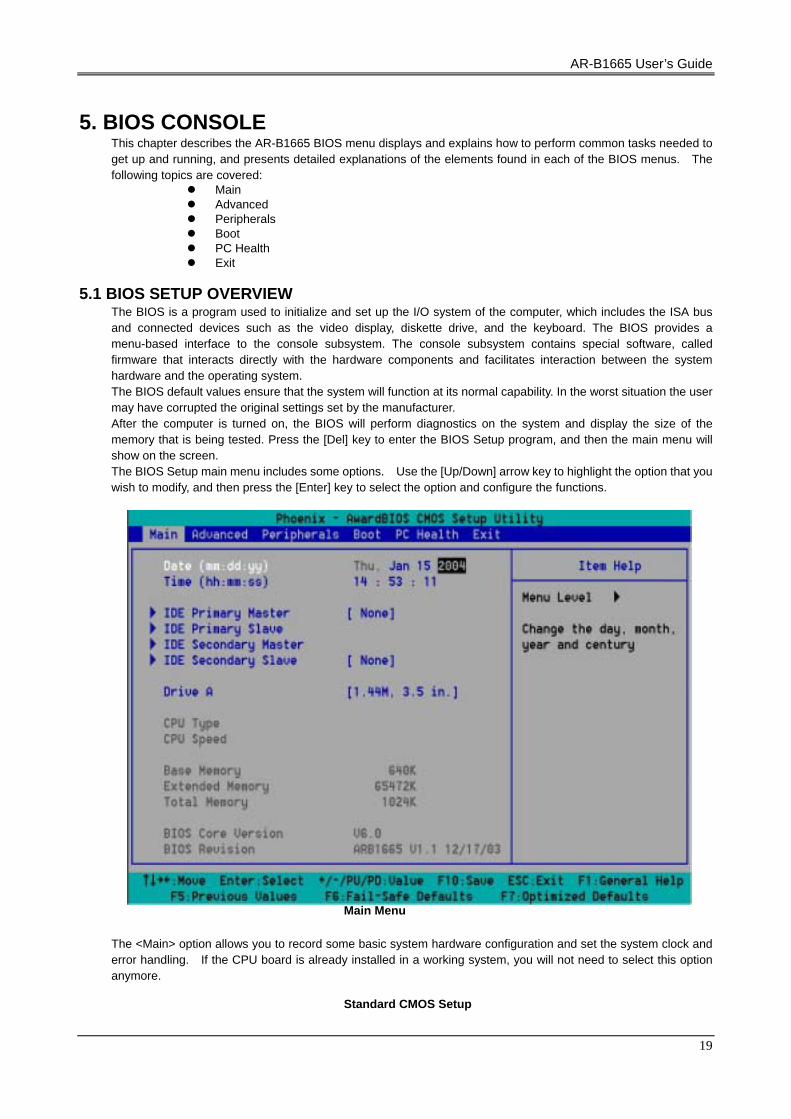
5. BIOS CONSOLE This chapter describes the AR-B1665 BIOS menu displays and explains how to perform common tasks needed to get up and running, and presents detailed explanations of the elements found in each of the BIOS menus. The following topics are covered:
Main Advanced Peripherals Boot PC Health Exit
5.1 BIOS SETUP OVERVIEW
The BIOS is a program used to initialize and set up the I/O system of the computer, which includes the ISA bus and connected devices such as the video display, diskette drive, and the keyboard. The BIOS provides a menu-based interface to the console subsystem. The console subsystem contains special software, called firmware that interacts directly with the hardware components and facilitates interaction between the system hardware and the operating system. The BIOS default values ensure that the system will function at its normal capability. In the worst situation the user may have corrupted the original settings set by the manufacturer. After the computer is turned on, the BIOS will perform diagnostics on the system and display the size of the memory that is being tested. Press the [Del] key to enter the BIOS Setup program, and then the main menu will show on the screen. The BIOS Setup main menu includes some options. Use the [Up/Down] arrow key to highlight the option that you wish to modify, and then press the [Enter] key to select the option and configure the functions.
Main Menu
The <Main> option allows you to record some basic system hardware configuration and set the system clock and error handling. If the CPU board is already installed in a working system, you will not need to select this option anymore.
Standard CMOS Setup
19

AR-B1665 User’s Guide
Date & Time Setup
Highlight the <Date> field and then press the [Page Up] /[Page Down] or [+]/[-] keys to set the current date. Follow the month, day and year format. Highlight the <Time> field and then press the [Page Up] /[Page Down] or [+]/[-] keys to set the current date. Follow the hour, minute and second format. The user can bypass the date and time prompts by creating an AUTOEXEC.BAT file. For information on how to create this file, please refer to the MS-DOS manual.
Hard Disk Setup The BIOS supports various types for user settings, The BIOS supports <Pri Master>, <Pri Slave>, <Sec Master> and <Sec Slave> so the user can install up to two hard disks. For the master and slave jumpers, please refer to the hard disk’s installation descriptions and the hard disk jumper settings in section three of this manual.
Floppy Setup The <Main> option records the types of floppy disk drives installed in the system. To enter the configuration value for a particular drive, highlight its corresponding field and then select the drive type using the left-or right-arrow key.
5.2 ADVANCED The <Advanced > option consists of configuration entries that allow you to improve your system performance, or let you set up some system features according to your preference. Some entries here are required by the CPU board’s design to remain in their default settings.
Advanced
Quick Post
This category speeds up Power On Self Test (POST) after you power on the computer. If it is set to Enabled, BIOS will shorten or skip some check items during POST.
These options determine where the system looks first for an operating system.
20

AR-B1665 User’s Guide
PS/2 Mouse Function
The setting of Enabled allows the system to detect a PS/2 mouse on boot up. If detected, IRQ12 will be used for the PS/2 mouse. IRQ 12 will be reserved for expansion cards if a PS/2 mouse is not detected. Disabled will reserve IRQ12 for expansion cards and therefore the PS/2 mouse will not function.
Onboard FDC Controller
Select Enabled if your system has a floppy disk controller (FDC) installed on the system board and you wish to use it. If you install add-on FDC or the system has no floppy drive, select Disabled in this field. The settings are: Enabled and Disabled.
Boot Up Floppy Seek
During POST, BIOS will determine if the floppy disk drive installed is 40 or 80 tracks. 360K type is 40 tracks while 760K, 1.2M and 1.44M are all 80 tracks.
On Chip USB Controller
This option can enable USB Ports or Disabled USB function.
USB Keyboard Support This option can enable or Disabled USB keyboard function.
USB Mouse Support This option can enable or Disabled USB mouse function.
ACPI Function This item allows you to Enabled/Disabled the Advanced Configuration and Power Management (ACPI). The settings are Enabled and Disabled .
ACPI Suspend Type This item will set which ACPI suspend type will be used. S1 (POS) The S1 sleeping state is low wake-up latency sleeping state. In this state, no system context is lost (CPU or chipset) and hardware maintains all system context. S3 (STR) The S3 state is a low wake-up latency sleeping sate where all system context is lost expect system memory. CPU, cache, and chipset context are lost in this state. Hardware maintains memory context and restores some CPU and L2 configuration context.
After AC Power Failure This option enable the End User to define if the system will be power-on once the AC Power is given. The Options: 1. Power Off (Always Power Off, must press Power Button to boot) 2. Power On (Auto Power On when AC power is on) 3. Last State (Depend on the Last State of the system).
21

AR-B1665 User’s Guide
5.3 PERIPHERALS
This option controls the configuration of the board’s chipset. Control keys for this screen are the same as for the previous screen.
Advanced Chipset Setup
VIA AC97 Audio This item allows you to decide to Enabled, Disabled the AC’97 Audio .
VIA OnChip LAN
This item allows you to decide to Enabled, Disabled the OnBoard LAN .
OnBoard Serial Port 1 OnBoard Serial Port 2 OnBoard Serial Port 3 OnBoard Serial Port 4
These options enable the serial port 1,2,3,and 4 on the AR-B1665 .
UART Mode Select The item allows you to determine which InfraRed (IR) function of the onboard I/O chip, this function uses.
OnBoard Parallel Port This option enables the parallel port on the AR-B1665.
Parallel Port Mode This option specifies the parallel port mode. ECP and EPP are both bi-directional data transfer schemes that adhere to the IEEE 284 specifications.
22
AR-B1665 User’s Guide
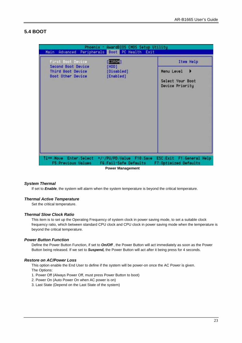
5.4 BOOT
Power Management
System Thermal If set to Enable, the system will alarm when the system temperature is beyond the critical temperature.
Thermal Active Temperature Set the critical temperature.
Thermal Slow Clock Ratio This item is to set up the Operating Frequency of system clock in power saving mode, to set a suitable clock frequency ratio, which between standard CPU clock and CPU clock in power saving mode when the temperature is beyond the critical temperature.
Power Button Function Define the Power Button Function, if set to On/Off , the Power Button will act immediately as soon as the Power Button being released. If we set to Suspend, the Power Button will act after it being press for 4 seconds.
Restore on AC/Power Loss This option enable the End User to define if the system will be power-on once the AC Power is given. The Options: 1. Power Off (Always Power Off, must press Power Button to boot) 2. Power On (Auto Power On when AC power is on) 3. Last State (Depend on the Last State of the system)
23

AR-B1665 User’s Guide
5.6 PCI/PLUG AND PLAY
This section is used to configure PCI / Plug and Play features. The <PCI & PNP Setup> option configures the PCI bus slots.
PCI / Plug And Play
Plug and Play Aware O/S
Set this option to Yes if the operating system installed in the computer is Plug and Play-aware. The BIOS only detects and enables PnP ISA adapter cards that are required for system boot. The Windows 95 operating system detects and enables all other PnP-aware adapter cards. Windows 95 is PnP-aware. Set this option <No> if the operating system (such as DOS, OS/2, Windows 3.x) does not use PnP. You must set this option correctly or PnP-aware adapter cards installed in your computer will not be configured properly.
Clear NVRAM
This sets the operating mode of the boot block area of the BIOS FLASH ROM to allow programming in the Yes setting.
OnChip VGA Frame Buffer Size
Select the VGA Frame Buffer Size Available from DDR SDRAM
PCI Latency Timer (PCI Clocks) This option sets latency of all PCI devices on the PCI bus. The settings are in units equal to PCI clocks.
Primary Graphic Adapter
This option is set to use PCI bus or AGP. The AGP mode will get system a faster processing speed.
Boot Device Select When we select the Display Device, the default is CRT. End User can choose CRT + LCD if intend to have LCD Display Function.
LCD Panel Type Select 01 for LCD with 800x600 Resolution Select 02 for LCD with 1024x768 Resolution
24

AR-B1665 User’s Guide
DMA & IRQ These options specify the bus that the named IRQs/DMAs lines are used on. These options allow you to specify IRQs/DMAs for use by legacy ISA adapter cards. These options determine if the BIOS should remove an IRQ/DMA from the pool of availability of IRQs/DMAs passed to the BIOS configurable devices. If more IRQs/DMAs must be removed from the pool, the end user can use these PCI/PnP Setup options to remove the IRQ/DMA by assigning the option to the ISA/EISA setting. The onboard I/O is configurable with BIOS.
5.7 PERIPHERAL SETUP
This section is used to configure peripheral features.
Peripheral Setup
OnBoard FDC
This option enables the floppy drive controller on the AR-B1665.
OnBoard Serial Port 1 OnBoard Serial Port 2 OnBoard Serial Port 3 OnBoard Serial Port 4
These options enable the serial port 1,2,3,and 4 on the AR-B1665.
Serial Port 3 IRQ Serial Port 4 IRQ
This option enables the user to choose the IRQ of UART 3 and 4. The system supports IRQ sharing of Serial Ports.
OnBoard Parallel Port
This option enables the parallel port on the AR-B1665.
Parallel Port Mode This option specifies the parallel port mode. ECP and EPP are both bi-directional data transfer schemes that adhere to the IEEE 284 specifications.
Parallel Port IRQ
This option enables the user to select the IRQ channel for Parallel Port.
25

AR-B1665 User’s Guide
Parallel Port DMA Channel This option is only available if the setting for the parallel Port Mode option is ECP.
OnBoard IDE
This option is to set up the operating mode of IDE controller. If the main board offers the enhanced I/O port, the choice should be <Enabled>.
OnBoard LAN This item allows you to decide to Enabled, Disabled the OnBoard LAN .
OnBoard AC’97 Audio This item allows you to decide to Enabled, Disabled the AC’97 Audio.
5.8 HARDWARE MONITOR SETUP This Section allows User to view some hardware information of the system, include Temperatures, Fan Speed, and Voltages.
Hardware Monitor Setup
26

AR-B1665 User’s Guide
5.8 AUTO-DETECT HARD DISKS
This option detects the parameters of an IDE hard disk drive, and automatically enters them into the Standard CMOS Setup screen.
5.9 PASSWORD SETTING
This BIOS Setup has an optional password feature. The system can be configured so that all users must enter a password every time the system boots or when BIOS Setup is executed. User can set either a Supervisor password or a User password. Select the appropriate password icon (Supervisor or User) from the Security section of the BIOS Setup main menu. Enter the password and press [Enter]. The screen does not display the characters entered. After the new password is entered, retype the new password as prompted and press [Enter]. If the password confirmation is incorrect, an error message appears. If the new password is entered without error, press [Esc] to return to the BIOS Main Menu. The password is stored in CMOS RAM after BIOS completes. The next time the system boots, you are prompted for the password function is present and is enabled.
Enter new supervisor password:
5.10 LOAD DEFAULT SETTING
This section permits users to select a group of settings for all BIOS Setup options. You not only can use these items to quickly set system configuration parameters, but also can choose a group of settings that have a better chance of working when the system is having configuration related problems.
5.10.1 Auto Configuration with Optimal Setting The user can load the optimal default settings for the BIOS. The Optimal default settings are best-case values that should optimize system performance. If CMOS RAM is corrupted, the optimal settings are loaded automatically.
Load high performance setting (Y/N) ? Y
5.11 BIOS EXIT This section is used to exit the BIOS main menu. After making your changes, you can either save them or exit the BIOS menu and without saving the new values.
27

AR-B1665 User’s Guide
5.12 BIOS UPDATE
The BIOS program instructions are contained within computer chips called FLASH ROMs that are located on your system board. The chips can be electronically reprogrammed, allowing you to upgrade your BIOS firmware without removing and installing chips. The AR-B1665 provides the FLASH BIOS update function for you to easily to update to a newer BIOS version. Please follow these operating steps to update to new BIOS:
Step 1:
Turn on your system and don’t detect the CONFIG.SYS and AUTOEXEC.BAT files.
Step 2:
Insert the FLASH BIOS diskette into the floppy disk drive.
Step 3:
In the MS-DOS mode, you can type the FLASH826 program. A:\>FLASH826
Step 4:
Press [ALT+F], The <File> box will show the following message, this message will be highlighted. BIOS Filename Loading … . After typing in the File name you must press<ENTER> or press <ESC> to exit.
Step 5:
And then please enter the file name to the <Enter File Name> box. And the <Message> box will show the following notice. Are you sure to write the BIOS into flash ROM?
Step 6:
Press the <Enter> key to update the new BIOS. Then the <Message> box will show the <Programming now …>.
Step 7:
When the BIOS update is successful, the message will show <Flash ROM Update Completed - Pass>.
28

AR-B1665 User’s Guide
APPENDIX A. ADDRESS MAPPING
IO Address Map
I/O MAP ASSIGNMENT 000-01F DMA controller (Master) 020-021 Interrupt controller (Master) 022-023 Chipset controller registers I/O ports. 040-05F Timer control registers. 060-06F Keyboard interface controller 070-07F RTC ports & CMOS I/O ports 080-09F DMA register 0A0-0BF Interrupt controller (Slave) 0C0-0DF DMA controller (Slave) 0F0-0FF Math coprocessor 1F0-1F8 Hard Disk controller 250-258 Super I/O 2B0-2DF Graphics adapter controller 2F8-2FF Serial port-2 360-36F Net work ports 378-37F Parallel port 3B0-3BF Monochrome & Printer adapter 3C0-3CF EGA adapter 3D0-3DF CGA adapter 3F0-3F7 Floppy disk controller 3F8-3FF Serial port-1
Memory Map:
MEMORY MAP ASSIGNMENT 0000000-009FFFF System memory used by DOS and application
00A0000-00BFFFF Display buffer memory for VGA/ EGA / CGA / MONOCHROME adapter
00C0000-00DFFFF Reserved for I/O device BIOS ROM or RAM buffer. 00E0000-00EFFFF Reserved for PCI device ROM
00F0000-00FFFFF System BIOS ROM
0100000-FFFFFFF System extension memory
29

AR-B1665 User’s Guide
30
APPENDIX B. INTERRUPT REQUEST (IRQ)
SETTING
HARDWARE USING THE SETTING
00 System timer 01 Standard 101/102-Key or Microsoft Natural Keyboard 02 Programmable interrupt controller 03 Serial Port (COM2) 04 Serial Port (COM1) 05 IRQ Holder for PCI Steering 06 Floppy Disk Controller 07 Parallel Port (LPT1) 08 RTC clock 09 ACPI 12 PS/2 Compatible Mouse Port 13 Numeric data processor 14 Primary IDE controller 15 Secondary IDE controller