aqx - air handling units · air handling units in air conditioning systems must be versatile and...
TRANSCRIPT
AQXAir Handling Units
1 About Clivet1 Clivet. Change things
2 Made by Clivet Air Handling Units - System solution
4 Air Handling Units7 About Clivet AQX
8 Quality & Certifications
9 Product information
10 Features
12 Custom made AQX Clivet
13 AQX some applications
17 Selection Program Clivet AQX CTA PRO
18 Functional sections20 General Overwiew
22 AQX unit size specifications
23 Damper
26 Filter section
30 Heating section
32 Fan section
34 Humidification system
37 Cooling section
40 Heat recovery section
42 Outdoor units AQX
43 Sound attenuator section and other options
44 Control system46 General overview
47 Integrated control panel
49 BMS Communication
CONTENTS

AQX - 1
Clivet. Change thingsH
YDRO
NIC
DIR
ECT
EXPA
NSI
ON
VRF MONO/MULTI SPLIT
APPLIED RESIDENTIAL
Solutions to ensure sustainable comfort and the well-being of people and the environment
In 30 working on the design, manufacturing and distribution of air conditioning and handling systems, combining high efficiency with minimal environmental impact, Clivet has developed solutions to ensure sustainable comfort and the well-being of people and the environment. Designing and developing year-round air conditioning solutions with innovative technologies are part of Clivet's DNA, which means the company has always been ready for the future.
2 - AQX
Made by CLIVET AIR HANDLING UNITSSystem solution
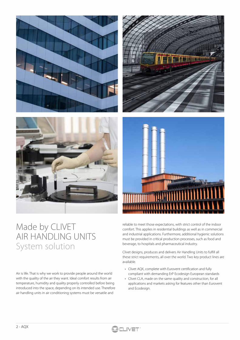
Air is life. That is why we work to provide people around the world with the quality of the air they want. Ideal comfort results from air temperature, humidity and quality properly controlled before being introduced into the space, depending on its intended use. Therefore air handling units in air conditioning systems must be versatile and
reliable to meet those expectations, with strict control of the indoor comfort. This applies in residential buildings as well as in commercial and industrial applications. Furthermore, additional hygienic solutions must be provided in critical production processes, such as food and beverage, to hospitals and pharmaceutical industry.
Clivet designs, produces and delivers Air Handling Units to fulfill all these strict requirements, all over the world. Two key product lines are available.
• Clivet AQX, complete with Eurovent certification and fully compliant with demanding ErP Ecodesign European standards
• Clivet CLA, made on the same quality and construction, for all applications and markets asking for features other than Eurovent and Ecodesign.
AQX - 3
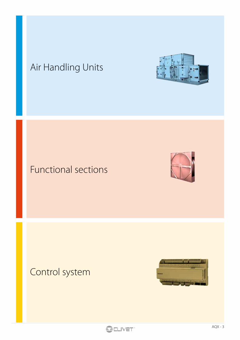
Air Handling Units
Functional sections
Control system

4 - AQX
AQX - 5
Air Handling Units
6 - AQX
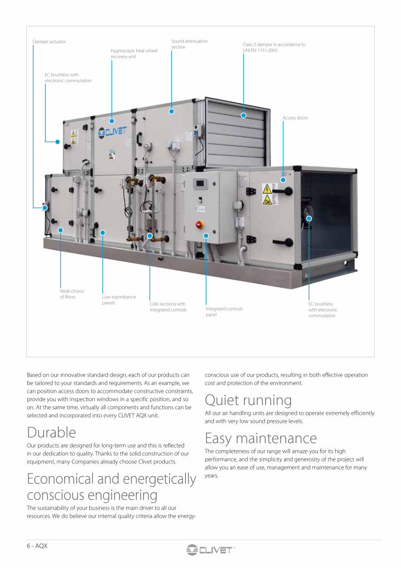
Based on our innovative standard design, each of our products can be tailored to your standards and requirements. As an example, we can position access doors to accommodate constructive constraints, provide you with inspection windows in a specific position, and so on. At the same time, virtually all components and functions can be selected and incorporated into every CLIVET AQX unit.
DurableOur products are designed for long-term use and this is reflected in our dedication to quality. Thanks to the solid construction of our equipment, many Companies already choose Clivet products.
Economical and energetically conscious engineeringThe sustainability of your business is the main driver to all our resources. We do believe our internal quality criteria allow the energy-
conscious use of our products, resulting in both effective operation cost and protection of the environment.
Quiet runningAll our air handling units are designed to operate extremely efficiently and with very low sound pressure levels.
Easy maintenanceThe completeness of our range will amaze you for its high performance, and the simplicity and generosity of the project will allow you an ease of use, management and maintenance for many years.
Damper actuator
EC brushless with electronic commutation
Hygroscopic heat wheel recovery unit
Sound attenuation section Class 3 damper in accordance to
UNI EN 1751:2003
Access doors
Wide choice of filters Low trasmittance
panels Coils sections with integrated controls Integrated controls
panel
EC brushless with electronic commutation
AQX - 7
AIR
HA
ND
LIN
G U
NIT
S
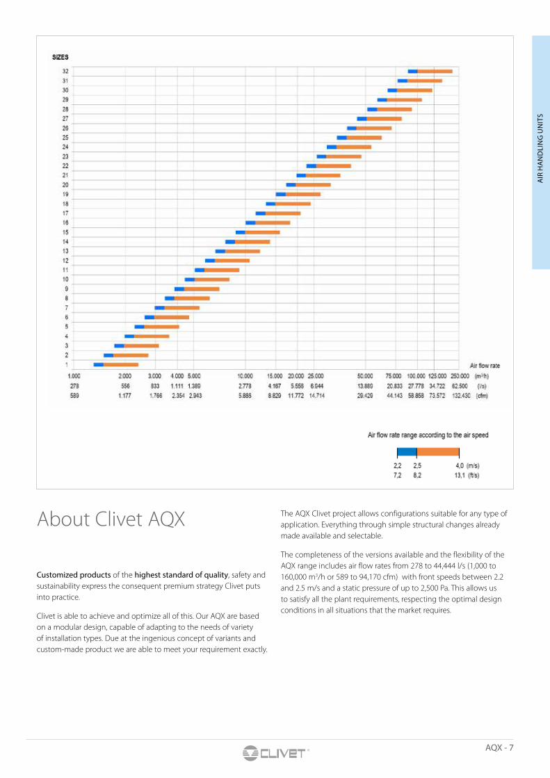
About Clivet AQX
Customized products of the highest standard of quality, safety and sustainability express the consequent premium strategy Clivet puts into practice.
Clivet is able to achieve and optimize all of this. Our AQX are based on a modular design, capable of adapting to the needs of variety of installation types. Due at the ingenious concept of variants and custom-made product we are able to meet your requirement exactly.
The AQX Clivet project allows configurations suitable for any type of application. Everything through simple structural changes already made available and selectable.
The completeness of the versions available and the flexibility of the AQX range includes air flow rates from 278 to 44,444 l/s (1,000 to 160,000 m3/h or 589 to 94,170 cfm) with front speeds between 2.2 and 2.5 m/s and a static pressure of up to 2,500 Pa. This allows us to satisfy all the plant requirements, respecting the optimal design conditions in all situations that the market requires.
8 - AQX
AHU N° 13.05.001Range AQX
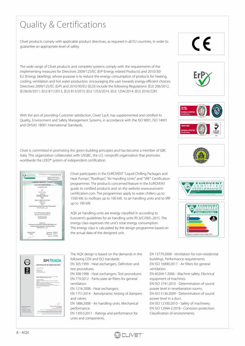
Clivet is committed in promoting the green building principles and has become a member of GBC Italia. This organization collaborates with USGBC, the U.S. nonprofit organization that promotes worldwide the LEED® system of independent certification.
Clivet products comply with applicable product directives, as required in all EU countries, in order to guarantee an appropriate level of safety.
With the aim of providing Customer satisfaction, Clivet S.p.A. has supplemented and certified its Quality, Environment and Safety Management Systems, in accordance with the ISO 9001, ISO 14001 and OHSAS 18001 International Standards.
Clivet participates in the EUROVENT “Liquid Chilling Packages and Heat Pumps”, “Rooftops”, "Air Handling Units" and "VRF" Certification programmes. The products concerned feature in the EUROVENT guide to certified products and on the website www.eurovent-certification.com. The programmes apply to water chillers up to 1500 kW, to rooftops up to 100 kW, to air handling units and to VRF up to 100 kW.
The wide range of Clivet products and complete systems comply with the requirements of the implementing measures for Directives 2009/125/EC (ErP-Energy related Products) and 2010/30/EU (Energy labelling), whose purpose is to reduce the energy consumption of products for heating, cooling, ventilation and hot water production, encouraging the user towards energy-efficient choices.Directives 2009/125/EC (ErP) and 2010/30/EU (ELD) include the following Regulations: (EU) 206/2012, (EU)626/2011; (EU) 811/2013, (EU) 813/2013; (EU) 1253/2014, (EU) 1254/2014; (EU) 2016/2281.
Quality & Certifications
The AQX design is based on the demands in the following CEN and ISO standards:EN 305:1999 - Heat exchangers. Definition and test procedures.EN 308:1998 - Heat exchangers. Test procedures.EN 779:2012 - Particulate air filters for general ventilation.EN 1216:2008 - Heat exchangers.EN 1751:2014 - Aerodynamic testing of dampers and valves.EN 1886:2008 - Air handling units. Mechanical performance.EN 13053:2011 - Ratings and performance for units and components.
EN 13779:2008 - Ventilation for non-residential buildings. Performance requirements.EN ISO 16890:2017 - Air filters for general ventilation.EN 60204-1:2006 - Machine safety. Electrical equipment of machines.EN ISO 3741:2010 - Determination of sound power level in reverberation rooms.EN ISO 5136:2009 - Determination of sound power level in a duct.EN ISO 12100:2010 - Safety of machinery.EN ISO 12944-2:2018 - Corrosion protection. Classification of environments.
AQX air handling units are energy classified in according to Eurovent’s guidelines for air handling units RS 6/C/005–2015. The energy class expresses the unit's total energy consumption. The energy class is calculated by the design programme based on the actual data of the designed unit.
AQX - 9
AIR
HA
ND
LIN
G U
NIT
S
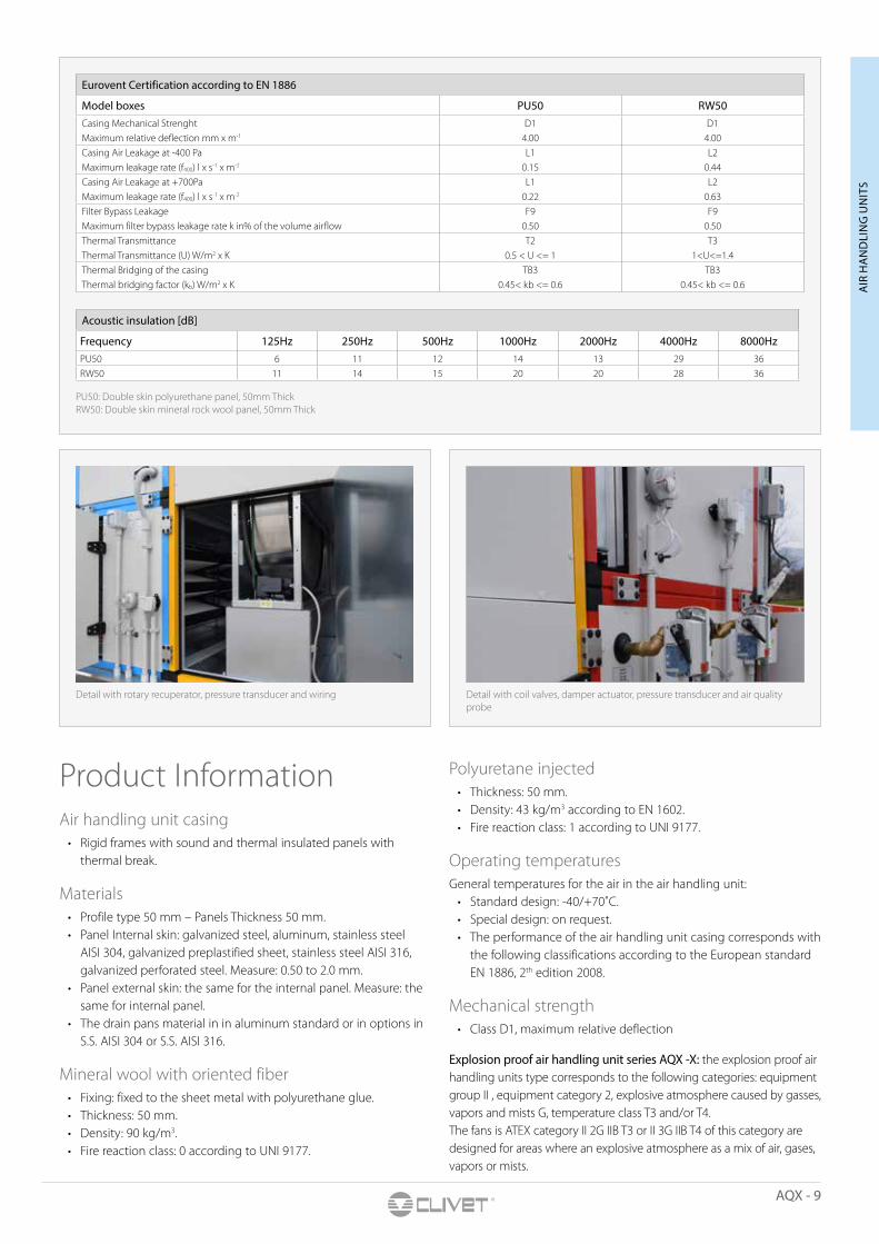
Detail with rotary recuperator, pressure transducer and wiring Detail with coil valves, damper actuator, pressure transducer and air quality probe
Product InformationAir handling unit casing
• Rigid frames with sound and thermal insulated panels with thermal break.
Materials• Profile type 50 mm – Panels Thickness 50 mm.• Panel Internal skin: galvanized steel, aluminum, stainless steel
AISI 304, galvanized preplastified sheet, stainless steel AISI 316, galvanized perforated steel. Measure: 0.50 to 2.0 mm.
• Panel external skin: the same for the internal panel. Measure: the same for internal panel.
• The drain pans material in in aluminum standard or in options in S.S. AISI 304 or S.S. AISI 316.
Mineral wool with oriented fiber• Fixing: fixed to the sheet metal with polyurethane glue.• Thickness: 50 mm.• Density: 90 kg/m3.• Fire reaction class: 0 according to UNI 9177.
Polyuretane injected• Thickness: 50 mm.• Density: 43 kg/m3 according to EN 1602.• Fire reaction class: 1 according to UNI 9177.
Operating temperaturesGeneral temperatures for the air in the air handling unit:
• Standard design: -40/+70˚C.• Special design: on request.• The performance of the air handling unit casing corresponds with
the following classifications according to the European standard EN 1886, 2th edition 2008.
Mechanical strength• Class D1, maximum relative deflection
Explosion proof air handling unit series AQX -X: the explosion proof air handling units type corresponds to the following categories: equipment group II , equipment category 2, explosive atmosphere caused by gasses, vapors and mists G, temperature class T3 and/or T4. The fans is ATEX category II 2G IIB T3 or II 3G IIB T4 of this category are designed for areas where an explosive atmosphere as a mix of air, gases, vapors or mists.
Eurovent Certification according to EN 1886
Model boxes PU50 RW50Casing Mechanical Strenght D1 D1Maximum relative deflection mm x m-1 4.00 4.00Casing Air Leakage at -400 Pa L1 L2Maximum leakage rate (f400) l x s-1 x m-2 0.15 0.44Casing Air Leakage at +700Pa L1 L2Maximum leakage rate (f400) l x s-1 x m-2 0.22 0.63Filter Bypass Leakage F9 F9Maximum filter bypass leakage rate k in% of the volume airflow 0.50 0.50Thermal Transmittance T2 T3Thermal Transmittance (U) W/m2 x K 0.5 < U <= 1 1<U<=1.4Thermal Bridging of the casing TB3 TB3Thermal bridging factor (kb) W/m2 x K 0.45< kb <= 0.6 0.45< kb <= 0.6
Acoustic insulation [dB]
Frequency 125Hz 250Hz 500Hz 1000Hz 2000Hz 4000Hz 8000HzPU50 6 11 12 14 13 29 36RW50 11 14 15 20 20 28 36
PU50: Double skin polyurethane panel, 50mm ThickRW50: Double skin mineral rock wool panel, 50mm Thick

10 - AQX
FeaturesThermal break designThe best thermal performance and the minimum heat losses are assured by the highest-level technology frame:
• Structure with aluminium profiles and ABS gasket for thermal break;
• Double chamber type profiles so that the fixings screws are totally concealed;
• Solid connecting corners made of glass-reinforced nylon, complete with thermal break;
• Concealed intermediate profile for best thermal break and reduced length;
• Modular frame for an easier transport and lifting in plant;• Section junction realised with ABS profile for a perfect thermal
break;• The base frame is independent for each section, made of
galvanized thick sheet steel.
Double skin panels• The closing panels are double skin type, with double sheet steel
and insulation through either polyurethane foam (thickness 50mm, density 43 kg/m3) or fibrous mineral wool (density 90 kg/m3), complete with gasket for thermal break.
• External sheet is coated with polyester powder, colour RAL 9001.• For best individual customisation, AQX units can be selected with
seven types of materials for the internal and external panels, with different thicknesses.
• On request, panels can be supplied with doors for inspection and service. There are solutions with hinges to allow left or right openings or even the total removal of the door, complete with internal and external handles to assure the maximum safety.
• The unit can be equipped with double-wall portholes made of polycarbonate and with sealing gaskets.
ECO water expanded polyurethane, carbon dioxide expander ODP (Ozone Depletion Potential) = 0GWP (Global Warming Potential) = 11300 times less greenhouse effect potential than traditional HCF R134a expanders.
Panel to panel Union between two sections
Aluminum panel fastening Hinges and Handles
Plastic Caps
Profile Plastic Thermal break
Aluminum intercostals
Outside AQX
Inside AQX
Profile Plastic Thermal break
Outside AQX
Inside AQX
Outside AQX
Inside AQX
Corner profile Plastic CapPanel insulation:Polyurethane or Mineral Wool
Internal sheetProfile Plastic Thermal break
Panel Plastic Thermal break
AQX - 11
AIR
HA
ND
LIN
G U
NIT
S
Frame in aluminum profile having 50x50 mm section, for its light weight and extra corrosion resistance. All profiles are double chamber type so that the fixing screws are totally concealed and there are no projections inside the AQX, and they are also fitted with a gasket to be inserted inside the profile, and to ensure maximum seal.
Basement is in galvanized steel, it is developed along the entire perimeter for each independent section, height 140 mm complete of lifting holes.
Fixing fittings are self-tapping screws, located in nylon bushes and retained in the panel with an external cap. This system completely hides the screws in the panel, and thanks to the self-centering screws, the tightness over time is ensured.
Doors for inspection and internal service can be provided with outward or inward opening for pressurized sections.
Portholes are double-wall type made of polycarbonate and with sealing gaskets. The fastening system with locking screws that only enter the polycarbonate structure (and therefore not into the sandwich panel) and the continuous internal-external gasket, prevents the formation of
condensation and ensures maximum sealing. Additional lighting can be provided inside, to simplify maintenance in all conditions.
The door opening handles provided can be adjustable so that the tightness of the seal can be maintained over time. An antifriction band, placed on the profile where the door holds, is always included in order to prevent the wear of the plastic latch (Nylon) after several closure operations.
Roof units AQX are designed for outdoor installation. In this version, the unit features a roof construction which together with the double sealing of the panels provides protection against the effects of the weather.
Control system AQX is available with a pre-installed and fully integrated control system. All units can be equipped with adjustment accessories to provide a more complete product and quick installation. These include sensors for measuring temperature, humidity and air quality, inverters, regulating valves, damper actuators, safety and control devices. The system is ready to communicate with a BMS system.
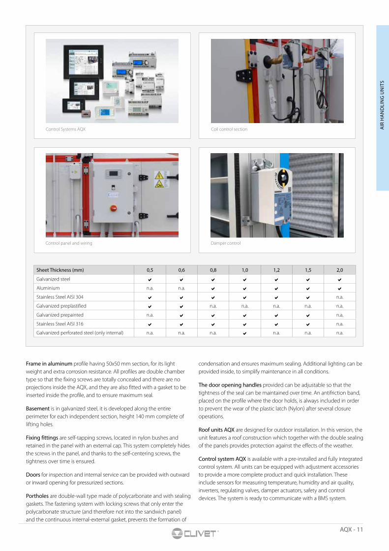
Sheet Thickness (mm) 0,5 0,6 0,8 1,0 1,2 1,5 2,0
Galvanized steel a a a a a a a
Aluminium n.a. n.a. a a a a a
Stainless Steel AISI 304 a a a a a a n.a.
Galvanized preplastified a a n.a. n.a. n.a. n.a. n.a.
Galvanized prepainted n.a. a a a a a n.a.
Stainless Steel AISI 316 a a a a a a n.a.
Galvanized perforated steel (only internal) n.a. n.a. n.a. a n.a. n.a. n.a.
Control Systems AQX Coil control section
Control panel and wiring Damper control
12 - AQX
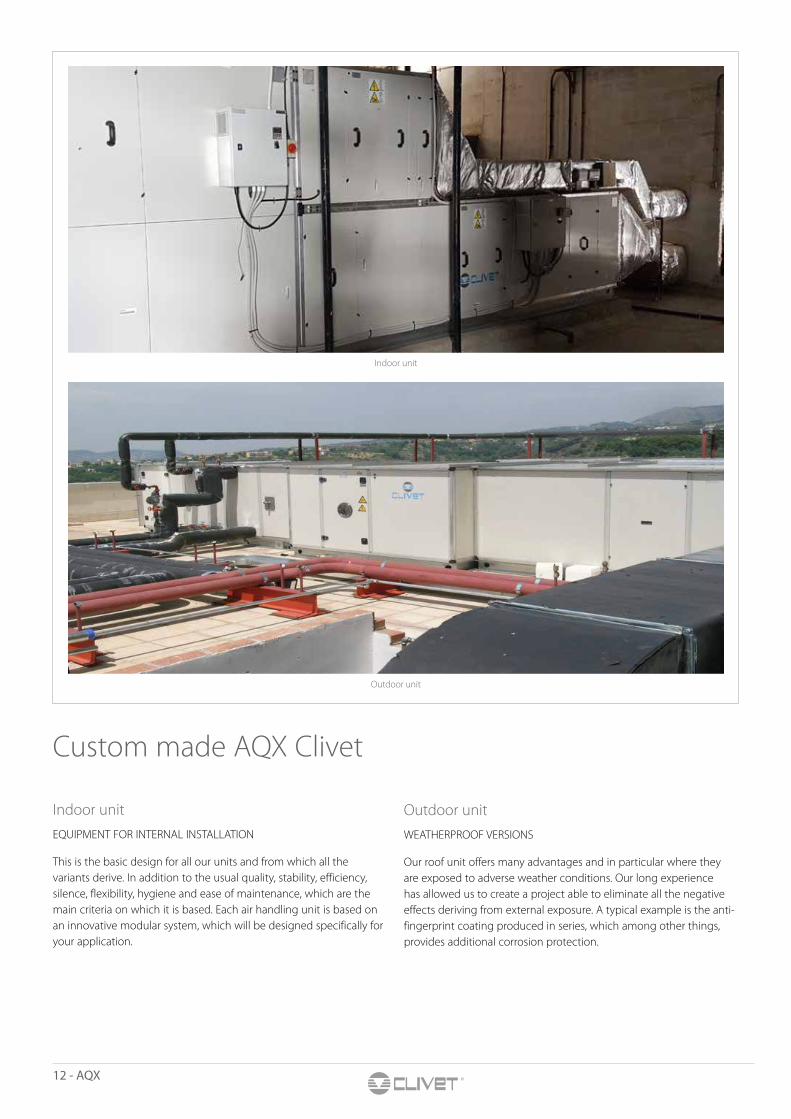
Custom made AQX Clivet
Indoor unitEQUIPMENT FOR INTERNAL INSTALLATION
This is the basic design for all our units and from which all the variants derive. In addition to the usual quality, stability, efficiency, silence, flexibility, hygiene and ease of maintenance, which are the main criteria on which it is based. Each air handling unit is based on an innovative modular system, which will be designed specifically for your application.
Outdoor unitWEATHERPROOF VERSIONS
Our roof unit offers many advantages and in particular where they are exposed to adverse weather conditions. Our long experience has allowed us to create a project able to eliminate all the negative effects deriving from external exposure. A typical example is the anti-fingerprint coating produced in series, which among other things, provides additional corrosion protection.
Indoor unit
Outdoor unit
AQX - 13
E
E F7
AIR
HA
ND
LIN
G U
NIT
SAQX some applications
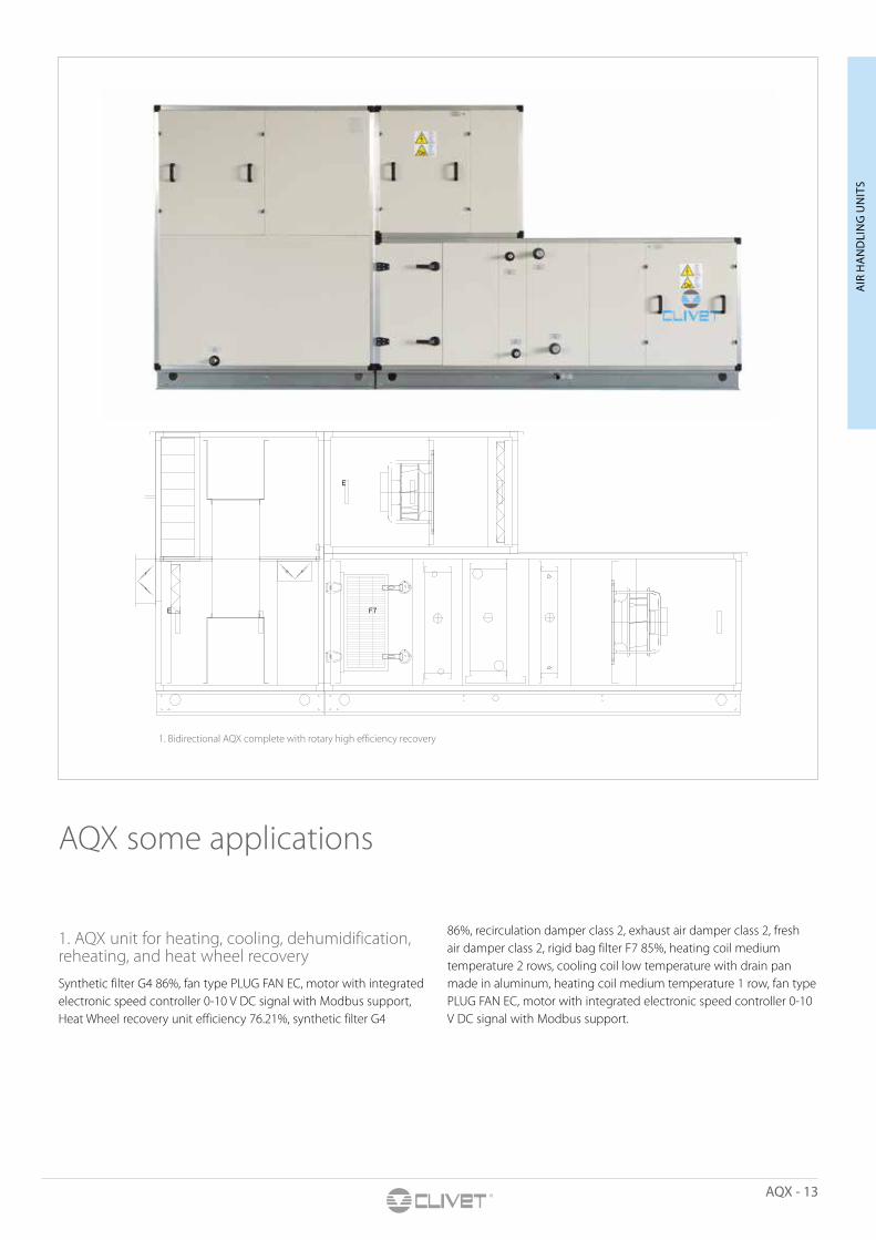
1. AQX unit for heating, cooling, dehumidification, reheating, and heat wheel recoverySynthetic filter G4 86%, fan type PLUG FAN EC, motor with integrated electronic speed controller 0-10 V DC signal with Modbus support, Heat Wheel recovery unit efficiency 76.21%, synthetic filter G4
86%, recirculation damper class 2, exhaust air damper class 2, fresh air damper class 2, rigid bag filter F7 85%, heating coil medium temperature 2 rows, cooling coil low temperature with drain pan made in aluminum, heating coil medium temperature 1 row, fan type PLUG FAN EC, motor with integrated electronic speed controller 0-10 V DC signal with Modbus support.
1. Bidirectional AQX complete with rotary high efficiency recovery
14 - AQX
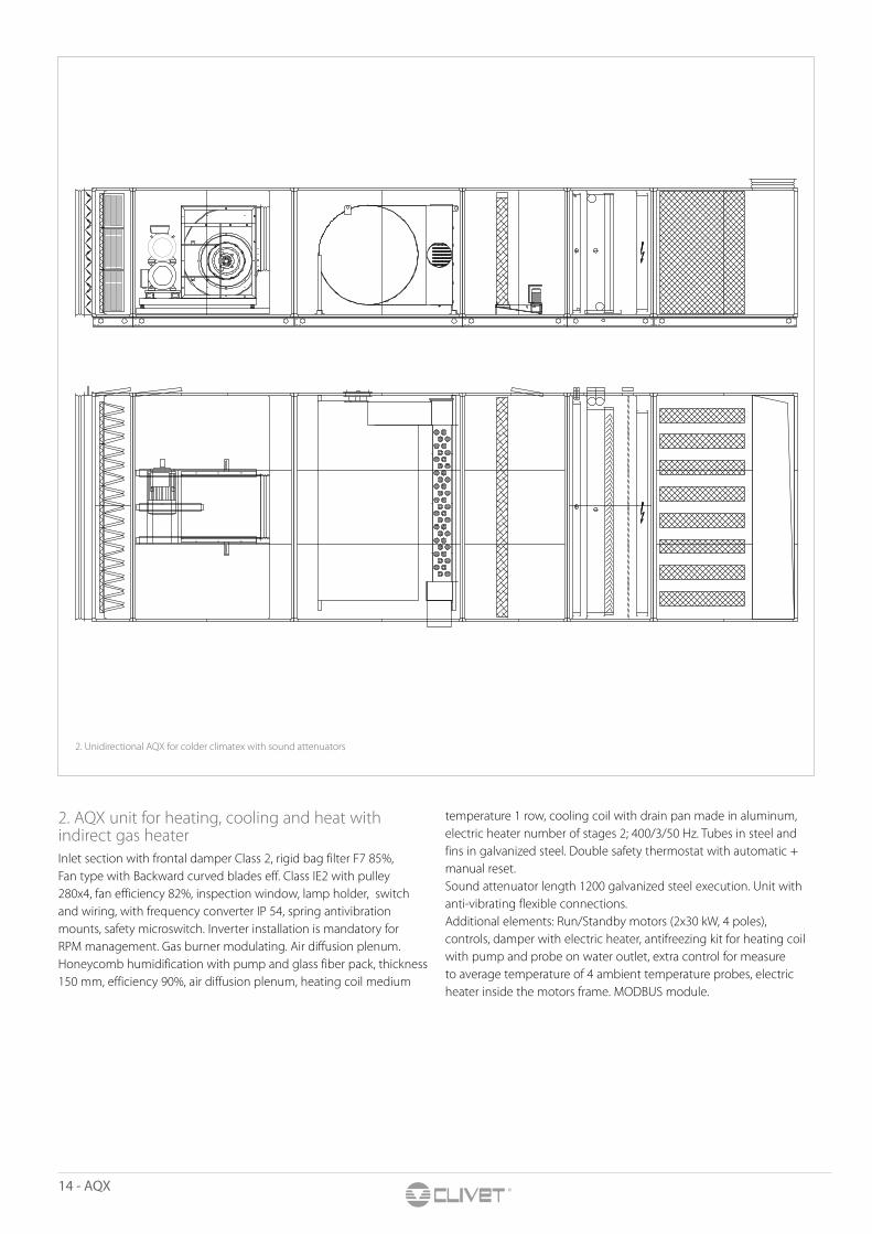
2. AQX unit for heating, cooling and heat with indirect gas heaterInlet section with frontal damper Class 2, rigid bag filter F7 85%, Fan type with Backward curved blades eff. Class IE2 with pulley 280x4, fan efficiency 82%, inspection window, lamp holder, switch and wiring, with frequency converter IP 54, spring antivibration mounts, safety microswitch. Inverter installation is mandatory for RPM management. Gas burner modulating. Air diffusion plenum. Honeycomb humidification with pump and glass fiber pack, thickness 150 mm, efficiency 90%, air diffusion plenum, heating coil medium
temperature 1 row, cooling coil with drain pan made in aluminum, electric heater number of stages 2; 400/3/50 Hz. Tubes in steel and fins in galvanized steel. Double safety thermostat with automatic + manual reset.Sound attenuator length 1200 galvanized steel execution. Unit with anti-vibrating flexible connections.Additional elements: Run/Standby motors (2x30 kW, 4 poles), controls, damper with electric heater, antifreezing kit for heating coil with pump and probe on water outlet, extra control for measure to average temperature of 4 ambient temperature probes, electric heater inside the motors frame. MODBUS module.
2. Unidirectional AQX for colder climatex with sound attenuators
AQX - 15
E.P.
AIR
HA
ND
LIN
G U
NIT
S
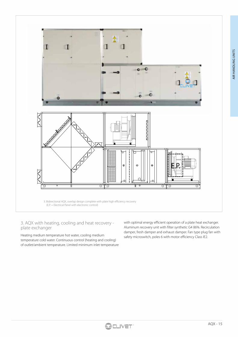
3. Bidirectional AQX, overlap design complete with plate high efficiency recovery (E.P. = Electrical Panel with electronic control)
3. AQX with heating, cooling and heat recovery - plate exchangerHeating medium temperature hot water, cooling medium temperature cold water. Continuous control (heating and cooling) of outlet/ambient temperature. Limited minimum inlet temperature
with optimal energy efficient operation of a plate heat exchanger. Aluminum recovery unit with filter synthetic G4 86%. Recirculation damper, fresh damper and exhaust damper. Fan type plug fan with safety microswitch, poles 6 with motor efficiency Class IE2.
16 - AQX
E.P.
E.P.
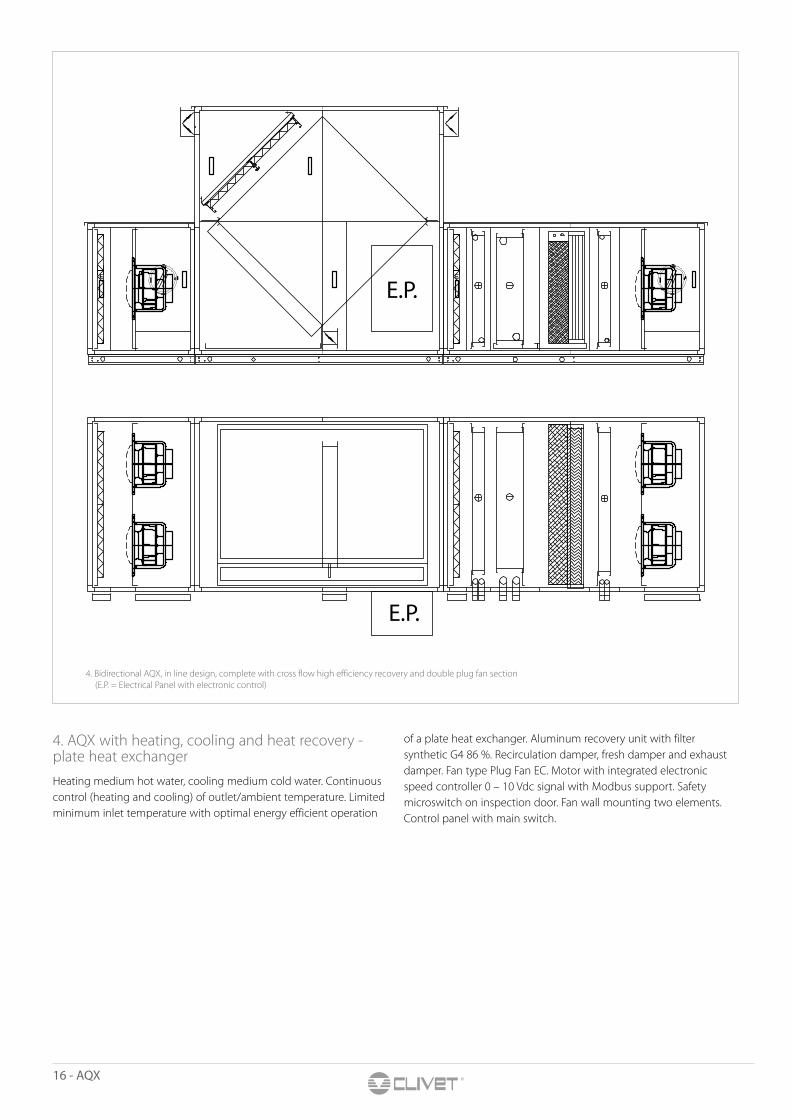
4. AQX with heating, cooling and heat recovery - plate heat exchangerHeating medium hot water, cooling medium cold water. Continuous control (heating and cooling) of outlet/ambient temperature. Limited minimum inlet temperature with optimal energy efficient operation
of a plate heat exchanger. Aluminum recovery unit with filter synthetic G4 86 %. Recirculation damper, fresh damper and exhaust damper. Fan type Plug Fan EC. Motor with integrated electronic speed controller 0 – 10 Vdc signal with Modbus support. Safety microswitch on inspection door. Fan wall mounting two elements. Control panel with main switch.
4. Bidirectional AQX, in line design, complete with cross flow high efficiency recovery and double plug fan section (E.P. = Electrical Panel with electronic control)
AQX - 17
AIR
HA
ND
LIN
G U
NIT
S
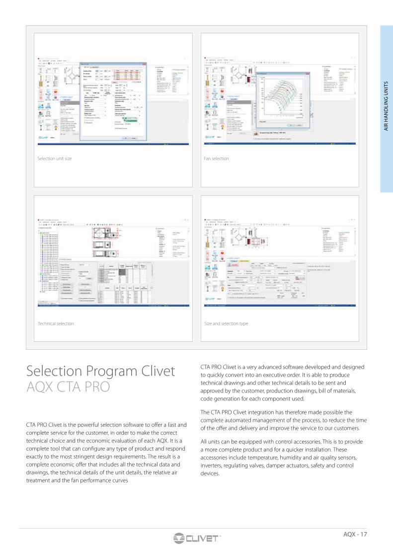
Selection Program Clivet AQX CTA PRO
CTA PRO Clivet is the powerful selection software to offer a fast and complete service for the customer, in order to make the correct technical choice and the economic evaluation of each AQX. It is a complete tool that can configure any type of product and respond exactly to the most stringent design requirements. The result is a complete economic offer that includes all the technical data and drawings, the technical details of the unit details, the relative air treatment and the fan performance curves
CTA PRO Clivet is a very advanced software developed and designed to quickly convert into an executive order. It is able to produce technical drawings and other technical details to be sent and approved by the customer, production drawings, bill of materials, code generation for each component used.
The CTA PRO Clivet integration has therefore made possible the complete automated management of the process, to reduce the time of the offer and delivery and improve the service to our customers.
All units can be equipped with control accessories. This is to provide a more complete product and for a quicker installation. These accessories include temperature, humidity and air quality sensors, inverters, regulating valves, damper actuators, safety and control devices.
Selection unit size Fan selection
Technical selection Size and selection type
18 - AQX
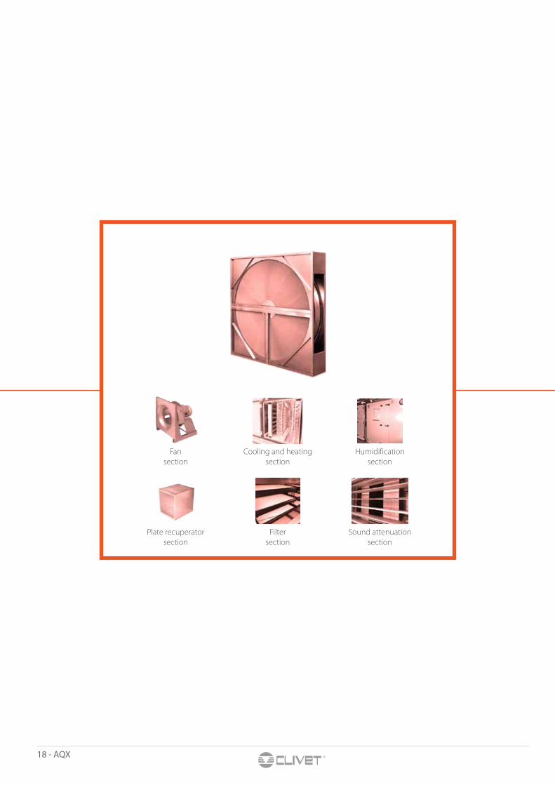
Fan section
Cooling and heating section
Humidification section
Plate recuperator section
Filter section
Sound attenuation section
AQX - 19
Functional SectionsFan, heating, humidification, cooling, heat recovery section, sound attenuation and other possible sections can be selected for each air handling unit

20 - AQX
General OverviewFan sectionFAN TYPES:
Belt Drive• Forward curved Blade, Backward curved Blade, Backward curved
Aerofoil Blade.• Anti vibration mounts: rubber or spring.• Pulley: 1 to 6 belts.• Belts trapezoidal section, type SP High Performance with variable pulley.• Motor slide: adjustable belts.• Tensions by only one bolt.• Inside canvas on air discharge.• Motors and fans: standard and ATEX.• Safety microswitch is provided on the door.
Plug Fan • Motors and fans: standard and ATEX. • Safety microswitch is provided on the door.
EC Plug Fan • Efficiency: IE4.• Motors: EC brushless with electronic commutation, driven by
0-10V signal or ModBus protocol, smaller and cost effective.• Safety Microswitch is provided on the door.
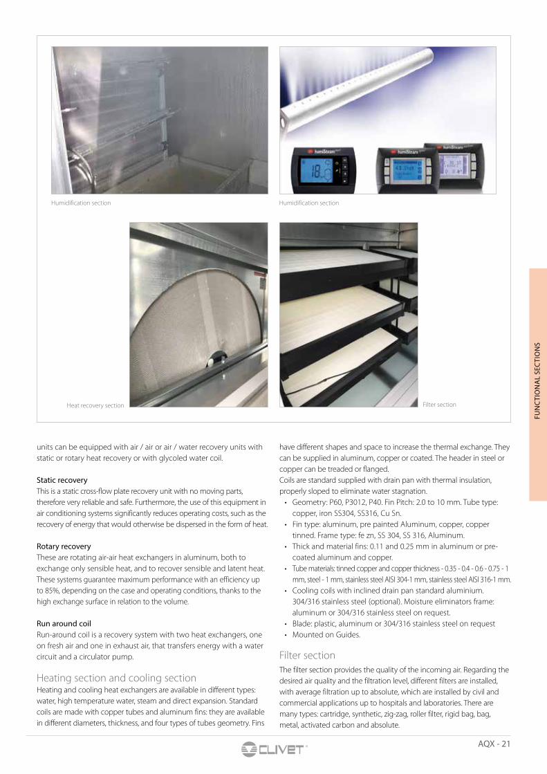
Humidification section Clivet equips its units with a wide range of humidification systems to meet specific customer needs. The systems used are of an adiabatic and isothermal type.
Adiabatic systemsThe adiabatic system consists of a cellulose fiber evaporator (Honeycomb) with a thickness of 100, 150 and 200 mm to guarantee an efficiency of 60%, 70% and 80% adequately. Evaporation units are without pump or with circulation pump, can be interfaced with the most modern supervision systems.
Isothermal systemsPressure saturated steam humidifier from 1 to 4 bar up to a capacity of 500 kg/hr. Steam produced by immersed electrodes: these are electrodes that, immersed in untreated water, exploit its conductivity, heating it up to produce steam. The maximum capacity of the system, obtained with the parallel coupling of individual units, is 180 kg/hr. Steam produced by resistance: these are electric resistors, which, immersed in drinking water, softened or demineralized, produce steam up to a maximum capacity of 180 kg/hr.
Heat recovery section In compliance with the laws in force and in response to the continuous demand for energy saving, the Clivet AQX air handling
Fan section with EC Plug fan
Cooling sectionHeating section
Fan belt drive
AQX - 21
FUN
CTI
ON
AL
SEC
TIO
NS
units can be equipped with air / air or air / water recovery units with static or rotary heat recovery or with glycoled water coil.
Static recovery This is a static cross-flow plate recovery unit with no moving parts, therefore very reliable and safe. Furthermore, the use of this equipment in air conditioning systems significantly reduces operating costs, such as the recovery of energy that would otherwise be dispersed in the form of heat.
Rotary recovery These are rotating air-air heat exchangers in aluminum, both to exchange only sensible heat, and to recover sensible and latent heat. These systems guarantee maximum performance with an efficiency up to 85%, depending on the case and operating conditions, thanks to the high exchange surface in relation to the volume.
Run around coilRun-around coil is a recovery system with two heat exchangers, one on fresh air and one in exhaust air, that transfers energy with a water circuit and a circulator pump.
Heating section and cooling section Heating and cooling heat exchangers are available in different types: water, high temperature water, steam and direct expansion. Standard coils are made with copper tubes and aluminum fins: they are available in different diameters, thickness, and four types of tubes geometry. Fins
have different shapes and space to increase the thermal exchange. They can be supplied in aluminum, copper or coated. The header in steel or copper can be treaded or flanged.Coils are standard supplied with drain pan with thermal insulation, properly sloped to eliminate water stagnation.
• Geometry: P60, P3012, P40. Fin Pitch: 2.0 to 10 mm. Tube type: copper, iron SS304, SS316, Cu Sn.
• Fin type: aluminum, pre painted Aluminum, copper, copper tinned. Frame type: fe zn, SS 304, SS 316, Aluminum.
• Thick and material fins: 0.11 and 0.25 mm in aluminum or pre-coated aluminum and copper.
• Tube materials: tinned copper and copper thickness - 0.35 - 0.4 - 0.6 - 0.75 - 1 mm, steel - 1 mm, stainless steel AISI 304-1 mm, stainless steel AISI 316-1 mm.
• Cooling coils with inclined drain pan standard aluminium. 304/316 stainless steel (optional). Moisture eliminators frame: aluminum or 304/316 stainless steel on request.
• Blade: plastic, aluminum or 304/316 stainless steel on request• Mounted on Guides.
Filter section The filter section provides the quality of the incoming air. Regarding the desired air quality and the filtration level, different filters are installed, with average filtration up to absolute, which are installed by civil and commercial applications up to hospitals and laboratories. There are many types: cartridge, synthetic, zig-zag, roller filter, rigid bag, bag, metal, activated carbon and absolute.
Humidification section Humidification section
Heat recovery section Filter section
22 - AQX
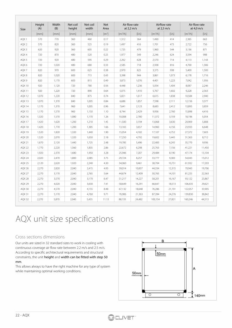
[mm] [mm] [mm] [mm] [m2] [m3/h] [l/s] [m3/h] [l/s] [m3/h] [l/s]
AQX 1 570 770 360 460 0.17 1,312 364 1,490 414 2,385 663
AQX 2 570 820 360 525 0.19 1,497 416 1,701 473 2,722 756
AQX 3 620 920 360 605 0.22 1,725 479 1,960 544 3,136 871
AQX 4 720 870 480 520 0.25 1,977 549 2,246 624 3,594 998
AQX 5 720 920 480 595 0.29 2,262 628 2,570 714 4,113 1,143
AQX 6 720 1,020 480 680 0.33 2,585 718 2,938 816 4,700 1,306
AQX 7 820 970 600 625 0.38 2,970 825 3,375 938 5,400 1,500
AQX 8 820 1,020 600 715 0.43 3,398 944 3,861 1,073 6,178 1,716
AQX 9 820 1,170 600 815 0.49 3,873 1,076 4,401 1,223 7,042 1,956
AQX 10 920 1,120 720 780 0.56 4,448 1,236 5,054 1,404 8,087 2,246
AQX 11 920 1,220 720 890 0.64 5,075 1,410 5,767 1,602 9,228 2,563
AQX 12 1,070 1,220 840 875 0.74 5,821 1,617 6,615 1,838 10,584 2,940
AQX 13 1,070 1,370 840 1,005 0.84 6,686 1,857 7,598 2,111 12,156 3,377
AQX 14 1,170 1,370 960 1,005 0.96 7,641 2,123 8,683 2,412 13,893 3,859
AQX 15 1,170 1,570 960 1,150 1.10 8,744 2,429 9,936 2,760 15,898 4,416
AQX 16 1,320 1,570 1,080 1,170 1.26 10,008 2,780 11,372 3,159 18,196 5,054
AQX 17 1,420 1,620 1,200 1,210 1.45 11,500 3,194 13,068 3,630 20,909 5,808
AQX 18 1,420 1,770 1,200 1,385 1.66 13,165 3,657 14,960 4,156 23,933 6,648
AQX 19 1,520 1,820 1,320 1,440 1.90 15,054 4,182 17,107 4,752 27,372 7,603
AQX 20 1,520 2,070 1,320 1,650 2.18 17,250 4,792 19,602 5,445 31,363 8,712
AQX 21 1,670 2,120 1,440 1,725 2.48 19,785 5,496 22,483 6,245 35,770 9,936
AQX 22 1,770 2,220 1,560 1,835 2.86 22,672 6,298 25,763 7,156 41,221 11,450
AQX 23 1,920 2,370 1,680 1,950 3.28 25,946 7,207 29,484 8,190 47,174 13,104
AQX 24 2,020 2,470 1,800 2,085 3.75 29,724 8,257 33,777 9,383 54,043 15,012
AQX 25 2,120 2,620 1,920 2,240 4.30 34,060 9,461 38,704 10,751 61,932 17,203
AQX 26 2,270 2,820 2,040 2,415 4.93 39,014 10,837 44,334 12,315 70,943 19,706
AQX 27 2,270 3,170 2,040 2,765 5.64 44,674 12,409 50,765 14,101 81,225 22,563
AQX 28 2,270 3,570 2,040 3,170 6.47 51,217 14,227 58,201 16,167 93,122 25,867
AQX 29 2,270 4,020 2,040 3,630 7.41 58,649 16,291 66,647 18,513 106,635 29,621
AQX 30 2,270 4,570 2,040 4,155 8.48 67,132 18,648 76,286 21,191 122,057 33,905
AQX 31 2,270 5,170 2,040 4,760 9.71 76,906 21,363 87,394 24,276 139,830 38,842
AQX 32 2,270 5,870 2,040 5,455 11.13 88,135 24,482 100,154 27,821 160,246 44,513
AQX unit size specifications
Cross sections dimensionsOur units are sized in 32 standard sizes to work in cooling with continuous coverage air flow rate between 2.2 m/s and 2.5 m/s.According to specific architectural requirements and structural constraints, the unit height and width can be fitted with step 50 mm.This allows always to have the right machine for any type of system while maintaining optimal working conditions.
SizeHeight
(A)Width
(B)Net coil height
Net coil width
Net Area
Air flow rate at 2,2 m/s
Airflow rate at 2,5 m/s
Air flow rate at 4,0 m/s
AQX - 23
FUN
CTI
ON
AL
SEC
TIO
NS
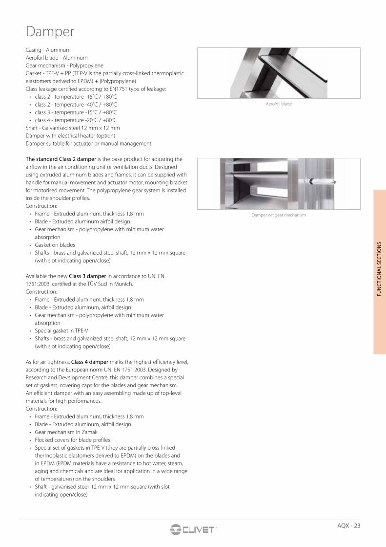
DamperCasing - AluminumAerofoil blade - AluminumGear mechanism - PolypropyleneGasket - TPE-V + PP (TEP-V is the partially cross-linked thermoplastic elastomers derived to EPDM) + (Polypropylene)Class leakage certified according to EN1751 type of leakage:
• class 2 - temperature -15°C / +80°C• class 2 - temperature -40°C / +80°C• class 3 - temperature -15°C / +80°C• class 4 - temperature -20°C / +80°C
Shaft - Galvanised steel 12 mm x 12 mmDamper with electrical heater (option)Damper suitable for actuator or manual management.
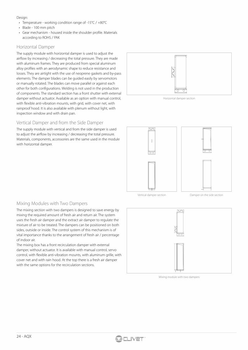
The standard Class 2 damper is the base product for adjusting the airflow in the air conditioning unit or ventilation ducts. Designed using extruded aluminum blades and frames, it can be supplied with handle for manual movement and actuator motor, mounting bracket for motorised movement. The polypropylene gear system is installed inside the shoulder profiles.Construction:
• Frame - Extruded aluminum, thickness 1.8 mm• Blade - Extruded aluminum airfoil design• Gear mechanism - polypropylene with minimum water
absorption• Gasket on blades• Shafts - brass and galvanized steel shaft, 12 mm x 12 mm square
(with slot indicating open/close)
Available the new Class 3 damper in accordance to UNI EN 1751:2003, certified at the TÜV Sud in Munich.Construction:
• Frame - Extruded aluminum, thickness 1.8 mm• Blade - Extruded aluminum, airfoil design• Gear mechanism - polypropylene with minimum water
absorption• Special gasket in TPE-V• Shafts - brass and galvanized steel shaft, 12 mm x 12 mm square
(with slot indicating open/close)
As for air tightness, Class 4 damper marks the highest efficiency level, according to the European norm UNI EN 1751:2003. Designed byResearch and Development Centre, this damper combines a special set of gaskets, covering caps for the blades and gear mechanism. An efficient damper with an easy assembling made up of top-level materials for high performances.Construction:
• Frame - Extruded aluminum, thickness 1.8 mm• Blade - Extruded aluminum, airfoil design• Gear mechanism in Zamak• Flocked covers for blade profiles• Special set of gaskets in TPE-V (they are partially cross-linked
thermoplastic elastomers derived to EPDM) on the blades and in EPDM (EPDM materials have a resistance to hot water, steam, aging and chemicals and are ideal for application in a wide range of temperatures) on the shoulders
• Shaft - galvanised steel, 12 mm x 12 mm square (with slot indicating open/close)
Aerofoil blade
Damper wit gear mechanism
24 - AQX
Design:• Temperature - working condition range of -15°C / +80°C• Blade - 100 mm pitch• Gear mechanism - housed inside the shoulder profile. Materials
according to ROHS / PAK
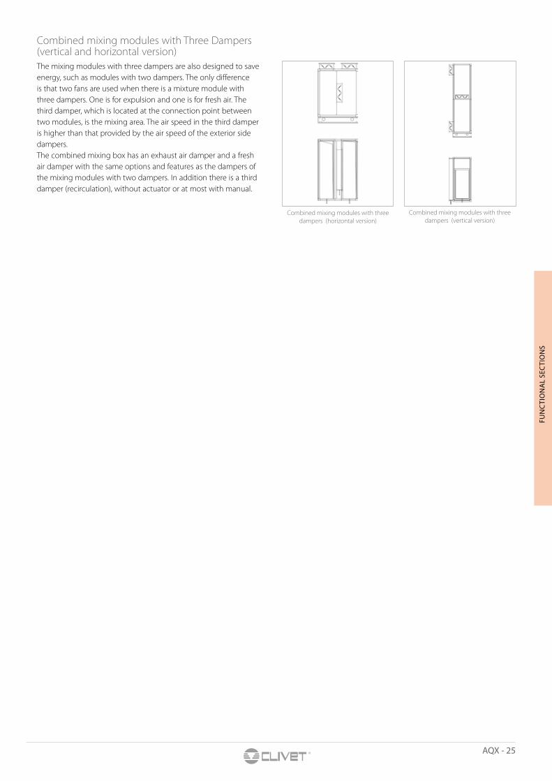
Horizontal Damper The supply module with horizontal damper is used to adjust the airflow by increasing / decreasing the total pressure. They are made with aluminum frames. They are produced from special aluminum alloy profiles with an aerodynamic shape to reduce resistance and losses. They are airtight with the use of neoprene gaskets and by-pass elements. The damper blades can be guided easily by servomotors or manually rotated. The blades can move parallel or against each other for both configurations. Welding is not used in the production of components. The standard section has a front shutter with external damper without actuator. Available as an option with manual control, with flexible anti-vibration mounts, with grid, with cover net, with rainproof hood. It is also available with plenum without light, with inspection window and with drain pan.
Vertical Damper and from the Side DamperThe supply module with vertical and from the side damper is used to adjust the airflow by increasing / decreasing the total pressure. Materials, components, accessories are the same used in the module with horizontal damper.
Mixing Modules with Two DampersThe mixing section with two dampers is designed to save energy by mixing the required amount of fresh air and return air. The system uses the fresh air damper and the extract air damper to regulate the mixture of air to be treated. The dampers can be positioned on both sides, outside or inside. The control system of this mechanism is of vital importance thanks to the arrangement of fresh air / percentage of indoor air.The mixing box has a front recirculation damper with external damper, without actuator. It is available with manual control, servo control, with flexible anti-vibration mounts, with aluminum grille, with cover net and with rain hood. At the top there is a fresh air damper with the same options for the recirculation sections.
Vertical damper section Damper on the side section
Mixing module with two dampers
Horizontal damper section
AQX - 25
FUN
CTI
ON
AL
SEC
TIO
NS
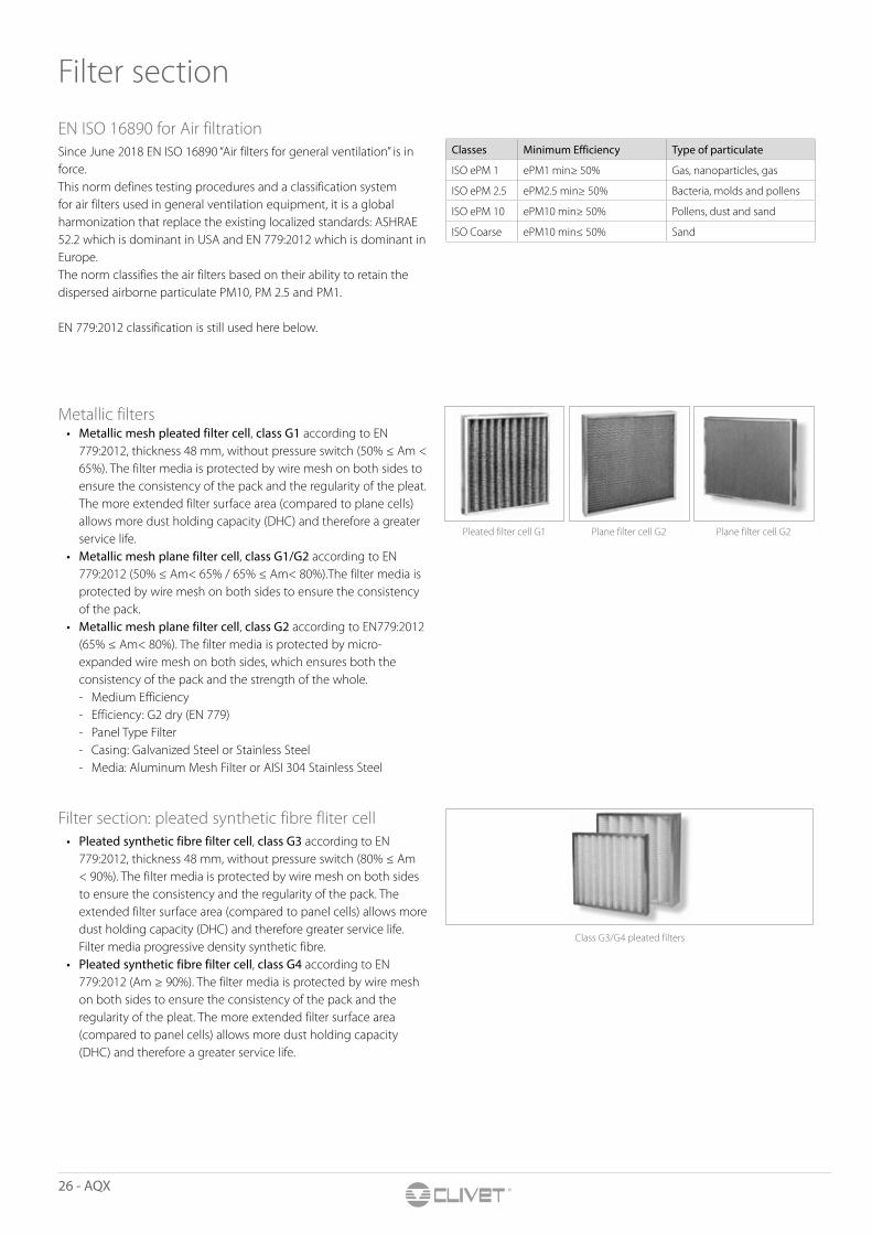
Combined mixing modules with three dampers (horizontal version)
Combined mixing modules with three dampers (vertical version)
Combined mixing modules with Three Dampers (vertical and horizontal version)The mixing modules with three dampers are also designed to save energy, such as modules with two dampers. The only difference is that two fans are used when there is a mixture module with three dampers. One is for expulsion and one is for fresh air. The third damper, which is located at the connection point between two modules, is the mixing area. The air speed in the third damper is higher than that provided by the air speed of the exterior side dampers.The combined mixing box has an exhaust air damper and a fresh air damper with the same options and features as the dampers of the mixing modules with two dampers. In addition there is a third damper (recirculation), without actuator or at most with manual.
26 - AQX
Filter section
EN ISO 16890 for Air filtrationSince June 2018 EN ISO 16890 “Air filters for general ventilation” is in force.This norm defines testing procedures and a classification system for air filters used in general ventilation equipment, it is a global harmonization that replace the existing localized standards: ASHRAE 52.2 which is dominant in USA and EN 779:2012 which is dominant in Europe. The norm classifies the air filters based on their ability to retain the dispersed airborne particulate PM10, PM 2.5 and PM1.
EN 779:2012 classification is still used here below.
Metallic filters• Metallic mesh pleated filter cell, class G1 according to EN
779:2012, thickness 48 mm, without pressure switch (50% ≤ Am < 65%). The filter media is protected by wire mesh on both sides to ensure the consistency of the pack and the regularity of the pleat. The more extended filter surface area (compared to plane cells) allows more dust holding capacity (DHC) and therefore a greater service life.
• Metallic mesh plane filter cell, class G1/G2 according to EN 779:2012 (50% ≤ Am< 65% / 65% ≤ Am< 80%).The filter media is protected by wire mesh on both sides to ensure the consistency of the pack.
• Metallic mesh plane filter cell, class G2 according to EN779:2012 (65% ≤ Am< 80%). The filter media is protected by micro-expanded wire mesh on both sides, which ensures both the consistency of the pack and the strength of the whole. - Medium Efficiency - Efficiency: G2 dry (EN 779) - Panel Type Filter - Casing: Galvanized Steel or Stainless Steel - Media: Aluminum Mesh Filter or AISI 304 Stainless Steel
Filter section: pleated synthetic fibre fliter cell • Pleated synthetic fibre filter cell, class G3 according to EN
779:2012, thickness 48 mm, without pressure switch (80% ≤ Am < 90%). The filter media is protected by wire mesh on both sides to ensure the consistency and the regularity of the pack. The extended filter surface area (compared to panel cells) allows more dust holding capacity (DHC) and therefore greater service life. Filter media progressive density synthetic fibre.
• Pleated synthetic fibre filter cell, class G4 according to EN 779:2012 (Am ≥ 90%). The filter media is protected by wire mesh on both sides to ensure the consistency of the pack and the regularity of the pleat. The more extended filter surface area (compared to panel cells) allows more dust holding capacity (DHC) and therefore a greater service life.
Class G3/G4 pleated filters
Pleated filter cell G1
Classes Minimum Efficiency Type of particulate
ISO ePM 1 ePM1 min≥ 50% Gas, nanoparticles, gas
ISO ePM 2.5 ePM2.5 min≥ 50% Bacteria, molds and pollens
ISO ePM 10 ePM10 min≥ 50% Pollens, dust and sand
ISO Coarse ePM10 min≤ 50% Sand
Plane filter cell G2 Plane filter cell G2
AQX - 27
FUN
CTI
ON
AL
SEC
TIO
NS
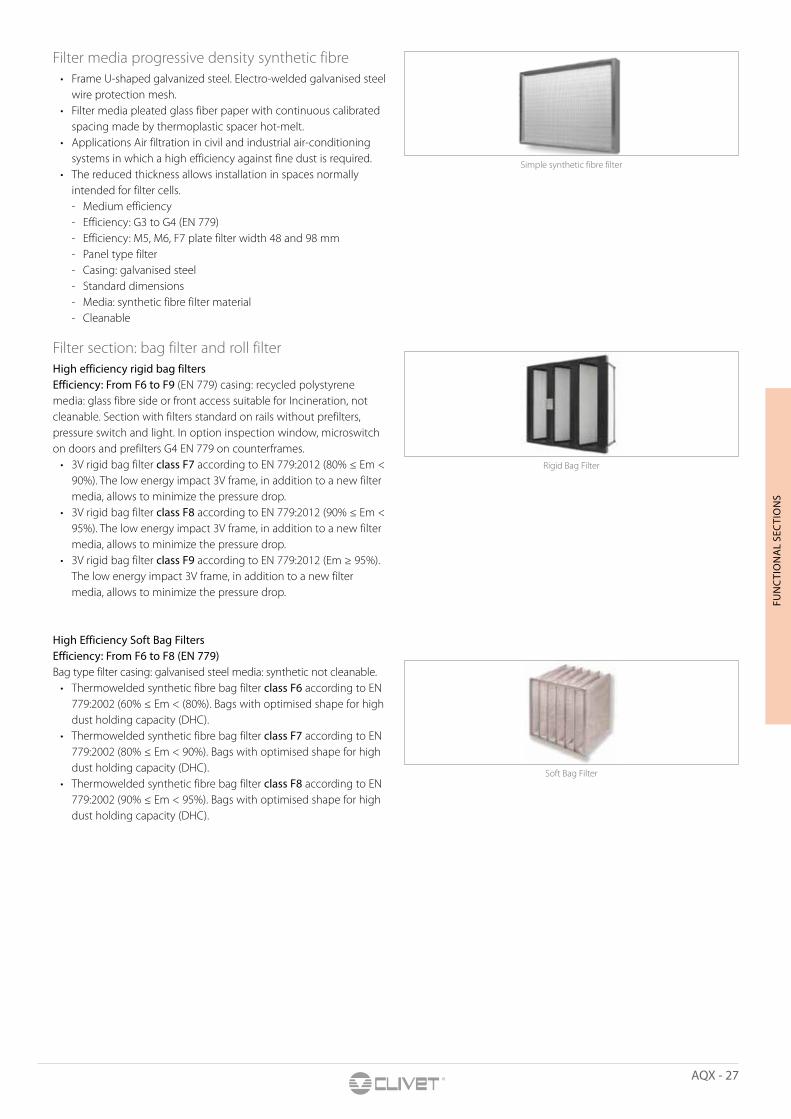
Filter media progressive density synthetic fibre• Frame U-shaped galvanized steel. Electro-welded galvanised steel
wire protection mesh.• Filter media pleated glass fiber paper with continuous calibrated
spacing made by thermoplastic spacer hot-melt.• Applications Air filtration in civil and industrial air-conditioning
systems in which a high efficiency against fine dust is required.• The reduced thickness allows installation in spaces normally
intended for filter cells. - Medium efficiency - Efficiency: G3 to G4 (EN 779) - Efficiency: M5, M6, F7 plate filter width 48 and 98 mm - Panel type filter - Casing: galvanised steel - Standard dimensions - Media: synthetic fibre filter material - Cleanable
Filter section: bag filter and roll filterHigh efficiency rigid bag filtersEfficiency: From F6 to F9 (EN 779) casing: recycled polystyrene media: glass fibre side or front access suitable for Incineration, not cleanable. Section with filters standard on rails without prefilters, pressure switch and light. In option inspection window, microswitch on doors and prefilters G4 EN 779 on counterframes.
• 3V rigid bag filter class F7 according to EN 779:2012 (80% ≤ Em < 90%). The low energy impact 3V frame, in addition to a new filter media, allows to minimize the pressure drop.
• 3V rigid bag filter class F8 according to EN 779:2012 (90% ≤ Em < 95%). The low energy impact 3V frame, in addition to a new filter media, allows to minimize the pressure drop.
• 3V rigid bag filter class F9 according to EN 779:2012 (Em ≥ 95%). The low energy impact 3V frame, in addition to a new filter media, allows to minimize the pressure drop.
High Efficiency Soft Bag Filters Efficiency: From F6 to F8 (EN 779)Bag type filter casing: galvanised steel media: synthetic not cleanable.
• Thermowelded synthetic fibre bag filter class F6 according to EN 779:2002 (60% ≤ Em < (80%). Bags with optimised shape for high dust holding capacity (DHC).
• Thermowelded synthetic fibre bag filter class F7 according to EN 779:2002 (80% ≤ Em < 90%). Bags with optimised shape for high dust holding capacity (DHC).
• Thermowelded synthetic fibre bag filter class F8 according to EN 779:2002 (90% ≤ Em < 95%). Bags with optimised shape for high dust holding capacity (DHC).
Simple synthetic fibre filter
Rigid Bag Filter
Soft Bag Filter

28 - AQX
Automatic Roll Filter G3 The section is provided without light and without manometer. In option with microswitch on doors and with inspection window.
• Efficiency: G3• Casing: galvanised steel• Media: synthetic fibre• Not cleanable• Motor: 230/1/50• Power consumption: 160 - 240 Watt• Temperature: -10 °C / 40 °C• Control panel with safety button, tubular motor, differential
pressure switch• Completely wired
Main features:• Filter with automatic unwinding and replacement of the filter
fabric with a roller system. The upper coil (dragged) provides the new support, the lower coil (loader) collects the clogged filter material. Between the two both equipped with protective casing, there is a window that contains, inside the guides, the portion of material exposed to the flow. The electric part consists of a control panel complete with key and safety button, a tubular motor with thermal switch positioned inside the lower roller, an adjustable pressure switch adjustable from 50 Pa to 500 Pa, an electromagnetic brake and a microswitch end of the race. When the critical pressure drop is reached, the pressure switch controls the release of the brake and the function of the rotating motor, in order to change the portion of filter media exposed to the airflow. The end of the microswitch roller interrupts this cycle and provides an alarm signal when the new filter material falls below the safety limit, while the electromagnetic brake prevents spontaneous unwinding of the clean roll and keeps the portion of material exposed to the flow extract.
• Construction: roll protective carters, support frame, pulling rolls and lateral guide rails in galvanised steel.
• Special executions: with support frames for bag filters in cascade.
Filter section: carbon filtersActivated carbon filtersSection with filters high efficiency cartridges, available in casing galvanized steel or rigid bag. Section without pressure switch, without light. In option with inspection window, microswitch on doors and with the support plate in stainless steel. For the bag rigid carbon filters are available in option galvanized steel counterframes with filters G4.
Casing: galvanised steel• Media: micro granulated activated carbon in cylindrical cartridge• Not cleanable• Temperature: up to 50 °C• Humidity: up to 70%• Media: standard is for organic substance• Options for other gas• Options: stainless steel plate• G4 filters are suggested downstream• Activated carbon cylindrical cartridge filter. It is commonly used
for the deodorization and the chemical-physical adsorption of gaseous pollutants. The design of a purification system with activated carbon requires the knowledge of the chemical composition of pollutants, the relative concentration and the thermo-hygrometric conditions of the air to be treated.
Cartridge carbon filter
Automatic roll filter Automatic roll filter system
Roll filter section

AQX - 29
FUN
CTI
ON
AL
SEC
TIO
NS
Casing: rigid bag• Media: micro granulated active carbon• Frame: plastic• Temperature: up to 50 °C• Humidity: up to 70%• Versions suitable for incineration available• G4 filters are suggested downstream• Activated carbon 4V rigid bag filter for the deodorisation. The
4 V solution (8 packs), offers a high filter surface and a long life service.
Media Absolute Filters and HEPA Absolute Filters (class from E10 to H14)
• Multi-V filter EPA class E10 according to EN 1822:2010 (E ≥ 85% @ MPPS). The 6-V solution (3 V for the half size) offers an extended filter surface, which allows high nominal air flows.
• Multi-V filter EPA class E12 according to EN 1822:2010 (E ≥ 99.5%). The 6V solution (3V for the half size) offers an extended filter surface, which allows high nominal air flows.
• Multi-V filter HEPA class H13 according to EN 1822:2010 (Eintegral ≥ 99.95% - Elocal ≥ 99.75% ). The 6V solution (3V for the half size) offers an extended filter surface, which allows high nominal air flows.
• Multi-V filter HEPA class H14 according to EN 1822:2010 (Eintegral ≥ 99.995% - Elocal ≥ 99.975%.). The 6V solution (3V for the half size) offers an extended filter surface, which allows high nominal air flows.
Filter section inspection door• Access from side: simpifies maintenance of the filter section
• Frontal access filter: improves the fixing on filter frame and reduces the bypass leakage
Rigid bag carbon filter
Absolute filter class E
Absolute filter class H
Bag filter Pre filter + Bag filter
Bag filter Pre filter + Bag filter

30 - AQX
Heating sectionHeating section with water heaterDepending on the conditions, the heating coils are in this module. The coils used with steam or hot water are made of copper tubes with aluminum fins. Optionally it is possible to use steel pipes / fins in steel, stainless steel or galvanized steel pipes or electrical resistors. The heat exchanger is designed to achieve the optimal pressure drop on both sides of the air and water. Usually the heaters of the heating coil are equipped with carbon steel pipes, while the heads of the steam coils are made of copper. The water inlet sides for the heating coils come from the bottom of it while the steam inlet is the top of the steam coil. The air speed on this coil can exceed 3 m/ s if there is no cooling coil after it. All coils must be selected with the certified Eurovent software and suitable for working with a pressure gauge of 13 bar. The test pressure must be 20 bar.Options: U-shaped drainage manifold that works with the pressure principle of the water pressure gauge, preventing the wastewater from going in one direction. Thermostat that avoids any possible freezing occasion.
Geometry: • P60, P3012, P40. • Fin Pitch: 2.0 to 10 mm. • Tube type: copper, iron SS304, SS316, CuSn. • Fin type: aluminum, pre painted Al, copper, copper tinned.• Frame type: fe zn, SS 304, SS 316, aluminum. • Fluid water or water with ethylenic or propylenic in weight or
volume.
Heating section with steam heaterThe steam coil consists of a frame and a pack of aluminum fins, in which the copper tubes are assembled, collected and distributed. Aluminum fins and copper tubes are joined by mechanical expansion. The manifold and distribution pipes are made of steel and are equipped with a treated or flanged connection and an air vent and discharge valve. The frame of the steam heater protects the elbows of the pipe and serves to mount the heater in the unit. The coil heater is inserted into the housing by guides that facilitate its removal. The manifold tube, the distribution tube and the welding joints are protected against corrosion with a temperature-resistant coating.The water inlet sides for the heating coils come from the bottom of it while the steam inlet is the top of the steam coil. The air speed on this coil can exceed 3 m/s if there is no cooling coil after it.
Geometry: • P60, P3012, P40. • Fin Pitch: 2.0 to 10 mm. • Tube type: copper, iron SS304, SS316, CuSn. Fin type: aluminum,
pre painted Al, copper, copper tinned. • Frame type: fe zn, SS 304, SS 316, Aluminum. • Fluid steam.
Detail heating section Detail heating section
Steam coils
AQX - 31
FUN
CTI
ON
AL
SEC
TIO
NS
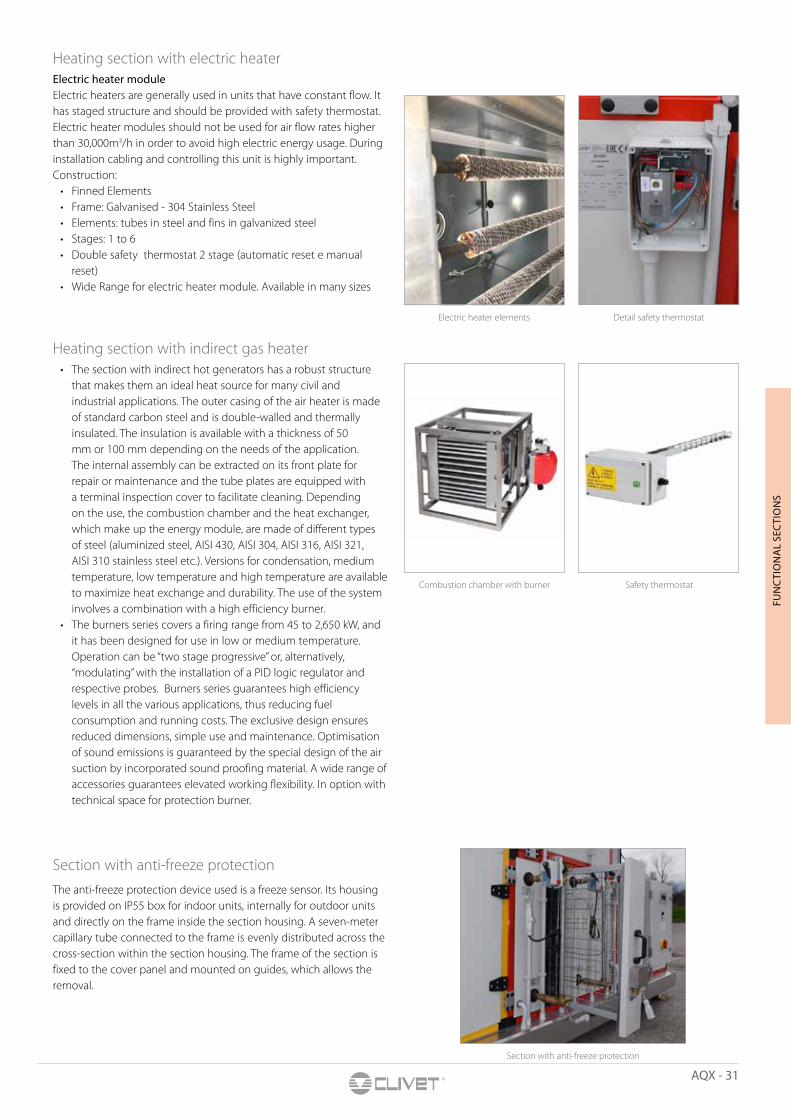
Heating section with electric heaterElectric heater module Electric heaters are generally used in units that have constant flow. It has staged structure and should be provided with safety thermostat. Electric heater modules should not be used for air flow rates higher than 30,000m3/h in order to avoid high electric energy usage. During installation cabling and controlling this unit is highly important.Construction:
• Finned Elements• Frame: Galvanised - 304 Stainless Steel• Elements: tubes in steel and fins in galvanized steel• Stages: 1 to 6 • Double safety thermostat 2 stage (automatic reset e manual
reset)• Wide Range for electric heater module. Available in many sizes
Heating section with indirect gas heater• The section with indirect hot generators has a robust structure
that makes them an ideal heat source for many civil and industrial applications. The outer casing of the air heater is made of standard carbon steel and is double-walled and thermally insulated. The insulation is available with a thickness of 50 mm or 100 mm depending on the needs of the application. The internal assembly can be extracted on its front plate for repair or maintenance and the tube plates are equipped with a terminal inspection cover to facilitate cleaning. Depending on the use, the combustion chamber and the heat exchanger, which make up the energy module, are made of different types of steel (aluminized steel, AISI 430, AISI 304, AISI 316, AISI 321, AISI 310 stainless steel etc.). Versions for condensation, medium temperature, low temperature and high temperature are available to maximize heat exchange and durability. The use of the system involves a combination with a high efficiency burner.
• The burners series covers a firing range from 45 to 2,650 kW, and it has been designed for use in low or medium temperature. Operation can be “two stage progressive” or, alternatively, “modulating” with the installation of a PID logic regulator and respective probes. Burners series guarantees high efficiency levels in all the various applications, thus reducing fuel consumption and running costs. The exclusive design ensures reduced dimensions, simple use and maintenance. Optimisation of sound emissions is guaranteed by the special design of the air suction by incorporated sound proofing material. A wide range of accessories guarantees elevated working flexibility. In option with technical space for protection burner.
Section with anti-freeze protectionThe anti-freeze protection device used is a freeze sensor. Its housing is provided on IP55 box for indoor units, internally for outdoor units and directly on the frame inside the section housing. A seven-meter capillary tube connected to the frame is evenly distributed across the cross-section within the section housing. The frame of the section is fixed to the cover panel and mounted on guides, which allows the removal.
Electric heater elements Detail safety thermostat
Combustion chamber with burner Safety thermostat
Section with anti-freeze protection

32 - AQX
Belt drive fan Direct drive fan
Plug fan EC plug fan
EC plug fan Detail EC plug fan, inlet air
Fan section• Belt drive fan module - This module contains the blower and
the housing fan placed on supports which can slide on rails using vibration absorber. All fans are certified and their optimum operation points are specified on the computer. To prevent conduction of vibration and noise, created during operation, into the frame, rails holding the fan is connected to the frame with springs or rubber insulators. Fan outlet is connected to the module outlet using flexible elements. The fans are driven utilizing belt and pulley systems. The pulley are mounted onto the shaft by using conical fittings. The belt tension system is simple and designed to easy access. The electric motors are 2, 4, or 6 poles, 380V, 50Hz, IP 56 protection class depending on the fan. The nominal power of the motor is selected to be 20% above the shaft power (safety factor). Variable speed, direct-coupled motor-fan combinations are also available upon request. All rotary parts used in the module are dynamically balanced.
• Plug fan module - Plug fan module is a centrifugal fan with an impeller with backward curved blades. Impeller part is directly placed on the motor shaft. Since there are no belts involved in mechanism, problems caused by it also reduced. Can cover up to 90,000m3/h and 2,000 Pa total pressure. Sound level is lower during operating conditions since it does not guide air in to ducts directly. Rails holding the fan is connected to the frame with springs or rubber insulators. Fan outlet is connected to the module outlet using flexible elements. Options for fan module: - Kill stop - direct power cut off - Glands for cable cross sections without leakage - Differential pressure transmitter processing signal and showing
volume flow rate and an inlet pressure with a digital screen - Switch that gives and/or cuts signal when the pressure set is
exceeded - Gauge that shows the initial pressure difference between two
set points - Safety guard for rotating elements - Safety guard for fan rotor - Safety guard for door failures - Flexible connection elements for AQX inlet - AQX outlet - fan
outlet module - Maintenance switch just to cut of fan electricity temporarily
during maintenance
Belt drive This fan range employs housings with square-shaped outlet and sizes from the R20 normal number series, in accordance to AMCA Standard 99-0098 76 and to ISO 497-1973. The ADH range is made of double width, double inlet centrifugal fans. Volume flow rate from 450 m3/h to 240,000 m3/hTotal pressure up to 2,500 Pa. 17 sizes from 160 up to 1,000 mm wheel diameter.Forward curved blade. Backward curved blade. Backward curved aerofoil blade
• Anti vibration mounts: rubber or spring• Pulley: 1 to 6 Belts• Belts: trapezoidal section type SP high performance• Variable pulley: available• Motor slide: adjustable belts Belt drive fan section
AQX - 33
FUN
CTI
ON
AL
SEC
TIO
NS
• Tensions by only one bolt• Inside canvas on air discharge• Motors and fans: standard and ATEX, efficiency IE3• Isolating class: F• Motor type: 2 to 4/8 poles with safety microswitch• Class B temperature rise• Easy maintenance• Protection: IP 55• Standard international size• Option top horizontal outlet: duct side damper, protection net,
inspection window, inspection door on scroll, differential pressure sensor, plenum 1,000 mm length without light, with inspection window, with drain pan.
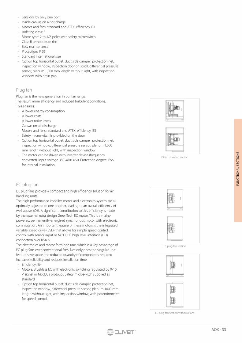
Plug fanPlug fan is the new generation in our fan range. The result: more efficiency and reduced turbulent conditions. This ensures:
• A lower energy consumption• A lower costs• A lower noise levels• Canvas on air discharge• Motors and fans : standard and ATEX, efficiency IE3• Safety microswitch is provided on the door• Option top horizontal outlet: duct side damper, protection net,
inspection window, differential pressure sensor, plenum 1,000 mm length without light, with inspection window
• The motor can be driven with inverter device (frequency converter). Input voltage 380-480/3/50. Protection degree IP55, for internal installation.
EC plug fanEC plug fans provide a compact and high efficiency solution for air handling units. The high performance impeller, motor and electronics system are all optimally adjusted to one another, leading to an overall efficiency of well above 60%. A significant contribution to this efficiency is made by the external rotor design GreenTech EC motor. This is a mains-powered, permanently-energised synchronous motor with electronic commutation. An important feature of these motors is the integrated variable speed drive (VSD) that allows for simple speed control, control with sensor input or MODBUS high level interface (HLI) connection over RS485.The electronics and motor form one unit, which is a key advantage of EC plug fans over conventional fans. Not only does the singular unit feature save space, the reduced quantity of components required increases reliability and reduces installation time.
• Efficiency: IE4• Motors: Brushless EC with electronic switching regulated by 0-10
V signal or ModBus protocol. Safety microswitch supplied as standard.
• Option top horizontal outlet: duct side damper, protection net, Inspection window, differential pressure sensor, plenum 1000 mm length without light, with inspection window, with potentiometer for speed control.
Direct drive fan section
EC plug fan section
EC plug fan section with two fans
34 - AQX
Section with steam generator Diffusion system
Indirect steam with external boiler
Range of indirect steam Detail humidifier control
Electrodes air humidifier section
Steam humidifier section
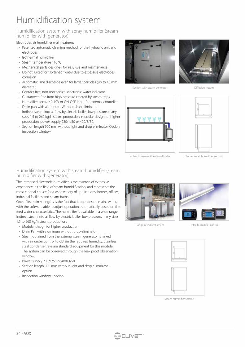
Humidification systemHumidification system with spray humidifier (steam humidifier with generator)Electrodes air humidifier main features:
• Patented automatic cleaning method for the hydraulic unit and electrodes
• Isothermal humidifier• Steam temperature 110 °C• Mechanical parts designed for easy use and maintenance• Do not suited for "softened" water due to excessive electrodes
corrosion• Automatic lime discharge even for larger particles (up to 40 mm
diameter)• Contact-free, non-mechanical electronic water indicator• Guaranteed free from high pressure created by steam traps • Humidifier control: 0-10V or ON-OFF input for external controller• Drain pan with aluminum. Without drop eliminator• Indirect steam into airflow by electric boiler, low pressure, many
sizes 1.5 to 260 kg/h steam production, modular design for higher production, power supply 230/1/50 or 400/3/50.
• Section length 900 mm without light and drop eliminator. Option inspection window.
Humidification system with steam humidifier (steam humidifier with generator)The immersed electrode humidifier is the essence of extensive experience in the field of steam humidification, and represents the most rational choice for a wide variety of applications: homes, offices, industrial facilities and steam baths.One of its main strengths is the fact that it operates on mains water, with the software able to adjust operation automatically based on the feed water characteristics. The humidifier is available in a wide range.Indirect steam into airflow by electric boiler, low pressure, many sizes 1.5 to 260 kg/h steam production.
• Modular design for higher production• Drain Pan with aluminum without drop eliminator• Steam obtained from the external steam generator is mixed
with air under control to obtain the required humidity. Stainless steel condense trays are standard equipment for this module. The system can be observed through the leak proof observation window.
• Power supply 230/1/50 or 400/3/50• Section length 900 mm without light and drop eliminator -
option• Inspection window - option

AQX - 35
FUN
CTI
ON
AL
SEC
TIO
NS
Honeycomb humidifier without pumpHoneycomb humidifier without pump
section
Honeycomb humidifier with pump Honeycomb humidifier with pump section
Description honeycomb pad
• High mechanical resistance• Ideal for unclean environments• High cooling efficiency• Reach compliant• Versatile and easy to replace• Algae, fungi and bacteria protection• UV - rays protection
Humidification system with honeycomb humidifierThe honeycomb humidifier section consists of a section housing, a honeycomb humidifier and a negative or positive pressure condensate drain siphon. It is also equipped with a double-wall inspection window and interior lighting (option). The honeycomb humidifier model is available with circulating water or with direct water.
Evaporative Cooler without internal pump• Structure • Double panel • Drain panel • Components • Innovative cellulose media treated with resin to stop biological
growth• Air saturation level = 16% better than a traditional cooling pad• Lower air pressure drop• Thickness 150 mm• Air saturation approximately 90%• Drop eliminator frame Al/PVC fins - 1 fold• Option with inspection window
Evaporative cooler with internal pump• Structure • Double panel • Drain panel • Components • Innovative cellulose media treated with resin to stop biological
growth• Air saturation level = 16% better than a traditional cooling pad• lower air pressure drop• Thickness 150 mm• Air saturation approximately 90%• Access door• Recirculation pump and floating valve• Drop eliminator frame Al/PVC fins - 1 fold• Option with inspection window
Honeycomb padOur “Cooling & Darkening” pad is characterized by a unique and patented “Double Elbow” shape of the channels, conceived in order to achieve higher cooling and humidification properties. This particular shape provides the panel with both an increased cooling efficiency and a darkening property, since it stops the light passage.The patented design of this new pad is the result of an innovative construction technology that provides it with exclusive features:
• Increased cooling efficiency (16% higher than traditional cooling pads) with a lower pressure drop.
• Total darkening to sunlight. • The cooling & darkening pad represents a very profit table
investment since it is cheaper than a system comprising a cooling pad with a separated light trap.
• Drain pan in aluminum.
36 - AQX
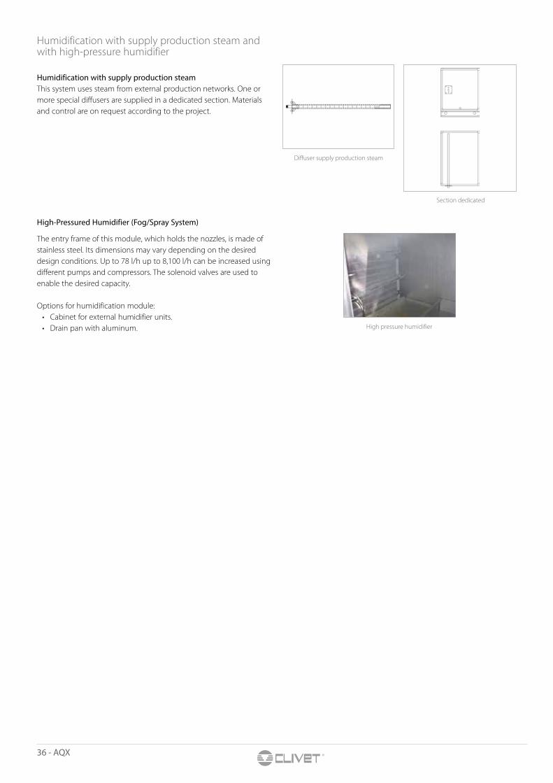
Diffuser supply production steam
Section dedicated
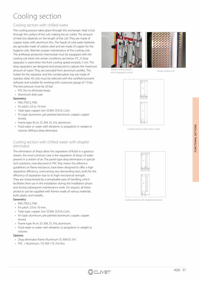
High pressure humidifier
Humidification with supply production steam and with high-pressure humidifier
Humidification with supply production steamThis system uses steam from external production networks. One or more special diffusers are supplied in a dedicated section. Materials and control are on request according to the project.
High-Pressured Humidifier (Fog/Spray System)
The entry frame of this module, which holds the nozzles, is made of stainless steel. Its dimensions may vary depending on the desired design conditions. Up to 78 l/h up to 8,100 l/h can be increased using different pumps and compressors. The solenoid valves are used to enable the desired capacity.
Options for humidification module: • Cabinet for external humidifier units. • Drain pan with aluminum.
AQX - 37
FUN
CTI
ON
AL
SEC
TIO
NS
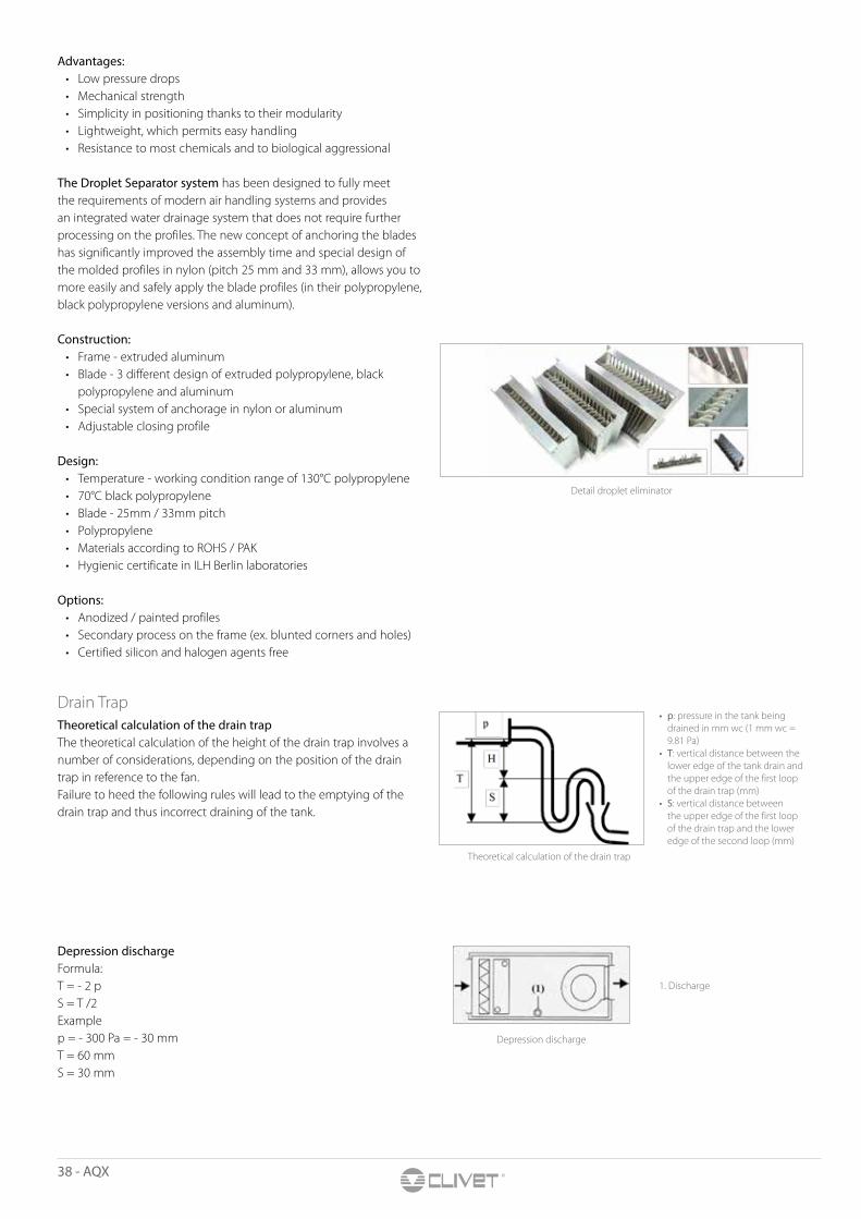
Detail cooling section with integrated control
Detail cooling coil
Cooling section with water cooler
Cooling section with droplet eliminator
Cooling sectionCooling section with chilled waterThe cooling process takes place through this exchanger. Heat is lost through the surface of the coil, making the air colder. The amount of heat lost depends on the length of the coil. They are made of copper tubes with aluminum fins. The heads of cold water batteries are generally made of carbon steel and are made of copper for the hygiene coils. Maintain proper maintenance of the cooling coils. The antifreeze protection thermostat must be equipped with the cooling coil when the winter conditions are below 5°C. A drop separator is used when the front cooling speed exceeds 2 m/s. The drop separators are designed and produced to capture the maximum amount of water. They are extruded from aluminum profiles. The holder for the separator and the condensation tray are made of stainless steel. All coils must be selected with the certified Eurovent software and suitable for working with a pressure gauge of 13 bar. The test pressure must be 20 bar.
• PVC fins to eliminate drops • Aluminum drain pan
Geometry: • P60, P3012, P40. • Fin pitch: 2.0 to 10 mm. • Tube type: copper, iron SS304, SS316, CuSn. • Fin type: aluminum, pre painted aluminum, copper, copper
tinned. • Frame type: fe zn, SS 304, SS 316, aluminum.• Fluid water or water with ethylenic or propylenic in weight or
volume. Without drop eliminator.
Cooling section with chilled water with droplet eliminatorThe eliminators of drops allow the separation of fluids in a gaseous stream, the most common case is the separation of drops of water present in a stream of air. The panel-type drop eliminators in special tech-solutions, manufactured in PVC that meets the reference guidelines on flame resistance, have been designed to offer a high separation efficiency, overcoming very demanding tests, both for the efficiency of separation due to its high mechanical strength.They are characterized by a remarkable ease of handling, which facilitates their use in the installation during the installation phase and during subsequent maintenance work. On request, all these products can be supplied with frames made of various materials, both plastic and metallic.Geometry:
• P60, P3012, P40.• Fin pitch: 2.0 to 10 mm. • Tube type: copper, iron SS304, SS316, CuSn. • Fin type: aluminum, pre painted aluminum, copper, copper
tinned. • Frame type: fe zn, SS 304, SS 316, aluminum. • Fluid water or water with ethylenic or propylenic in weight or
volume. Options:
• Drop eliminator frame Aluminum SS 304/SS 316 • PVC / Aluminum / SS 304 / SS 316 fins.
38 - AQX
Detail droplet eliminator
Theoretical calculation of the drain trap
Depression discharge
• p: pressure in the tank being drained in mm wc (1 mm wc = 9.81 Pa)
• T: vertical distance between the lower edge of the tank drain and the upper edge of the first loop of the drain trap (mm)
• S: vertical distance between the upper edge of the first loop of the drain trap and the lower edge of the second loop (mm)
1. Discharge
Advantages:• Low pressure drops • Mechanical strength• Simplicity in positioning thanks to their modularity • Lightweight, which permits easy handling • Resistance to most chemicals and to biological aggressional
The Droplet Separator system has been designed to fully meet the requirements of modern air handling systems and provides an integrated water drainage system that does not require further processing on the profiles. The new concept of anchoring the blades has significantly improved the assembly time and special design of the molded profiles in nylon (pitch 25 mm and 33 mm), allows you to more easily and safely apply the blade profiles (in their polypropylene, black polypropylene versions and aluminum). Construction:
• Frame - extruded aluminum• Blade - 3 different design of extruded polypropylene, black
polypropylene and aluminum • Special system of anchorage in nylon or aluminum• Adjustable closing profile
Design:• Temperature - working condition range of 130°C polypropylene • 70°C black polypropylene• Blade - 25mm / 33mm pitch• Polypropylene• Materials according to ROHS / PAK• Hygienic certificate in ILH Berlin laboratories
Options:
• Anodized / painted profiles• Secondary process on the frame (ex. blunted corners and holes)• Certified silicon and halogen agents free
Drain Trap Theoretical calculation of the drain trapThe theoretical calculation of the height of the drain trap involves a number of considerations, depending on the position of the drain trap in reference to the fan.Failure to heed the following rules will lead to the emptying of the drain trap and thus incorrect draining of the tank.
Depression dischargeFormula:T = - 2 pS = T /2Examplep = - 300 Pa = - 30 mm T = 60 mmS = 30 mm
AQX - 39
FUN
CTI
ON
AL
SEC
TIO
NS
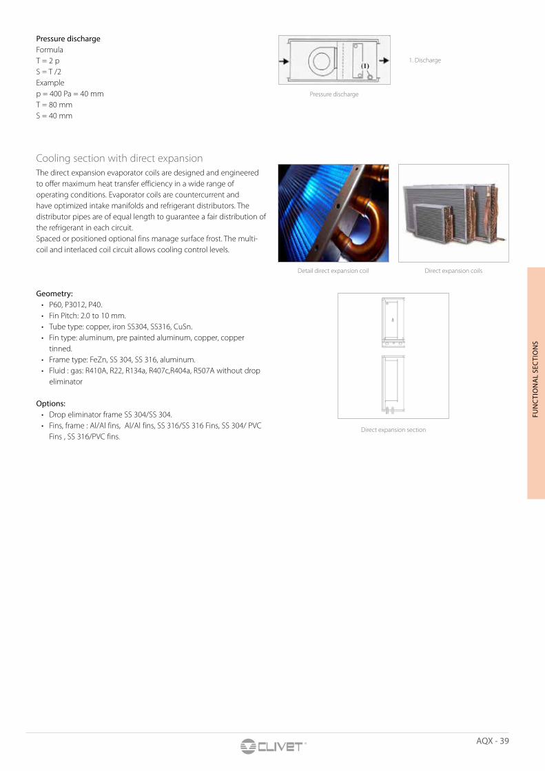
Detail direct expansion coil Direct expansion coils
Direct expansion section
Pressure discharge
1. Discharge
Pressure dischargeFormula T = 2 pS = T /2Example p = 400 Pa = 40 mmT = 80 mmS = 40 mm
Cooling section with direct expansionThe direct expansion evaporator coils are designed and engineered to offer maximum heat transfer efficiency in a wide range of operating conditions. Evaporator coils are countercurrent and have optimized intake manifolds and refrigerant distributors. The distributor pipes are of equal length to guarantee a fair distribution of the refrigerant in each circuit.Spaced or positioned optional fins manage surface frost. The multi-coil and interlaced coil circuit allows cooling control levels.
Geometry: • P60, P3012, P40. • Fin Pitch: 2.0 to 10 mm. • Tube type: copper, iron SS304, SS316, CuSn. • Fin type: aluminum, pre painted aluminum, copper, copper
tinned. • Frame type: FeZn, SS 304, SS 316, aluminum. • Fluid : gas: R410A, R22, R134a, R407c,R404a, R507A without drop
eliminator Options:
• Drop eliminator frame SS 304/SS 304.• Fins, frame : Al/Al fins, Al/Al fins, SS 316/SS 316 Fins, SS 304/ PVC
Fins , SS 316/PVC fins.
40 - AQX
Heat recovery section with plate recuperator
Detail plate recuperator Detail recuperator with by-pass
Detail recuperator in parallel
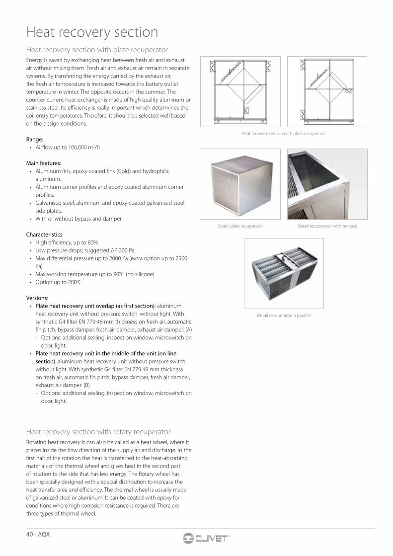
Heat recovery sectionHeat recovery section with plate recuperatorEnergy is saved by exchanging heat between fresh air and exhaust air without mixing them. Fresh air and exhaust air remain in separate systems. By transferring the energy carried by the exhaust air, the fresh air temperature is increased towards the battery outlet temperature in winter. The opposite occurs in the summer. The counter-current heat exchanger is made of high quality aluminum or stainless steel. Its efficiency is really important which determines the coil entry temperatures. Therefore, it should be selected well based on the design conditions.
Range:• Airflow up to 100,000 m3/h
Main features:• Aluminum fins, epoxy coated fins (Gold) and hydrophilic
aluminum.• Aluminum corner profiles and epoxy coated aluminum corner
profiles. • Galvanised steel, aluminum and epoxy coated galvanised steel
side plates.• With or without bypass and damper
Characteristics:• High efficiency, up to 80%• Low pressure drops; suggested ΔP 200 Pa.• Max differential pressure up to 2000 Pa (extra option up to 2500
Pa)• Max working temperature up to 90°C (no silicone)• Option up to 200°C
Versions:• Plate heat recovery unit overlap (as first section): aluminum
heat recovery unit without pressure switch, without light. With synthetic G4 filter EN 779 48 mm thickness on fresh air, automatic fin pitch, bypass damper, fresh air damper, exhaust air damper. (A) - Options: additional sealing, inspection window, microswitch on
door, light.• Plate heat recovery unit in the middle of the unit (on line
section): aluminum heat recovery unit without pressure switch, without light. With synthetic G4 filter EN 779 48 mm thickness on fresh air, automatic fin pitch, bypass damper, fresh air damper, exhaust air damper. (B) - Options: additional sealing, inspection window, microswitch on
door, light.
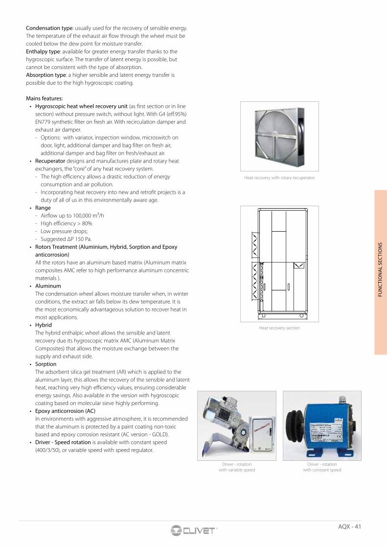
Heat recovery section with rotary recuperatorRotating heat recovery It can also be called as a heat wheel, where it places inside the flow direction of the supply air and discharge. In the first half of the rotation the heat is transferred to the heat-absorbing materials of the thermal wheel and gives heat in the second part of rotation to the side that has less energy. The Rotary wheel has been specially designed with a special distribution to increase the heat transfer area and efficiency. The thermal wheel is usually made of galvanized steel or aluminum. It can be coated with epoxy for conditions where high corrosion resistance is required. There are three types of thermal wheel.
AQX - 41
FUN
CTI
ON
AL
SEC
TIO
NS
Heat recovery with rotary recuperator
Heat recovery section
Driver - rotation with constant speed
Driver - rotation with variable speed
Condensation type: usually used for the recovery of sensible energy. The temperature of the exhaust air flow through the wheel must be cooled below the dew point for moisture transfer. Enthalpy type: available for greater energy transfer thanks to the hygroscopic surface. The transfer of latent energy is possible, but cannot be consistent with the type of absorption. Absorption type: a higher sensible and latent energy transfer is possible due to the high hygroscopic coating.
Mains features:• Hygroscopic heat wheel recovery unit (as first section or in line
section) without pressure switch, without light. With G4 (eff.95%) EN779 synthetic filter on fresh air. With recirculation damper and exhaust air damper. - Options: with variator, inspection window, microswitch on
door, light, additional damper and bag filter on fresh air, additional damper and bag filter on fresh/exhaust air.
• Recuperator designs and manufactures plate and rotary heat exchangers, the “core” of any heat recovery system. - The high efficiency allows a drastic reduction of energy
consumption and air pollution. - Incorporating heat recovery into new and retrofit projects is a
duty of all of us in this environmentally aware age.• Range
- Airflow up to 100,000 m³/h - High efficiency > 80% - Low pressure drops; - Suggested ΔP 150 Pa.
• Rotors Treatment (Aluminium, Hybrid, Sorption and Epoxy anticorrosion) All the rotors have an aluminum based matrix (Aluminum matrix composites AMC refer to high performance aluminum concentric materials ).
• Aluminum The condensation wheel allows moisture transfer when, in winter conditions, the extract air falls below its dew temperature. It is the most economically advantageous solution to recover heat in most applications.
• Hybrid The hybrid enthalpic wheel allows the sensible and latent recovery due its hygroscopic matrix AMC (Aluminum Matrix Composites) that allows the moisture exchange between the supply and exhaust side.
• Sorption The adsorbent silica gel treatment (AR) which is applied to the aluminum layer, this allows the recovery of the sensible and latent heat, reaching very high efficiency values, ensuring considerable energy savings. Also available in the version with hygroscopic coating based on molecular sieve highly performing.
• Epoxy anticorrosion (AC) In environments with aggressive atmosphere, it is recommended that the aluminum is protected by a paint coating non-toxic based and epoxy corrosion resistant (AC version - GOLD).
• Driver - Speed rotation is available with constant speed (400/3/50), or variable speed with speed regulator.
42 - AQX
E.P.
Detail AQX with heat recovery section between fresh air and exhaust air
Detail AQX with heat recovery section with fin recuperator
Outdoor unit AQX - detail
Base frame AQX - detailDetail 2-inch lifting holes and particular
design section
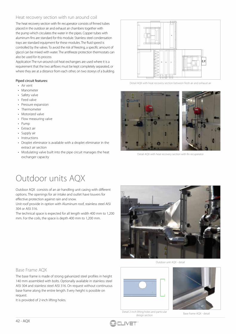
Heat recovery section with run around coilThe heat recovery section with fin recuperator consists of finned tubes placed in the outdoor air and exhaust air chambers together with the pump which circulates the water in the pipes. Copper tubes with aluminum fins are standard for this module. Stainless steel condensation trays are standard equipment for these modules. The fluid speed is controlled by the valves. To avoid the risk of freezing, a specific amount of glycol can be mixed with water. The antifreeze protection thermostats can also be used for its processApplication The run-around coil heat exchangers are used where it is a requirement that the two airflows must be kept completely separated, or where they are at a distance from each other, on two storeys of a building.
Piped circuit features:• Air vent• Manometer• Safety valve• Feed valve• Pressure expansion• Thermometer• Motorized valve• Flow measuring valve• Pump• Extract air• Supply air• Instructions• Droplet eliminator is available with a droplet eliminator in the
extract air section• Modulating valve built into the pipe circuit manages the heat
exchanger capacity
Outdoor units AQX Outdoor AQX consists of an air handling unit casing with different options. The openings for air intake and outlet have louvers for effective protection against rain and snow.Unit roof provide in option with Aluminum roof, stainless steel AISI 304 or AISI 316.The technical space is expected for all length width 400 mm to 1,200 mm. For the coils, the space is depth 400 mm to 1,200 mm.
Base Frame AQX The base frame is made of strong galvanized steel profiles in height 140 mm assembled with bolts. Optionally available in stainless steel AISI 304 and stainless steel AISI 316. On request without continuous base frame along the entire length. Every height is possible on request.It is provided of 2-inch lifting holes.
AQX - 43
FUN
CTI
ON
AL
SEC
TIO
NS
Sound attenuation section
Sound attenuator module
Detail soundproofing section
Inspection section Detail door and handle
Flexible duct connectionDuct connection
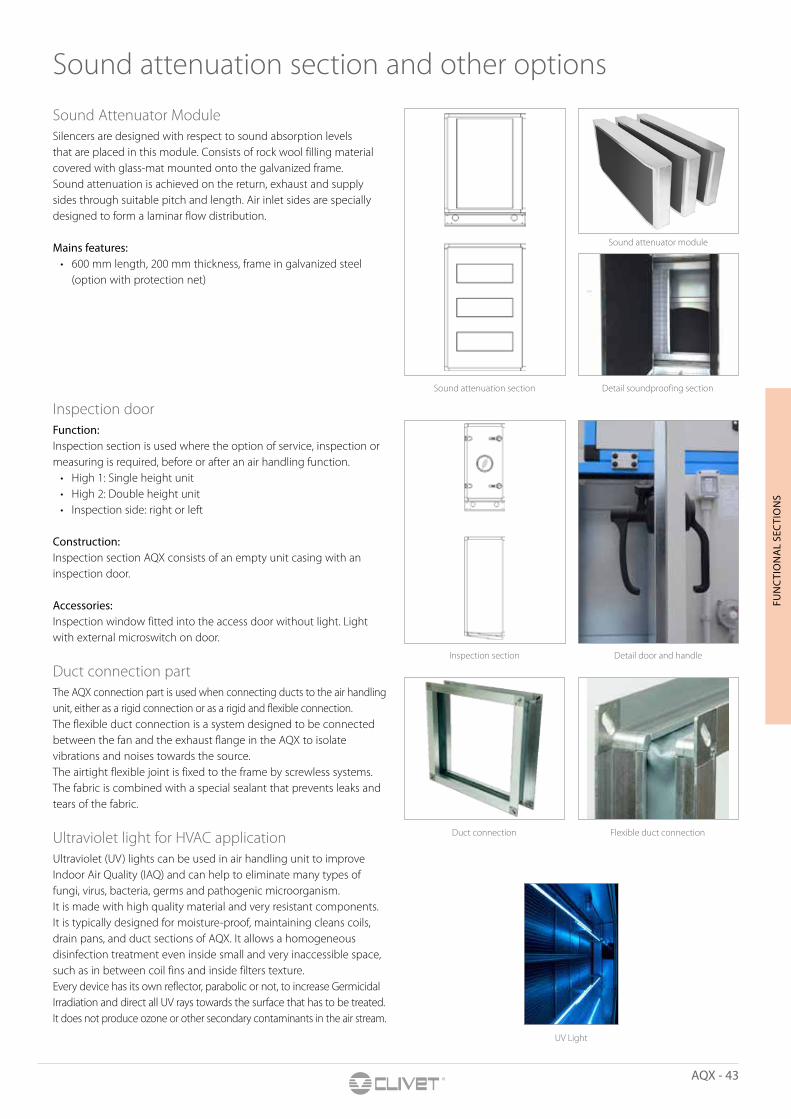
Sound Attenuator Module Silencers are designed with respect to sound absorption levels that are placed in this module. Consists of rock wool filling material covered with glass-mat mounted onto the galvanized frame. Sound attenuation is achieved on the return, exhaust and supply sides through suitable pitch and length. Air inlet sides are specially designed to form a laminar flow distribution.
Mains features: • 600 mm length, 200 mm thickness, frame in galvanized steel
(option with protection net)
Inspection door Function:Inspection section is used where the option of service, inspection or measuring is required, before or after an air handling function.
• High 1: Single height unit• High 2: Double height unit• Inspection side: right or left
Construction: Inspection section AQX consists of an empty unit casing with an inspection door.
Accessories: Inspection window fitted into the access door without light. Light with external microswitch on door.
Duct connection part The AQX connection part is used when connecting ducts to the air handling unit, either as a rigid connection or as a rigid and flexible connection.The flexible duct connection is a system designed to be connected between the fan and the exhaust flange in the AQX to isolate vibrations and noises towards the source.The airtight flexible joint is fixed to the frame by screwless systems. The fabric is combined with a special sealant that prevents leaks and tears of the fabric.
Ultraviolet light for HVAC applicationUltraviolet (UV) lights can be used in air handling unit to improve Indoor Air Quality (IAQ) and can help to eliminate many types of fungi, virus, bacteria, germs and pathogenic microorganism.It is made with high quality material and very resistant components. It is typically designed for moisture-proof, maintaining cleans coils, drain pans, and duct sections of AQX. It allows a homogeneous disinfection treatment even inside small and very inaccessible space, such as in between coil fins and inside filters texture.Every device has its own reflector, parabolic or not, to increase Germicidal Irradiation and direct all UV rays towards the surface that has to be treated.It does not produce ozone or other secondary contaminants in the air stream.
Sound attenuation section and other options
UV Light
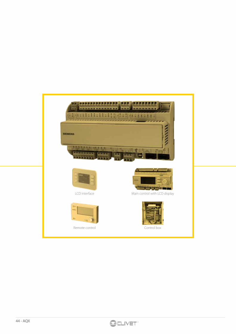
44 - AQX
LCD interface Main control with LCD display
Remote control Control box
AQX - 45
Control system
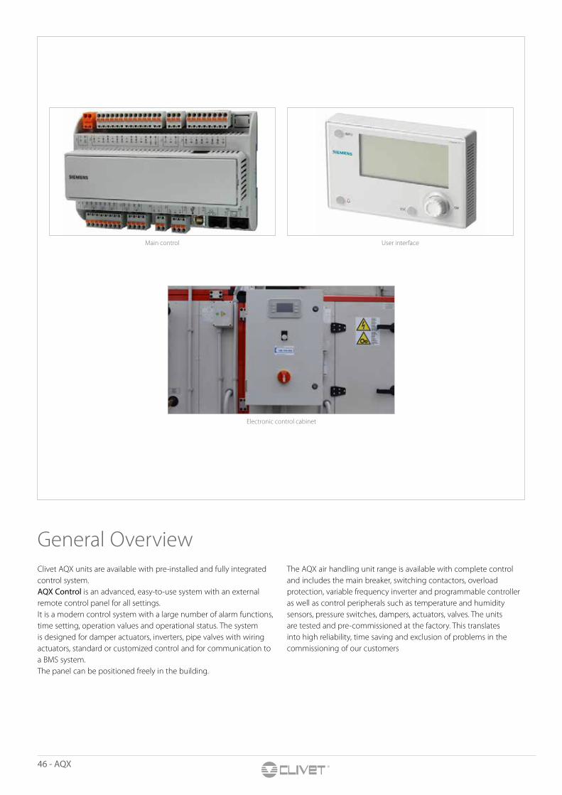
46 - AQX
General OverviewClivet AQX units are available with pre-installed and fully integrated control system. AQX Control is an advanced, easy-to-use system with an external remote control panel for all settings. It is a modern control system with a large number of alarm functions, time setting, operation values and operational status. The system is designed for damper actuators, inverters, pipe valves with wiring actuators, standard or customized control and for communication to a BMS system.The panel can be positioned freely in the building.
The AQX air handling unit range is available with complete control and includes the main breaker, switching contactors, overload protection, variable frequency inverter and programmable controller as well as control peripherals such as temperature and humidity sensors, pressure switches, dampers, actuators, valves. The units are tested and pre-commissioned at the factory. This translates into high reliability, time saving and exclusion of problems in the commissioning of our customers
Electronic control cabinet
User interfaceMain control
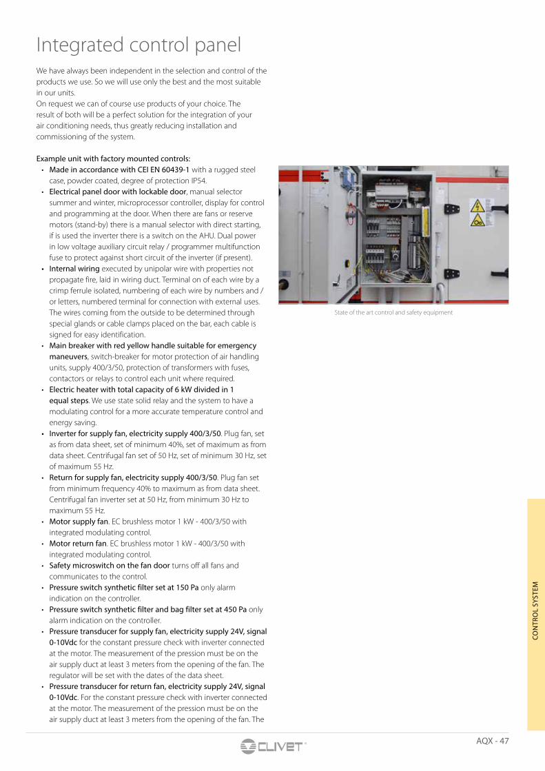
AQX - 47
CON
TRO
L SY
STEM
State of the art control and safety equipment
Integrated control panel We have always been independent in the selection and control of the products we use. So we will use only the best and the most suitable in our units.On request we can of course use products of your choice. The result of both will be a perfect solution for the integration of your air conditioning needs, thus greatly reducing installation and commissioning of the system.
Example unit with factory mounted controls: • Made in accordance with CEI EN 60439-1 with a rugged steel
case, powder coated, degree of protection IP54. • Electrical panel door with lockable door, manual selector
summer and winter, microprocessor controller, display for control and programming at the door. When there are fans or reserve motors (stand-by) there is a manual selector with direct starting, if is used the inverter there is a switch on the AHU. Dual power in low voltage auxiliary circuit relay / programmer multifunction fuse to protect against short circuit of the inverter (if present).
• Internal wiring executed by unipolar wire with properties not propagate fire, laid in wiring duct. Terminal on of each wire by a crimp ferrule isolated, numbering of each wire by numbers and / or letters, numbered terminal for connection with external uses. The wires coming from the outside to be determined through special glands or cable clamps placed on the bar, each cable is signed for easy identification.
• Main breaker with red yellow handle suitable for emergency maneuvers, switch-breaker for motor protection of air handling units, supply 400/3/50, protection of transformers with fuses, contactors or relays to control each unit where required.
• Electric heater with total capacity of 6 kW divided in 1 equal steps. We use state solid relay and the system to have a modulating control for a more accurate temperature control and energy saving.
• Inverter for supply fan, electricity supply 400/3/50. Plug fan, set as from data sheet, set of minimum 40%, set of maximum as from data sheet. Centrifugal fan set of 50 Hz, set of minimum 30 Hz, set of maximum 55 Hz.
• Return for supply fan, electricity supply 400/3/50. Plug fan set from minimum frequency 40% to maximum as from data sheet. Centrifugal fan inverter set at 50 Hz, from minimum 30 Hz to maximum 55 Hz.
• Motor supply fan. EC brushless motor 1 kW - 400/3/50 with integrated modulating control.
• Motor return fan. EC brushless motor 1 kW - 400/3/50 with integrated modulating control.
• Safety microswitch on the fan door turns off all fans and communicates to the control.
• Pressure switch synthetic filter set at 150 Pa only alarm indication on the controller.
• Pressure switch synthetic filter and bag filter set at 450 Pa only alarm indication on the controller.
• Pressure transducer for supply fan, electricity supply 24V, signal 0-10Vdc for the constant pressure check with inverter connected at the motor. The measurement of the pression must be on the air supply duct at least 3 meters from the opening of the fan. The regulator will be set with the dates of the data sheet.
• Pressure transducer for return fan, electricity supply 24V, signal 0-10Vdc. For the constant pressure check with inverter connected at the motor. The measurement of the pression must be on the air supply duct at least 3 meters from the opening of the fan. The

48 - AQX
Management scheme
regulator will be set with the dates of the data sheet. • Return air damper actuator ON-OFF, electricity supply 24Volt.
When the AHU is turn on the damper is opened. When the AHU is turned off the damper is closed.
• Fresh air damper actuator ON-OFF, electricity supply 24 Volt. When the AHU is turn on the damper is opened. When the AHU is turned off the damper is closed.
• Antifreeze thermostat, signal ON-OFF. It works only in winter with set point of 5°C default. In case of intervention it turn off the fan, it closes damper and it opens the heating valve at the 100%.
• Temperature probe outdoor air signal NTC (to use only with 3 damper, plate heat recovery, only by pass damper or recirculation damper, heat wheel recovery unit) it works only in the summer for the free cooling.
• Temperature proof maximum and minimum limit, signal NTC. The default minimum limit is 16°C and the default maximum limit is 50°C. In winter acts on the heating coil according to the minimum limit (opening the valve, giving more power to the electric heater or starting the heat pump) and the maximum (closing the valve, giving less power to the electric heater or stopping the heat pump). In summer acts on the cooling coil according only to the minimum limit closing the valve or stopping the condensing unit. The minimum temperature for the minimum limit set point is 10°C. The maximum temperature for the maximum limit set point is 150°C.
• Standard or customized control: a compact control with standard management of main options, such as damper, fan, and actuator on valve ready to use. It is the cheapest solution to control AQX. A customized control can be provided to achieve all needs of a specific application or a special execution.
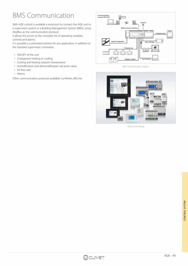
AQX - 49
CON
TRO
L SY
STEM
BMS Communication System
AQX control family
BMS Communication With AQX control is available a serial port to connect the AQX unit to a supervision system or a Building Management System (BMS), using ModBus as the communication protocol.It allows the access to the complete list of operating variables, controls and alarms.It is possible a customized solution for any application, in addition to the standard supervision command:
• ON/OFF of the unit• Changeover heating or cooling• Cooling and heating setpoint temperature • Humidification and dehumidification set point value• Air flow rate• Alarms
Other communication protocols available: LonWorks, BACnet.
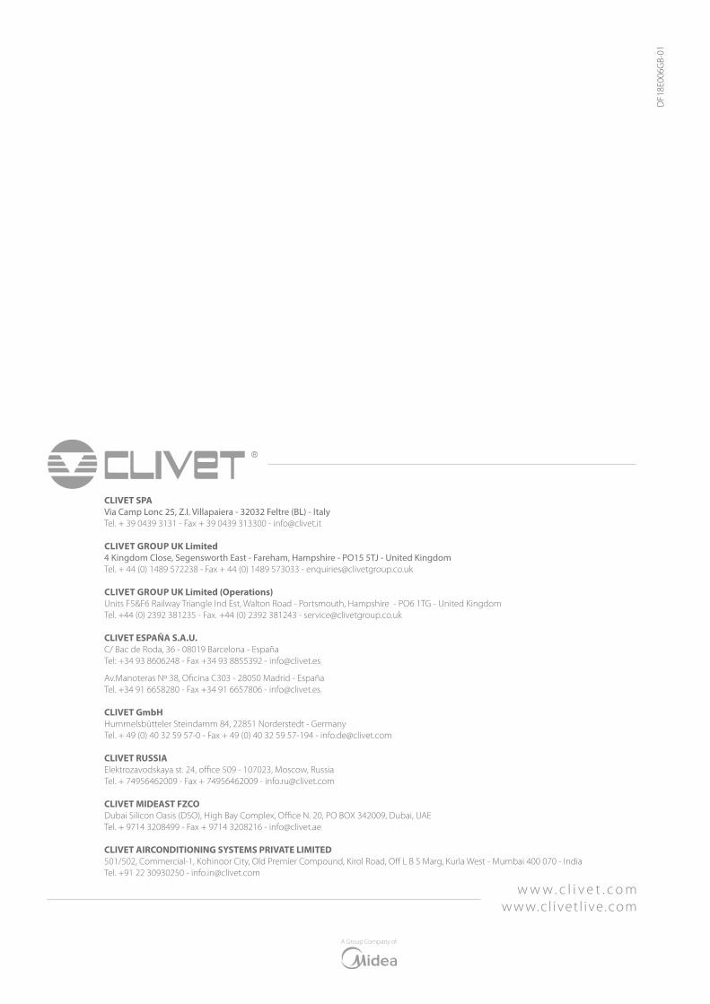
CLIVET SPAVia Camp Lonc 25, Z.I. Villapaiera - 32032 Feltre (BL) - Italy Tel. + 39 0439 3131 - Fax + 39 0439 313300 - [email protected]
CLIVET GROUP UK Limited4 Kingdom Close, Segensworth East - Fareham, Hampshire - PO15 5TJ - United KingdomTel. + 44 (0) 1489 572238 - Fax + 44 (0) 1489 573033 - [email protected]
CLIVET GROUP UK Limited (Operations)Units F5&F6 Railway Triangle Ind Est, Walton Road - Portsmouth, Hampshire - PO6 1TG - United KingdomTel. +44 (0) 2392 381235 - Fax. +44 (0) 2392 381243 - [email protected]
CLIVET ESPAÑA S.A.U.C/ Bac de Roda, 36 - 08019 Barcelona - EspañaTel: +34 93 8606248 - Fax +34 93 8855392 - [email protected]
Av.Manoteras Nº 38, Oficina C303 - 28050 Madrid - EspañaTel. +34 91 6658280 - Fax +34 91 6657806 - [email protected]
CLIVET GmbHHummelsbütteler Steindamm 84, 22851 Norderstedt - GermanyTel. + 49 (0) 40 32 59 57-0 - Fax + 49 (0) 40 32 59 57-194 - [email protected]
CLIVET RUSSIA Elektrozavodskaya st. 24, office 509 - 107023, Moscow, RussiaTel. + 74956462009 - Fax + 74956462009 - [email protected]
CLIVET MIDEAST FZCODubai Silicon Oasis (DSO), High Bay Complex, Office N. 20, PO BOX 342009, Dubai, UAE Tel. + 9714 3208499 - Fax + 9714 3208216 - [email protected]
CLIVET AIRCONDITIONING SYSTEMS PRIVATE LIMITED501/502, Commercial-1, Kohinoor City, Old Premier Compound, Kirol Road, Off L B S Marg, Kurla West - Mumbai 400 070 - IndiaTel. +91 22 30930250 - [email protected]
w w w . c l i v e t . c o mwww.c l ivet l ive .com
A Group Company of
DF1
8E00
6GB-
01