aquifer test implementation - bill - srbcmdw.srbc.net/pwsap/spring2016workshops/assets/docs... ·...
TRANSCRIPT
AQUIFER TEST IMPLEMENTATION BILL MILLER, P.G.
SUSQUEHANNA RIVER BASIN COMMISSION

AQUIFER TEST IMPLEMENTATION
Once your Aquifer Test Plan is approved…
Usually two years to complete the aquifer test
The majority of failed tests originate with implementation issues

Approved Aquifer Test Plan to Failed Aquifer Test…
Poor Execution of a Good Plan
Rigid Execution of a Good Plan under Changing Conditions
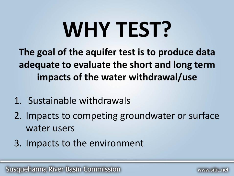
WHY TEST? The goal of the aquifer test is to produce data adequate to evaluate the short and long term
impacts of the water withdrawal/use
1. Sustainable withdrawals
2. Impacts to competing groundwater or surface water users
3. Impacts to the environment

The goal of the aquifer testing is the collection of appropriate data
NOT A task checklist
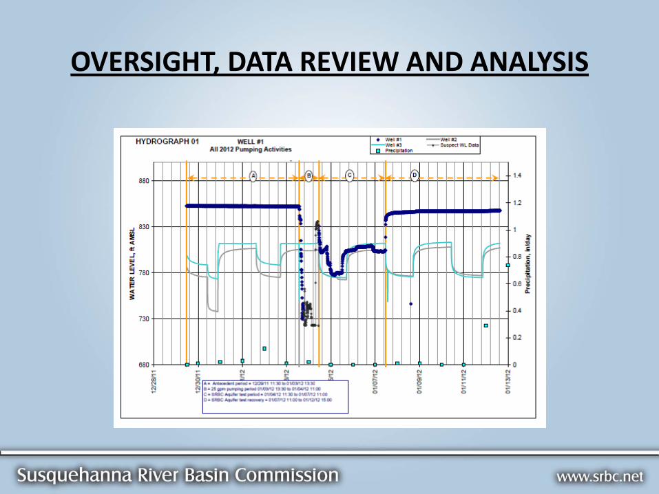
OVERSIGHT, DATA REVIEW AND ANALYSIS

DIRECT VS. INDIRECT MEASUREMENT
Where is that rating curve….

COMMUNICATION
Public Water System
Consultants
Regulatory Agency (SRBC/PADEP)

AQUIFER TESTING IMPLEMENTATION
Consultant should be the expert on the site
Suggested that consultants follow the format of the guidance
Minimize variables during testing – control everything that is controllable
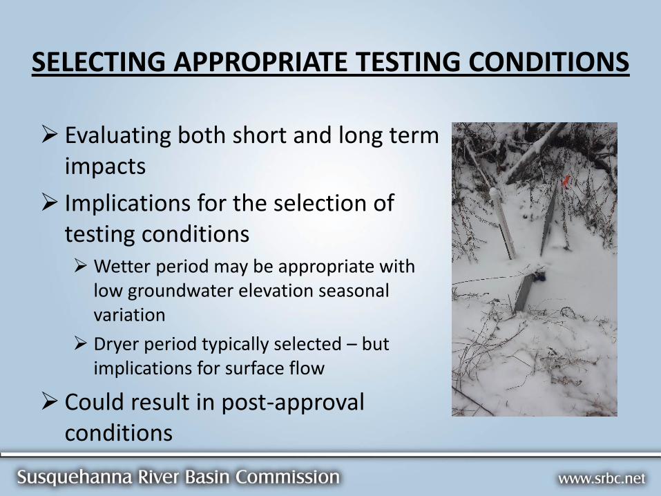
SELECTING APPROPRIATE TESTING CONDITIONS
Evaluating both short and long term impacts
Implications for the selection of testing conditions Wetter period may be appropriate with
low groundwater elevation seasonal variation
Dryer period typically selected – but implications for surface flow
Could result in post-approval conditions


AQUIFER TESTING IMPLEMENTATION
Master prognosticator
Finding testing window can be challenging
Monitoring network often in place collecting background data, waiting for opportunity to test
Look for periods with low probability for precipitation
During winter, consider the possibility of snowmelt
Weather.com; NOAA; Weather Underground; CoCoRaHS
Tests may be invalidated by too much precipitation
Surface water monitoring points tend to be most sensitive

Aquifer Testing
Step Test
Background Monitoring
Constant-Rate Aquifer Test
Recovery Test
STEP TEST
Only required if the proposed production well is to be used as one of the two points in a distance-drawdown analysis, but…
Can provide information that could be helpful during the constant-rate test
Well efficiency at various rates
Can be conducted in advance of the remainder of the testing
Select locations can be monitored to refine the monitoring network
The pumping may be continued at a selected rate to provide additional information

STEP TEST


BACKGROUND MONITORING
Begins after 90% recovery from step test
At least 48 hours (72-hours in PADEP guidance)
Demonstrate asymptotic groundwater and recessional surface water trends (base flow) in monitoring network prior to starting test
Additional background monitoring may be required for some projects (e.g. projects with other pumping wells)
No pumping of test well during background period.


CONSTANT-RATE AQUIFER TESTING
Begins immediately after background period
Assess sustainability
Evaluate the potential for adverse impacts
Predict impacts from long-term pumping

RECOVERY TEST
Immediately follows constant-rate test
At least 24-hours and until aquifer has recovered to at least 90% of pretest levels, minus groundwater recession
Useful in assessing sustainability of proposed withdrawal

GENERAL PERFORMANCE REQUIREMENTS

GENERAL PERFORMANCE REQUIREMENTS
A shorter duration test may be appropriate, particularly under changing conditions.
Test duration may need to be extended in response to test results and changing conditions (Monitor test results).
1. The generally recommended length of the aquifer constant-rate test is 72 hours. A longer or shorter test may be appropriate to evaluate aquifer and well capabilities, as well as potential impacts to existing water supplies and the environment. The project hydrogeologist must recommend an adequate pumping test length demonstrating due diligence for site characterization and long-term protection of the resource, and provide a rationale for that recommendation. However, the duration may need to be increased during the test in response to ongoing test results.

Extending Constant-Rate Test Duration
Test interruptions
Pump problems
Generator/power problems
Other Murphy’s Law considerations
Generally, test should be extended by the amount of time to re-establish the pumping level and drawdown trend.
Data review and analysis during testing.

GENERAL PERFORMANCE REQUIREMENTS
May result in extended constant-rate test duration
Development and turbidity issues can be evaluated during step testing
Data evaluation during testing
2. Aquifer tests must be performed on wells that are considered to be completed and fully developed. Wells exhibiting incomplete development characteristics (i.e., turbidity spikes or unexplained water level fluctuations) may require an extension of the pumping phase or retesting. In carbonate, unconsolidated, or deeply weathered formations, continuous turbidity monitoring will be necessary, and the proposed monitoring methodology should be described in the aquifer test plan. Wells exhibiting well development episodes during the testing must demonstrate development-free performance during the last 72 hours of testing.

GENERAL PERFORMANCE REQUIREMENTS
Inspect discharge pipe/hose at test start-up and periodically during the test.
Use appropriate energy dissipation devices at discharge point
3. Discharge from the proposed production well must be routed such that recirculation does not occur. This typically results in a discharge point 300 to 500 feet down dip (bedding, schistosity, etc.) from the proposed pumping well, but may be 2,000 feet or more in karst-prone carbonate formations. Recirculation will invalidate the test and will require retesting.


GENERAL PERFORMANCE REQUIREMENTS
4. Prior to discharging any wastewater, drilling wastes, or raw water from the proposed production well to any surface water feature, the project sponsor must first obtain any required approvals from the appropriate state or local water management or other agencies. The approval(s) must be forwarded to the Commission prior to the start of testing.
5. The background, pumping, and recovery phases of aquifer testing must be conducted during a period of asymptotic groundwater and surface water recession (base flow). The test should not be conducted during or shortly after a precipitation event that could result in a rapid change of water level or flow.
6. Following the step test, the aquifer must be 90 percent or more recovered prior to the start of the 48-hour background monitoring period.
7. The background monitoring must immediately precede the constant-rate test.

GENERAL PERFORMANCE REQUIREMENTS
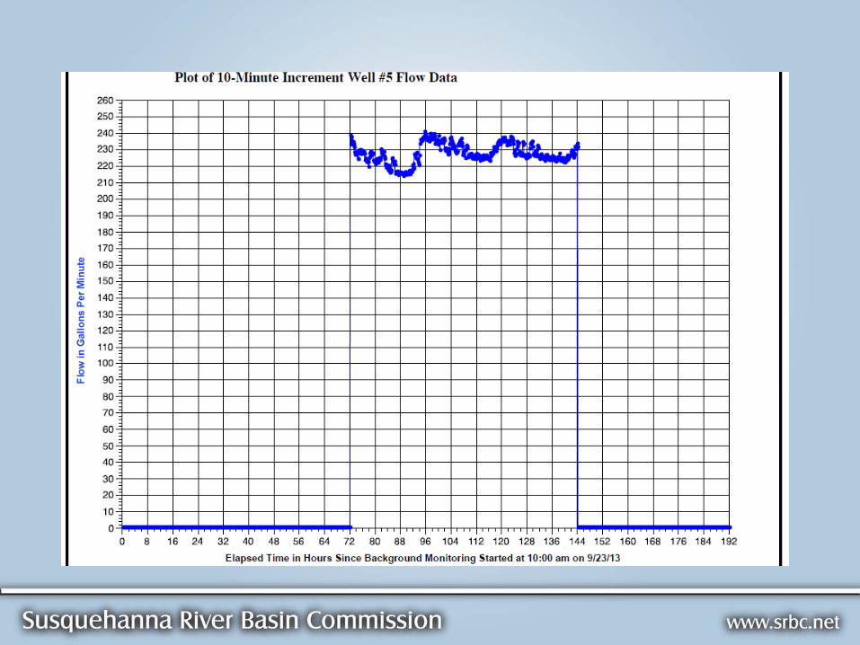
8. The proposed production well may be pumped at any rate desired, but must be pumped at a constant rate for the test duration specified in the approved plan (recommended 72 hours). The Commission will not approve the well for operation at a rate higher than the average tested rate.
9. The pumping rate of the proposed production well must be monitored with an appropriate flow measurement device that is accurate to within 5 percent. The flow rate should be held constant to within 5 percent of the target flow rate for the duration of the test or the test will likely not qualify as a constant-rate test and may have to be rerun.
10. Valving must allow adjustment of the pumping rate to within the required tolerances.
Make sure that the test is not started at maximum valve settings. Must be able to adjust to maintain rate with falling head.

5 % of the target flow rate
Considerations:
Under-developed well
Sustainable yield over-estimated based on blown yields
Step Tests can be very useful to refine target aquifer test rates
Pumping rate is one of the data trends that should be evaluated in addition to being documented.

SYSTEM OPERATION DURING TESTING
Refer to Aquifer Test Plan. Check implementation.
Communicate plans to all parties.
Communicate with SRBC staff if any changes are necessary.
Goal is to isolate impacts as a result of pumping the test well
Extended background periods may be needed to establish steady-state or near steady-state conditions
May be extremely important part of plan – often overlooked or not adequately considered

GENERAL PERFORMANCE REQUIREMENTS
11. The flow rate (gallons per minute) and cumulative flow (total gallons pumped) should be recorded at a minimum of once per hour.
12. All flow rate adjustments must be documented with a measurement of flow before and after adjustment, the time at which the adjustments were made, and a rationale for the adjustment. This information must be included in the hydrogeologic report.
GENERAL PERFORMANCE REQUIREMENTS
13. If a well exhibits unexpectedly excessive drawdown, testing should be suspended. After full recovery, the test should be restarted.
15. A test with a declining pumping rate due to excessive drawdown or inadequate pump capacity will be considered a failed test and will require retesting.
Monitor and evaluate during testing

GENERAL PERFORMANCE REQUIREMENTS
14. Any change in the trend of the time-drawdown curve, such as might be caused by a positive/recharge boundary or negative/barrier boundary encountered during the test, must have a record of at least 24 hours. Therefore, any boundary condition encountered during the last 24 hours of pumping will require that the test be extended.
GENERAL PERFORMANCE REQUIREMENTS
16. The aquifer test plan reviewer must be notified at least two working days prior to the start of testing by e-mail or telephone.
17. The project sponsor may be required, at its expense, to provide temporary water supply if an aquifer test results in interference with an existing water use.

GROUNDWATER MONITORING GUIDANCE
Don’t request that wells in use change their usage patterns. Groundwater elevation data still useful and can also be used to better evaluate impacts to other wells.
Monitoring devices

AUTOMATIC WATER RECORDERS (PRESSURE TRANSDUCERS)
Two cable types – vented and unvented.
Vented – Make sure to use desiccants. Install with end connection pointing downward so water does not collect and migrate down vent line.
Unvented – Sealed, so no condensation/water issues, but a barometric transducer MUST also be used. Barometric compensation MUST be conducted for any submitted data.
They can and do fail. ALWAYS collect manual back-up measurements.

AUTOMATIC WATER RECORDERS (PRESSURE TRANSDUCERS)
Operation of transducers should be verified prior to background monitoring and then rechecked prior to the constant-rate test.
Check battery levels
Check units and test programming
Transducers should be downloaded and data evaluated during testing phases. Direct read cables are recommended.
Any time a transducer is deployed, disturbed or removed, a manual measurement should be collected before and afterwards.

AUTOMATIC WATER RECORDERS (PRESSURE TRANSDUCERS)
Select appropriate PSI ratings
Install to monitor expected groundwater range
If groundwater level falls below transducer, the transducer should be lowered – again, collect a manual measurement before and after adjustment.
Installation of a stilling tube can dampen pump effects and ease deployment and retrieval.

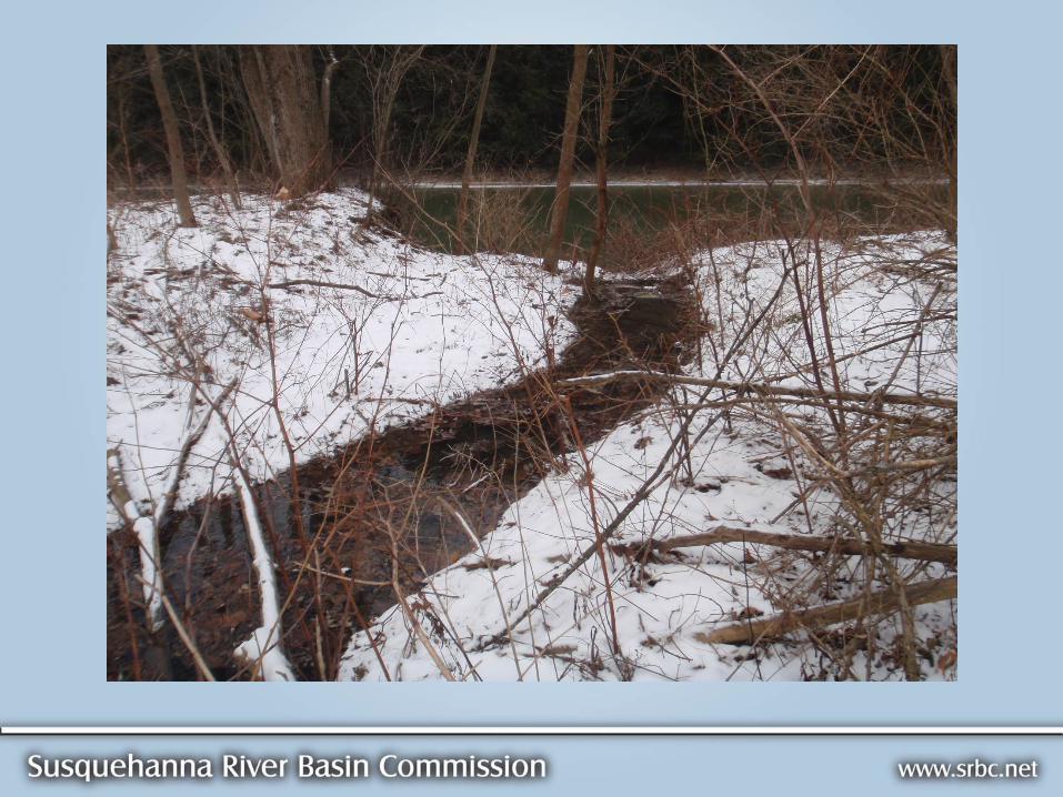
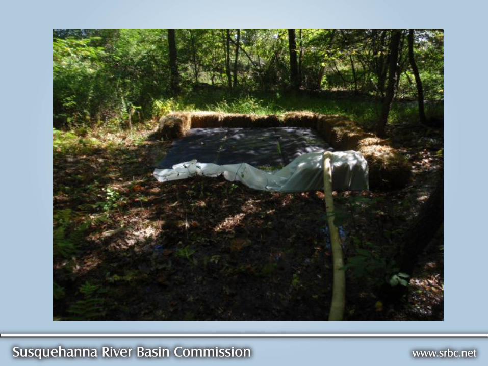
SURFACE WATER MONITORING GUIDANCE
Ponds and wetlands without flow:
Install hydraulically separated piezometers
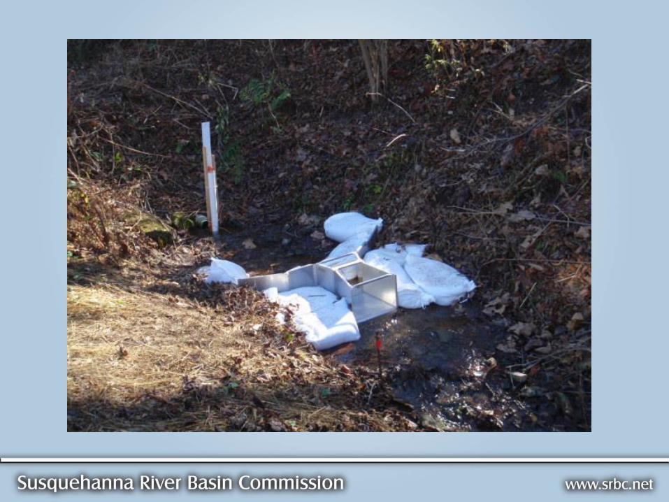
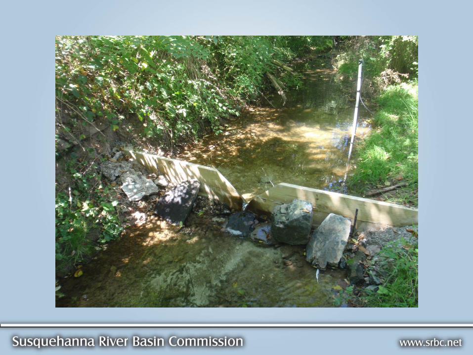
Flowing surface water (including pond and wetlands discharges as well as springs and streams)
Quantitative analysis (instrumented weir or flume) when the proposed withdrawal exceeds 10% of the flow at the time of testing (DIRECT MEASUREMENT)
Streambank piezometers may be used when the proposed withdrawal rate is less than 10% of the flow at the time of testing (INDIRECT MEASUREMENT)

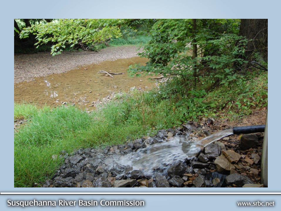
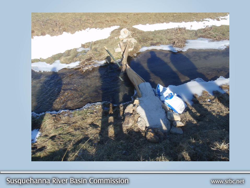
WEIRS AND FLUMES
Reliable measure of 10% of the proposed withdrawal or natural flow rate, whichever is smaller
10% change in flow must correspond to at least 0.01 feet of change in the device (1/8 inch)
Must be suitable for range of flows expected during testing

WEIR SELECTION
Minimum water depth for V-notch weirs is 2.9 inches to measure 10% change in flow as at least 1/8 inch in level change.
Minimum water depth for rectangular weirs is 1.8 inches
V-notch angles and rectangular weir width determine the minimum flow rate measurable.
Select appropriate weir angle/width or flume throat size for anticipated flow volume.

http://www.lmnoeng.com/Weirs/vweir.php


PRECIPITATION MONITORING
On-site instrumentation is recommended, to nearest 0.1 inches
12-hour interval through all phases of testing
Note the duration of any precipitation events
Rain gages should be unobstructed
Snow should be recorded as a liquid equivalent


SUMMARY
Collect manual back-up measurements. Automated equipment and systems can fail. Monitor equipment operation.
Evaluate all collected data during the test. Compare the results against the General Performance Guidelines.
Select a testing period that minimizes variables and maximizes the collection of direct measurements of the tested variables.
Communicate changing conditions, unexpected results.

EXTENDING THE CONSTANT-RATE TEST
Constant-rate test interruptions due to pump, power of other concerns.
Unexpected precipitation once the test has started.
Changes in the rate of drawdown in the last 24 hours of the test.

POTENTIAL FAILED TEST SITUATIONS
Recirculation of discharged water.
Pumping rate variation in excess of 5% of the target withdrawal rate.
Excessive drawdown
Decreasing pumping rate due to excessive drawdown and inadequate pump capacity (a constant-level instead of a constant-rate test).
Precipitation

QUESTIONS
?